Article

Study on Seepage Characteristics and Production Capacity Characteristics of Complex Structural Wells in Non-Homogeneous Gas Reservoirs Based on Hydroelectric Simulation

1
China National Offshore Oil Corporation (China) Limited Shanghai Branch, Shanghai 200335, China
2
College of Petroleum Engineering, China University of Petroleum (Beijing), Beijing 102249, China
*
Author to whom correspondence should be addressed.
Energies 2025, 18(11), 2794; https://doi.org/10.3390/en18112794
Submission received: 30 April 2025 / Revised: 21 May 2025 / Accepted: 23 May 2025 / Published: 27 May 2025

Abstract

:
With the aim of the limitations of the existing hydroelectric simulation experiment methods under non-homogeneous reservoir conditions, this paper investigates the seepage characteristics and production capacity laws of complex structural wells by designing hydroelectric simulation experiments of horizontal wells and planar multi-branch wells under non-homogeneous reservoir conditions, based on the hydroelectric similarity principle. The experiments use a CuSO4 solution and gel to simulate homogeneous and non-homogeneous reservoirs, respectively, and combine with similarity theory to construct the correspondence between the seepage field and the electric field, and to analyze the pressure distribution and the change in production. The results show the following: non-homogeneity significantly alters seepage paths, leading to a reduction in the actual control area; the superimposed effects of branching interference of planar multi-branching wells, and the non-homogeneity of the reservoir, increase the effectiveness of mobilizing the low-permeability area between the branches; the daily gas production of the horizontal wells and the planar multi-branching wells under non-homogeneous conditions are 37.6 × 10⁴ m3/d and 70.9 × 10⁴ m3/d, respectively; and the production gap widened with the increase in the pressure function difference as compared to the homogeneous conditions. This study provides an experimental basis for the development of non-homogeneous gas reservoirs, and it has reference value for the study of seepage mechanism and optimization of well design.

1. Introduction

The hydroelectric simulation experiment has important application value in the seepage study of oil and gas reservoirs. Based on the principle of hydroelectricity similarity, this method uses the current field to simulate the seepage process of fluids in porous media, which can effectively analyze the pressure distribution, seepage characteristics, and production capacity characteristics of the formation [1,2]. Existing studies have shown that the hydroelectric simulation experiment can intuitively reflect the fluid seepage law, and it is used to verify the accuracy of the analytical method and numerical simulation method [3].
In recent years, with the emergence of complex well types, such as multi-branch wells and fishbone spine wells, the study of the reservoir seepage mechanism has become more complicated, and it is difficult to accurately describe the seepage behavior by only relying on traditional analytical methods or numerical simulations, so physical simulation means are needed to assist the study [4]. Based on the principle of hydroelectric similarity, Han Guoqing et al. [5] conducted electrical simulation experiments for symmetrical multi-branch wells, double-branch wells with arbitrary angles, and fishbone wells, which provided the basis for optimizing the structure of branch wells and establishing semi-analytical models for branch wells. Huang Shijun et al. [6] conducted an experimental study on the flow mechanism in the near wellbore area based on the hydroelectric similarity principle and electrolysis simulation experiments for different types of fishbone spurs wells, and they described and analyzed the effects of borehole structural parameters, such as the number of branches, the branch angle, and the relative distance of the branch from the heel end of the main wellbore, on the production capacity. Qu Zhanqing et al. [7] designed a radial branch well model based on the similarity principle, and studied the pressure distribution near the wellbore of a radial branch well at different branch numbers and branch horizontal section lengths. Gao Fei et al. [3] confirmed that the accuracy of the hydropower simulation experiment can fully meet the engineering requirements from the aspects of the experimental principle, experimental device, experimental steps, and experimental accuracy verification. Wang Tuqiang et al. [4] mapped the distribution of seepage curves in the near wellbore area of symmetric fishbone wells by using hydroelectric simulation experiments. Liu Hai et al. [8] used electrical simulation experiments to investigate the fracturing and production increase effect of multi-branch horizontal wells from several aspects, such as the fracture length, number of branches, and whether the horizontal section is completed with bare eye or not, and they concluded that the number of branches and the fracture length affect the production capacity. Peng Zhuang et al. [9] studied the influence of the parameters related to fishbone branch wells on the production capacity, and carried out electric simulation experiments on fishbone branch wells. The experimental results showed the following: the branch location, branch length, branch number, branch angle, branch distribution method of fishbone branch wells, and other factors have an impact on the production capacity. Studies have been conducted to explore the pressure distribution and capacity interference coefficient of different types of multi-branch wells through hydroelectric simulation experiments, and the results show that branch length, branch angle and permeability, and other factors, have a significant impact on pressure interference and capacity [10]. In addition, for tight oil horizontal wells, hydroelectric simulation experiments were used to analyze the change rule of production capacity after fracturing, and it was found that the higher the production differential pressure after fracturing, the higher the production capacity; however, the growth rate gradually slowed down [11,12,13,14,15,16]. For coalbed methane-oriented plume multi-branch horizontal wells, the seepage characteristics and inter-branch interference phenomenon were studied using hydroelectric simulation experiments, revealing the influence law of the branch number, length, and angle on production capacity, and optimizing the best borehole parameters, which provided an experimental basis for the high-efficiency development of non-homogeneous coalbed methane reservoirs [17]. Zhai et al. [18] conducted a study on the influence of the branching angle of herringbone wells on the development effect of water injection, and systematically analyzed the influence of different branching angles (30°, 45°, 60°, 90°) on the distribution of seepage field, the distribution of residual oil, and the recovery rate through the hydroelectric simulation experiments, two-dimensional visualization of the water drive experiments, and numerical simulations. Taking the homogeneous reservoir as the target, the study constructed physical and numerical models of fishbone wells, and revealed the quantitative relationship between the branching angle and production capacity by combining the similarity theory and flow line analysis. The results show that the branching angle of fishbone wells affects the recovery rate by regulating the uniformity of the seepage field. Liu Zhiqi [19] constructed an experimental platform to simulate the coupling relationship between the seepage field and electric field through the principle of hydroelectricity similarity, quantitatively analyzed the change rule of production capacity under different fracturing schemes, and systematically investigated the influence of fracture parameters and fracturing timing on production capacity. The results show that the capacity enhancement of repeated fracturing in tight oil horizontal wells is significantly affected by the fracture length, the number of branches, and the formation pressure dynamics, in which the combination of 40 cm fracture length and five branches has the optimal capacity at a pressure of 9.33 MPa. Li Yanchang et al. [20] designed experiments based on the principle of hydroelectricity similarity, with the aim of the seepage law and inter-branch interference of multi-branch horizontal wells in the development of low-permeability coalbed methane reservoirs; systematically analyzed the effects of the number of branches, length, and angle on the pressure distribution and production capacity; and verified the phenomenon of inter-branch interference. The results showed that the coalbed methane production capacity of symmetric multi-branch horizontal wells is synergistically affected by the number of branches, length, and angle, in which the combination of 4 branches, 200 mm length, and 45° angle can minimize the inter-branch interference and achieve the optimal efficiency.
Although hydroelectric simulation experiments have made some progress in reservoir development research, there are still limitations in the existing methods, including the following: the electrolyte solution of the simulated formation can only simulate the steady seepage problem of rigid fluids under homogeneous formation conditions, and it is not possible to simulate the production conditions of oil and gas wells in some complex formations. In order to further improve the applicability of hydroelectric simulation experiments, this paper proposes a new hydroelectric simulation experiment method, aiming to construct a hydroelectric simulation experiment model that is applicable to complex structural wells in non-homogeneous gas reservoirs. The method simulates the change rule of non-homogeneous gas reservoirs by using copper sulfate gel as the simulation medium of non-homogeneous reservoirs, and simulates it with actual gas reservoir data; furthermore, the simulation results are consistent with the actual results.
In this paper, a copper sulfate solution is used to carry out hydroelectric simulation experiments under homogeneous reservoir conditions, and the experimental results are consistent with the results of previous studies; copper sulfate gel is used to carry out hydroelectric simulation experiments under non-homogeneous reservoir conditions, which makes up for the shortcomings of the existing methods that cannot simulate non-homogeneous reservoirs. To address the seepage control problems in the development of inhomogeneous reservoirs, Kukharova et al. [21] proposed a distributed pressure field control system to enhance the utilization efficiency of low-permeability areas through multi-branch well interference and spatial parameter synergistic optimization. This idea, and the experimental conclusion of this study, form a theoretical echo, and together they provide a basis for the optimization of well types in complex gas reservoirs. The research results will help to reveal the near-well seepage characteristics and production capacity characteristics in non-homogeneous gas reservoirs, provide a scientific basis for the study of seepage mechanism in non-homogeneous gas reservoirs, and promote the in-depth application of hydroelectric simulation technology in the field of oil and gas.

2. Hydropower Simulation Experiment Principle and Device

2.1. Experimental Materials

The CuSO4 solution and CuSO4 gel are made from anhydrous copper sulfate, copper wire with a diameter of 1 mm, 0.05 mm thick purple copper tape, a plexiglass container with dimensions of 50 cm × 50 cm × 15 cm, wires, batteries, and multimeters.

2.2. Experimental Principles

According to the similarity theory, the shape and distribution of the seepage field and the electric field are similar, and both of them can obtain similar solutions under similar boundary conditions. The current, voltage, and its distribution in the electric field have the following corresponding proportionality with the flow, pressure, and its distribution in the stabilized seepage field:
Geometric similarity coefficient,
C l = L m L r
Pressure similarity coefficient,
C p = Δ U m Δ p r
Flow similarity coefficient,
C q = I m Q r
Mobility similarity coefficient,
C ρ = ρ μ / K
Resistance similarity coefficient,
C r = R m R f r
C r = 1 / C ρ C l
where m represents the model and r represents the gas reservoir; L is the geometry of the gas reservoir, model, or well; Δ U is the voltage difference; Δ p is the pressure difference; R m is the resistance of the electrolyte solution; R f is the resistance to seepage of the formation fluid; ρ is the conductivity of the solution; K is the permeability of the gas reservoir; μ is the fluid viscosity; I is the current; and Q r is the well production (or injection).
Obtained from Ohm’s law Δ U I R m = 1 and Darcy’s law Δ p Q R f o = 1 :
Δ U / Δ p I / Q R / R f = 1
Substituting the similarity relation into Equation (7) yields the following:
C p C q C r = 1
Equation (8) is the similarity criterion that must be satisfied by the model, where two parameters can be freely determined, generally chosen as C p and C r . After determining C p and C r , the value of C q can be calculated, and thus the well yield can be calculated based on the measured current values.

2.3. Experimental Setup and Procedures

2.3.1. Composition of the Experimental Setup

The hydropower simulation experiment device is shown in Figure 1. It mainly consists of the following three parts: the gas reservoir simulation system, low-voltage circuit system, and measurement system.
The gas reservoir simulation system is an electrolyzer with a CuSO4 solution or gel. The electrolysis tank is a square plexiglass container, in which a thin copper tape is placed inside to simulate the supply boundary, and a copper wire is used to simulate the wellbore. Since the resistivity of CuSO4 solution is uniform and linear, it does not react chemically with the electrode, its properties do not change after being energized, and its evaporation rate in air is small. Therefore, for the hydroelectric simulation experiment under homogeneous reservoir conditions, the CuSO4 solution is configured with an appropriate concentration to simulate the formation; for the hydroelectric simulation experiment under non-homogeneous reservoir conditions, gels corresponding to different permeabilities are made and placed in the electrolyzer according to the distribution of physical properties along the wellbore to simulate the formation.
The low-voltage circuit system combines the battery packs in series and is capable of providing an experimental voltage that meets the safety requirements, and is tuned to the required value according to the amount of voltage needed to simulate the well or supply boundary. It delivers the voltage to the wellbore and the supply boundary.
The measuring device of the measuring system is a manual device, i.e., a laboratory multimeter. The stylus of the measuring system can move in three-dimensions in the electric field, so that the potential distribution at each point in three-dimensional space in the electric field can be measured.

2.3.2. Experimental Step

The effects of reservoir non-homogeneity on pressure distribution and the production of horizontal and planar multi-branch wells are investigated by hydroelectric simulation experiments. The specific experimental steps [5] are as follows.
(1) Experimental modeling. The materials used in the experiment are fine copper wires with a diameter of 1 mm, and the horizontal wells and planar multi-branch wells are modeled according to the relevant requirements of the experiment.
(2) Experimental preparation. The material used for the supply boundary is copper tape; according to the actual specifications of the electrolyzer, make the appropriate size of copper tape as the supply boundary; according to the requirements of the conductivity needed for the experiment, configure the corresponding CuSO4 solution and CuSO4 gel.
(3) Turn on the circuit and measure the voltage at different measurement points and the total current through the well.
(4) Isobaric line drawing. Process the relevant data and draw the isobar distribution map.
(5) According to the principle of similarity, use the relevant formula to convert the tested current value into the actual gas production, and compare the production size between different reservoir conditions.
(6) Change the different well types and electrolytes, etc., and repeat the above experimental steps to carry out the analysis of formation seepage characteristics and the influence of different reservoir conditions on the production capacity.

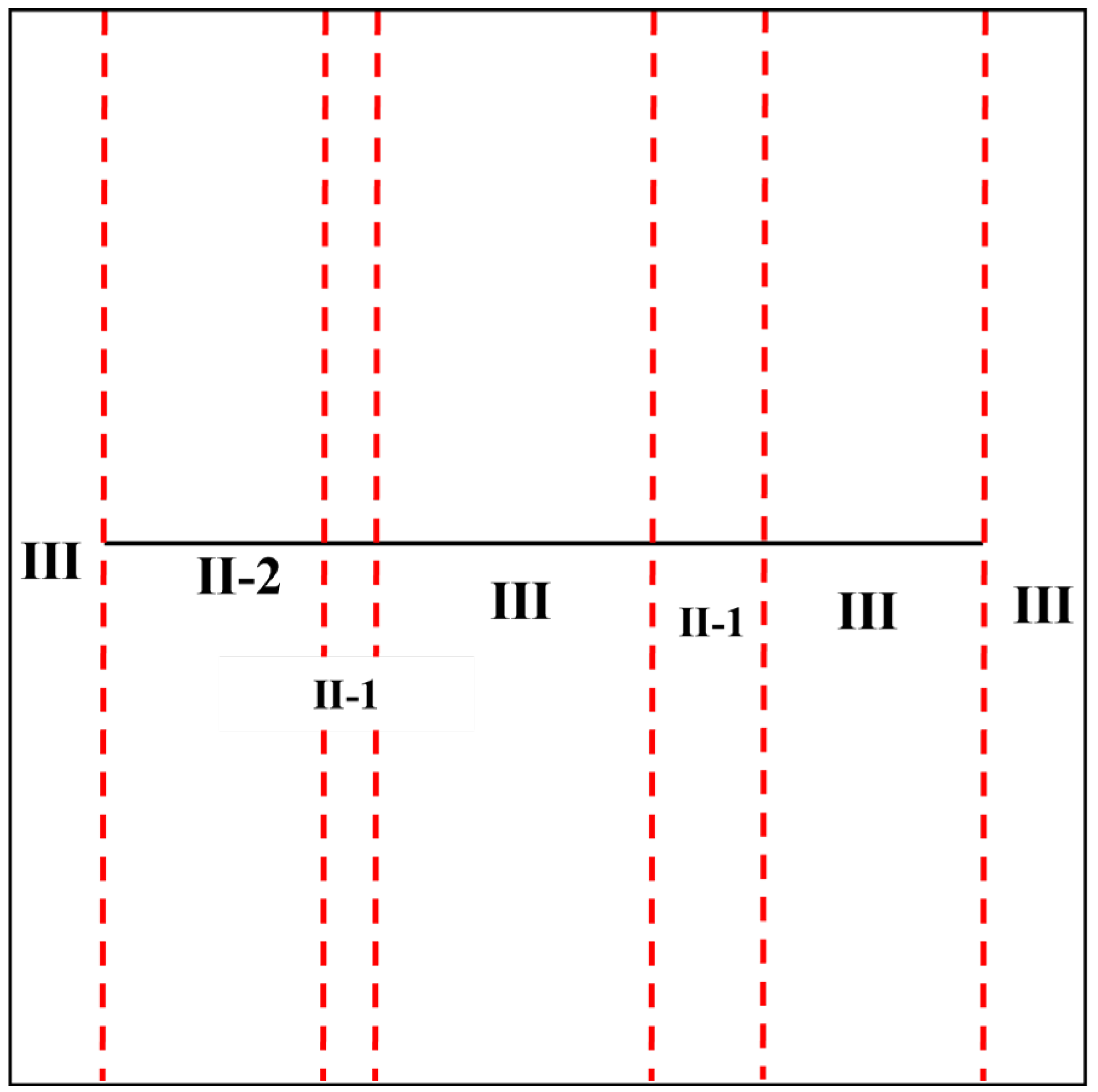
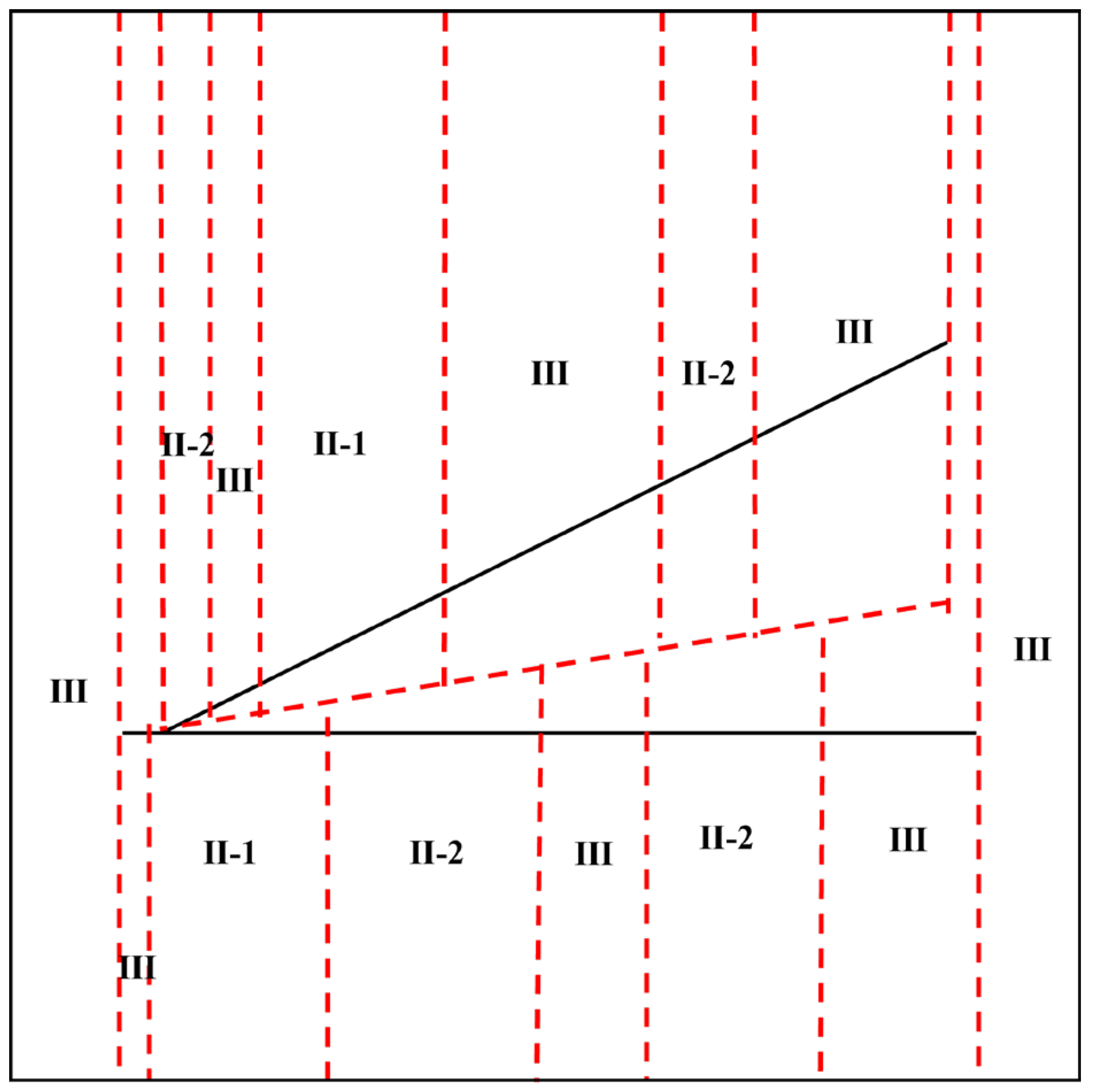
3. Experimental Parameters and Program Design

3.1. Experimental Parameters

Based on the data of a gas field, we can find the length of horizontal wells and planar multi-branch wells; the production differential pressure; fluid viscosity; permeability and other gas reservoir parameters and wellbore parameters, determine the main parameters, such as the length of copper wire and the experimental voltage of the hydroelectric simulation experimental model of horizontal wells and planar multi-branch wells; and, at the same time, we can calculate the similarity coefficients based on the similarity relation equation. The specific parameters are shown in Table 1 and Table 2.

3.2. Experimental Program

First of all, the preparation of the experiment is carried out, and the physical parameters of horizontal wells and planar multi-branch wells are processed to obtain the average permeability of each section required for the experiment, so as to determine the CuSO4 solution used for the experiment and the conductivity of each section of the gel, and to configure the experimental materials; furthermore, the simulated wellbore and the experimental materials are placed in the designated position of the electrolysis tank to turn on the circuit and prepare for the experiment; then, we measure the voltage at each point near the model to draw an isobar graph to analyze the seepage characteristics of the near wellbore area; finally, measure the current in the circuit, convert it to yield, and then plot the relationship between daily gas production and the difference of the pressure function to analyze the production capacity characteristics. The specific experimental program is as follows:
(1) Experiment preparation. The hydroelectric simulation experiments in homogeneous and non-homogeneous reservoir conditions were carried out successively using pre-made simulated horizontal wells and simulated planar multi-branch wells, with the length of the main branch of both horizontal wells and planar multi-branch wells being 40 cm, and the length of the branch being 42 cm.
By weighted averaging of the along-track permeability distribution of the horizontal wells, it was converted to a permeability of 2.24 mD under homogeneous conditions, which was taken as the permeability of the formation under homogeneous reservoir conditions, and, based on this, the CuSO4 solution corresponding to the electrical conductivity was configured.
The physical parameters along the horizontal section of the simulated wellbore were converted according to the physical parameters along the horizontal well; the permeability of each section of the sweet spot was weighted and averaged to obtain the average permeability of each section; the electrical conductivity of the gel corresponding to each section was determined based on the converted permeability; and the CuSO4 gel was fabricated in accordance with the electrical conductivity and lined up in the electrolysis tank for the gel and the simulated horizontal wellbore (see Figure 2).
Using the weighted average of the permeability distribution along the main branch and the branches of the planar multi-branch wells, the permeability of the planar multi-branch wells under homogeneous conditions was discounted to 1.33 mD, which was taken as the permeability of the formation under homogeneous reservoir conditions. Based on this, the corresponding conductivity CuSO4 solution was configured.
The physical parameters along the main branch and the branch horizontal section of the simulated wellbore were converted according to the physical parameters along the plane multi-branch well, and the sweet spot’s permeability of each section of the main branch and the branch was weighted to obtain the average permeability of each section, and the conductivity of the gel corresponding to each section was determined based on the converted permeability. Furthermore, the CuSO4 gel was made according to the conductivity, while the gel and the simulated planar multi-branch main branch and the branch of the wellbore were lined up in an electrolyzer (see Figure 3).
(2) Measurement of voltage at each point. The model was placed in the center of the electrolysis tank, and the distribution of equipotential lines was measured by using a multimeter probe, so as to draw the pressure distribution map. Then, the images under the two experimental conditions were compared, so as to study the influence of reservoir inhomogeneity on the seepage characteristics of the formations in horizontal wells and planar multi-branched wells, as well as the differences between the seepage characteristics of the horizontal wells and the planar multi-branched wells.
(3) Measurement of loop current. The experiments were conducted on horizontal wells and planar multi-branch wells under homogeneous and non-homogeneous reservoir conditions successively, and the circuit current size under different voltages was measured by changing the voltage. After converting the experimental current to the actual production, the production under the two experimental conditions was compared to study the effect of reservoir inhomogeneity on production.

4. Analysis of Results

4.1. Comparison of Seepage and Capacity Characteristics of Different Well Types in Homogeneous Reservoirs

The data recorded in each group of experiments were used to draw the pressure distribution map and the relationship between daily gas production and the pressure function difference in the near wellbore area of horizontal wells and planar multi-branch wells under the condition of homogeneous reservoir, so as to reflect the seepage characteristics and production capacity characteristics of horizontal wells and planar multi-branch wells.

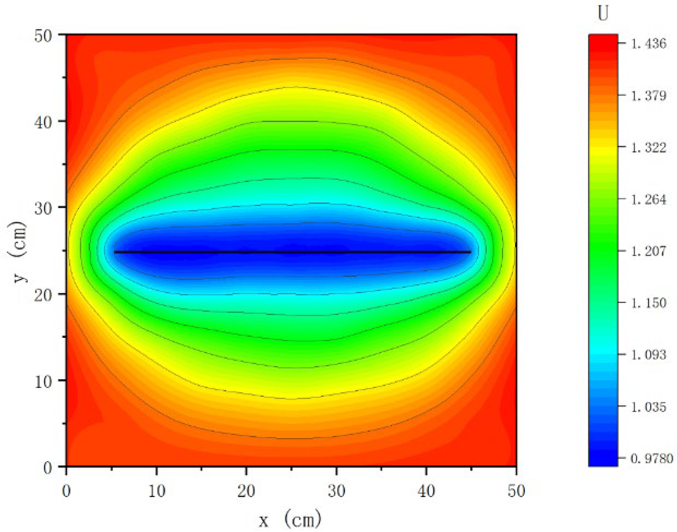
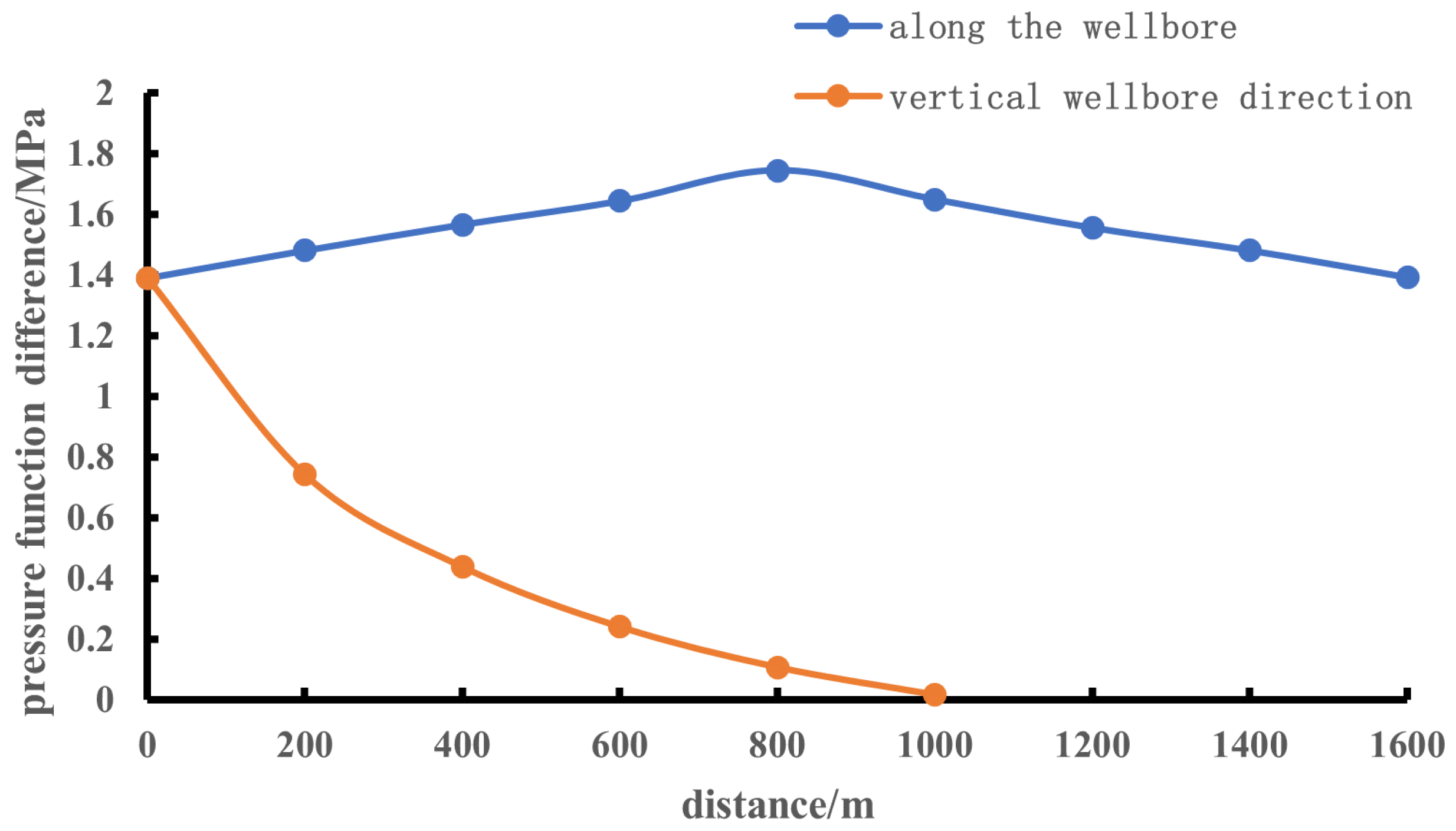
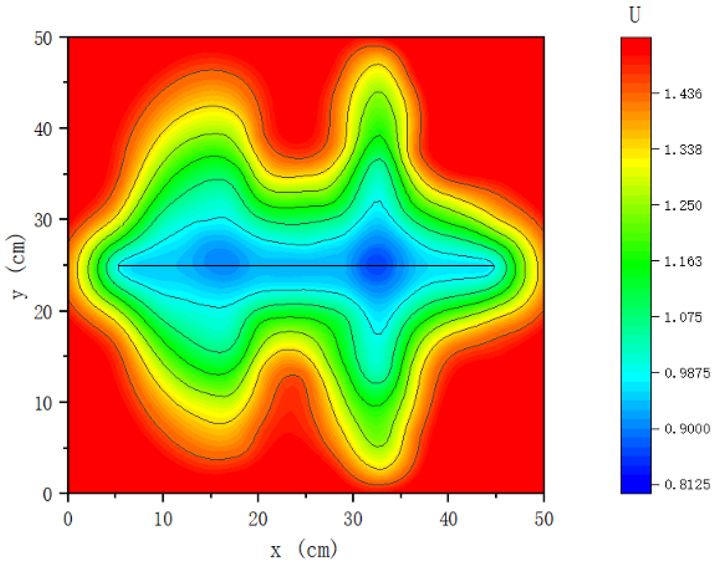
4.1.1. Seepage Characterization

As can be seen in Figure 4, the pressure in the near wellbore area of horizontal wells under homogeneous reservoir conditions shows an elliptical distribution, and the pressure distribution in the far wellbore area is approximately circular; at the two ends of the horizontal section, the isobars are dense, while along the middle of the horizontal wellbore the isobars are sparse; the seepage field is mainly distributed in the vicinity of the horizontal section, and the fluids are uniformly converging along the wellbore, while away from the wellbore the isobars are sparse, and the pressure is slowly decreasing.
As can be seen in Figure 5, the pressure in the near wellbore area of the main branch and the branch of the planar multi-branch well is lower, and the pressure in the far wellbore area is higher; the pressure in the near wellbore area is not elliptically distributed, and the far wellbore area does not show a circular distribution, but an elliptical distribution; the isobars at the end of the branch are dense and concave between the main branch and the branch, and the area covered in the direction of the extension of the branch is larger; the range of the pressure perturbation is significantly increased, and because of the branch interference, the intersection of the main branch and the branch forms a low-pressure area; furthermore, the pressure distribution is significantly affected by the morphology of the branch wells.
Comparing Figure 4 and Figure 5, the horizontal wells show typical elliptical–circular pressure distributions in homogeneous reservoirs, reflecting their composite characteristics of radial and linear flow; planar multi-branch wells form asymmetric pressure fields, due to branching disturbances, and the elliptical long axes of the far-well zones are extended along the extension direction of the main branches, with the ends of the branches increasing the range of the pressure disturbances. Local low-pressure zones are formed at the branch intersections, indicating that the multi-branch structure further enhances the degree of reservoir utilization through branch interference. Meanwhile, compared to horizontal wells, planar multi-branch wells significantly expand the control range due to branch extension, which verifies the mechanism of multi-branch wells to enhance the reservoir utilization efficiency by increasing the seepage area.
In order to quantitatively analyze the seepage characteristics, the relationship between the distance along the wellbore direction, the distance in the perpendicular wellbore direction, and the pressure function difference in the near wellbore area was made with the left heel end of the horizontal wellbore as the origin, as shown in Figure 6; the relationship between the distance along the wellbore direction and the pressure function difference in the near wellbore area was made with the left heel end of the main branch and branch wellbore as the origin, as shown in Figure 7.
As can be seen in Figure 6, along the horizontal wellbore direction, the pressure function difference is symmetrically distributed, high in the middle of the wellbore and low at both ends. The pressure function difference in the vertical wellbore direction shows a decreasing trend, with a pressure function difference of about 0.741 MPa at 200 m from the wellbore, and decreasing to 0.107 MPa at 800 m; furthermore, the pressure function difference tends to flatten in the area far away from the wellbore, reflecting that seepage in horizontal wells in homogeneous reservoirs is dominated by radial flow.
As can be seen in Figure 7, planar multi-branch wells have the highest pressure function difference between the main branch and the middle part of the branch, indicating that the local low-pressure zone is formed in this region due to branching disturbance, which reduces the seepage resistance, improves the efficiency of fluid replacement, and enhances the degree of utilization of the reservoir. Compared to horizontal wells, planar multi-branch wells have a wider range of pressure disturbance due to longer seepage paths.
Comparing Figure 6 and Figure 7, the pressure distribution of horizontal wells is symmetrically distributed, with the wellbore as the center, reflecting the typical elliptical–circular seepage characteristics, whereas the pressure distribution of planar multi-branch wells is asymmetric and multi-segmented due to the presence of branches. The low-pressure zone at the intersection of the main branch and the branch significantly enhances the local seepage efficiency; furthermore, the pressure fluctuation in the inter-branch area is more intense, indicating that the branching structure enhances the overall fluid mobilization by extending the seepage path and expanding the seepage area. This result is consistent with the conclusion of the pressure distribution diagram, which further verifies the mechanism of optimizing the seepage field distribution of multi-branch wells through branch interference.

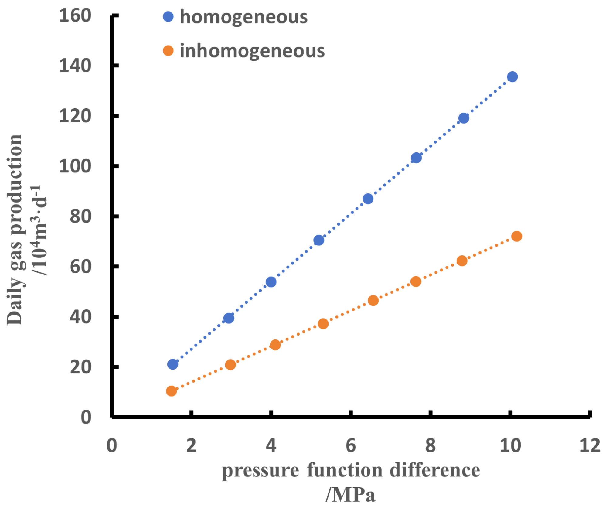
4.1.2. Characterization of Production Capacity

As can be seen in Figure 8, under the production pressure difference (4 MPa), the horizontal wells under the homogeneous reservoir conditions have a gas recovery index of 24.6 × 10⁴ m3/d·MPa−1 by discounting, which translates to a daily gas production of about 98.4 × 10⁴ m3/d.
Figure 9 shows that under the production pressure difference (10 MPa), the gas recovery index of planar multi-branch wells under homogeneous reservoir conditions is 13.5 × 10⁴ m3/d·MPa−1 by conversion, and the daily gas production is about 135 × 104 m3/d. Compared to horizontal wells, planar multi-branch wells in homogeneous reservoirs expand the seepage area by multi-branch structure, which significantly improves the efficiency of seepage, and thus increases the degree of reservoir utilization, leading to higher production.

4.2. Comparison of Seepage and Capacity Characteristics of Different Well Types in Non-Homogeneous Reservoirs

Through the data recorded in each group of experiments, the pressure distributions of horizontal wells and planar multi-branch wells in the near wellbore area under non-homogeneous reservoir conditions, and the relationship between daily gas production and the difference in the pressure function, are plotted and compared to the experimental results under homogeneous reservoir conditions, so as to reflect the seepage characterization and production capacity characterization of the horizontal wells and planar multi-branch wells under the influence of non-homogeneity of the reservoir in the actual stratigraphic formation.

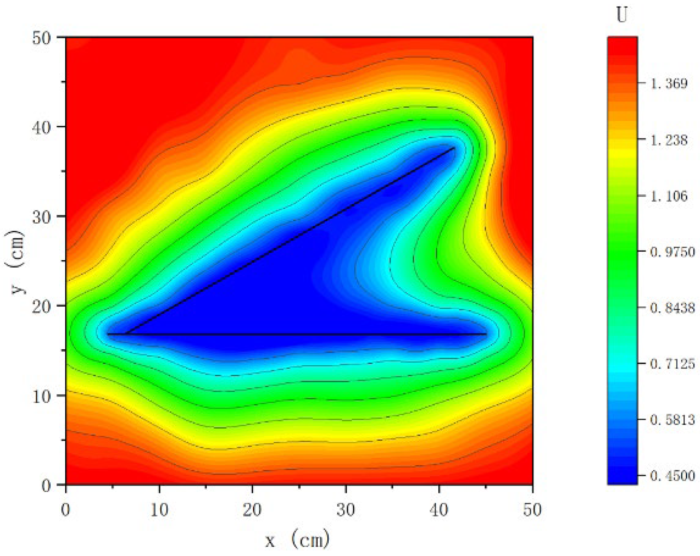
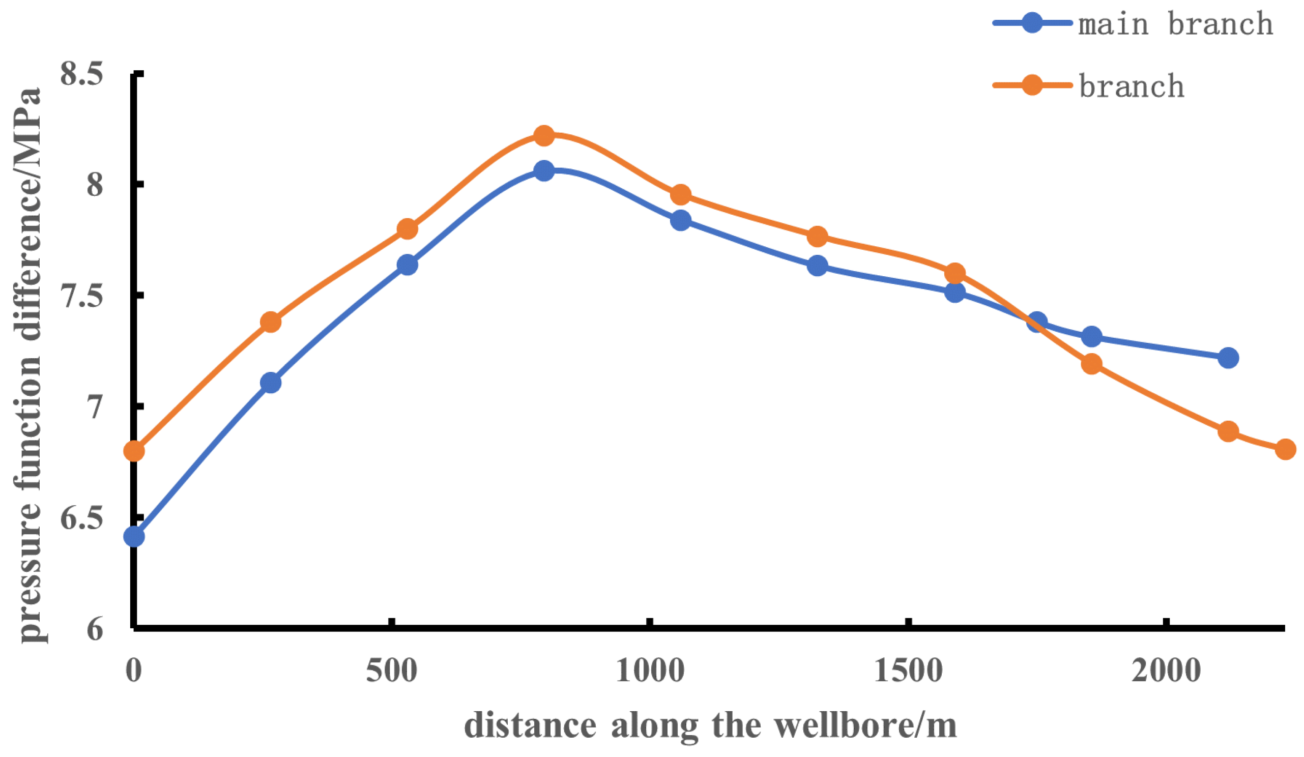
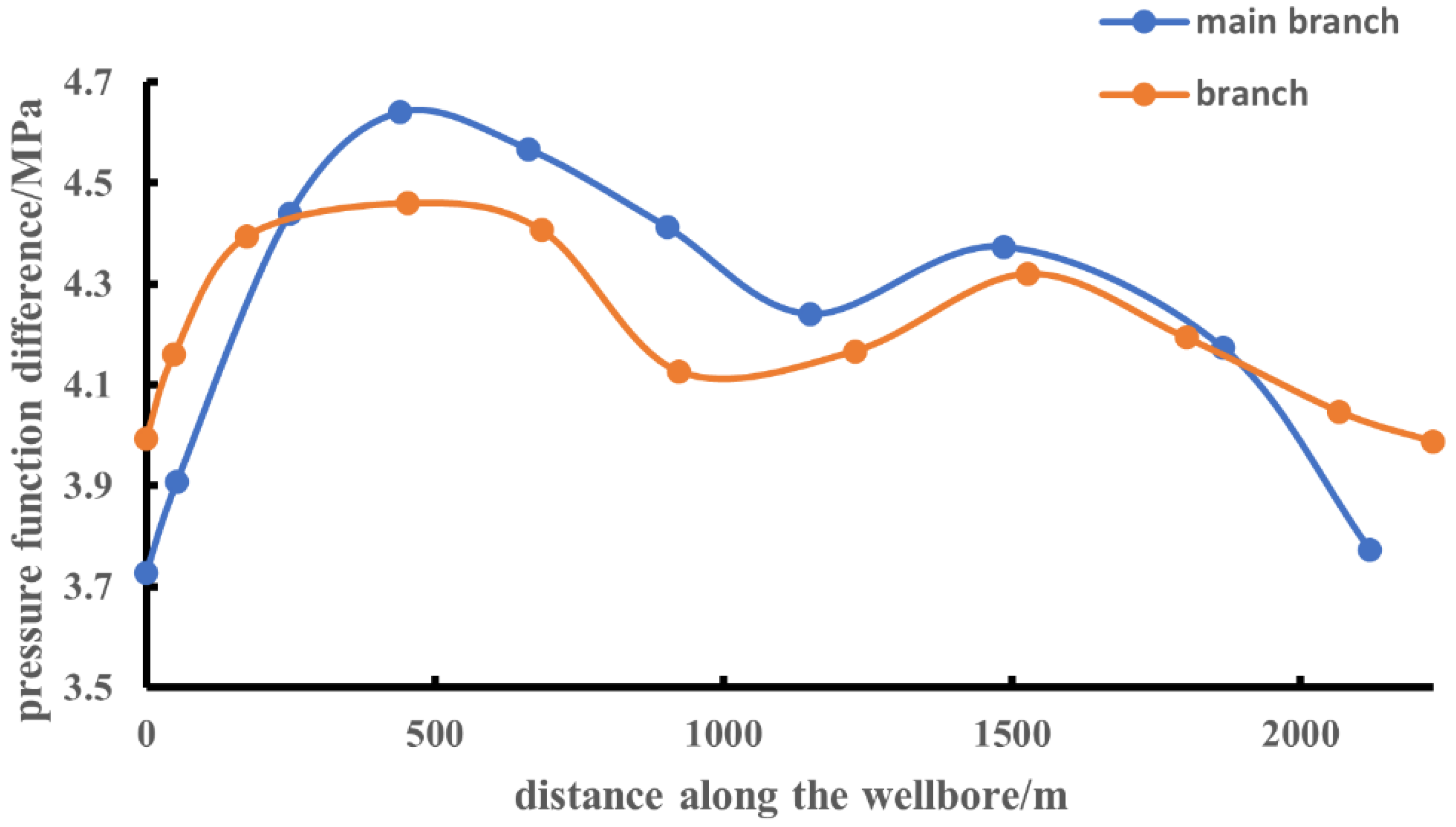
4.2.1. Seepage Characterization

As can be seen in Figure 10, compared to the homogeneous reservoir conditions, the pressure distribution of the non-homogeneous reservoir fluctuates under the influence of the physical distribution, and there is no elliptical distribution in the near wellbore area, nor circular distribution in the far wellbore area, but it is controlled by the physical distribution. The pressure is lower in the high-permeability region than in the low-permeability region, while the mobilization in the high-permeability region is larger than that in the low-permeability region, and the fluid mainly converges to the horizontal well along the high-permeability region. Furthermore, the fluid in the low-permeability area is difficult to be effectively utilized, resulting in the reduction of the actual control range of the horizontal well.
As can be seen in Figure 11, compared to the homogeneous reservoir conditions, the pressure distribution of planar multi-branch wells fluctuates under the double influence of branch interference and physical distribution, and the lowest value of the pressure occurs at the connection of the high-permeability region near the intersection of the main branch and the branch. The low-permeability region between the main branch and the branch is also well-utilized under the influence of branch interference.
Comparing Figure 10 and Figure 11, under non-homogeneous conditions, the pressure distribution of horizontal wells is controlled by permeability strips, forming local low-pressure zones in the high-permeability zones, with isobars shifted to the high-permeability zones. Furthermore, isobars in the low-permeability zones are sparse, whereas, in planar multi-branched wells, the pressure of the high-permeability zones in the main branch intersected with the branch is further reduced, and, at the same time, the low-permeability areas are compensated for by the branching disturbances, so that the pressure of the low-permeability zones in the intersected areas of the main branches and the branches is significantly reduced. At the same time, the pressure in the low-permeability zone is significantly reduced by branching interference, which improves the utilization efficiency of the low-permeability zone, especially the utilization degree of the low-permeability zone between the branches. Compared to the horizontal wells, the planar multi-branching wells have increased the radius of the pressure disturbance, which indicates that the branching structure can break through the restriction of the high-permeability channel and enhance the utilization ability of the non-homogeneous reservoir.
In order to quantitatively analyze the seepage characteristics, the relationship between the distance along the wellbore direction and the distance in the perpendicular wellbore direction and the pressure function difference in the near wellbore area was made with the left heel end of the horizontal wellbore as the origin, as shown in Figure 12. The relationships between the distance along the wellbore direction and the pressure function difference in the near wellbore area were made with the left heel end of the main branch, with the branch wellbore as the origin, as shown in Figure 13.
As can be seen in Figure 12, along the horizontal wellbore, the pressure function difference rises significantly in the high-permeability section (e.g., x = 400~510 m and x = 1000~1190 m), reflecting that the difference in permeability leads to lower seepage resistance in the high-permeability zone, and the fluids preferentially converge along the high-permeability zone to form a localized low-pressure zone, while the pressure function difference varies gently in the low-permeability section (e.g., x = 510~1000 m and x = 1190~1600 m), indicating that it is difficult to move fluids effectively in the low-permeability zone.
As can be seen in Figure 13, the pressure function difference is the highest near x = 439.9 m in the high-permeability section of the main branch, which is affected by both branching interference and reservoir inhomogeneity, forming a low-pressure area; the low-permeability area in front of the branch (near x = 172.78 m) forms a strong drive channel due to the branching superposition effect, and the pressure function difference is significantly increased, indicating that branching interference forces fluid flow in the low-permeability area, which improves the mobilization efficiency of the low-permeability area.
Comparing Figure 12 and Figure 13, the pressure distribution of horizontal wells is significantly controlled by permeability strips, and the pressure function difference is concentrated in the local high-permeability zones, resulting in the fluid flow path being concentrated in the high-permeability zones, whereas planar multi-branching wells, through branching interference, make the pressure of the high-permeability zones at the intersection of the main branch and the branch decrease further. Thus, the pressure function difference of the low-permeability zones increases, forcing fluid flow in the low-permeability zones, which verifies that the branching interference is able to enhance the mobilization degree of the low-permeability zone.

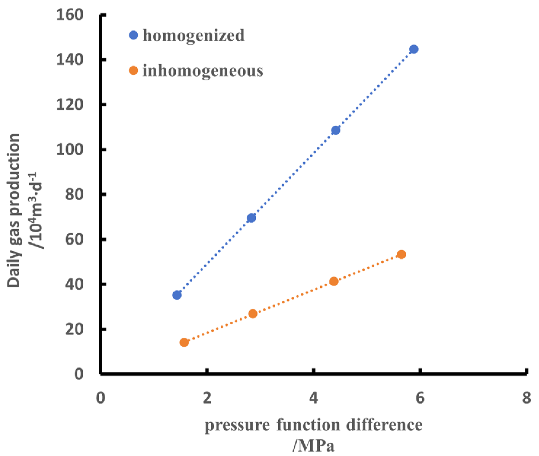
4.2.2. Characterization of Production Capacity

As can be seen in Figure 14, under the production pressure difference (4 MPa), the horizontal wells under non-homogeneous reservoir conditions have a gas recovery index of 9.4 × 10⁴ m3/d·MPa−1 by discounting, which translates to a daily gas production of about 37.6 × 10⁴ m3/d, which is close to the actual daily gas production. Meanwhile, under the same pressure function difference, the daily gas production is smaller than that of the homogeneous reservoir conditions, and the production gap increases with the pressure function difference of increases.
It can be seen in Figure 15 that under the production pressure difference (10 MPa), the gas recovery index of planar multi-branch wells under non-homogeneous reservoir conditions is 7.09 × 10⁴ m3/d·MPa−1 by conversion, and the converted daily gas production is about 70.9 × 10⁴ m3/d, which is lower than that of the homogeneous reservoir conditions, which shows that when the non-homogeneous reservoir condition is converted to a homogeneous reservoir condition, it weakens the influence of the low-permeability region on the daily gas production of the gas wells and the interference of the high-permeability region on the low-permeability region, which results in the higher production under the homogeneous reservoir condition.

5. Discussion

In this study, we used copper sulfate gel with adjustable electrical conductivity to simulate the permeability distribution through hydroelectric simulation experiments, solved the limitations of traditional hydroelectric simulation methods in simulating non-homogeneous reservoirs, and systematically compared the seepage characteristics and production capacity differences between horizontal wells and planar multi-branched wells under homogeneous and non-homogeneous conditions, revealing the effects of non-homogeneity on seepage characteristics and production capacity, and confirming the advantages of multi-branched structures in expanding the seepage area and enhancing pressure perturbation. It confirms the advantage of the multi-branch structure in expanding the seepage area and enhancing the pressure perturbation.
Meanwhile, this study has some limitations. Only single-phase gas seepage is simulated, and the effect of gas–water two-phase flow on seepage is not involved. The complex conditions of non-homogeneous and multiphase flow need to be further investigated.

6. Conclusions

In this study, by constructing a copper sulfate gel-based experimental model for the hydroelectric simulation of complex structural wells in non-homogeneous gas reservoirs, we systematically analyzed the effects of reservoir inhomogeneity on the seepage characteristics and production capacity of horizontal wells and planar multi-branch wells, and drew the following conclusions:
(1) In homogeneous reservoirs, the pressure in horizontal wells is elliptical–circular, and the pressure in planar multi-branch wells is controlled by the branching pattern, which is elliptical in the far wellbore area; the non-homogeneity leads to fluctuations in pressure distribution, with the pressure in high-permeability areas being lower, and the fluids converging preferentially, while the utilization of low-permeability areas is limited. The branching interference of planar multi-branch wells and the superimposed effect of reservoir non-homogeneity make the pressure lowest at the intersection of the main branch and the branch, and the low-permeability area between the branches can be partially utilized due to the influence of branching interference.
(2) Under non-homogeneous conditions, the daily gas production of horizontal wells and planar multi-branch wells are 37.6 × 10⁴ m3/d and 70.9 × 10⁴ m3/d, respectively, and the gap between the production and that of homogeneous conditions increases as the difference in the pressure function increases, which indicates that when the non-homogeneous reservoir conditions are converted to homogeneous reservoir conditions, the influence of the low-permeability area on the daily gas production of the gas wells, as well as the interference of the high-permeability region with the low-permeability region, are weakened.
(3) Compared to horizontal wells, planar multi-branch wells expand the seepage area through the branching structure, which enhances the ability to utilize the non-homogeneous reservoir and effectively improves the production.
(4) A hydroelectric simulation method for non-homogeneous reservoirs based on copper sulfate gel is proposed. Copper sulfate gel can accurately simulate the distribution of different permeability by adjusting the electrical conductivity, and the experimental model is in good agreement with the actual reservoir data, which provide an effective means for the study of the seepage mechanism in non-homogeneous gas reservoirs.
Based on the data of a gas field, this study provides an experimental basis and guidance for the development of non-homogeneous gas reservoirs by revealing the influence laws of reservoir non-homogeneity and well structure on seepage characteristics and production capacity.

Author Contributions

Conceptualization, H.L.; methodology, H.L., Q.J., Z.J. and B.Y.; writing—original draft preparation, Q.J. and B.Y.; writing—review and editing, Q.J.; project administration, Z.J. All authors have read and agreed to the published version of the manuscript.

Funding

The research of this paper is based on the major scientific and technological project of PetroChina (China) Co., Ltd., “Research and demonstration application of key technologies for efficient development of low permeability atmospheric fields in the East China Sea” (E-Y424RY03).

Data Availability Statement

Data are contained within the article.

Conflicts of Interest

The authors Hengjie Liao and Zhehao Jiang are employed by the China National Offshore Oil Corporation (China) Limited Shanghai Branch. The remaining authors declare that the research was conducted in the absence of any commercial or financial relationships that could be construed as potential conflicts of interest.

References

  1. Wu, X.D.; Sui, X.F.; An, Y.S.; Zhang, F.X.; Chen, Y.G. Electrolytic simulation experiment of fractured horizontal well. J. Pet. 2009, 30, 740–743. [Google Scholar]
  2. Mao, C.X. Electric Simulation Test and Seepage Study; Water Resources Press: Beijing, China, 1981. [Google Scholar]
  3. Gao, F.; Han, G.Q.; Wu, X.D.; Zhu, M.; Wang, Y.N.; Cen, X.Q.; Zhang, R. The Research of Experimental Method about Hydroelectric Simulation. Sci. Technol. Eng. 2012, 12, 3839–3843. [Google Scholar]
  4. Wang, T.Q.; Huang, Y. Electrical Simulation Experiment of the Seepage of Zone Near the Borehole in Symmetric Herringbone Wells. Contemp. Chem. Ind. 2017, 46, 54–56. [Google Scholar]
  5. Han, G.Q.; Li, X.F.; Wu, X.D. Experiment research of electric analogy for multi—Branch wells. Nat. Gas Ind. 2004, 24, 99–101. [Google Scholar]
  6. Huang, S.J.; Cheng, L.S.; Zhao, F.L.; Li, C.L. Experimental research of flow mechanism of near wellbore area of fishbone wells. Oil Drill. Process 2006, 28, 58–60. [Google Scholar]
  7. Qu, Z.Q.; Xu, X.; Liu, J.M.; Yang, X.Y. Electric analogy experiment of the productivity of radial-distributing multi-branch horizontal wells. J. Xi’an Pet. Univ. (Nat. Sci. Ed.) 2007, 22, 65. [Google Scholar]
  8. Liu, H.; Shi, C.P.; Pan, Y.; Leng, J.; Xu, Z.J. Electrolytic simulation experiment of fractured multilateral horizontal well. J. Liaoning Univ. Petrochem. Technol. 2015, 35, 43–46. [Google Scholar]
  9. Ozawa, M.; Suzuki, S. Microstructural development of natural hydroxyapatite originated from fish-bone waste through heat treatment. J. Am. Ceram. Soc. 2002, 85, 1315–1317. [Google Scholar] [CrossRef]
  10. Jiang, M.C. Study on Interbranch Pressure and Productivity Interference of Multi-branch Wells. Master’s Thesis, China University of Petroleum, Beijing, China, 2023. [Google Scholar] [CrossRef]
  11. Ji, G.F.; Liu, Z.Q.; Zhao, W.W.; Nan, C.Y. Similarity simulation of tight oil horizontal well post-fracturing productivity based on principle of hydropower similarity. J. Heilongjiang Univ. Sci. Technol. 2024, 34, 440–445. [Google Scholar]
  12. Yin, J.W. Experimental study on hydraulic fracturing simulation of horizontal well fracturing on well production. Energy Environ. Prot. 2017, 39, 167–170. [Google Scholar]
  13. Su, G.D.; Zhang, P.; Gu, X.; Han, B.Y.; Yi, P.; Li, M.Y. Design of Virtual Teaching Platform for Hydroelectric Simulation Experiment. Lab. Res. Explor. 2018, 37, 105–109. [Google Scholar]
  14. Ji, G.F.; Zhou, Y.; Wang, M.; Xu, C.Z. Electric simulation of seepage flow for tight-oil horizontal well staged fracturing and considering start-up pressure. Energy Environ. Prot. 2019, 41, 64–67. [Google Scholar]
  15. Sun, X.C.; Liu, Z.L.; Ji, G.F.; Liu, Z.T.; Xu, Z. Hydro-electric Simulation of the Influence of Fracture Parameters on Seepage in Horizontal Wells After Fracturing in Tight Oil Reservoirs. Contemp. Chem. Ind. 2020, 49, 2736–2741. [Google Scholar]
  16. Lu, T.D. Study on Flow Law of Complex Fracture Network in Tight Reservoir. Master’s Thesis, China University of Petroleum, Beijing, China, 2020. [Google Scholar]
  17. Liu, H.L. Similarity Experiment Study on Directional Pinnate Multi-branch Horizontal Wells of Coalbed Methane. Master’s Thesis, Liaoning University of Engineering and Technology, Fuxin, China, 2021. [Google Scholar]
  18. Zhai, L.; Yang, M.; Yan, C.; Tian, T.; Huang, S. Dynamic distribution characteristics of oil and water during water flooding in a fishbone well with different branch angles. ACS Omega 2022, 7, 27206–27215. [Google Scholar] [CrossRef] [PubMed]
  19. Liu, Z.Q. Study on the Productivity Evaluation of Refracturing in Tight Oil Horizontal Wells Based on Hydroelectric Simulation. Master’s Thesis, Yangtze University, Jingzhou, China, 2024. [Google Scholar] [CrossRef]
  20. Li, Y.C.; Liu, H.L.; Jia, J.Z. Hydroelectric simulation test of coalbed methane in symmetric multi branch horizontal wells. Coal Sci. Technol. 2022, 50, 135–142. [Google Scholar] [CrossRef]
  21. Kukharova, T.; Maltsev, P.; Novozhilov, I. Development of a Control System for Pressure Distribution During Gas Production in a Structurally Complex Field. Appl. Syst. Innov. 2025, 8, 51. [Google Scholar] [CrossRef]
Figure 1. Schematic diagram of the hydropower simulation experiment setup: (a) schematic diagram of the horizontal well experimental setup; (b) schematic diagram of the experimental setup for planar multi-branch wells.
Energies 18 02794 g001
Figure 2. Experimental scheme of horizontal wells under non-homogeneous reservoir conditions.
Energies 18 02794 g002
Figure 3. Experimental scheme of planar multi-branch wells under non-homogeneous reservoir conditions.
Energies 18 02794 g003
Figure 4. Pressure distribution of horizontal wells under homogeneous conditions.
Energies 18 02794 g004
Figure 5. Pressure distribution of planar multi-branch wells under homogeneous conditions.
Energies 18 02794 g005
Figure 6. Horizontal well pressure function difference versus distance.
Energies 18 02794 g006
Figure 7. Plane multi-branch well pressure function difference versus distance along the wellbore direction.
Energies 18 02794 g007
Figure 8. Relationship between daily gas production and the difference in pressure functions for horizontal wells under homogeneous conditions.
Energies 18 02794 g008
Figure 9. Relationship between daily gas production and the difference in pressure functions in planar multi-branch wells under homogeneous conditions.
Energies 18 02794 g009
Figure 10. Pressure distribution of horizontal wells under non-homogeneous conditions.
Energies 18 02794 g010
Figure 11. Pressure distribution of planar multi-branch wells under non-homogeneous conditions.
Energies 18 02794 g011
Figure 12. Relation between pressure function difference and distance of horizontal well.
Energies 18 02794 g012
Figure 13. Relation between pressure function difference of planar multi-branch wells and distance along wellbore direction.
Energies 18 02794 g013
Figure 14. Relationship between daily gas production and the difference in pressure functions in horizontal wells under nonhomogeneous conditions.
Energies 18 02794 g014
Figure 15. Relationship between daily gas production and the difference in pressure functions in planar multi-branch wells under nonhomogeneous conditions.
Energies 18 02794 g015
Table 1. Horizontal well stratigraphic model and experimental model parameters comparison table.
Stratigraphic Model ParametersNumerical ValueExperimental Model ParametersNumerical Value
Horizontal well length/m1600Copper wire length/m0.4
Production differential pressure/MPa4Experimental voltage/V1.5
Viscosity/mPa·s2.4 × 10−2Geometric similarity coefficient CL2.5 × 10−4
Pressure similarity coefficient Cp/V·(MPa)−10.375Resistance similarity coefficient Cr/μm2·[(mPa·s)·(μs/cm)]−193.22
Flow similarity coefficient Cq/mA·(m3/d)−14 × 10−3Mobility similarity coefficient Cρ/(μs/cm)·[mPa·s·(10−3 μm2)−1]42.91
Table 2. Comparison of stratigraphic model and experimental model parameters for planar multi-branch wells.
Stratigraphic Model ParametersNumerical ValueExperimental Model ParametersNumerical Value
Length of horizontal section of main branch/m2120Length of main branch copper wire/m0.4
Length of branch horizontal section/m2230Branch copper wire length/m0.42
Production differential pressure/MPa10Experimental voltage/V1.5
Viscosity/mPa·s2.4 × 10−2Geometric similarity coefficient CL1.89 × 10−4
Pressure similarity coefficient Cp/V·(MPa)−10.15Resistance similarity coefficient Cr/μm2·[(mPa·s)·(μs/cm)]−173.49
Flow similarity coefficient Cq/mA·(m3/d)−12 × 10−3Mobility similarity coefficient Cρ/(μs/cm)·[mPa·s·(10−3 μm2)−1]72
Disclaimer/Publisher’s Note: The statements, opinions and data contained in all publications are solely those of the individual author(s) and contributor(s) and not of MDPI and/or the editor(s). MDPI and/or the editor(s) disclaim responsibility for any injury to people or property resulting from any ideas, methods, instructions or products referred to in the content.

