1. Introduction
With the large-scale integration of distributed generation, energy storage systems, and various controllable loads [
1,
2,
3,
4], power distribution systems exhibit significant differences in dynamic response characteristics, regulation capabilities, and control interaction mechanisms [
5,
6,
7], thereby increasing the complexity of system operation. This high degree of heterogeneity substantially raises the difficulty of unified scheduling and global coordination, posing severe challenges to traditional centralized control approaches in managing complex control tasks [
8,
9]. Meanwhile, the growing demand for flexible control continues to push the system toward higher requirements in regulation frequency, response latency, and edge-side execution capability [
10,
11,
12]. In particular, as emerging applications such as electric vehicle clusters [
13] and virtual power plant aggregation [
14] are rapidly deployed, distribution network control tasks are becoming increasingly decentralized and dynamic, further intensifying the communication and computational burdens of centralized control architectures.
To address the above challenges, edge agents have been introduced as novel solutions for distributed control in power distribution networks [
15,
16,
17]. By offloading computationally lightweight tasks from the central controller to devices closer to the field, the system enables localized real-time data perception and coordinated regulation with the control center, thereby improving response speed and operational flexibility [
18]. Researchers have explored the engineering pathway of deploying edge agents in power systems. Reference [
19] systematically elaborates on the integrated architecture of edge agents and artificial intelligence technologies in the context of the power Internet of Things. Reference [
20] constructs a single-phase ground fault section location model by integrating deep learning algorithms into the edge agent framework. References [
21,
22] propose optimized deployment strategies for edge agent clusters in distribution networks from the perspectives of software-defined network architecture and fault handling requirements, respectively. Existing studies mainly focus on how edge agents overcome the computational bottlenecks of centralized control [
23,
24]. However, achieving optimal control performance under resource-constrained conditions remains a key challenge between academic research and practical deployment. Current approaches to address this issue include lightweight deployment [
25] and rational allocation of computing resources [
26,
27,
28].
Lightweight deployment encompasses both algorithm-level and model-level strategies. Current algorithm deployment often relies on pre-debugged embedding [
29], which is not suitable for large-scale, dynamic deployment and online updating across massive terminal devices. At the model level, existing continuous system operation models for edge agents typically rely on gradient-based iterative mechanisms, which lead to continuous occupation of communication bandwidth. In recent years, the hybrid characteristics of power systems have been recognized [
30], giving rise to hybrid system modeling approaches that abstract high-dimensional nonlinear systems as discrete event-triggered state transition systems. These methods achieve model order reduction by decoupling dynamic systems from discrete events [
31]. Moreover, modeling based on discrete event-driven mechanisms initiates state evolution computation only when events are triggered, significantly reducing the computational resource consumption of edge agents. Related technologies have already been validated in microgrid energy management systems [
32,
33].
In addition, in multi-objective optimization control of distribution networks [
34,
35], time-iterative continuous control often results in high redundancy of control commands, which severely limits the real-time responsiveness of control actions and increases the computational burden on edge agents. Current research primarily focuses on resource allocation algorithms to improve resource utilization efficiency [
36,
37]. However, systematic solutions for optimizing continuous control mechanisms under time-step constraints remain lacking. By adopting event-driven control, the system’s dynamic evolution can be transformed into a state transition trigger mechanism, thereby avoiding repetitive time-step iterations and improving computational resource efficiency [
38].
Based on the above background and challenges, this paper conducts research on distributed edge agent technology for distribution networks. First, an edge agent control architecture is designed in response to the diverse requirements of distributed control in distribution networks, enabling flexible deployment of control strategies through modules such as control configuration and intelligent computation. Second, a hybrid system model for distribution networks is established based on hybrid control theory, and an event-driven control configuration technique is proposed to discretize complex continuous control processes. The control strategy is formally modeled using AOE, where a joint dynamic mechanism of node events and edge actions is employed to achieve on-demand control. Furthermore, an automatic differentiation-based solver and a lightweight web application framework tailored for edge environments are developed to address the challenge of real-time optimization in resource-constrained settings. Finally, using station-level optimal dispatch as an application scenario, the proposed control configuration technique is applied to model and configure a distributed optimization strategy based on consensus algorithms, and the applicability of the proposed architecture and control method is validated through semi-physical simulation.
2. Edge Agent Architecture for Distributed Control
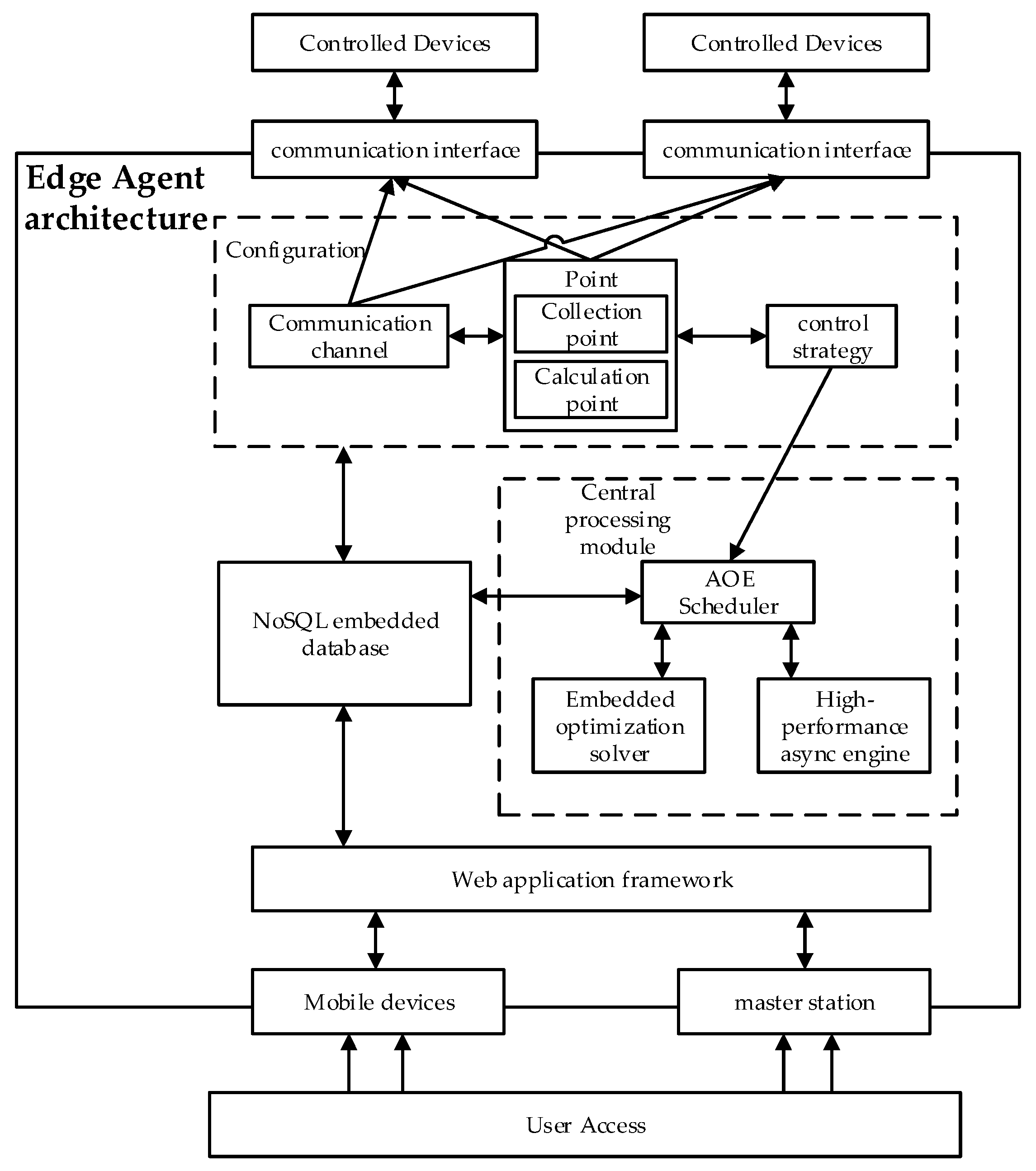
Edge agents are typically located close to distributed and flexible resources such as photovoltaics and energy storage systems, enabling localized computation and fast control near the source side by leveraging their edge computing capabilities. Through low-latency communication mechanisms, edge agents can not only execute localized control strategies but also respond to centralized optimization and dispatch, serving as a key enabler of local autonomy and global coordination in modern distribution networks. Based on this, the edge agent architecture constructed in this paper is shown in
Figure 1. The main functional modules are described as follows.
- 1.
Configuration Module
The edge agent provides a secondary development interface to users in the form of configuration, including control strategies, communication channels, and measurement points. The control strategy adopts a control configuration technique based on hybrid control theory, enabling custom editing of edge computing strategies. Channels are used to establish communication between the edge agent and controlled devices, supporting configuration of various communication protocols. Measurement points describe the state of the controlled objects and serve as the data foundation for control strategies or communication. They are categorized into acquisition points and calculation points.
- 2.
Central Processing Module
The AOE scheduler verifies, parses, and executes the configuration to enable optimized operation for the designed control scenario. The edge agent performs mathematical computations such as solving optimization models and equation systems within the control strategy using an automatic differentiation-based optimization solver. This paper uses the IPOPT optimization solver, which was developed by the Computational Infrastructure for Operations Research (COIN-OR) Foundation, located in Chicago, IL, USA. A coroutine-based high-performance asynchronous execution engine supports high-concurrency task scheduling, and an embedded database is integrated to handle data storage and management under resource-constrained conditions. The asynchronous execution engine in this paper is designed based on the Tokio asynchronous runtime framework, which is developed by contributors to the Tokio project and maintained by an organization based in the USA. The database is built on RocksDB, which was developed by Facebook Inc., headquartered in Menlo Park, CA, USA.
- 3.
Web Application Interface Module
The edge agent employs a browser-based web application as the user interface, providing an interactive platform for user operations and offering intuitive visualization of various data, reports, and the execution statuses of control strategies. The web application interface in this paper is designed using WebAssembly, which is led by the World Wide Web Consortium (W3C) and jointly promoted by major technology companies including Mozilla, Google, Microsoft, and Apple. The standardization and development efforts are primarily carried out in the USA.
3. Edge Agent Control Configuration Technology Based on Hybrid Control
3.1. Hybrid Control Theory
As a hybrid dynamic system, the distribution network requires coordinated operation between continuous variable control and discrete logical constraints to achieve multi-objective optimization [
32]. Its dynamic behavior is typically represented mathematically by high-dimensional nonlinear differential–algebraic equations, expressed as
where
x ∈
,
y ∈
, and
u ∈
represent the system state vector, output vector, and control vector, respectively. Traditional methods struggle to obtain satisfactory solutions within a limited time frame [
39]. To address this high-dimensional constrained variational problem, edge agents adopt a hybrid control approach. The full state space of the system is partitioned based on whether the multi-objective optimal operating conditions are satisfied, resulting in a satisfactory state set and an unsatisfactory state set, defined as
where
Xs(
T) represents the satisfactory state set of the system at time
T, that is, the state set where multi-objective optimal conditions are met;
represents the unsatisfactory state set at time
T; and
X(
T) represents the full state space of the system at time
T.
When the unsatisfactory state set
is an empty set, the system is considered to have achieved the desired operational objectives. At any time
T, when the system operating state enters
, an event
E is said to be triggered:
where
E represents the set of events,
D represents the system operating data, and
fE represents the logical evaluation function that determines whether an event in
E is generated based on
D.
When an event
E triggers the corresponding control strategy that drives the system operating state back to
Xs(
T), the system’s multi-objective optimal operation is achieved to a certain extent:
where
C represents the set of action commands executed by the edge agent, and
fC represents the transition function that generates control strategies from the event set
E.
The edge agent issues control commands to operate devices within the system, leading to a change in the system state that brings it back to the satisfactory state space. At this point, the system is in a no-event operational state, expressed as
where
x represents the state variable of the system, and
fx is the state equation that describes how the system state is changed through control. Equation (6) indicates that, through control actions, the event set
E becomes an empty set.
When Equation (6) holds, it indicates that the system is operating in a satisfactory state. In other words, satisfying Equation (6) also signifies that the system has achieved multi-objective optimal operation. In summary, the system is continuously in the process of event detection, handling, and elimination. The control method based on this theory is referred to as event-driven control.
3.2. Control Configuration Technology
3.2.1. Control Configuration
As shown in
Section 3.1, the hybrid control approach can be modeled using two key elements—events and action commands—and their interactions. Based on this, a control configuration technology is proposed in this paper. Control configuration is similar to “building blocks”, where control strategies are developed by selecting basic components, setting parameters, and combining them through a “configuration” process rather than traditional programming [
40]. Compared with conventional programming-based development, this approach offers advantages such as lower development barriers, inherent correctness, and greater generality.
3.2.2. Control Process Model Based on AOE
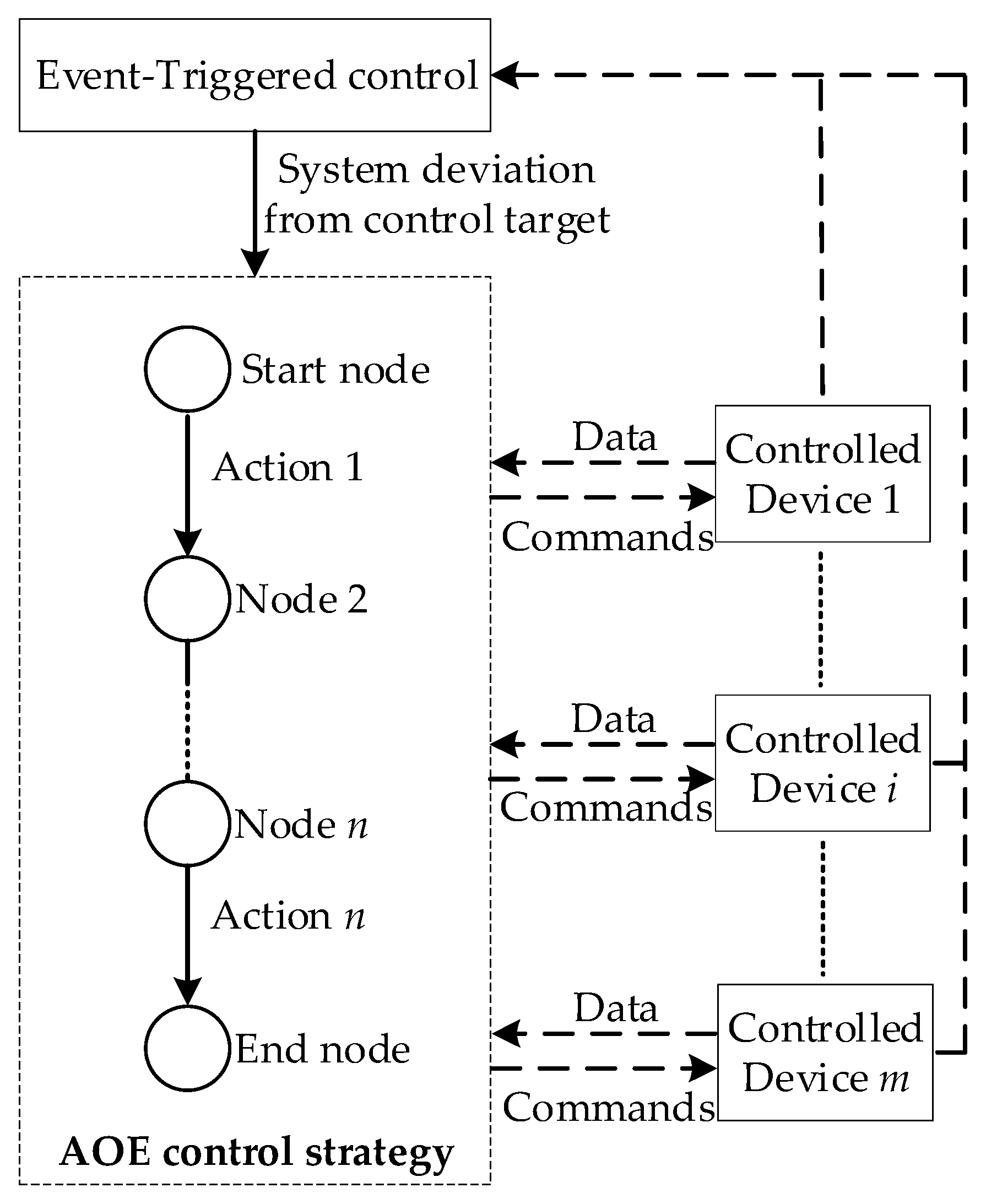
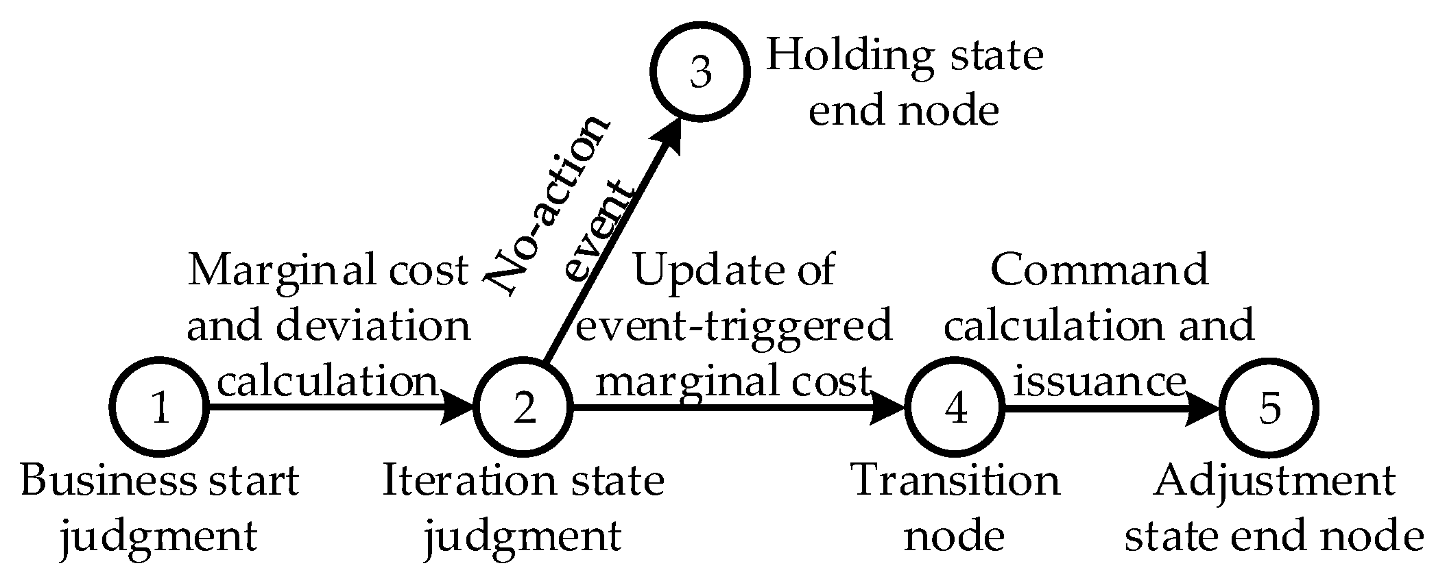
In distributed scenarios, the design and execution of control strategies are essential to ensuring efficient system operation. The control process can essentially be abstracted as an orderly transition of system states across multiple state sets. During the transition from an initial satisfactory state to the next, the system typically passes through several intermediate unsatisfactory states, which require corresponding control actions for correction. As this process cannot be handled by a single rule, a clear and structured modeling method for control logic is required. To this end, this paper adopts an AOE structure to intuitively describe the control process, with the corresponding control module workflow illustrated in
Figure 2. The AOE structure is fundamentally a directed acyclic graph with a single input and a single output, composed of nodes and directed edges. Its implementation details are presented as follows.
In terms of static modeling, the node set in the AOE structure corresponds to a subset of the event set E defined in Equation (3), with each node expression formulated according to the rules of fE. Each directed edge represents a control action, i.e., a subset of the instruction set C defined in Equation (4), and its action logic and execution expression are specified based on the rules of fC. The connectivity between nodes and edges reflects the logical dependencies and execution sequences between events and actions, and the resulting topological structure is consistent with the causal relationships among the elements in sets E and C. The terminal node serves as a validity check for the AOE-based control strategy, corresponding to Equations (5) and (6), to determine whether the current strategy can guide the system back to a satisfactory operational state, i.e., whether the intended control objective has been achieved.
In terms of dynamic execution, the control process starts from the initial node. The system continuously evaluates the event trigger expression defined at this node based on real-time measurement data. Once the expression is satisfied, the node is considered triggered, corresponding to the event generation described in
Section 3.1. The system then follows the conditional logic specified at the node to select the corresponding outgoing edge and executes the control action defined on that edge. The execution of the edge action is typically accompanied by updates to system state variables or the issuance of control commands, thereby driving the system toward the satisfactory state space. Upon completion of the action, the process transitions to the next node pointed to by the edge, where the evaluation cycle continues until the next triggering condition is met. Starting from the AOE initial node, this process continues to drive the system until the end node is reached, thus completing the entire execution of the control strategy. The migration at each step is determined by the triggering of node events, thereby implementing event-driven control strategy execution.
Taking the AOE-based control flow illustrated in
Figure 2 as an example, the edge agent first collects real-time operating data from nearby devices. Once the system is determined to have deviated from its target and entered an unsatisfactory state, the corresponding AOE control strategy is immediately activated to guide the system back to a satisfactory condition. The control process begins at the initial node, where the predefined logical expression is evaluated to determine whether the triggering condition is satisfied. If the condition holds true, the system proceeds along edge 1–2 to execute the corresponding control action and then transitions to the next node, node 2. This intermediate node typically represents a temporary state, which may be used to assess control effects or evaluate downstream branch logic. If the path condition is met, the system continues along edge 2–3 to execute the next control action and proceeds accordingly until the terminal node is reached. The terminal node is associated with a termination event, which is used to verify whether the control task has been successfully completed—for example, whether the command was issued correctly, key actions were executed as expected, or optimization tasks were fulfilled—thus completing the full closed-loop execution of the control strategy.
3.3. Control Configuration Implementation
When editing control strategies using edge agents, the AOE nodes, edges, and their attributes are configured according to the defined standard format. The AOE scheduler will automatically validate, parse, solve, and activate the user-defined AOE for execution.
First, based on the fundamental concepts and properties of the AOE data structure, the following rules and constraints are applied:
A node with an in-degree of zero is called the AOE start node, and a node with an out-degree of zero is called the end node. There is exactly one start node in each AOE, and there are one or more end nodes.
When a node has multiple out-degrees, the multiple outgoing edges are numbered in the order of configuration, such as edge 1, edge 2, and so on.
Each node has an in-degree greater than or equal to zero. When a node has multiple incoming edges, the node can be reached when any of the incoming edges is triggered and its associated action is completed. At this point, the event represented by the node is in a waiting-trigger state.
Multiple expressions can be listed on a single edge. Once an edge is entered, all expressions on that edge are executed simultaneously.
Next, in terms of the specific configuration format for the basic unit nodes and edges of the AOE, their definitions are as described in
Section 3.2.2. The specific expressions for configuration vary depending on the type and strategy design, and due to space limitations, only the basic forms of both are presented here without further elaboration.
In terms of node types, the behavior of each node in the AOE control flow determines how its outgoing edges are handled. Based on different control logic requirements, two basic execution modes are commonly defined: the first is sequential execution, in which all outgoing edges are executed in order once the node is triggered; the second is conditional branching, where one edge is selected from multiple candidates based on the current system state or a specific logical expression, enabling decision-making, switching, and conditional transitions within the control strategy.
Accordingly, the event types of nodes in this paper are categorized into two major types: condition-execution nodes, which trigger all subsequent actions and emphasize execution completeness; and branch-selection nodes, which determine the next control path based on logical conditions and emphasize control divergence. Complex control processes can be constructed by combining these two types of nodes, providing strong generality and formal consistency in the expression of structured control logic.
In terms of edge action types, for various computational requirements in distribution networks, such as solving nonlinear equation systems in distributed power flow calculations or solving optimal economic dispatch models formulated as MILP or NLP, the control configuration provides directly callable properties for computing edge actions. Meanwhile, for control commands involving remote switching and setpoint adjustment by the agent, the control configuration also supports assignment edge actions to set measurement point values. Based on this, complex control strategies can be developed and implemented to meet the control requirements of distributed scenarios.
It should be noted that the solver invoked in the control process is an open-source implementation, which is solely responsible for executing mathematical computations and cannot directly determine the feasibility of the constructed optimization model. When the optimization problem is mathematically solvable and successfully converges, the solver returns a valid optimal solution. Conversely, if the model is infeasible or fails to converge during computation, the solving process is considered unsuccessful. Therefore, it is typically necessary to define branching logic at the node following the corresponding computation edge. If the solution is successful, the system retrieves the optimization results and issues control commands accordingly. If the solution fails, the edge agent automatically enters an exception handling process, triggers a failure alert, and executes a predefined backup control strategy to ensure the continuity and safety of device operation.
Finally, in the overall configuration of the control strategy, the activation of the AOE and the execution of the entire network’s behavior from the start node are defined as the AOE triggers. Based on the requirements of practical engineering applications, the AOE trigger is divided into three types, as shown in
Table 1.
4. Automatic Differentiation-Based Optimization Solving Technology for the Edge Side
As described in
Section 3.3, the actions in the control configuration involve computational requirements such as NLP and MILP, which often require large-scale derivative calculations including Jacobian and Hessian matrices of multivariable functions. To address this, this paper applies automatic differentiation algorithms to optimize the solving process within edge agents. By decoupling control modeling from the solving engine through control configuration and automatic differentiation, the approach enables solver reuse, thereby enhancing the operational efficiency and reliability of edge agents. At the same time, it allows users to focus solely on the design of control strategies, simplifying mathematical computation and reducing implementation complexity.
4.1. Model Solving Based on Automatic Differentiation
Automatic differentiation technology is divided into forward mode and reverse mode [
41]. By employing a hierarchical composite function and layer-by-layer derivative solving strategy, the computational complexity is effectively reduced and the final expressions are simplified. As a result, the overall storage space required for computation is significantly reduced compared to symbolic differentiation methods [
42].
For the function
y =
f(
x), it can be represented as
In the forward mode, the computation proceeds by first evaluating d
w0/d
x using Equation (7),and then recursively deriving d
wk/d
x up to d
wi/d
x, from which d
y/d
x can be obtained.
The computation process of the reverse mode is opposite to that of the forward mode. It begins with calculating d
y/d
wi using Equation (7) and then proceeds downward to derive d
y/d
wk and eventually d
y/d
w0, from which d
y/d
x can be obtained.
From a mathematical perspective, both the forward and reverse modes of automatic differentiation are derived from the chain rule and thus provide theoretically equivalent accuracy in gradient computation. Meanwhile, by comparing Equations (8) and (9), it can be observed that in the forward mode, each input variable corresponds to a distinct intermediate derivative path, requiring multiple propagation steps to obtain the complete gradient. In contrast, the reverse mode shares a unified propagation path for all intermediate derivatives, allowing all partial derivatives with respect to input variables to be obtained after computing a single backward pass [
43]. In high-dimensional gradient computation tasks, the reverse mode can significantly reduce overall computational load, making it more suitable for edge agents that demand fast response and operate under constrained resources. Therefore, this study adopts the reverse mode to improve computational speed.
4.2. Case Study Validation
Taking the optimal power flow problem in a distribution network as an example, the validation of the edge agent’s model-solving capability based on automatic differentiation is performed. Mathematically, the optimal power flow calculation is a typical nonlinear optimization problem, and the mathematical model is as follows:
where
F represents the objective function;
G represents the equality constraints;
H represents the inequality constraints;
x is the state variable; and
u is the control variable.
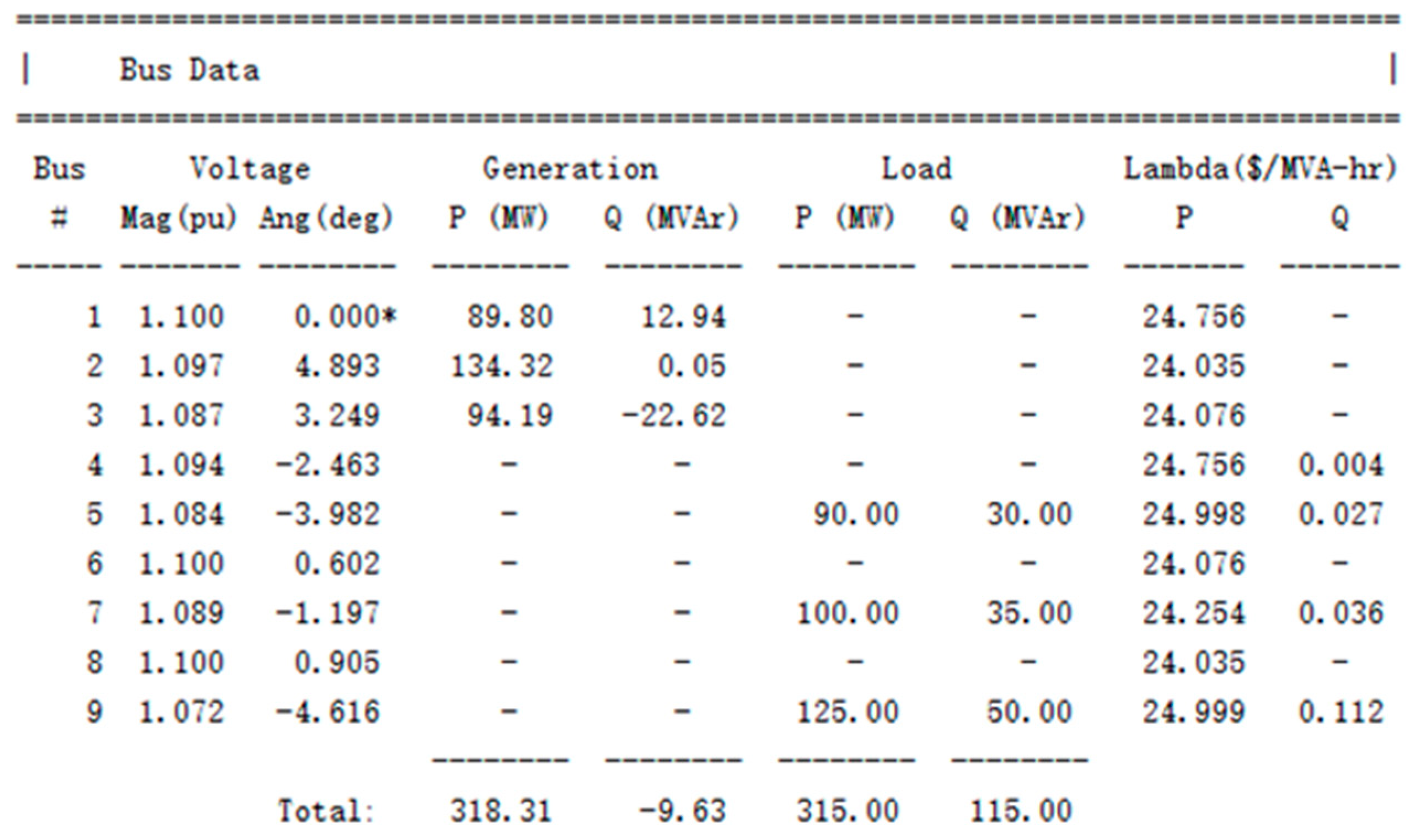
The standard case 9 test case from MATPOWER 8.0 is selected, with the objective function set to minimizing system operating cost, i.e., minimizing the active power output of generating units under fixed fuel prices. This paper uses MATPOWER 8.0, which was developed by the Power Systems Engineering Research Center (PSERC) at Cornell University, Ithaca, NY, USA.
The AOE control strategy network for optimal power flow calculation consists of four nodes: start node 1, computation node 2, assignment node 3, and end node 4. The action executed on edge 2–3 is a nonlinear programming task for solving the optimal power flow, while edge 3–4 performs an assignment operation used to display the optimal power flow calculation results.
The results obtained by executing the AOE network are shown in
Appendix A,
Table A1. In this table, voltage angles are expressed in radians, and power values are in per unit (p.u.), which must be multiplied by the base value of 100 MW to obtain physical units. The results computed by MATPOWER 8.0 are shown in
Appendix A,
Figure A1, where the voltage angles are expressed in degrees. A comparison shows that the two sets of results are consistent, thereby verifying the computational accuracy of the edge agent based on automatic differentiation.
5. Web Application Technology for Edge Agents
The deployment of edge agents requires deep coupling with the underlying hardware architecture, and their design must follow the principles of high performance and lightweight implementation to adapt to heterogeneous edge computing resources and the constraints of real-time response and power sensitivity. To this end, the edge agent adopts a microservice architecture for backend development and uses a web application frontend developed in WebAssembly. Both frontend and backend are implemented in Rust to enable unified full-stack programming and improve code reuse, thereby enhancing system operational efficiency.
5.1. Database Technology for Edge Agents
Embedded database technology is used for data storage and management, with access control handled by the application itself, eliminating the need for a separately deployed database server. Embedded databases are customizable, lightweight, and integrated within the process, making them suitable for embedded systems. In this paper, the open-source arbitrary binary K-V (key-value, key-value pair) data storage engine RocksDB is adopted as the embedded database implementation for the edge agent.
The data structure and management method of RocksDB are introduced as follows. RocksDB has three types of data structures: (1) mentable, a memory data structure, where all write requests enter; (2) logfile, an ordered write storage structure, where write requests enter selectively; and (3) sstfile, when the mentable is full, data enter the sstfile and are stored, and the related logfile is safely deleted. The data in the sstfile are sorted, so that they can be quickly searched based on the key. In terms of data management, RocksDB stores data as binary key-value pairs and supports sharding of a database instance by column families. RocksDB organizes all data in sequence and can specify compression algorithms to sort the key-value pairs. Common operations include retrieving a value by key (Get), inserting a key-value pair (Put), deleting a key-value pair (Delete), and iteration (Iter).
Compared with traditional storage solutions that use high-capacity servers to store raw text and other files, embedded databases offer higher reliability and stronger low-level control capabilities. They can operate stably and reliably over long periods without human intervention and are capable of directly interacting with underlying hardware devices. The use of embedded databases eliminates the overhead of client-server architecture, resulting in more compact code, faster execution speed, and improved performance when running in embedded environments.
5.2. Asynchronous Non-Blocking Communication Technology
In various edge computing scenarios, reliable acquisition of measurement data from devices is a prerequisite for controlling them. Distribution networks contain a wide range of complex device types, requiring the edge agent to support parallel data acquisition from different devices using multiple communication protocols and to standardize and store the collected data.
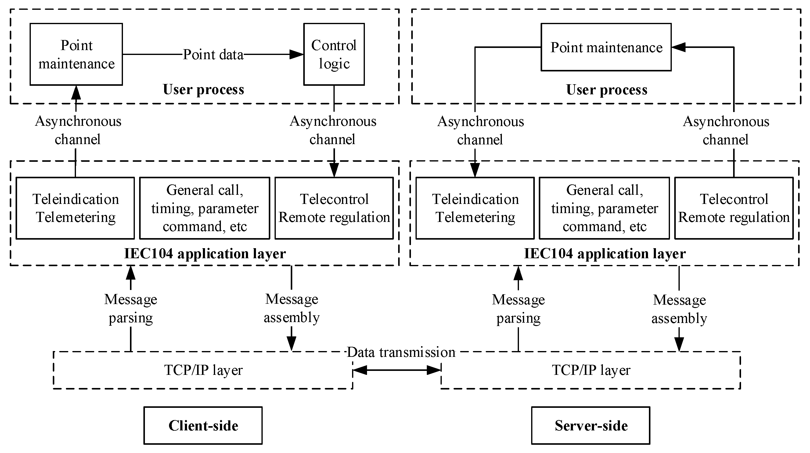
The edge agent application adopts asynchronous non-blocking technology to implement communication gateways for the power Internet of Things, supporting multiple protocols including IEC 104, Modbus, DL/T645, and MQTT. Taking the non-blocking implementation of the IEC 104 protocol as an example, the protocol is designed with a three-layer structure: TCP/IP layer, application layer, and user process.
Based on the Tokio asynchronous framework, a non-blocking I/O network communication framework is developed, covering client connection, server listening and connection, and read/write method design, enabling data exchange over lower-layer TCP/IP connections. Asynchronous channels are used to support information sharing and command transmission between the application layer and the user process. In the application layer, asynchronous tasks are used to implement IEC 104 protocol functions such as link transmission rules, message parsing and assembly, and application functionalities. The overall structure and data flow of IEC 104 are shown in
Figure 3.
In the asynchronous non-blocking communication framework described above, the underlying non-blocking network communication effectively conserves hardware resources and enhances the parallel processing capability of multi-channel communication. The user process standardizes the collected data from each channel, converting them into a unified measurement point format, which enables consistent computation and logical analysis across data from different devices using a generalized approach. By decoupling data acquisition from data processing, each stage operates in parallel, improving overall data flow and processing speed.
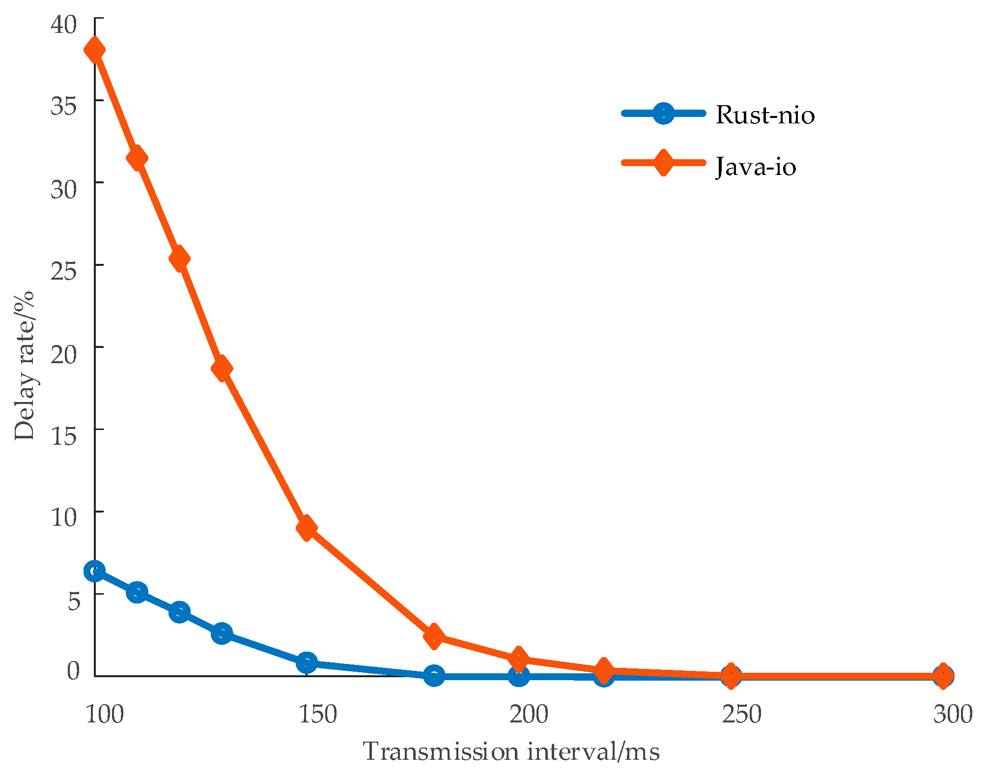
Consistency and performance tests were conducted on the communication system developed using this framework. As shown in
Figure 4, under high communication load, the delay rate of the proposed method is significantly lower than that of traditional solutions. This verifies that the developed communication application can complete data transmission in accordance with protocol specifications. Based on asynchronous non-blocking technology, the edge agent can still ensure the accuracy and real-time performance of communication data on resource-constrained embedded devices.
6. Station-Level Optimal Dispatch in Distribution Networks Based on Distributed Edge Agents
This section verifies the distributed control technology of edge agents using the economic dispatch of distribution network stations. First, a station-level economic optimization dispatch model based on a discrete consensus algorithm is designed. Then, a digital twin of the actual system is simulated, and the distributed control performance of the edge agents is analyzed.
6.1. Economic Dispatch Optimization Model for Stations
To achieve economic optimality in a station, the total generation cost within the station’s jurisdiction should be minimized. The generation cost
Ci of the distributed generation unit at bus
i in the station can be approximated by a quadratic function [
44], as shown below.
where
ai,
bi, and
ci represent the cost coefficients of the distributed generation unit, and
Pi represents the actual active power output of the unit.
Given that the bus voltage remains stable under actual station operating conditions and the deviation is negligible, the actual active power output
Pi (in p.u.) of the distributed generation unit is approximately equivalent to its output current
Ii (in p.u.) [
45]. Accordingly, Equation (11) can be rewritten as
Based on Equation (12), an economic dispatch optimization model for the station is constructed. Considering the power transfer requirements among the buses within the station, in addition to satisfying the station power balance equation and the output current constraints of the distributed generation units, corresponding voltage constraints are formulated. The arithmetic mean of bus voltages is used as the reference value. The objective function and constraints are defined as follows:
where
Li represents the load current injected at bus
I;
represents the maximum output current of the distributed generation unit at bus
I;
Ui represents the measured voltage at bus
i; and
Umean represents the reference value of the bus voltage.
6.2. Mathematical Design of Control Strategy
Based on Lagrangian duality theory, the optimization functional of the station economic dispatch model is constructed. Through gradient conditions and the first-order optimality conditions of the Karush–Kuhn–Tucker (KKT) framework, it is analytically derived that the total generation cost of the station reaches its minimum when the marginal costs at all buses are equal. The corresponding expression is
Define λi = ∂Ci/∂Ii as the marginal cost at bus i. Considering the property of multi-agent systems to achieve state consensus through distributed information exchange, a distributed consensus computation framework is constructed using marginal cost as the consensus state variable. Under this framework, each agent iteratively updates its marginal cost until convergence is achieved. For bus i, the control steps are as follows.
Step 1: Initialization. When the economic dispatch task is initiated, the edge agent acquires bus information and calculates the marginal cost
λi[
k] of bus
i at time step
k as well as the marginal cost deviation
μi[
k] with respect to its topological neighboring buses. The calculations are as follows:
where
gij represents the element in the
i-th row and
j-th column of the nodal conductance matrix
G.
Li represents the set of topological neighboring buses of bus
i.
Step 2: Determine iteration status. If the event trigger condition defined in Equation (17) is satisfied [
46], proceed to Step 3; otherwise, maintain the current state until the next time step and terminate the task.
where
ei[
k] represents the event-triggered marginal cost stored at bus
i at time step
k; and
σ and
ε represent error coefficients, where 0 <
σ < 1. To ensure that Equation (17) remains non-negative, it must also satisfy 0 <
ε < 1/
G(
i,
i).
Step 3: Update the event-triggered marginal cost, calculate the voltage adjustment value for bus
i at time step
k + 1, and issue the control command to complete the task.
where
q represents the step-size coefficient. To ensure control stability, it must satisfy 0 <
q < 1/
λAnλ2Gn [
47], where
λAn is the maximum value among all cost coefficients
ai, and
λGn represents the largest eigenvalue of the conductance matrix
G.
6.3. Strategy Description Based on Control Configuration Technology
The operational states and dynamic responses in the control steps of
Section 6.2 are defined as events and actions, respectively. Combined with control configuration technology, the control steps can be described using an AOE structure, as shown in
Figure 5. Taking bus 1 as an example, the configuration expressions for each event and action are provided in
Appendix B, thereby completing the control strategy design.
Specifically, node 1 is the start node with an EventDriven trigger type. When the agent receives the start command, Start_command1, the strategy is initiated, and edge 1–2 is executed to calculate the marginal cost and deviation based on Equations (15) and (16). Node 2 is a switch-type event node; if the condition is satisfied, the process proceeds to node 4; otherwise, it jumps to termination node 3 to exit the process. Then, actions on edges 2–4 and 4–5 are executed, corresponding to Step 3 in
Section 6.2. After completion, the process reaches end node 5, closing the AOE-based control loop.
6.4. Simulation Analysis
6.4.1. Station Simulation Environment Construction
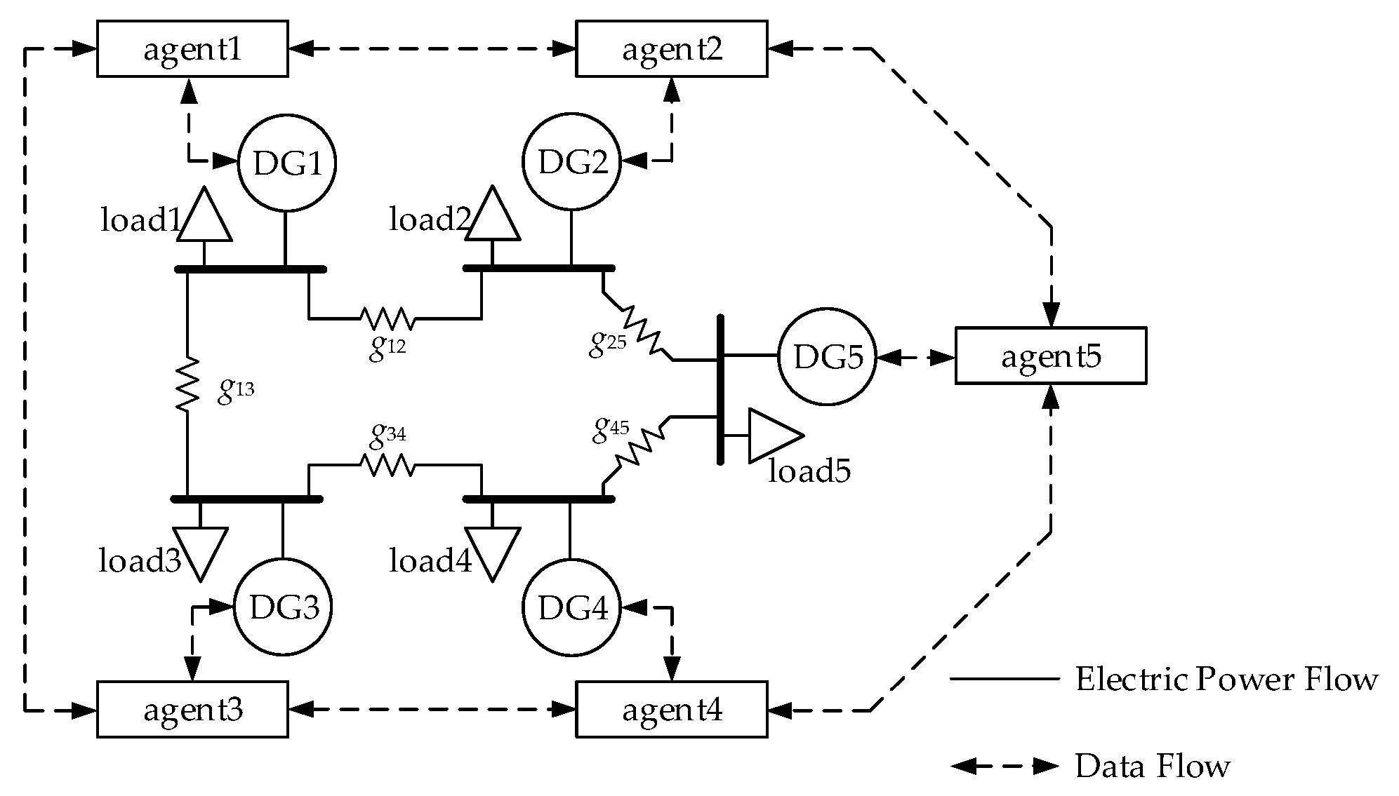
A digital twin model of a five-bus station system in a distribution network is constructed in Simulink to simulate real-time economic dispatch at the station level. The topology of the five-bus station is shown in
Figure 6, and the corresponding parameters are listed in
Appendix C. The simulation model is built using Simulink 10.2 in MATLAB 2020b, and the simulation is run on a computer equipped with an Intel(R) i7-8700 processor and 16 GB of RAM.
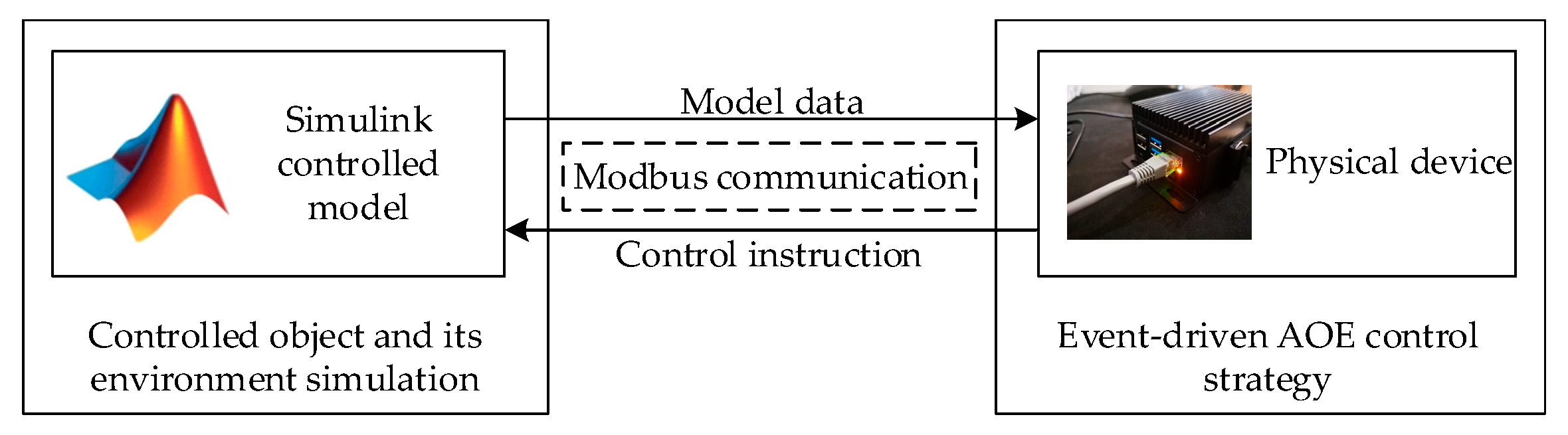
Figure 7 shows the hardware-in-the-loop simulation architecture between the edge agent and Simulink. The edge agent is deployed on hardware and is responsible for collecting model data, executing the AOE control strategy, and sending control commands to the Simulink model. In Simulink, Modbus communication with each edge agent is implemented using the S-Function module, which serves as the control module in the model, linking the input signals from data acquisition and the output signals for control commands. The hardware device used in this study is equipped with an ARMV7 CPU, 2 GB of RAM, and a 4 GB hard drive.
6.4.2. Economic Dispatch Results and Analysis
Figure 8 shows the simulation results of station-level economic dispatch, where the dispatch task is initiated at 1 s. It can be observed that after each load fluctuation, the edge agents dynamically adjust the output power of the distributed generation units by modifying the marginal cost. The marginal costs quickly converge to a common value, thereby achieving economic optimality. Additionally, when the load at bus 1 exceeds 1 p.u., the edge agents are able to control other buses to support bus 1, ensuring that the DG output at bus 1 does not exceed its upper limit. Throughout the control process, the average voltage across all five buses remains at the rated level, demonstrating the effectiveness of the proposed distributed control algorithm.
6.4.3. Comparison of Dispatch Trigger Frequency
During the operation of control systems, frequent communication and repetitive computation often lead to waste of computational resources and device energy, which has become a major bottleneck for the large-scale deployment of edge agents. In the context of distribution networks, if edge agents communicate too frequently, resource exhaustion may occur, posing a serious threat to the stable operation of the system.
Figure 9 shows the number of event triggers for each edge agent during the distributed control process at the edge.
When event-driven control is adopted, the number of triggers for the five edge agents is 2119, 2147, 1907, 1942, and 2006, respectively. Without event-driven control, each edge agent is triggered 3251 times. The comparison shows that the trigger counts at each node are reduced by 34.82%, 33.96%, 41.34%, 40.26%, and 40.26%, respectively. When Equation (17) is not satisfied, the edge agent does not trigger the task, significantly reducing the number of activations. This demonstrates that edge-based distributed control effectively reduces unnecessary task triggering, improves the efficiency of concurrent task execution, and achieves better real-time control performance.
6.4.4. Dispatch Efficiency Comparison
Using traditional centralized control as a baseline, the efficiency of the proposed edge-based distributed control is compared, as shown in
Table 2. It can be observed that, compared to centralized control, the edge-based distributed approach significantly reduces communication latency by leveraging the geographically proximal deployment of edge agents, thereby shortening the data upload and command transmission paths. Although distributed control introduces additional parallel processing overhead due to multi-node coordination, its localized decision-making mechanism avoids the data aggregation bottleneck inherent in centralized systems. Overall, the edge-based distributed control method responds more quickly to changes in distribution network conditions and demonstrates superior global responsiveness in dynamic scenarios.
Furthermore, an economic dispatch control strategy for a distribution network station with a larger number of nodes is constructed and computed. As the number of nodes increases, the computation times required for strategy execution using the traditional centralized control method and the proposed edge-based distributed control method are shown in
Table 3.
The computation time increases when using the centralized control method, while it remains nearly constant when using the edge-based distributed control method. This is because, in edge-based distributed control, each edge agent only communicates with directly connected agents, resulting in smaller computation scales and immunity to increasing network complexity. In contrast, with the centralized control method, as the number of nodes increases, both the communication network and the computation scale expand, leading to longer strategy computation times.
7. Discussion
In recent years, edge agent technology has been gradually applied in distributed control of power distribution networks, but several key challenges remain. First, most existing edge control schemes are designed for specific scenarios and thus struggle to accommodate the broad adaptability required for managing heterogeneous multi-source resources. Second, many methods lack a structured representation of control logic, making it difficult to support modular configuration and reuse. Moreover, in typical emerging scenarios, edge nodes must respond to frequent state changes, which can lead to communication congestion and compromise system stability under resource-constrained conditions.
To address these challenges, this paper proposes a control configuration method oriented toward modular deployment. Specifically, an activity-on-edge model is employed to abstract control logic, explicitly representing the execution sequence and triggering relationships of control flows. By incorporating hybrid control theory, discrete events and continuous dynamics are unified within a structured framework. This approach improves the reusability and adaptability of control logic across diverse application scenarios.
At the execution level, a web-based edge agent architecture is adopted, integrating event-driven control with automatic differentiation-based optimization. The event-driven mechanism activates control only when predefined conditions are met, effectively improving responsiveness and resource efficiency in dynamic environments. Automatic differentiation avoids symbolic expression expansion and enables fast computation of high-dimensional gradients. By introducing web application technology, the frontend and backend of the system are decoupled to improve module reuse and execution efficiency. In addition, asynchronous communication enables non-blocking data exchange between agents, ensuring timely information delivery and supporting the real-time responsiveness required in distributed control systems.
Despite these advantages, the proposed method still has some limitations. The current framework assumes relatively stable edge hardware and communication conditions, while in real-world deployments, device heterogeneity and unstable communication links may affect coordination among agents. Furthermore, the event-driven mechanism is sensitive to parameter settings, and inappropriate parameter selection may lead to delayed responses or frequent triggering, negatively affecting overall system performance.
Looking ahead, the proposed method offers strong scalability and integration potential. The edge agent architecture can be further integrated with IoT-based sensing platforms or extended to coordinate flexible loads such as electric vehicles with dynamic charging behavior. Future work will focus on validating the proposed method in more complex and diverse distribution network scenarios to further improve and refine its performance.
8. Conclusions
This paper proposes a distributed edge agent technology for distribution networks with several key contributions. First, a highly adaptable edge agent control architecture is designed based on hybrid control theory, considering the diverse requirements of distributed control in distribution networks. Furthermore, a control configuration technology suitable for edge agents is proposed, enabling standardized configuration of distribution network tasks. This facilitates fast and lightweight deployment, as well as flexible updates, of event-driven control strategies. In addition, by taking economic optimization dispatch at the station level as a representative edge computing application, the proposed edge-based distributed control method is compared with traditional centralized control. The results validate the effectiveness of the proposed approach, which demonstrates advantages such as low communication latency and reduced computation scale, making it suitable for large-scale distribution network control scenarios
Author Contributions
Methodology: X.Z., Y.L., S.G., Y.T. and Y.G.; writing—original draft preparation: X.Z. and Y.G.; writing—review and editing: X.Z., Y.L., S.G., Y.T. and Y.G. All authors have read and agreed to the published version of the manuscript.
Funding
This research was supported by the Science & Technology Project of State Grid Corporation of China, “Research on Key Technologies of Distributed Collaborative Computing and Control for New-Type Distribution Networks” (Project Code: 5400-202356680A-3-3-JC).
Data Availability Statement
The original contributions presented in the study are included in the article, and further inquiries can be directed to the corresponding author.
Acknowledgments
The authors sincerely acknowledge the contribution of all individuals, reviewers, and editors for their contribution toward the production of this manuscript.
Conflicts of Interest
Authors Xianglong Zhang, Ying Liu, Songlin Gu, Yuzhou Tian, and Yifan Gao are affiliated with State Grid Economic and Technological Research Institute Co., Ltd.. The authors declare that the research was conducted in the absence of any commercial or financial relationships that could be construed as potential conflicts of interest.
Abbreviations
The following abbreviations are used in this manuscript:
| AOE | Activity-on-edge network |
| MILP | Mixed-Integer Linear Programming |
| NLP | Nonlinear programming |
Appendix A
Table A1.
Operation results of the optimal power flow calculation case.
Table A1.
Operation results of the optimal power flow calculation case.
| Serial Number | Point Number | Name | Another Name | Current Value |
|---|
| 1 | 1001 | Point1 | V1 | 1.099999920539086 |
| 2 | 1002 | Point2 | V2 | 1.0973546514586485 |
| 3 | 1003 | Point3 | V3 | 1.0866203282032385 |
| 4 | 1004 | Point4 | V4 | 1.094221462595771 |
| 5 | 1005 | Point5 | V5 | 1.084448462899668 |
| 6 | 1006 | Point6 | V6 | 1.1000000109999306 |
| 7 | 1007 | Point7 | V7 | 1.0894894953643341 |
| 8 | 1008 | Point8 | V8 | 1.1000000109967762 |
| 9 | 1009 | Point9 | V9 | 1.0717554151378195 |
| 10 | 1010 | Point10 | THETA1 | 0.0000000000000000 |
| 11 | 1011 | Point11 | THETA2 | 0.0854101800932149 |
| 12 | 1012 | Point12 | THETA3 | 0.05671518263242919 |
| 13 | 1013 | Point13 | THETA4 | −0.04298613947999122 |
| 14 | 1014 | Point14 | THETA5 | −0.06949871348651646 |
| 15 | 1015 | Point15 | THETA6 | 0.010522383653749938 |
| 16 | 1016 | Point16 | THETA7 | −0.020878902993962594 |
| 17 | 1017 | Point17 | THETA8 | 0.015806264325692185 |
| 18 | 1018 | Point18 | THETA9 | −0.0805511204216152 |
| 19 | 1019 | Point19 | PG1 | 0.8979870754479929 |
| 20 | 1020 | Point20 | PG2 | 1.3432060080841293 |
| 21 | 1021 | Point21 | PG3 | 0.9418738048899336 |
| 22 | 1022 | Point22 | QG1 | 0.1296559578027687 |
| 23 | 1023 | Point23 | QG2 | 0.0003187190823897824 |
| 24 | 1024 | Point24 | QG3 | −0.22634181614061613 |
| 25 | 1025 | Point25 | Docal_POINT | 0 |
Figure A1.
Operation results of MATPOWER 8.0.(* indicates that the bus is the slack bus).
Figure A1.
Operation results of MATPOWER 8.0.(* indicates that the bus is the slack bus).
Appendix B
Table A2.
Node event configuration representation.
Table A2.
Node event configuration representation.
| Node Name | Event Type | Expression |
|---|
| Business start judgment | Condition | Start_command1 > 0 |
| Iteration state judgment | Switch | (triggerE1 − lambd1)2 − (sigma * epsilon * miu12 * (1 − 2 * epsilon * G1[1])/2 * G1[1]) > 0 |
| Transition node | Condition | 1 |
| Adjustment state end node | Condition | 1 |
| Holding state end node | Condition | 1 |
Table A3.
Action configuration representation.
Table A3.
Action configuration representation.
| Start and End Nodes | Action Definition | Expression |
|---|
| 1:2 | Marginal cost and
deviation calculation | lambd1:a1 * I1 + b1;
miu1:G1[2] * (labmd1 − lambd2) +
G1[3] * (labmd1 − lambd3) +
G1[4] * (labmd1 − lambd4); |
| 2:3 | No-action event | \ |
| 2:4 | Update of event-triggered marginal cost | triggerE1:lambd1; |
| 4:5 | Command calculation and issuance | V1:V1 − q * miu1; |
Appendix C
Table A4.
Station parameters.
Table A4.
Station parameters.
| Parameters | Value |
|---|
| a1, a2, a3, a4, a5/10−2 p.u. | 4.175, 2.675, 2.675, 2.675, 5.025 |
| b1, b2, b3, b4, b5/10−4 p.u. | 5.889, 5.841, 5.841, 5.841, 6.003 |
| c1, c2, c3, c4, c5/10−3 p.u. | 8.060, 7.576, 7.576, 7.576, 8.560 |
| g12, g13, g25, g34, g45/p.u. | 4, 5, 4, 5, 4 |
| Umean/V, Imax,i/p.u. | 400, 1 |
Table A5.
Node load parameters.
Table A5.
Node load parameters.
| Node ID | Load Value/p.u. |
|---|
| 0–3 s | 3–5 s | 5–7 s |
|---|
| 1 | 0.55 | 1.00 | 0.60 |
| 2 | 0.75 | 0.85 | 0.60 |
| 3 | 0.60 | 0.70 | 0.60 |
| 4 | 0.65 | 0.70 | 0.55 |
| 5 | 0.55 | 0.60 | 0.55 |
Table A6.
Consensus algorithm parameters.
Table A6.
Consensus algorithm parameters.
| Parameters | Value |
|---|
| σ | 10−6 |
| ε | 0.03 |
| q | 0.02 |
References
- Lu, P.; Lan, H.; Yuan, Q.; Jiang, Z.; Cao, S.; Ding, J.; Wei, Q.; Fan, J.; Cai, Q.; Zhang, N.; et al. A Bi-Level Solution Strategy Based on Distributed Proximal Policy Optimization for Transmission and Distribution Network Dispatch with EVs and Variable Energy. Appl. Energy 2025, 384, 125405. [Google Scholar] [CrossRef]
- Huang, Q.; Cheng, H.; Zhuang, Z.; Duan, M.; Fang, K.; Huang, Y.; Wang, L. Distributed Dispatch of Distribution Network Operators, Distributed Energy Resource Aggregators, and Distributed Energy Resources: A Three-Level Conditional Value-at-Risk Optimization Model. Inventions 2024, 9, 117. [Google Scholar] [CrossRef]
- Iftikhar, M.Z.; Imran, K. Network Reconfiguration and Integration of Distributed Energy Resources in Distribution Network by Novel Optimization Techniques. Energy Rep. 2024, 12, 3155–3179. [Google Scholar] [CrossRef]
- Gao, X.; Xu, H.; Zhao, X.; Gao, S.; Xie, H.; Zhang, N.; Li, Q.; Yang, Y. Dispatching of Distribution Networks with High Permeability Distributed New Energy Based on Phase Shifting Transformer Loop-Closing Device. Front. Energy Res. 2025, 13, 1516459. [Google Scholar] [CrossRef]
- Caballero-Peña, J.; Cadena-Zarate, C.; Parrado-Duque, A.; Osma-Pinto, G. Distributed Energy Resources on Distribution Networks: A Systematic Review of Modelling, Simulation, Metrics, and Impacts. Int. J. Electr. Power Energy Syst. 2022, 138, 107900. [Google Scholar] [CrossRef]
- Xu, X.; Zhao, N.; Wang, L.; Yao, X.; Zhou, L. Research on Time-Varying Dynamic Response Aggregation Model of Distributed Generator Participating in Active Distribution Network. Energy Rep. 2023, 9, 1546–1556. [Google Scholar] [CrossRef]
- Varathan, G.; Belwin Edward, J. A Review of Uncertainty Management Approaches for Active Distribution System Planning. Renew. Sustain. Energy Rev. 2024, 205, 114808. [Google Scholar] [CrossRef]
- Chen, Y.; Hayawi, K.; Fan, M.; Chang, S.Y.; Tang, J.; Yang, L.; Zhao, R.; Mao, Z.; Wen, H. A Bilevel Optimization Model Based on Edge Computing for Microgrid. Sensors 2022, 22, 7710. [Google Scholar] [CrossRef]
- Wenzhi, S.; Zhang, H.; Tseng, M.-L.; Weipeng, Z.; Xinyang, L. Hierarchical Energy Optimization Management of Active Distribution Network with Multi-Microgrid System. J. Ind. Prod. Eng. 2022, 39, 210–229. [Google Scholar] [CrossRef]
- Ahrens, M.; Kern, F.; Schmeck, H. Strategies for an Adaptive Control System to Improve Power Grid Resilience with Smart Buildings. Energies 2021, 14, 4472. [Google Scholar] [CrossRef]
- Thenmozhi, T.; Suganyadevi, M.V.; Ramya, R.; Muthukumar, P. Hybrid Energy Management on Electric Vehicles for Power Grids with Renewables System. Environ. Chall. 2022, 9, 100647. [Google Scholar] [CrossRef]
- Aslam, M.M.; Lateef, U.; Khalid, Z.; Saleem, U.; Liu, W.; Li, W. Energy Management in Smart Grids: Innovative Solutions for Demand-Side Optimization Considering Control Constraints. In Proceedings of the 2024 3rd International Conference on Emerging Trends in Electrical, Control, and Telecommunication Engineering (ETECTE), Lahore, Pakistan, 26–27 November 2024; pp. 1–6. [Google Scholar]
- Rubino, L.; Rubino, G.; Esempio, R. Linear Programming-Based Power Management for a Multi-Feeder Ultra-Fast DC Charging Station. Energies 2023, 16, 1213. [Google Scholar] [CrossRef]
- Feng, J.; Ran, L.; Wang, Z.; Zhang, M. Optimal Bidding Strategy for Virtual Power Plant in Multiple Markets Considering Integrated Demand Response and Energy Storage. J. Energy Storage 2025, 124, 116706. [Google Scholar] [CrossRef]
- Chen, Y.; Liu, Y.; Shen, X.; Xu, L.; Liu, J.; Li, L. Review of Edge Intelligence Technology for Distributed Energy Resources in Urban Energy Systems. Autom. Electr. Power Syst. 2022, 46, 142–152. [Google Scholar] [CrossRef]
- Shen, S.; Ren, Y.; Ju, Y.; Wang, X.; Wang, W.; Leung, V.C.M. EdgeMatrix: A Resource-Redefined Scheduling Framework for SLA-Guaranteed Multi-Tier Edge-Cloud Computing Systems. IEEE J. Sel. Areas Commun. 2023, 41, 820–834. [Google Scholar] [CrossRef]
- Liu, Z.; Song, J.; Qiu, C.; Wang, X.; Chen, X.; He, Q.; Sheng, H. Hastening Stream Offloading of Inference via Multi-Exit DNNs in Mobile Edge Computing. IEEE Trans. Mob. Comput. 2024, 23, 535–548. [Google Scholar] [CrossRef]
- Nie, Y.; Peng, C.; Hu, Y.; He, Y.; Ma, G.; Huang, C. Parallel distributed optimal economic dispatch of High penetration microgrid based on edge computing. South. Power Syst. Technol. 2023, 17, 114–124. [Google Scholar] [CrossRef]
- Jie, T.; Qi, Z.; Pu, T.; Song, R.; Zhang, J.; Tan, Y.; Wang, X. Edge Intelligence in Power Internet of Things: Concept, Architecture, Technology and Application. Proc. CSEE 2024, 44, 5473–5496. [Google Scholar] [CrossRef]
- Zhang, D.; Li, X.; Tao, W. Location of single-phase grounding fault segment in limited information distribution network based on edge computing and deep learning. Power Syst. Prot. Control 2023, 51, 22–32. [Google Scholar] [CrossRef]
- Qin, Q.; Liu, W.; Tan, W.; Cai, Z.; Cen, B.; Kuang, P. Optimal deployment method of distribution edge computing terminal for software defined network. Electr. Power Constr. 2023, 44, 82–90. [Google Scholar] [CrossRef]
- Pan, S.; Liu, B. Optimal allocation method of edge computing unit for fast Fault processing of distribution network. Electr. Power Constr. 2022, 43, 31–41. [Google Scholar] [CrossRef]
- Liu, D.; Zeng, X.; Wang, Y. Control Strategy of virtual power station in Distribution area based on Edge Computing Architecture. Trans. China Electrotech. Soc. 2021, 36, 2852–2860. [Google Scholar] [CrossRef]
- Yuan, L.; Gu, J.; Jin, Z. User-side data application framework of Power Internet of Things based on Cloud-edge-end collaboration. Electr. Power Constr. 2020, 41, 1–8. [Google Scholar] [CrossRef]
- Hinton, G.; Vinyals, O.; Dean, J. Distilling the Knowledge in a Neural Network. Comput. Sci. 2015, 14, 38–39. [Google Scholar] [CrossRef]
- Mao, Y.; Zhang, J.; Letaief, K.B. Dynamic Computation Offloading for Mobile-Edge Computing with Energy Harvesting Devices. IEEE J. Sel. Areas Commun. 2016, 34, 3590–3605. [Google Scholar] [CrossRef]
- You, C.; Huang, K.; Chae, H.; Kim, B.-H. Energy-Efficient Resource Allocation for Mobile-Edge Computation Offloading. IEEE Trans. Wirel. Commun. 2017, 16, 1397–1411. [Google Scholar] [CrossRef]
- Zhang, K.; Mao, Y.; Leng, S.; Zhao, Q.; Li, L.; Peng, X.; Pan, L.; Maharjan, S.; Zhang, Y. Energy-Efficient Offloading for Mobile Edge Computing in 5G Heterogeneous Networks. IEEE Access 2016, 4, 5896–5907. [Google Scholar] [CrossRef]
- Krizhevsky, A.; Sutskever, I.; Hinton, G.E. ImageNet Classification with Deep Convolutional Neural Networks. Commun. ACM 2017, 60, 84–90. [Google Scholar] [CrossRef]
- Hu, W.; Lu, Q. Hybrid Power Control System and Its Application. Trans. China Electrotech. Soc. 2005, 20, 11–16. [Google Scholar] [CrossRef]
- Liu, G.; Park, J.H.; Hua, C.; Li, Y. Hybrid Dynamic Event-Triggered Load Frequency Control for Power Systems with Unreliable Transmission Networks. IEEE Trans. Cybern. 2023, 53, 806–817. [Google Scholar] [CrossRef]
- Dou, C.; Teng, S.; Zhang, T.; Zhang, B.; Ma, K. Layered Management and Hybrid Control Strategy Based on Hybrid Automata and Random Forest for Microgrid. IET Renew. Power Gener. 2019, 13, 3113–3123. [Google Scholar] [CrossRef]
- Liu, F.; Zhang, Y.; Meng, D.; Zhu, P. Voltage hybrid control of microgrid. J. Henan Univ. Sci. Technol. 2017, 38, 49–53, 59, 118. [Google Scholar] [CrossRef]
- Zhang, C.; Xu, Y.; Dong, Z.Y.; Zhang, R. Multi-Objective Adaptive Robust Voltage/VAR Control for High-PV Penetrated Distribution Networks. IEEE Trans. Smart Grid 2020, 11, 5288–5300. [Google Scholar] [CrossRef]
- Li, Y.; Li, K.; Fan, R.; Chen, J.; Zhao, Y. Multi-Objective Planning of Distribution Network Based on Distributionally Robust Model Predictive Control. Front. Energy Res. 2024, 12, 1478040. [Google Scholar] [CrossRef]
- Zhang, J.; Tang, Y.; Wang, J.; Lv, D.; Zhu, L.; Dong, F. Simulation-Based Joint User Assignment and Edge Resource Allocation Optimization for Hybrid Tasks in Vehicular Edge Computing. Simul. Model. Pract. Theory 2023, 128, 102810. [Google Scholar] [CrossRef]
- Lan, Y.; Wang, X.; Wang, C.; Wang, D.; Li, Q. Collaborative Computation Offloading and Resource Allocation in Cache-Aided Hierarchical Edge-Cloud Systems. Electronics 2019, 8, 1430. [Google Scholar] [CrossRef]
- Shi, B.; Zhao, M.; Yu, Z.; Yuan, L.; Chen, K.; Ji, S. Development status and prospect of power electronics Simulation technology and simulation software based on discrete state events. Proc. CSEE 2022, 42, 6005–6016. [Google Scholar] [CrossRef]
- Zhang, M.; Lu, Q. Hybrid Control System for Super Energy Management System of China Southern Power Grid. Power Grid Technol. 2007, 31, 5–9. [Google Scholar] [CrossRef]
- Ahmad, Z.; Abbasi, M.H.; Khan, A.; Mall, I.S.; Khan, M.F.N.; Sajjad, I.A. Design of IoT Embedded Smart Energy Management System. In Proceedings of the 2020 International Conference on Engineering and Emerging Technologies (ICEET), Lahore, Pakistan, 22–23 February 2020; pp. 1–5. [Google Scholar] [CrossRef]
- Li, C. Research on Automatic Differentiation Implementation and Optimization Algorithm Based on Source Code Conversion. Master’s Thesis, Beijing Jiaotong University, Beijing, China, 2022. [Google Scholar]
- Margossian, C.C. A Review of Automatic Differentiation and Its Efficient Implementation. WIREs Data Min. Knowl. Discov. 2019, 9, e1305. [Google Scholar] [CrossRef]
- Coleman, T.F.; Verma, A. The Efficient Computation of Sparse Jacobian Matrices Using Automatic Differentiation. SIAM J. Sci. Comput. 1998, 19, 1210–1233. [Google Scholar] [CrossRef]
- Yu, Z. Research on Source-Load Distributed Cooperative Optimized Operation of Active Distribution Network. Master’s Thesis, Northeastern University, Shenyang, China, 2024. [Google Scholar]
- Peng, J.; Fan, B.; Liu, W. Voltage-Based Distributed Optimal Control for Generation Cost Minimization and Bounded Bus Voltage Regulation in DC Microgrids. IEEE Trans. Smart Grid 2021, 12, 106–116. [Google Scholar] [CrossRef]
- Dimarogonas, D.V.; Frazzoli, E.; Johansson, K.H. Distributed Event-Triggered Control for Multi-Agent Systems. IEEE Trans. Autom. Control 2012, 57, 1291–1297. [Google Scholar] [CrossRef]
- Xu, Y.; Liu, W. Novel Multiagent Based Load Restoration Algorithm for Microgrids. IEEE Trans. Smart Grid 2011, 2, 152–161. [Google Scholar] [CrossRef]
| Disclaimer/Publisher’s Note: The statements, opinions and data contained in all publications are solely those of the individual author(s) and contributor(s) and not of MDPI and/or the editor(s). MDPI and/or the editor(s) disclaim responsibility for any injury to people or property resulting from any ideas, methods, instructions or products referred to in the content. |
© 2025 by the authors. Licensee MDPI, Basel, Switzerland. This article is an open access article distributed under the terms and conditions of the Creative Commons Attribution (CC BY) license (https://creativecommons.org/licenses/by/4.0/).


