1. Introduction
Tire vulcanization molding is a key process in tire production, which has a direct impact on the performance and quality of tires. The temperature uniformity of the hot plate surface of the vulcanizing machine is one of the most important performance indicators, which directly affects the temperature distribution on the mold surface and thus has a significant impact on the damping, stiffness, and compression performance of the rubber [
1]. The traditional vulcanization method mainly relies on steam or hot water heating medium, which has the problems of high energy consumption, low efficiency, and difficult temperature control, resulting in uneven temperature during the vulcanization process [
2,
3]. In recent years, electromagnetic heating technology has become an emerging technology for improving tire vulcanization uniformity and energy efficiency due to its rapid heating and precise temperature control characteristics [
4,
5]. Electromagnetic heating generates eddy currents through an alternating magnetic field, which has high heating efficiency and can effectively compensate for the energy loss in traditional heating methods. It has gradually been promoted in the field of rubber vulcanization [
6]. Heat transfer plays a crucial role in the molding quality and production efficiency of rubber elastic components during the vulcanization process.
In recent years, a variety of optimization methods have been proposed by both academia and industry to address the problem of non-uniform temperature distribution on heating plates [
7]. These methods primarily focus on two aspects: the adjustment of heating parameters and innovation in coil structure. Some studies focus on exploring the optimal current intensity, current frequency, coil structure, and distance between hot plates to achieve optimal temperature uniformity [
8]. Orthogonal experimental design has been widely used to evaluate key factors such as heating frequency, current intensity, and coil-to-plate spacing [
9,
10,
11], aiming to reduce temperature gradients and enhance temperature control accuracy. Zhou [
12] obtained the importance ranking of the heating parameters that have an impact on the temperature field of the hot plate through orthogonal experiments: current frequency > current intensity > distance between hot plate and coil. While parameter tuning can partially reduce temperature differences, it often overlooks the effect of parameter changes on heating time and may not be applicable to irregularly shaped plates using conventional coil structures. Wang [
3] achieved improved temperature uniformity by designing combinatorial spiral coil arrangements; however, the resulting coil layout posed high complexity in both installation and control. Sun [
13] increased the local distance between the induction coil and the radiation surface by cutting the high- temperature area of the hot plate, thereby reducing the temperature in the high-temperature area. However, the application of the cutting heating model in actual production is impractical to some extent. Zhang [
14] established a 3D numerical model coupled with electromagnetic induction and studied the influence of factors such as coil to tube distance, coil power, and ambient temperature on heating efficiency. Talal [
15] used electromagnetic heating technology to improve the performance of metal hydride hydrogen storage tanks. The results showed that compared with traditional heat conduction liquid methods, the heating efficiency of electromagnetic heating increased by 87%. By increasing the number of turns per unit length of the coil, heating time can be significantly shortened. However, electromagnetic heating still faces many challenges in practical applications such as coil arrangement and magnetic field uniformity [
12,
16]. Currently, simplified models have been used in many electromagnetic heating simulations by abstracting coils as flat plates and simulating electromagnetic effects by adjusting the number of turns [
4,
17]. However, such models often neglect the influence of the actual coil geometry on the resulting temperature field, leading to discrepancies between simulation predictions and experimental measurements.
Based on the limitations of the above research and engineering needs, this paper proposes a multi-ring-petal-shaped composite coil electromagnetic induction heating scheme, which, combined with the structural characteristics of the octagonal hot plate, aims to significantly improve the temperature uniformity problem in the edge and corner regions of the hot plate through the optimization of the magnetic field distribution. Compared with the traditional uniformly distributed coils and simple combination coils, this structural design theoretically has better magnetic field coverage capability and temperature field control capability. In order to verify its feasibility and engineering application value, this paper constructs a simulation model consistent with the actual structure, carries out an experimental study combined with an industrial-grade hot plate prototype, discusses the performance of temperature control from the level of simulation and measurement, systematically evaluates the temperature control capability and stability of this method, and provides a theoretical basis and practical foundation for the further optimization of the subsequent hot plate structure.
2. Finite Element Simulation
2.1. Theoretical Analysis of Electromagnetic Heating
The key issue of electromagnetic heating is the generation of eddy currents in a conductor by means of an alternating magnetic field, resulting in rapid heating through the Joule effect. A system of Maxwell’s equations describes the behavior of the electromagnetic field and mainly consists of the following equations [
13]:
In electromagnetic heating problems, the displacement current,
, can usually be ignored, which leads to the equation for the eddy current density [
13]:
where
is the magnetic vector potential,
is the electric potential, and
is the material conductivity.
Due to the presence of the skin effect, the induced current is mainly concentrated in the surface layer of the conductor, and the skin depth
can be calculated by the following equation [
9]:
where
is the material resistivity,
is the magnetic permeability, and
is the angular frequency. This equation shows that the higher the frequency, the smaller the skin depth and the more concentrated the induced current density will be.
The eddy current loss can be expressed as follows [
17]:
where
is the vortex density (A/m
2),
is the material conductivity (S/m), and
is the heated volume (m
3).
2.2. Establishment and Analysis of Simulation Model
ANSYS2022 R1 finite element software was used for simulation and the schematic diagram of the heating model is shown in
Figure 1. The heating model is based on the actual structure of the industrial electromagnetic heating device provided by a certain rubber machinery company. The overall dimensions and layout are determined by the enterprise’s design drawings and on-site measurements. The model consists of three layers: coil plate, heat-insulated plate, and hot plate. The hot plate was adopted to simulate the bottom temperature field of the solid tire mold. The material of the hot plate was selected as No. 45 steel with the density of 7850 kg/m
3. The relevant physical parameters are shown in
Table 1. The outer diameter of the hot plate is 1380 mm, the inner diameter is 280 mm, the thickness is 60 mm. The target temperature is set at 145 °C, based on the vulcanization characteristics of natural rubber (NR) and styrene-butadiene rubber (SBR) blend systems. At this temperature, the sulfur cross-linking reaction rate and rubber thermal stability reach an optimal balance, while meeting the corporate vulcanization process standards. The thermal radiation effect is not considered because the heat radiation of the hot plate is small [
17]. The heat-insulated plate was equivalently modeled as a closed air domain in the simulation, considering the low thermal conductivity properties of the stationary air layer with the thermal conductivity of 0.0262 W/(m·K). The coil material is set as copper, and the edge of the hot plate is reserved for positioning holes considering the actual processing requirements. The overall coil model has an outer diameter of 1340 mm, an inner diameter of 300 mm, 26 turns, and a cross-section of 12 mm × 3 mm. The hot plate structure is simple and symmetrical, using a swept mesh division that combines triangles and quadrilaterals. The coil structure is relatively complex, and automatic mesh partitioning is used, which can automatically switch between tetrahedral and swept mesh. The total number of model grids is 565,310. Given that temperature changes have a relatively small impact on the physical properties of materials, material properties are set to constant values to simplify calculations.
In order to establish an accurate heating simulation model, a 1:1 3D model was first constructed as shown in
Figure 2 and imported into ANSYS Electronics2023 R1 for eddy current field analysis. In the eddy current field, due to the skin effect, induced eddy currents are mainly distributed in the skin layer on the surface of the hot plate, and the Joule heat generated is conducted radially to the inside of the hot plate. To ensure the precision of simulation, especially in the skin layer area, the mesh division needs to be sufficiently fine to fully capture the electromagnetic field distribution and the thermal conductivity characteristics.
2.3. Coil Pattern Design
At present, there is relatively little research on coil structures for uniform heating of hot plate. For circular hot plate, Zhang [
18] designed three types of coil structures: uniform distribution, outer sparse and inner dense, and outer dense and inner sparse and analyzed their eddy current loss distribution and eddy current characteristics. Mayur Patil [
19] analyzed four different shapes of spiral coils (classical shape, conical shape, square shape, and elliptical shape), evaluated their electromagnetic field density distribution, and clarified the heating effect on the workpiece surface. However, these coils all have areas with high concentration of eddy current losses during the heating process, which makes it difficult to meet the requirements of uniform vulcanization temperature. To achieve uniform heating, this study designed three circular coil patterns: uniform pattern, dual-ring pattern, and multi-ring pattern. Their specific structures and simulation results are shown in
Figure 3. These designs are aimed as optimizing the temperature uniformity and further improving the heating effect.
Figure 3a shows the temperature distribution of uniform coil pattern, where the coil is evenly distributed throughout the entire area. The temperature in the middle ring area is higher, while the temperature in the inner and outer ring areas is lower, resulting in a large temperature difference
.
Figure 3b shows the temperature distribution of a dual-ring coil pattern, where the coil mainly concentrated in the inner and outer ring areas. This design focuses on heating the inner and outer ring areas but cannot effectively cover the middle ring area. The temperature in the middle ring area is relatively low, resulting in an unsatisfactory temperature distribution.
Figure 3c shows the temperature distribution of the multi-ring coil pattern, where the coil has a multi-ring pattern, a wide coverage area, and good overall temperature uniformity, demonstrating superior heating effect.
3. Experimental Approach
An electromagnetic heating experimental setup was constructed shown as
Figure 4, including electromagnetic heater, controller, temperature sensors, coil, coil plate, heat-insulated plate, hot plate, and insulated cotton. To achieve precise control of the temperature of the hot plate, a closed-loop electromagnetic heating control system was implemented. The system adopts an electromagnetic controller to regulate the input current and frequency, thereby adjusting the intensity of the alternating magnetic field and generating different eddy current thermal effects. The heating rate can be regulated by adjusting the current size and the working time of the controller. Temperature sensors are arranged on the surface of the hot plate to collect temperature data in real time and transmit it to the temperature controller. The temperature controller compares the actual temperature with the target temperature and feeds back the control signal to the PLC. The PLC then controls the electromagnetic controller to output, achieving the automatic temperature regulation process. The control logic flow of the temperature control system is shown in
Figure 5. Since thermal insulation cotton obscures the internal components in the experimental setup, the structural layout can be referenced from the geometric model illustrated in
Figure 1. The experiment used the hot plate of the same size as the simulation model to measure the uniformity of the surface temperature. According to the simulation results of coil arrangement, multiple annular grooves were opened on the coil plate and electromagnetic coil was installed. A heat-insulated plate was set above the coil plate to prevent the coils from directly contacting the hot plate. Under the action of electromagnetic induction, Joule heat is generated inside the hot plate and conducted from the bottom to other areas, gradually achieving uniform heating. The temperature uniformity at the hot plate is crucial as it directly affects the quality and consistency of tire vulcanization. The heat-insulated plate is set to reduce heat loss to the outside environment in order to maintain the stability and uniformity of the temperature field inside the hot plate. In addition, both the heat-insulated plate and coil plate are made of non-magnetic materials to isolate the magnetic field, ensuring that metals other than the hot plate are not affected by heating process and providing a safe working environment.
According to the actual production situation and operation experience of the rubber machinery factory, after the completion of vulcanization, it is necessary to carry out the operation of mold unloading, tire unloading, tire loading, and mold loading, during which the temperature of the mold is lowered from 145 °C to about 120 °C. Some manufacturers preheat the mold to 120 °C before the first vulcanization process. In order to make the experimental condition consistent with the actual situation, this heating experiment adopts a two-stage heating method: Firstly, the hot plate is heated to 120 °C and kept warm for 3 h in order to achieve a uniform temperature distribution; then, it continues to be heated to 145 °C. According to the temperature control requirements of the key parts of the solid tire vulcanization process, three concentric ring areas were selected as the measurement area, with eight temperature measurement points uniformly distributed in each ring, totaling 24 points, to verify the uniformity of the temperature distribution, as shown in
Figure 6. Point 1# was set as the temperature control point.
The heating time and temperature measuring data of the experiment were automatically recorded by the monitoring software, and the experimental process was divided into three stages, as shown in
Figure 7.
Stage 1: Initial homogenization of the hot plate temperature was achieved by heating the hot plate to 120 °C and holding it for 3 h, with the temperature difference maintained at 1.1 °C. The temperature data at the beginning of the holding period are omitted from
Figure 7.
Stage 2: Continuing heating to 145 °C, the maximum temperature difference increased to 3.6 °C, which indicated the variation in temperature uniformity under high-temperature conditions.
Stage 3: Holding at 145 °C for 2 min and then reheating, the temperature stabilized after half an hour, the control point temperature stabilized at 144.8 ± 0.2 °C, and the maximum temperature difference decreased to 3 °C. According to the solid tire vulcanization process requirements, the final maximum temperature difference further reduced to 1.7 °C after continuous heating for 6 h, showing significant improvement in the uniformity of temperature distribution.
When the temperature control point is heated to 145 °C, the experimental results show a temperature range of 143.8 °C to 147.4 °C, with a temperature difference of about 3.6 °C. The simulation results show that the temperature difference is relatively small, ranging from 144.48 °C to 146.04 °C, with a temperature difference of about 1.56 °C. The temperature difference comparison between the experiment and simulation is shown in
Table 2, which indicates that the temperature consistency between experimental and numerical results in the middle ring area is good, while the outer ring area is more affected by thermal conduction and environmental factors, resulting in a relatively large temperature difference. The experimental temperature difference is greater than the simulation, which is considered due to heat loss, environmental temperature fluctuation, error in temperature measuring, and the efficiency of electromagnetic heater.
In conclusion, the experimental and simulation results are basically consistent, verifying the effectiveness of the simulation model and approach.
4. Simulation Results Analysis
In this study, the controlled variable method was used for numerical simulation to investigate the influence of electromagnetic parameters on temperature difference of the target surface. The main parameters examined include current intensity, current frequency, and coil-to-hot plate distance. Under the premise of maintaining a hot plate thickness of 60 mm, simulation conditions were set using Maxwell software, with an initial operating frequency of 6 kHz, a current intensity of 60 A, and a distance of 15 mm between the coil and the hot plate. Other parameters were adjusted one by one for analysis.
4.1. AC Current Intensity
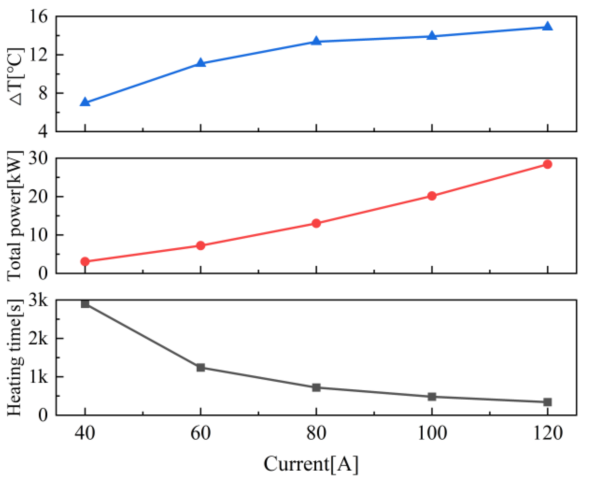
The effect of different AC current intensities on the temperature rise of the hot plate was studied at an AC frequency of 6 kHz and a constant distance of 15 mm between the coil and the hot plate. As the same as the experimental setup, the current values were taken as 40 A, 60 A, 80 A, 100 A, and 120 A in sequence. Continuous heating was conducted and the temperature distribution on the hot plate was recorded when the average temperature of coupled temperature field on the target surface reached 145 °C.
The curves of the temperature difference, total power, and heating time are shown in
Figure 8. It can be seen that as the current intensity increases, the temperature difference gradually increases, which indicates that at a lower current intensity, the temperature distribution is more uniform, while a higher current intensity leads to an obvious increase in temperature difference. The total power increases in a quadratic curve with the increase in current intensity, which are 3.076 kW, 7.219 kW, 13.021 kW, 20.154 kW, and 28.405 kW, respectively. Higher current intensity generates stronger electromagnetic field, thereby increasing Joule heating generation. The heating time significantly decreases with the increase in current, and the heating time of the hot plate is 2900 s, 1240 s, 720 s, 480 s, and 340 s, respectively, which indicates that a higher current intensity can significantly accelerate the heating rate, but it can also lead to an increase in temperature difference, affecting temperature uniformity. Due to the shorter heating time under a higher current intensity, the heat conduction time is relatively reduced, which is considered to be the reason for larger temperature difference.
To study this effect, the hot plate was heated to 145 °C and then kept warm until the next heating time point. The temperature difference data were recorded for comparative analysis, and the results are shown in
Figure 9. The experimental results indicate that the combination of heating time and holding time has a significant impact on temperature uniformity. Although the initial temperature difference is large, the rapid heating with higher current intensity and appropriate insulation time can lead to significant decrease in temperature difference, which is even better than the effect of long-term direct heating with lower current intensity. Therefore, in practical applications, higher current intensity and rapid heating combined with appropriate insulation time can be used to achieve better temperature uniformity.
4.2. AC Current Frequency
The effect of different AC current frequencies on the temperature rise of the hot plate was studied under the condition of constant AC current intensity of 60 A and a distance of 15 mm between the coil and the hot plate. In the experimental setup, the frequency values are taken as 3 kHz, 6 kHz, 10 kHz, 14 kHz, 18 kHz, and 22 kHz in sequence. Continuous heating was conducted, and the temperature distribution on the hot plate was recorded when the average temperature of the coupled temperature field on the target surface reached 145 °C.
The curves of temperature difference, total power, and heating time are shown in
Figure 10. It can be seen that as the current frequency increases, the temperature difference on the surface of the hot plate gradually increases, which indicates that under higher frequency, the heat distribution becomes uneven, leading to intensified temperature field fluctuations. The total power is positively correlated with current frequency, increasing from 3.412 kW at 3 kHz to 21.839 kW at 22 kHz as the frequency increases. Higher current frequencies generate stronger electromagnetic induction effects, leading to increased energy consumption and further expansion of temperature difference. Meanwhile, as the frequency increases, the heating time is significantly shortened. When the frequency increases from 3 kHz to 22 kHz, the heating time decreases from 2500 s to 430 s, indicating that higher current frequency significantly improves heating efficiency and can reach the target temperature in a shorter time. Therefore, in practical applications, it is necessary to balance heating efficiency and temperature uniformity and choose an appropriate current frequency to achieve the best heating effect.
4.3. Coil-to-Hot-Plate Distance
By adjusting the thickness of the heat-insulated plate, the distance between the electromagnetic heating coil and the hot plate can be changed. This change in distance directly affects the thickness of the air layer, causing changes in the electromagnetic field, eddy current field, and eddy current loss, ultimately affecting the uniformity of the temperature field [
3]. Under the condition of constant AC current intensity 60 A and AC frequency 3 kHz, the coil-to-hot-plate distance is set to 5 mm, 10 mm, 15 mm, 20 mm, and 25 mm, respectively. The temperature distribution on the hot plate was recorded when the average temperature of coupled temperature field on the target surface reached 145 °C.
The variations of the temperature difference, total power, and heating time of the hot plate with the coil-to-hot-plate distance are shown in
Figure 11. It can be seen that as the coil-to-hot-plate distance increases, the heating time gradually prolongs, indicating that a decrease in electromagnetic induction efficiency at larger distance results in a slower heating rate. Additionally, the temperature difference slightly decreases with increasing distance, reaching 8.28 °C at 5 mm and 7.15 °C at 25 mm. This indicates that the temperature distribution is more uniform at longer distance, which is considered due to the smoother distribution of electromagnetic fields on the hot plate. The total power gradually decreases with increasing distance, from 4.39 kW at 5 mm to 3.725 kW at 25 mm. The larger the distance, the weaker the electromagnetic coupling effect and the lower the power consumption. Although increasing the coil-to-hot-plate distance prolongs the heating time, it improves temperature uniformity and reduces power consumption. Therefore, increasing the distance appropriately can help optimize temperature distribution and improve energy efficiency, but a reasonable balance needs to be struck between heating time and temperature uniformity.
4.4. Design of Octagonal Plate Coil Pattern
According to the above simulation results, it still has a minimum temperature difference of 7.15 °C by using the coil in multi-ring pattern heating the octagonal hot plate. So, the coil pattern needs to be adjusted and optimized. The reason for the large temperature difference is that the four diagonal areas of the octagonal plate lack coil arrangement, resulting in less Joule heat generation and lower temperature in these areas. Referring to the arrangement of multi-ring coil, three types of coils were designed: the octagonal pattern, flower-shaped pattern, and inverted circular pattern, as shown in
Figure 12. The experimental conditions were set to a current intensity of 40 A, a current frequency of 6 kHz, and a coil-to-hot-plate distance of 15 mm. Magnetic–thermal coupling analysis was performed on these four coil patterns by using Maxwell software. The temperature distribution is shown in
Figure 13, and the temperature difference results of the hot plate are shown in
Figure 14.
As shown in
Figure 13a, the octagonal coil pattern has a relatively uniform temperature distribution on the hot plate, and the high-temperature and low-temperature areas are mainly concentrated at the edges, with an overall temperature difference of 4.48 °C and the temperature difference at the key temperature control ring area (see the dashed ring area in
Figure 13) of 3.74 °C. The performance of octagonal pattern is satisfactory. As shown in
Figure 13b, the flower-shaped coil pattern has a high-temperature distribution similar to that of an octagonal coil, with an overall temperature difference of 3.47 °C and a ring area temperature difference of 3.01 °C. The flower-shaped pattern has the best uniform heating effect. As shown in
Figure 13c, the circular coil pattern has the largest high-temperature area. Due to the lack of coil arrangement in the four corner areas, the temperature is relatively low, with an overall temperature difference of 7.33 °C and a ring area temperature difference of 5.22 °C. The heating uniformity of this pattern is the worst. As shown in
Figure 13d, the inverted circular coil pattern has a high temperature in the middle area, presenting a cross shape. The temperature difference of the entire plate is 5.21 °C, and the ring area temperature difference is 4.03 °C. The uniformity of the ring area is between that of an octagonal coil pattern and a circular coil pattern.
5. Conclusions
Experiment works were conducted on the hot plate by using an electromagnetic heating system, and the temperature uniformity was analyzed by measuring the temperature values of 24 measurement points. The results showed that the temperature difference of the hot plate was controlled within 3 °C, and the temperature remained stable without severe fluctuations during the continuous heating process for 6 h. These experimental results provide reliable experimental basis and technical guidance for the application of electromagnetic heating technology in solid tire vulcanization process.
Further simulation analysis shows that as the current and frequency increase, the heating rate significantly increases, but the temperature difference increases correspondingly. Increasing the coil-to-hot-plate distance will reduce the heating rate and slightly decrease the temperature difference. Using larger current intensity, higher current frequency heating combined with insulation treatment within the same heating time can achieve a more uniform temperature distribution than a lower current intensity, lower current frequency heating.
Simulation results also indicate that the temperature uniformity of the multi-ring coil pattern is optimal on a circular hot plate. In order to optimize the heating effect of the octagonal hot plate, three coil patterns, namely, octagonal, flower-shaped, and inverted circular patterns, were proposed based on the design of the multi-ring coil pattern. Simulation analysis shows that the flower-shaped coil pattern performs best in controlling both the temperature difference of the entire hot plate and the temperature difference of the intermediate ring area. Meanwhile, the conventional circular coil pattern has significant temperature difference and worst uniformity. This indicates that the flower-shaped coil pattern is more suitable for the uniform heating requirements of octagonal hot plates and provides effective reference for the design of coils for specific-shaped hot plate.
6. Future Research Directions
Machine learning for heating parameter optimization: integrating machine learning algorithms (e.g., reinforcement learning or genetic algorithms) could dynamically explore optimal parameter combinations for the electromagnetic heating system, further improving temperature uniformity and energy efficiency.
Magnetic shielding technology for thermal management: deploying magnetic shielding materials (e.g., ferrites) in localized overheating zones may regulate magnetic field distribution and mitigate hot plate formation. This could be combined with sensor placement optimization to refine system design.
Author Contributions
Conceptualization, J.G. and H.X.; methodology, Z.X. and M.C.; software, Z.X.; validation, Z.X., H.X. and M.C.; formal analysis, Z.X. and J.G.; investigation, J.G. and H.X.; resources, J.G. and H.X.; data curation, Z.X.; writing—original draft preparation, Z.X. and J.G.; writing—review and editing, H.X. and M.C.; visualization, J.G.; supervision, R.T.; project administration, H.X., M.C. and R.T.; funding acquisition, H.X., M.C. and R.T. All authors have read and agreed to the published version of the manuscript.
Funding
This research was funded by Guangxi Key R&D Program, grant number Gui Ke AB24010262; and Guangxi Key Laboratory of Manufacturing Systems and Advanced Manufacturing Technology Director’s Fund Project, grant number 22-35-4-S020.
Data Availability Statement
The original contributions presented in the study are included in the article; further inquiries can be directed to the corresponding author.
Acknowledgments
The authors would like to thank all those who provided valuable comments and suggestions to improve the quality of this study.
Conflicts of Interest
H.X was employed by the company Guilin Rubber Machinery Co., Ltd. The remaining authors declare that the research was conducted in the absence of any commercial or financial relationships that could be construed as a potential conflict of interest.
References
- Zhang, Z.; Jia, X.; Guo, F.; Huang, X.; Wang, Y. Numerical Analysis of Heat Transfer and Chemical Reaction Coupling in the Rubber Seal Vulcanization Process. Rubber Chem. Technol. 2022, 95, 342–358. [Google Scholar] [CrossRef]
- Yang, W.; Sun, Y.; Shao, Z.; An, Y.; Jiao, Z.; Tan, J. Temperature field simulation of tire drum tires heated by electromagnetic induction. J. Beijing Univ. Chem. Technol. (Nat. Sci. Ed.) 2023, 50, 50–58. [Google Scholar]
- Wang, H. Simulation and Experimental Study of Electromagnetic Vulcanization of Rubber; Qingdao University of Science and Technology: Qingdao, China, 2020. [Google Scholar]
- Yu, L.; Chen, X.; Yang, Q. Numerical simulation study on electromagnetic heating of hot plate in flat vulcanizing machine. Mach. Manuf. 2018, 56, 13–17. [Google Scholar]
- Li, K.; Li, J.; Lu, L.; Gao, L. Temperature monitoring of conveyor belt joint vulcanization induction heating system based on type K thermocouple. Instrum. Technol. Sens. 2020, 8, 70–76. [Google Scholar]
- Zhai, Z.; He, J.; An, Y.; Tan, J. Program design of electromagnetic heating vulcanization hot plate. Mech. Des. Manuf. 2019, 5, 5–9. [Google Scholar]
- Wang, J.; Chen, X.; Yu, L.; Sun, B.; Li, D. A Novel Method Improving the Temperature Uniformity of Hot-Plate Under Induction Heating. Proc. Inst. Mech. Eng. Part C J. Mech. Eng. Sci. 2021, 235, 190–201. [Google Scholar]
- Wang, Y.; Li, S.; He, Z. Influence Law of Electromagnetic Induction Heating Parameters on the Leveling Effect in Thin Plates. J. Phys. Conf. Ser. 2024, 2785, 012101. [Google Scholar] [CrossRef]
- Wang, J. Optimization of Hot Plate Temperature in Vulcanizing Machine Based on Electromagnetic Heating; Ningbo University: Ningbo, China, 2021. [Google Scholar]
- Dong, J.; Luo, Y.; Jiang, W.; Gu, W.; Dong, P. Control of homogeneity and optimization of parameters for induction heating of large thick-walled cylinders. Met. Heat Treat. 2024, 49, 275–279. [Google Scholar]
- Lu, M.; Li, J.; Zhang, H.; Song, J. Study on the temperature field of hot plate of tape vulcanizer based on orthogonal test. Coal Eng. 2021, 53, 152–157. [Google Scholar]
- Zhou, J. Simulation and Optimization of Electromagnetic Heating Hot Plate for Tire Curing Machine; Shandong University: Jinan, China, 2022. [Google Scholar]
- Sun, G. Finite Element Simulation and Experiment on Electromagnetic Heating of Hot Plate of Vulcanizing Machine. Ningbo University: Ningbo, China, 2022. [Google Scholar]
- Zhang, A.; Zuo, Y.; Zhang, M.; Zhou, H. Numerical Study on Thermal Performance and Thermal Stress of Molten Salt Receiver Tube Based on Induction Heating. Appl. Therm. Eng. 2023, 235, 121353. [Google Scholar] [CrossRef]
- Talal, A.; Salem, A.; Faouzi, A. Numerical Investigation on Performance Enhancement of Metal-hydride Hydrogen Tank Using Electromagnetic Induction Heating. Appl. Therm. Eng. 2023, 224, 120072. [Google Scholar]
- Fan, N. Research on Electromagnetic Heating Device for Inner and Outer Molds of Tire Curing Machine; Shandong University: Jinan, China, 2023. [Google Scholar]
- Pan, X. Research on Temperature Field Uniformity of Electromagnetic Vulcanizing Device; Qingdao University of Science and Technology: Qingdao, China, 2020. [Google Scholar]
- Zhang, Z.; Zhang, G.; Yu, X.; Li, X. Simulation analysis of magnetic field distribution of electromagnetic hot plate in tire curing machine. Rubber Plast. Technol. Equip. 2020, 46, 45–50. [Google Scholar]
- Mayur, P.; Rahul, K.; Prashant, K. Influence of Coil Shapes on Temperature Distribution in Induction Heating Process. Mater. Today Proc. 2023, 72, 3029–3035. [Google Scholar]
| Disclaimer/Publisher’s Note: The statements, opinions and data contained in all publications are solely those of the individual author(s) and contributor(s) and not of MDPI and/or the editor(s). MDPI and/or the editor(s) disclaim responsibility for any injury to people or property resulting from any ideas, methods, instructions or products referred to in the content. |
© 2025 by the authors. Licensee MDPI, Basel, Switzerland. This article is an open access article distributed under the terms and conditions of the Creative Commons Attribution (CC BY) license (https://creativecommons.org/licenses/by/4.0/).


