Article

Integration of a Double-Concentrated Solar Cooking System Operable from Inside a Home for Energy Sustainability

by
Raul Asher García Uribe
1,2,
Sergio Rodríguez Miranda
1,
Lourdes Vital López
3,
Marco Antonio Zamora Antuñano
4,5 and
Raúl García García
1,*
1
Division of Chemistry and Renewable Energy, Universidad Tecnológica de San Juan del Rio (UTSJR), San Juan del Río Querétaro 76900, Mexico
2
Posgraduate Departament, Universidad Centro Panamericano de Estudios Superiores, Zitácuaro Michoacán 61506, Mexico
3
Carrera de Mantenimiento Industrial, Universidad Tecnológica de Tamaulipas Norte, Reynosa Tamaulipas 88680, Mexico
4
Council of Science and Technology of the State of Querétaro (CONCYTEQ), Av. Prol. Luis Pasteur 36, Centro, Santiago de Querétaro 76000, Mexico
5
Posgraduate Departament, University of Research and Innovation of Mexico (UIIX), Cuernavaca 62290, Mexico
*
Author to whom correspondence should be addressed.
Energies 2025, 18(11), 2673; https://doi.org/10.3390/en18112673
Submission received: 29 March 2025 / Revised: 27 April 2025 / Accepted: 19 May 2025 / Published: 22 May 2025
(This article belongs to the Section A2: Solar Energy and Photovoltaic Systems)

Abstract

:
Cooking food is a factor that contributes to global energy consumption and greenhouse gas emissions. This research proposes the design, simulation using thermal resistances with MATLAB Simulink, and experimental evaluation of an automated double-concentrated solar cooking system operable from inside a home. Water was used as a cooking load. Each test for 25 min was entered into a system integrated by a programmable elevator to transport the food to the roof, a configurable temperature display, a photovoltaic power source, and double solar collection (direct through a modified box oven and reflected by a parabolic dish collector). When both solar components operated simultaneously, the system reached a temperature of 79 °C, representing a 57.34 °C increase. On average, the solar concentrator provided 78.02% more energy than the oven alone. This approach is expected to reduce cooking time and contribute to sustainable home design aimed at mitigating greenhouse gas emissions.

1. Introduction

The energy crisis has become one of the most serious problems threatening human survival and limiting social development [1]. In this context, solar technology is presented as a viable and environmentally safe alternative, capable of enduring for billions of years [2].
The use of solar energy has grown significantly in various sectors such as homes, industry, agriculture, transportation, water purification [3,4], space air conditioning [5], building heating [6], facade and wall design [7], rural electrification [8], and power generation based on the efficiency of solar cells and modules [9]. This growth has been driven by the development of advanced technologies, especially in the field of solar cells, where organic–inorganic lead halide perovskite materials stand out [10], the use of TiO2 nanoparticle bilayers [11,12], the improvement in broadband light absorption and light harvesting [13], as well as the study of optoelectronic properties [14], all of which are aimed at the manufacture of high-efficiency solar cells [15].
In addition to its application in electricity generation, solar energy is also used in everyday activities such as cooking, which represents a significant portion of energy consumption in developing countries [16].
The increase in electricity generation from renewable sources has led to a more sophisticated understanding of end-user energy demand profiles [17,18]. Together, these advances position solar energy as one of the most promising solutions to current and future energy challenges.
Solar energy contributes significantly to meeting global energy needs, especially in developing countries. Cooking, which accounts for approximately 30% to 40% of global energy consumption particularly in developing and underdeveloped regions, is one of the major contributors to energy use and greenhouse gas emissions [19].
Solar cookers, which require no fuel and have minimal operating costs, represent a promising solution within the decentralized energy sector [20]. They are generally classified by heat transfer method (direct or indirect) [21], and their designs include box, parabolic, panel, and vacuum tube types [22]. Among these, solar concentration cookers (CSCs) stand out for their ability to achieve high temperatures and reduce cooking time, making them suitable for large scale kitchens [23]. Innovations such as incorporating heat storing materials into box-style cookers have been developed to improve performance [24].
The use of a single solar cooker per two-person household can reduce carbon dioxide emissions by approximately 148.3 kg per year [24]. Ongoing research aims to improve the efficiency and productivity of these systems through experimental, energy, and economic analyses [23,25]. Advanced models, like the stepped solar box furnace (SSBC) using SiO2/TiO2 nanoparticles [26] and evacuated tubes [27], have been studied for their thermal and optical properties in relation to solar radiation. Solar thermal energy, as a renewable and abundant source, is a competitive option for meeting global thermal energy needs [28].
Different types of solar concentrators have been explored, such as the parabolic dish system, with research focusing on optimizing parameters like focal length and radiation concentration [29,30,31]. Despite the availability of various models [32], many solar cookers are designed exclusively for outdoor use and lack user centric features, which limits their acceptance.
Social and behavioral barriers continue to hinder widespread adoption. El-Khozenadar et al. (2022) found low social acceptance of solar cooking appliances in the Gaza Strip, attributing it to limited awareness, financial constraints, and educational factors [33]. Only 37.7% of participants supported the use of solar energy for cooking, while 94.55% viewed it as more appropriate for lighting. The study also concluded that gender and employment status do not significantly affect acceptance.
To address these challenges, Lecuona-Neumann et al. (2024) proposed innovative solar cooking devices such as a frying pan or generic heater powered by photovoltaic panels connected to PTC resistors [34]. Designed for family use, these devices can be easily scaled for greater power while maintaining simplicity.
In New York City, Lane et al. (2024) assessed perceptions of clean-energy cooking technologies [35]. They found that 71% of gas stove users were uninterested in switching, with 45% preferring gas for cooking. Although 77% expressed interest in solar energy, only 5% actually used it. Key barriers included confusion about operation, costs, and lack of control over energy decisions. The authors recommend targeted education and subsidies to promote adoption and suggest regular tracking of clean energy adoption metrics to ensure equity.
Kumar et al. (2024) conducted a financial assessment of a Scheffler dish solar cooker in Rajasthan, India [36]. Each unit cooked 1424 meals per year and saved an estimated 679 kg of LPG annually. These systems also contributed to improving women’s health, reducing child mortality, and lowering CO2 emissions.
This research proposes the design, simulation, and experimental evaluation of an automated double-concentrated solar cooking system, operable from inside a home. The system incorporates an automated elevator, a configurable temperature display, a photovoltaic power source, and double solar collection (direct and reflected). Its objective is to improve user comfort, achieve cooking temperatures in less time, and integrate the use of solar cookers into residential architecture, thus contributing to the mitigation of greenhouse gas emissions.

2. Materials and Methods

Before building the system, the design’s feasibility to predict system temperatures was assessed. The Weather Underground tool, a website that lists most weather stations, was used. Irradiance and ambient temperature data for each day of the experiment were obtained from the CEA-JAPAM IQUERETA13 weather station. As a first approximation, a simulation was performed using MATLAB Simulink 2018 (Natick, MA, USA, EE. UU), considering energy input and output, mass, and temperature variation.
The system is powered by an Elite Solar brand monocrystalline photovoltaic module, model ET-M772BH550WW, manufactured in Hong Kong, China and uses a parabolic dish collector (PDC) that supplies power to the rear of a modified box oven, optimized to capture more radiation than a conventional design. For ease of use from inside a home, it features a programmable elevator that transports food to the roof, where cooking takes place. The integrated visual display allows monitoring of times and temperatures throughout the process (Figure 1).

2.1. Simulation and Heat Balance

Thermal balance makes it possible to determine the temperature and heat flow in system elements by analyzing the sum of energy inputs and outputs, governed by heat transfer mechanisms. When a temperature gradient exists, heat is transferred through conduction, convection, or radiation key processes in the thermal analysis of thermosolar devices.
In dynamic (time-based) analysis, it is essential to track temperature changes in each element, which depend on the material’s heat capacity, mass, and energy input properties that define its thermal inertia.
The simulation was carried out in MATLAB Simulink 2018, which uses a block programming structure with thermal resistance libraries. Each block, represented by geometric shapes, processes signals (data flows) indicated by directional arrows.
Figure 2 illustrates the complete simulation model, consisting of three main parts: energy input, energy output, and the thermal mass. Energy enters the oven through the front and rear glass panes and is lost via walls, glass panes, and the bottom. The resulting energy balance determines the oven temperature over time.
Figure 2 shows the block diagram for this phenomenon, using the electrical circuit analogy. This is a useful technique to simplify the analysis and visualization of the thermal balance by performing an analogy with an electric circuit, taking the temperature difference as an electric potential difference and the thermal inertia as a capacitance and a heat source as a current source.
The energy input comes from the solar radiation incident directly on the solar oven and is reflected by the PDC (blue block). This block is a subsystem formed by basic blocks. Figure 3 shows the arrangement of these blocks and the signal flow that will represent the incident solar radiation. A basic signal (red block) generates a normalized curve with values from 0 to 1 over a 24 h period, representing the way in which solar radiation increases and decreases during the day. The signal with these values advances to the left to change until it best represents the incident energy for cooking.
At the upper fork of the signal, the first triangular block is multiplied by 900 W/m2, which will be the maximum value of solar radiation. The second triangle represents the glass’s transmittance of 88%, therefore this block is a multiplication by 0.88. The third block was left for future corrections in this case without modification to the signal; it is up to the fourth block that it is multiplied by the value of the collection area in m2 (Section 2.2); in this way, the radiation is now presented in W. The circular block is an addition operation between the previously described representation of the energy captured directly by the oven (upper fork) and the energy captured by the concentrator (lower fork), which has the same structure.
The total energy is stored by the thermal mass block, which is included in the MATLAB Simulink library for modeling thermal systems. These blocks are subsystems created by basic blocks and only the required properties of the associated material, in this case water, need to be indicated. The energy losses flow through the oven to the environment; this is represented by the thermal resistances that are grouped into three subgroups shown on the left side of Figure 2: resistance in the walls (red block), resistance in the glass (green block), and resistance in the lower part (purple block).
The breakdown of the wall resistances is presented in Figure 4, which consists of a series and parallel arrangement of individual resistances, representative of the energy flow by conductivity in a pine wood layer (thermal conductivity 0.046 W/(m °C)), continuing by conductivity in silica sand (thermal conductivity 1 W/(m °C)), again passing through a pine wood layer, and finally by convection (heat transfer coefficient 10 W/(m2 °C)) and radiation (radiation coefficient 4 × 10⁻⁸ W/(m2 °K4)) to the environment. The composition of the material, its thickness, and the exposed area are as indicated in Section 2.2. These values are loaded into the program, and it automatically determines the resistance value and, the breakdown for the resistances in the glass, conductivity through the glass (thermal conductivity 0.7 W/(m °C)), convection (heat transfer coefficient 10 W/(m2 °C)), and radiation (radiation coefficient 4 × 10⁻⁸ W/(m2 °K 4)) with the environment. Finally, the resistance at the bottom, conduction through the pine wood, convection (heat transfer coefficient 10 W/(m2 °C)), and radiation (radiation coefficient 4 × 10⁻⁸ W/(m2 °K 4)) with the environment are calculated.
pine wood layer thermal conductivity 0.046 W/(m °C)
silica sand (thermal conductivity 1 W/(m °C)
convection (heat transfer coefficient 10 W/(m2 °C))
radiation (radiation coefficient 4 × 10⁻⁸ W/ (m2 °K 4)
glass (thermal conductivity 0.7 W/(m °C)),

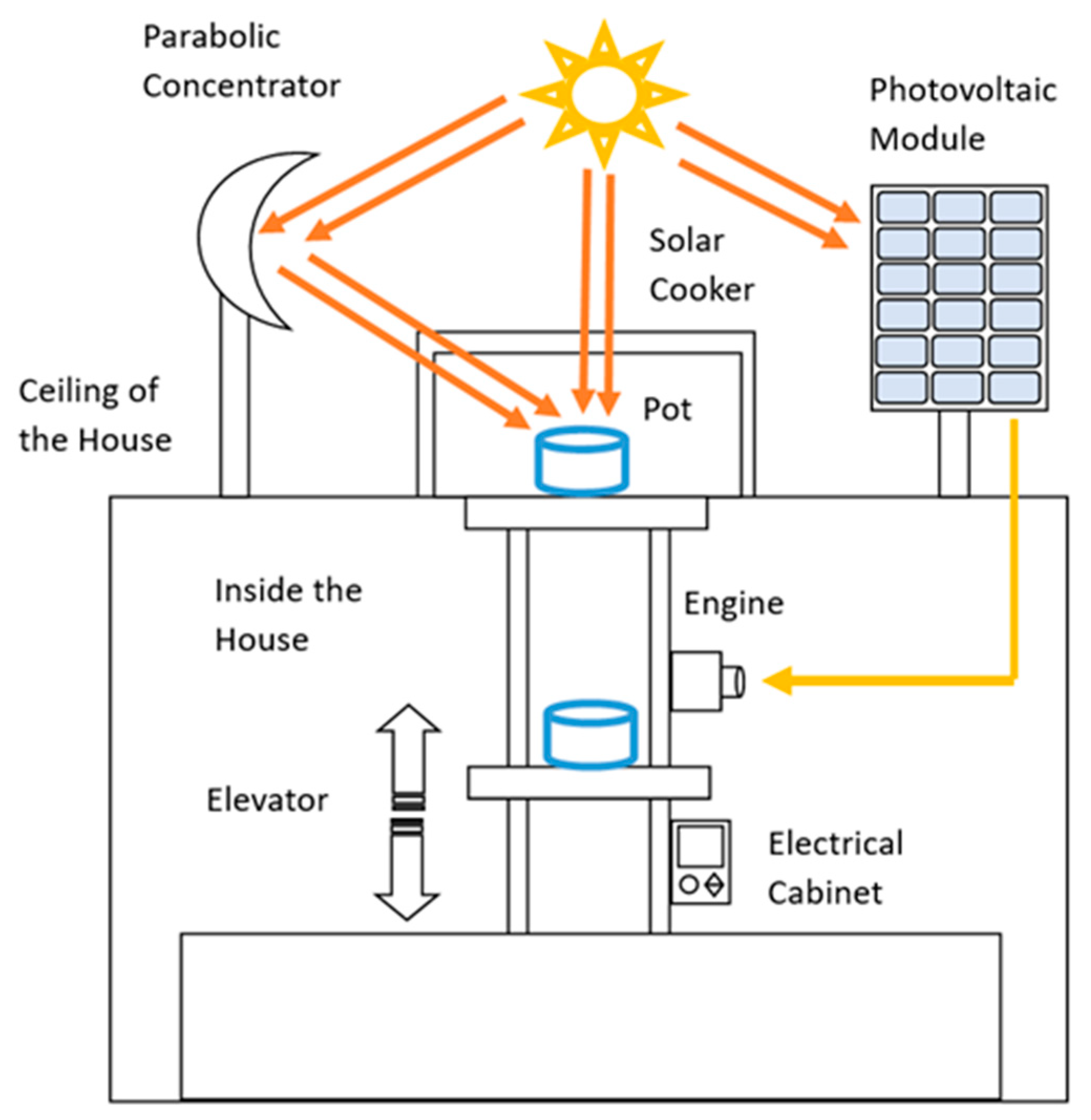
2.2. Systems Integration

2.2.1. Furnace Design

The solar oven is installed on the roof facing south, with its front inclined according to the local latitude, as shown in Figure 5.

2.2.2. Design of the Parabolic Dish Collector

The PDC (Figure 7) is constructed from 3 mm thick aluminum because of its high reflectivity, which helps concentrate solar radiation directed toward the rear of the modified box furnace. The focal length, calculated as f = r2/(4 × h), is 500 mm, based on a radius (r) of 750 mm and a depth (h) of 281 mm.

2.2.3. System Programming and Automation

Figure 8 shows the main components of the system. It allows food to be transported comfortably in the oven since the elevation is automated when moving from the inside of the house to the ceiling.
For programming (see Section 3.3) of the digital inputs and outputs of the integrated solar cooker, an Allen Bradley PLC, Model Q1B1, and an Allen-Bradley module, Model 1734-IT2I, are used. The temperature signals from a Prense thermocouple, Model J type, are observed on an Allen-Bradley PanelView, Model Plus 700. All the devices mentioned are manufactured by Rockwell Automation, a company based in Milwaukee, WI, USA.
Electricity is generated by a photovoltaic panel that powers automated equipment [37,38]. In this study, the electrical system consists of a 550-Watt monocrystalline module that supplies power to a FTVOGUE charge controller, model BSC3048, with nominal voltages of 12/24/36/48 V. This controller powers the components installed inside an IUSA brand cabinet, with IP65 protection and dimensions of 35 cm × 35 cm × 18 cm. Inside the cabinet, digital signals are received from the elevator’s lower (initial position) and upper (final position) limit sensors, in addition to the thermocouple analog inputs, the connections to the PanelView display panel, the programmable logic controller (PLC), and the operation buttons (start, stop, and general stop), as detailed in Section 3.3.

3. Results and Discussion

This section presents and discusses the results obtained from the simulations in the software MATLAB Simulink. First, the direct solar radiation incident on the front part of the furnace, the simulation of the box furnace receiving direct and reflected radiation, and the experimental determination of the prototype were performed. Cooking times and temperatures were programmed, and the system for transporting the food to the roof was automated.

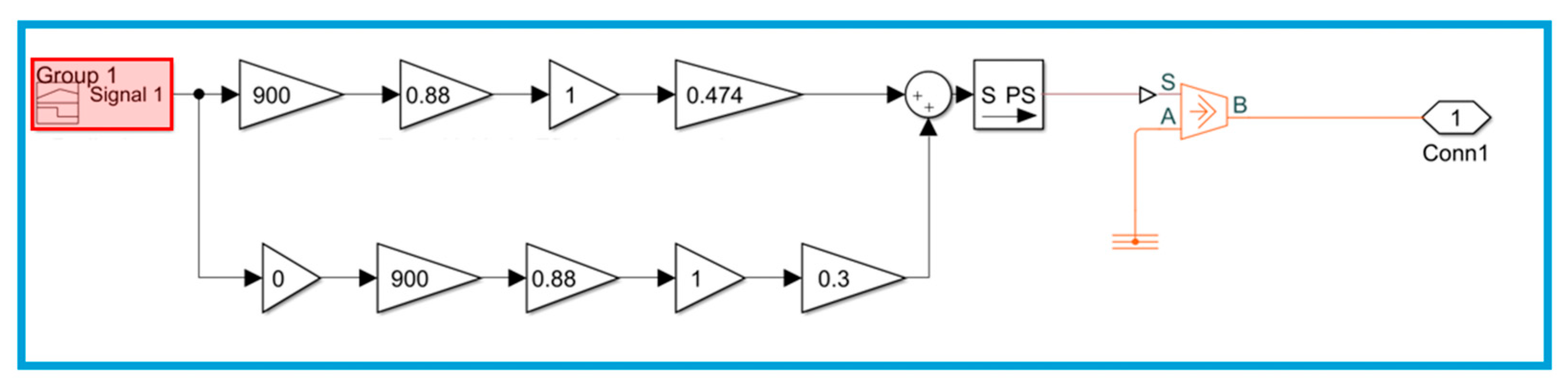
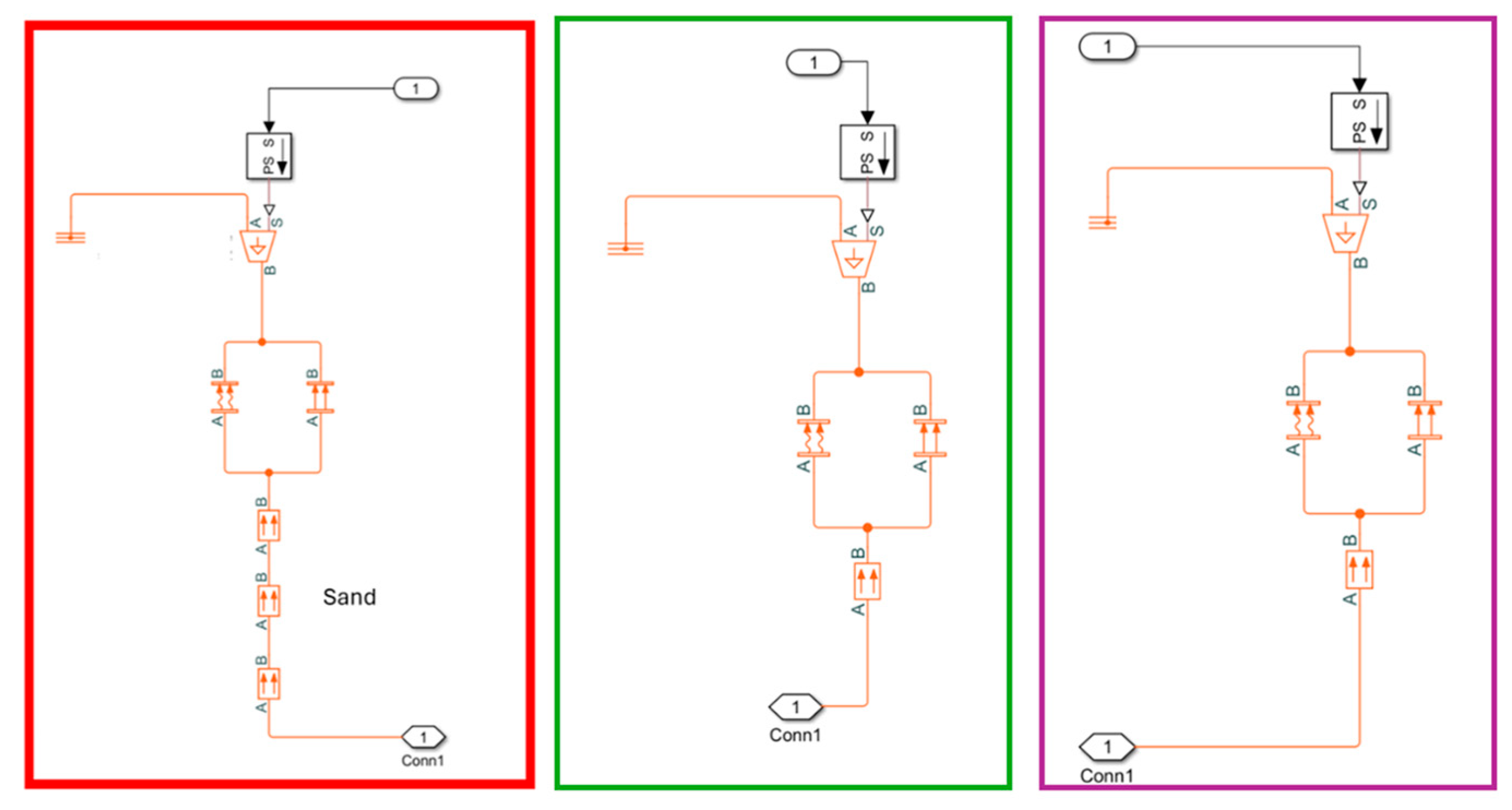
3.1. Simulation with MATLAB

Considering the ambient temperature of a typical summer day (T) as well as the amount of incident solar energy and irradiance in W/m2, the data are simulated to obtain the temperatures reached in the oven directly (T) and the temperatures under the influence of the solar concentrator (Tc) in 1000 mL of water contained in an aluminum container.
Figure 9 shows the temperatures reached in the simulation for solar furnaces directly (T) and with the concentrator (Tc), and the maximum increase in the oven temperature with concentration (Tc) is 57.64 °C with respect to the ambient temperature (Ta) and 35.99 °C when only the solar oven is used (T). These results are preliminary as they are only a representation of the phenomenon.
Summarizing the simulation over time considers the level of solar radiation as input and ambient temperature approximate to the experimental data for a later comparison (variables in time as shown in Figure 9). The volume of water to heat was 1000 mL. The thermal conductivity of the pine wood materials was considered to be 0.046 W/(m °C), for silica sand it was 1 W/(m °C), and for glass, 0.7 W/(m °C). A global coefficient of heat transfer by convection 10 W/(m2 °C) and global coefficient of radiation 4 × 10⁻⁸ W/(m2 K4) were considered.
Simulations have been carried out on solar thermal cooking devices for domestic cooking applications which differ completely from the one presented in this study, since they depend on the flow of heat transfer fluid [39].

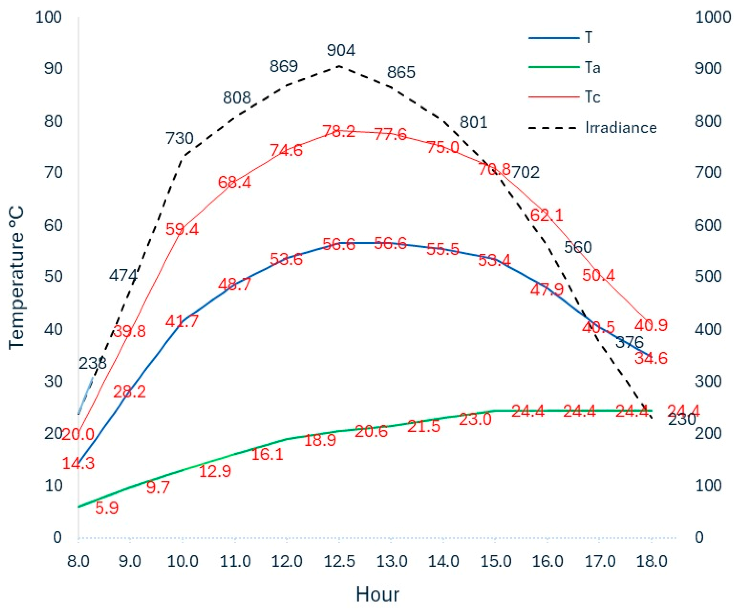
3.2. Thermal Evaluation of the Furnace and PDC

Figure 10 shows the thermal evaluation of the system performed on a typical autumn day. Twenty-two samples were analyzed, each exposed for 25 min between 8:00 a.m. and 6:00 p.m., starting the experiment at room temperature (Ta). Eleven of them were placed in a conventional oven and subjected to direct solar radiation (T), while the remaining were in a modified box oven, which received solar energy both directly through the front glass and reflected by the parabolic concentrator through the rear glass (Tc). During the exposure period, the temperature of each sample was recorded. Ambient temperature and solar irradiance data came from the CEA-JAPAM IQUERETA13 meteorological station.
The water temperature increased in 25 min, starting from an ambient temperature of 21.66 °C at 1:00 p.m., then 36.34 °C, and ultimately reaching 58 °C using only the oven. Operating the solar concentrator and oven simultaneously, the temperature reached was 79 °C, 57.34 °C higher than the initial temperature (see Figure 10).
There are several comparisons of solar cookers using conventional parabolic solar concentrators to heat water as the cooking load. Kateglo et al. [32] obtained temperatures between 90 °C and 99 °C in 50 min. Wollele et al. [40] reached a maximum water temperature of 81.85 °C in 15 min more than in this study. This latter temperature value is similar to the one found in this study. Recent studies evaluated the thermal behavior of solar cookers by heating water, such as that of Xabier Apaolaza et al. [22] which takes 114 min to boil 1.5 kg of water, or that of Aquilanti et al. [23] which uses ambient conditions and the same amount of water (1 kg). The average heating times for the water to reach boiling point were 1.74 and 1.66 h, respectively, reaching a temperature gradient of 50 °C. The model presented in this study reaches a slightly higher temperature (57.34 °C) gradient in less time (approximately one hour).
Comparing the temperature results of the simulation with the experimental data reveals a small variation during the periods of maximum radiation, which would be from 11:00 a.m. to 4:00 p.m. Figure 11 shows the temperature difference in the solar cooker, concentrating on the simulation and the experimentally obtained data.
On average, the solar concentrator contributed 78.02% of the temperature reached by each sample.

3.3. System Programming and Automation

Figure 12 shows the interconnection diagram between the equipment accessories, located inside an electrical cabinet where digital signals arrive from the sensors and analog inputs of the thermocouple, connections of the PanelView, PLC, and buttons (start, stop, general stop).
Figure 13 shows the programming diagram of the food cooking process, operating from the interior to the rooftop of a home, and the PanelView.
In Row 0 of the ladder diagram, the analog data from the thermocouple are acquired through the data acquisition card Model 1734-IT2I. An internal variable is created in the DINT program with the name VALUE_DATOS_TERMOPAR to visualize the data acquired from the thermocouple, which are divided with the DIV instruction. The value is saved in an internal variable of the program with the name, VALUE_TEMPERATURA. This value represents the temperature in which the system is located and is the visual reference of the user on the Human Machine Interface (HMI) screen.
In line 1, two physical inputs are programmed and declared in the program as follows: STOP and EMERGENCY-STOP activate an internal coil called SAFETY in the ladder diagram.
Line 2 sends an ALARM when the STOP_GENERAL button or SECURITY signal is activated to the PanelView (HMI), indicating that the security is not correct.
Lines 3 and 4 of the ladder diagram contain the internal variables declared AUT_PANT AND MAN_PANT to activate the elevator work mode by activating an internal PLC coil AUT AND MAN.
In lines 5 and 6, there is the activation of a lantch (PLC instruction) with a physical input called LIM_SUP (I: 0/4 of the PLC).
For the unlocking of this variable, a latch (PLC instruction) activated by LIM_INF (I: 0/3 of the PLC) is used, repeating the logic of this sequence for lines 7 and 8.
In line 9, we have the manual or automatic work mode. By selecting the AUT or MAN work mode in the ladder diagram, all the variables assigned in the row must be in green to fulfill this sequence. The physical button is pressed so that the lift will be lowered by the action of the motor, which is assigned as MOTOR_LOW.
T1. EN: the timer that automatically lowers the system when it reaches the cooking time given by the operator.
Line 9 is similar to Line 10 except that it changes the name of the variables and raises the mechanism to the cooking zone.
In lines 11 and 12, there is a timer that is activated when AUTOMATIC mode is selected in the HMI. This works when the elevator reaches the upper position and the LIM_SUP sensor (I: 0/4 of the PLC) activates it to start counting according to the given programming. When the equality is fulfilled, it is activated in Row 9 of the ladder diagram so that it automatically decreases; this timer is reset in Row 12 by T1. DN AND LIM_INF so that it resets the timer to 0.
The average energy measured in our area per m2 is 5.1416 kWh/m2. Compared to European countries, the radiation at our location is high. In Spain, the average annual radiation is 4.40 kWh/m2/day, making it the sunniest country in Europe. Therefore, generating electricity with a 550-watt monocrystalline photovoltaic panel is feasible to power the proposed cooking process [41,42].

4. Conclusions

According to National survey on energy consumption (ENCEVI) 2018, in Mexico, cooking food represents 77% of the thermal energy in homes, of which up to 80% is provided by liquefied petroleum gas, which highlights the need to study new cooking options that are friendly to the environment.
This work shows the possibility of integrating technology with clean energy generation systems to comfortably operate a solar cooker located inside a house for cooking food. The design avoids the exposure of people to sunlight. The simulation allowed us to obtain an approximation of the real results obtained, with greater correlation in the hours of solar radiation; this suggests considering the optical effects of reflection and refraction on the surfaces. However, it is useful to test future variations in the design prior to its construction. The temperature reached by the system depends on the solar radiation of the place during the year. Therefore, higher temperatures than those presented in this research can be obtained; for this purpose, it is necessary to avoid forming a shadow between the PDC and the modified box furnace. As a continuation of this work, it is expected that this type of system will be part of the sustainable architecture of the houses. One of the main challenges remains to use this type of system at any time during the 24 h of the day with the same efficiency, in addition to the incorporation of materials and devices that when integrated into solar cookers are economically competitive with the costs of stoves that use LP gas. This is important for the scalability of the technology and its adaptability to different geographic and climatic conditions, and the possible extension of the system to other fields, such as the degradation of medicines by heat, which will be the subject of study in future research.

Author Contributions

Conceptualization, R.A.G.U., S.R.M. and R.G.G.; Methodology, R.G.G., M.A.Z.A., L.V.L., R.A.G.U. and S.R.M.; Writing—original draft preparation, S.R.M., R.G.G., L.V.L., and M.A.Z.A.; Writing—review and editing, R.G.G., M.A.Z.A. and S.R.M.; Supervision, R.G.G., S.R.M. and L.V.L. All authors have read and agreed to the published version of the manuscript.

Funding

This research received no external funding.

Data Availability Statement

The original contributions presented in this study are included in the article. Further inquiries can be directed to the corresponding author.

Acknowledgments

This work was performed under the support of the project CONCYTEQ/CACTI/102/2024.

Conflicts of Interest

The authors declare no conflicts of interest.

References

  1. Hao, L.; Liu, N.; Niu, R.; Gong, J.; Tang, T. High-performance salt-resistant solar interfacial evaporation by flexible robust porous carbon/pulp fiber membrane. Sci. China Mater. 2022, 65, 201–212. [Google Scholar] [CrossRef]
  2. Obaideen, K.; Olabi, A.G.; Al Swailmeen, Y.; Shehata, N.; Abdelkareem, M.A.; Alami, A.H.; Rodriguez, C.; Sayed, E.T. Solar Energy: Applications, Trends Analysis, Bibliometric Analysis and Research Contribution to Sustainable Development Goals (SDGs). Sustainability 2023, 15, 1418. [Google Scholar] [CrossRef]
  3. Arunkumar, T.; Sathyamurthy, R.; Denkenberger, D.; Lee, S.J. Solar distillation meets the real world: A review of solar stills purifying real wastewater and seawater. Environ. Sci. Pollut. Res. 2022, 29, 22860–22884. [Google Scholar] [CrossRef]
  4. Han, J.; Dong, Z.; Hao, L.; Gong, J.; Zhao, Q. Poly(ionic liquid)-crosslinked graphene oxide/carbon nanotube membranes as efficient solar steam generators. Green Energy Environ. 2021, 8, 151–162. [Google Scholar] [CrossRef]
  5. Rodriguez Miranda, S.; Gamboa, G.O.; Zamora-Antuñano, M.A.; Farrera-Vázquez, N.; García-García, R. CFD Evaluation of Thermal Conditioning in a House of Social Interest with a Solar Chimney Arrangement in Guanajuato, Mexico. Processes 2023, 11, 1286. [Google Scholar] [CrossRef]
  6. Liu, Y.; Yu, Z.; Song, C.; Wang, D. Heating load reduction characteristics of passive solar buildings in Tibet, China. Build. Simul. 2021, 15, 975–994. [Google Scholar] [CrossRef]
  7. Alghoul, S.K.; Rijabo, H.G.; Mashena, M.E. Energy consumption in buildings: A correlation for the influence of window to wall ratio and window orientation in Tripoli, Libya. J. Build. Eng. 2017, 11, 82–86. [Google Scholar] [CrossRef]
  8. Tiwari, P.; Manas, M.; Jan, P.; Nemec, Z.; Radovan, D.; Mahanta, P. A Review on Microgrid Based on Hybrid Renewable Energy Sources in South-Asian Perspective. Technol. Econ. Smart Grids Sustain. Energy 2017, 2, 10. [Google Scholar] [CrossRef]
  9. Green, M.A.; Dunlop, E.D.; Hohl-Ebinger, J.; Yoshita, M.; Kopidakis, N.; Hao, X. Solar cell efficiency tables (version 56). Prog. Photovolt. Res. Appl. 2020, 28, 629–638. [Google Scholar] [CrossRef]
  10. Jena, A.K.; Kulkarni, A.; Miyasaka, T. Halide perovskite photovoltaics: Background, status, and future prospects. Chem. Rev. 2019, 119, 3036–3103. [Google Scholar] [CrossRef]
  11. Shahiduzzaman, M.; Hossain, M.I.; Otani, S.; Wang, L.; Umezu, S.; Kaneko, T.; Iwamori, S.; Tomita, K.; Tsang, Y.H.; Akhtaruzzaman, M.; et al. Low-temperature treated anatase TiO2 nanophotonic-structured contact design for efficient triple-cation perovskite solar cells. Chem. Eng. J. 2021, 426, 131831. [Google Scholar] [CrossRef]
  12. Hossain, M.I.; Shahiduzzaman, M.; Ahmed, S.; Huqe, M.R.; Qarony, W.; Saleque, A.M.; Akhtaruzzaman, M.; Knipp, D.; Tsang, Y.H.; Taima, T.; et al. Near field control for enhanced photovoltaic performance and photostability in perovskite solar cells. Nano Energy 2021, 89, 106388. [Google Scholar] [CrossRef]
  13. Akhtaruzzaman, M.; Hossain, M.I.; Islam, M.A.; Shahiduzzaman, M.; Muhammad, G.; Hasan, A.K.M.; Tsang, Y.H. Nanophotonic-structured front contact for high-performance perovskite solar cells. Sci. China Mater. 2022, 65, 1727–1740. [Google Scholar] [CrossRef]
  14. Kim, J.Y.; Lee, J.-W.; Jung, H.S.; Shin, H.; Park, N.-G. High-efficiency perovskite solar cells. Chem. Rev. 2020, 120, 7867–7918. [Google Scholar] [CrossRef] [PubMed]
  15. Hossain, M.I.; Saleque, A.M.; Ahmed, S.; Saidjafarzoda, I.; Shahiduzzaman, M.; Qarony, W.; Knipp, D.; Biyikli, N.; Tsang, Y.H. Perovskite/perovskite planar tandem solar cells: A comprehensive guideline for reaching energy conversion efficiency beyond 30%. Nano Energy 2021, 79, 105400. [Google Scholar] [CrossRef]
  16. Panwar, N.L.; Kaushik, S.C.; Kothari, S. State of the art of solar cooking: An overview. Renew. Sustain. Energy Rev. 2012, 16, 3776–3785. [Google Scholar] [CrossRef]
  17. Lo Piano, S.; Smith, S.T. Energy demand and its temporal flexibility: Approaches, criticalities and ways forward. Renew. Sustain. Energy Rev. 2022, 160, 112249. [Google Scholar] [CrossRef]
  18. Chien, F.; Huang, L.; Zhao, W. The influence of sustainable energy demands on energy efficiency: Evidence from China. J. Innov. Knowl. 2023, 8, 100298. [Google Scholar] [CrossRef]
  19. Arunachala, U.C.; Kundapur, A. Cost-effective solar cookers: A global review. Sol. Energy 2020, 207, 903–916. [Google Scholar] [CrossRef]
  20. Panja, P.S.; Samdarshi, S.K.; Sagade, A.A.; Jamal, M.R. Inclusivity of thermal performance parameters for evaluation of solar cookers and the necessity of uniformity in the appraisal using generalized test procedure for different designs. Sustain. Energy Technol. Assess. 2024, 68, 103847. [Google Scholar] [CrossRef]
  21. Misra, N.; Anand, A.; Pandey, S.; Kant, K.; Shukla, A.; Sharma, A. Box-Type Solar Cookers: An Overview of Technological Advancement, Energy, Environmental, and Economic Benefits. Energies 2023, 16, 1697. [Google Scholar] [CrossRef]
  22. Apaolaza-Pagoaga, X.; Carrillo-Andrés, A.; Jiménez-Navarro, J.P.; Rodrigues Ruivo, C. Experimental evaluation of the performance of new Copenhagen solar cooker configurations as a function of solar altitude angle. Renew. Energy 2024, 229, 120782. [Google Scholar] [CrossRef]
  23. Aquilanti, A.; Tomassetti, S.; Coccia, G.; Muccioli, M.; Di Nicola, G. Experimental characterization and performance comparison of four prototypes of panel solar cooker for low to high sun elevations. J. Clean. Prod. 2023, 390, 136158. [Google Scholar] [CrossRef]
  24. Kumar Goyal, R.; Eswaramoorthy, M. Theoretical and experimental analysis of box-type solar cooker with sensible heat storage. Sol. Energy 2024, 268, 112273. [Google Scholar] [CrossRef]
  25. Angappan, G.; Pandiaraj, S.; Alrubaie, A.J.; Muthusamy, S.; Said, Z.; Panchal, H.; Katekar, V.P.; Shoeibi, S.; Kabeel, A.E. Investigation on solar still with integration of solar cooker to enhance productivity: Experimental, exergy, and economic analysis. J. Water Process Eng. 2023, 51, 103470. [Google Scholar] [CrossRef]
  26. Thamizharasu, P.; Shanmugan, S.; Gorjian, S.; Pruncu, C.I.; Essa, F.A.; Panchal, H. Improvement of Thermal Performance of a Solar Box Type Cooker Using SiO2/TiO2 Nanolayer. Silicon 2020, 14, 557–565. [Google Scholar] [CrossRef]
  27. Hosseinzadeh, M.; Faezian, A.; Mirzababaee, S.M.; Zamani, H. Parametric analysis and optimization of a portable evacuated tube solar cooker. Energy 2020, 194, 116816. [Google Scholar] [CrossRef]
  28. Gautam, A.; Saini, R.P. A review on sensible heat based packed bed solar thermal energy storage system for low temperature applications. Sol. Energy 2020, 207, 937–956. [Google Scholar] [CrossRef]
  29. Kumar, K.H.; Daabo, A.M.; Karmakar, M.K.; Hirani, H. Solar parabolic dish collector for concentrated solar thermal systems: A review and recommendations. Environ. Sci. Pollut. Res. 2022, 29, 32335–32367. [Google Scholar] [CrossRef]
  30. Abubakkar, A.; Selvakumar, P.; Rajagopal, T.; Tamilvanan, A. Development of concentrating dish and solar still assembly for sea water desalination. Mater. Today Proc. 2021, 45, 974–980. [Google Scholar] [CrossRef]
  31. Alnaqi, A.A.; Alsarraf, J.; Al-Rashed, A.A.A.A. Numerical investigation of hydrothermal efficiency of a parabolic dish solar collector filled with oil based hybrid nanofluid. J. Taiwan Inst. Chem. Eng. 2021, 124, 238–257. [Google Scholar] [CrossRef]
  32. Lentswe, K.; Mawire, A.; Owusu, P.; Shobo, A. A review of parabolic solar cookers with thermal energy storage. Heliyon 2021, 7, e08226. [Google Scholar] [CrossRef] [PubMed]
  33. El-Khozenadar, H.J.; Khatib, T.; Attaee, B.; El-Khozondar, R.J. Assessment of solar e-cookers social acceptance in Gaza Strip. Sci. Rep. 2022, 12, 17226. [Google Scholar] [CrossRef] [PubMed]
  34. Lecuona-Neumann, A.; Nogueira-Goriba, J.I.; Famiglietti, A.; Rodríguez-Hidalgo, M.d.C.; Boubour, J. Solar Photovoltaic Cooker with No Electronics or Battery. Energies 2024, 17, 1192. [Google Scholar] [CrossRef]
  35. Lane, K.; Daouda, M.; Yuan, A.; Olson, C.; Smalls-Mantey, L.; Siegel, E.; Hernández, D. Readiness for a clean energy future: Prevalence, perceptions, and barriers to adoption of electric stoves and solar panels in New York city. Energy Policy 2024, 194, 114301. [Google Scholar] [CrossRef]
  36. Kumar, S.; Doda, D.K.; Pandey, V.K. Design of solar cooking models to enhance energy utilization and environment protection with their cost–benefit analysis: A case study of an institutional area in the state of Rajasthan, India. Environ. Sci. Pollut. Res. 2024. [Google Scholar] [CrossRef]
  37. Green, M.A.; Dunlop, E.D.; Hohl-Ebinger, J.; Yoshita, M.; Kopidakis, N.; Bothe, K.; Hinken, D.; Rauer, M.; Hao, X. Solar cell efficiency tables (Version 60). Prog. Photovolt. Res. Appl. 2022, 30, 687–701. [Google Scholar] [CrossRef]
  38. Tina, G.M.; Amr, O. PVSails: Harnessing Innovation With Vertical Bifacial PV Modules in Floating Photovoltaic Systems. Prog. Photovolt. Res. Appl. 2024, 32, 872–888. [Google Scholar] [CrossRef]
  39. Sivakumar, R.; Sakthivel, G.; Mohanraj, T.; Lakshmipathi, J.; Jeagdesshwaran, R.; Manickavasagam, P.; Govardhan, Y. Solar thermal cooking device for domestic cooking applications: Bridging sustainable development goals and innovation. Heliyon 2024, 10, e38415. [Google Scholar] [CrossRef]
  40. Wollele, M.B.; Hassen, A.A. Design and experimental investigation of solar cooker with thermal energy storage. AIMS Energy 2019, 7, 957–970. [Google Scholar] [CrossRef]
  41. Karthikeyan, A.; Nimay, K.S.S.; Dinesh, C.H.; Jayaprabakar, J.; Jacob, A. Performance enhancement of solar thermal systems using phase change materials—A review. Mater. Today Proc. 2023, in press. [CrossRef]
  42. Bhave, A.G.; Kale, C.K. Development of a thermal storage type solar cooker for high temperature cooking using solar salt. Sol. Energy Mater. Sol. Cells 2020, 208, 110394. [Google Scholar] [CrossRef]
Figure 1. Automated double-concentrated solar cooker from inside a house.
Energies 18 02673 g001
Figure 2. Energy flow in the oven and block diagram of the thermal resistance and solar radiation of the system.
Energies 18 02673 g002
Figure 3. Block diagram of the power input.
Energies 18 02673 g003
Figure 4. Breakdown of thermal resistances, resistance in the walls (red block), resistance in the glass (green block), and resistance in the lower part (purple block).
Energies 18 02673 g004
Figure 5. Shows top, rear, and side perspective views with dimensions of the proposed solar oven. The side covers were assembled from left to right using materials of specified thickness. The front and rear glass panes are 6 mm thick, as shown in Figure 6.
Energies 18 02673 g005
Figure 6. Cross section of the sidewalls of the oven.
Energies 18 02673 g006
Figure 7. Concentration of parabolic solar energy.
Energies 18 02673 g007
Figure 8. Front view of the elevator and incidence of radiation.
Energies 18 02673 g008
Figure 9. Thermal simulation of the solar oven with two solar concentrators. Ambient temperature (Ta), temperature inside the oven exposed to sunlight alone (T), and temperature inside the oven when illuminated both by direct sunlight and the reflection from the collector (Tc) are shown.
Energies 18 02673 g009
Figure 10. System thermal evaluation: ambient temperature (Ta), temperature of the oven with sunlight but without the reflectance of the solar collector (T), and temperature of the oven illuminated directly by the sun and the collector (Tc) were recorded.
Energies 18 02673 g010
Figure 11. Temperature difference of the solar cooker, concentrating on the difference between the simulation (Tc Sim) and the experimentally obtained data (Tc Exp).
Energies 18 02673 g011
Figure 12. Interconnection diagram between the equipment.
Energies 18 02673 g012
Figure 13. Operating diagram of the cooking process.
Energies 18 02673 g013
Disclaimer/Publisher’s Note: The statements, opinions and data contained in all publications are solely those of the individual author(s) and contributor(s) and not of MDPI and/or the editor(s). MDPI and/or the editor(s) disclaim responsibility for any injury to people or property resulting from any ideas, methods, instructions or products referred to in the content.

