Article

Topology Optimization Design of Phase Change Liquid Cooling Composite Plate

School of Mechanical Engineering, Guangxi University, Nanning 530004, China
*
Author to whom correspondence should be addressed.
Energies 2025, 18(10), 2652; https://doi.org/10.3390/en18102652
Submission received: 27 April 2025 / Revised: 13 May 2025 / Accepted: 17 May 2025 / Published: 20 May 2025

Abstract

:
To address the challenges of high flow resistance and poor temperature uniformity in conventional PCM–liquid cooling hybrid heat exchangers—which significantly impair the performance and lifespan of electronic devices—a topology optimization approach was adopted. A dual-objective function, aimed at minimizing the average temperature and pressure drop, was introduced to reconstruct the cooling channel layout and PCM filling region. A two-dimensional transient thermo-fluid model coupling the solid–liquid phase-change process with coolant flow and heat transfer was established, alongside the development of an experimental platform. A comprehensive comparison was performed against a conventional liquid cooling plate with straight channels. The results showed that the topology-optimized cooling plate exhibited a pressure drop of 15.80 Pa and a pumping power of 1.19 × 10⁻4 W, representing reductions of 38.28% and 38.02%, respectively. The PCM solidification time was shortened by 6 min. Under these conditions, the convective heat transfer coefficient (hw) and performance evaluation criterion (j/f) of the optimized plate reached 1319.06 W/(m2·K) and 0.56, which corresponded to increases of 60.71% and 47.5%, respectively. The topology-optimized configuration significantly improved temperature uniformity and overall cooling performance. As the inlet velocity increased from 0.05 m/s to 0.2 m/s, hw increased by 38.65%; however, j/f decreased by 57.14%, due to the limited thermal conductivity of the PCMs, resulting in only a slight reduction in the average PCM temperature. Furthermore, the topology-optimized cooling plate demonstrated stronger steady-state regulation capability under fluctuating thermal loads. This study provides valuable insights and design guidance for the development of high-efficiency hybrid liquid cooling plates.

1. Introduction

With the excessive consumption of fossil fuels such as oil and coal, problems such as the greenhouse effect, environmental pollution, and energy shortages have become increasingly severe, making low-carbon and sustainable development the theme of today’s world. In electric vehicles, mobile electronic devices, and industrial equipment, there are numerous intermittent heat-generating units, such as power batteries, smartphone central processing units, and transformers. During intermittent heat generation, when natural cooling is insufficient, the frequent activation of forced convective cooling methods such as air cooling [1,2,3] and liquid cooling [4,5] inevitably leads to high energy consumption. Phase change thermal management technology [6] utilizes phase change materials (PCMs) to maintain equipment temperature stability by releasing or absorbing large amounts of latent heat during phase transitions, while naturally dissipating heat under low heat loads. This significantly reduces the duration of active cooling, thereby saving energy, and offers remarkable advantages by maintaining temperature uniformity and consequently extending the equipment’s lifespan [7,8]. Ben Hamida et al. [9] found that the use of phase change materials (PCMs) in building envelopes can effectively prevent energy loss. Nguyen et al. [10] investigated various PCM configurations in roof structures and concluded that the fastest melting rate occurred when the PCM blocks were placed close to the heat source and were arranged as a single mass or as multiple longitudinal blocks. Ben Hamida et al. [11] also observed that increasing the number of LED chips and reducing the spacing between them helped to lower the average temperature of the LED. Similarly, Ben Salah et al. [12] employed PCMs to enhance the cooling performance of LED.
However, PCMs suffer from poor thermal conductivity [13], which makes it difficult for them to meet the low-latency temperature control requirements of some thermal management systems [14]. Some scholars have enhanced thermal conductivity by adding fins or introducing high-conductivity materials into PCMs. Izadi et al. [15] found that by adding longitudinal fins to the heat source surface, higher temperature gradients and thinner boundary layers were observed at the melting interface of PCMs. At the same time, the heat transfer rate increased, and the melting process was accelerated. Afaynou et al. [16] used aluminum foam as a thermal conductivity enhancer in PCM-based heat sinks and applied a partial filling method. The results showed that increasing the filling ratio of the aluminum foam improved the heat sink’s efficiency, reducing the electronic component temperature by 15.85 °C. Additionally, the short melting time was extended by over 1000 s, and material costs and the total weight of the heat sink were significantly reduced by 33.33%.
In contrast, single phase change thermal management technology has limited heat capacity and cannot satisfy long-term temperature control needs. Combing active cooling with phase change cooling can form a low-latency and long-term low energy consumption thermal management system. Therefore, composite cooling technologies integrating air cooling, liquid cooling, and phase change cooling have become one of the possible development directions for future thermal management systems [17]. Yang et al. [18] investigated a hybrid thermal management system combining air cooling and PCM cooling. The study showed that under a 2C discharge condition, the hybrid system effectively reduced the maximum battery temperature and the maximum temperature difference. Yu et al. [19] examined a thermal management system that integrates air-cooled channels with copper foam–paraffin PCMs. The results indicated that the hybrid system provided significantly better cooling performance compared to pure PCM cooling. The coolant media commonly used in liquid cooling (such as water–ethylene glycol mixtures and oil-based coolants) exhibit significantly higher specific heat capacity and thermal conductivity than air. Thus, phase change liquid cooling thermal management systems have become the preferred solution for current thermal management. Yang et al. [20] designed a hybrid thermal management system incorporating Z-shaped parallel cooling channels and a PCM/aluminum foam composite. Compared to a cold plate without PCMs, the hybrid system reduced the total weight by 53% while also achieving lower overall power consumption and superior cooling performance. Kang et al. [21] proposed a hybrid battery thermal management system featuring cell units wrapped in multi-fin channels and multilayer PCMs. In comparison with air cooling, liquid cooling, and PCM cooling alone, the coupled BTMS not only lowered the maximum battery temperature and improved temperature uniformity but also significantly reduced operational energy consumption. Kim et al. [22] conducted a comprehensive numerical study on the performance of a hybrid BTMS combining PCMs and liquid cooling. Compared to a liquid-cooled cold plate alone, the hybrid BTMS reduced the coolant temperature by 34%, delivering the same cooling capacity at lower coolant flow rates and with reduced pressure drop.
Research on composite cooling systems primarily focuses on the design of conjugate cooling structures for PCM and liquid. Conventional cooling channels include direct current channels, U-shaped, Z-shaped, and serpentine channels, which all suffer from limited heat transfer capacity, high flow resistance, and poor temperature uniformity [23]. Zhang et al. [24] designed an inclined-channel cold plate based on straight-channel cold plates and conducted numerical studies and comparisons of the two under different conditions. They found that inclined-channel cold plates have lower pressure loss and significantly improved system cooling performance. Chen et al. [25] developed a bidirectional symmetric parallel small-channel cold plate for large batteries, which reduced the temperature difference in the battery pack and also reduced system energy consumption by 77% and 82%, respectively, compared to traditional cold plates, significantly enhancing heat dissipation and the energy-saving performance of the system. Guo et al. [26] designed a novel parallel spiral serpentine-channel liquid cooling plate. The optimal plate could achieve symmetric and distributed battery cooling, reduce energy consumption, and improve temperature uniformity, and maintained the maximum temperature rise within 10 K while reducing the pressure drop by 74.18%. Wei et al. [27] designed a double S-channel cooling plate for cooling prismatic LiFePO4 batteries, which exhibited lower temperature differences and better temperature uniformity, and reduced pressure drop by 73.88% compared to single S-channel cooling plates. In addition, innovative cooling channels have been designed. Chen et al. [28] developed a composite thermal management system combining a fork-shaped liquid cooling plate with PCMs, which reduced power consumption by 21% and 11% compared to hexagonal and triangular channels, respectively, achieving a system maximum temperature of 308.7 K and temperature difference of 2.9 K, thereby effectively reducing energy consumption and improving temperature uniformity in battery modules.
To address issues such as temperature accumulation, non-uniform temperature distribution in traditional channels, and excessive pump power consumption, many researchers were inspired by bionic principles to optimize the structural design of cooling plates. Fan et al. [29] designed a novel double-layer dendritic channel based on the mechanism theory. The optimized cooling plate reduced the maximum temperature and surface temperature standard deviation by 1.79% and 69.25%, respectively, and reduced the pressure drop by 79.13%. Zhao et al. [30] designed a honeycomb cooling channel for cylindrical batteries. The optimal structure could control the maximum temperature and temperature difference at 302.5 K and 4.1 K, respectively, effectively enhancing cooling performance and improving temperature uniformity in battery modules. Inspired by fishbone structures, Fan et al. [31] designed a single-inlet dual-outlet symmetric fishbone channel for cooling large prismatic battery packs with high discharge rates. Under optimal structural parameters, this channel reduced the maximum temperature of the battery pack, the temperature difference within the pack, and the pressure drop of the liquid cooling system by 0.84%, 5.15%, and 19.16%, respectively.
Existing optimization designs for traditional liquid cooling plates and bionic-inspired designs typically rely on the designers’ knowledge and experience. While these designs offer high process maturity, their fixed geometries struggle to adapt to non-uniform heat loads and dynamic operating conditions, often leading to local hotspots and heat transfer lag. Topology optimization technology, which was first proposed and studied by Borrvall et al. [32], transcends the limitations of size optimization, enabling greater design freedom and flexibility [33,34,35], and has been widely applied in fluid mechanics and heat transfer [36,37]. Topology optimization offers significant advantages for cooling plate design, overcoming the performance limitations of traditional empirical methods and achieving breakthroughs in both heat transfer efficiency and structural lightweighting. Moreover, when combined with additive manufacturing, topology optimization can transcend traditional fabrication constraints, enabling the production of complex geometries. Looking ahead, the integration of multiphysics coupling, multi-material collaborative optimization, and algorithmic fusion is expected to drive the design of hybrid cooling plates from experience-based approaches toward intelligent and high-performance solutions.
However, few studies have used topology optimization theory to design phase change liquid cooling composite plates; the influence of topological channels on phase change heat transfer remains unclear, and the temperature stability of composite components under fluctuating heat loads is underexplored.
Therefore, this study employs a continuous topology optimization framework based on the variable density method, introducing a dual-objective function (minimizing average temperature and pressure drop) for the topological reconstruction of cooling channels and PCM filling zones. A transient tightly coupled model was established to integrate the solid–liquid phase transition of PCMs with the thermo-hydraulic behavior of coolant flow. Comparative analyses conducted through numerical simulations and experimental tests systematically evaluated the differences between topology-optimized and conventional configurations in terms of melting/solidification dynamics, heat transfer/flow characteristics, and thermal uniformity. This investigation elucidates the mechanism by which topological structures enhance coupled phase change-fluid heat transfer, providing novel insights for designing high-performance hybrid phase change thermal management systems. This methodology advances the paradigm for multi-physics optimization in the context of energy storage thermal regulation.

2. Phase Change-Liquid Cooling Channel Optimization
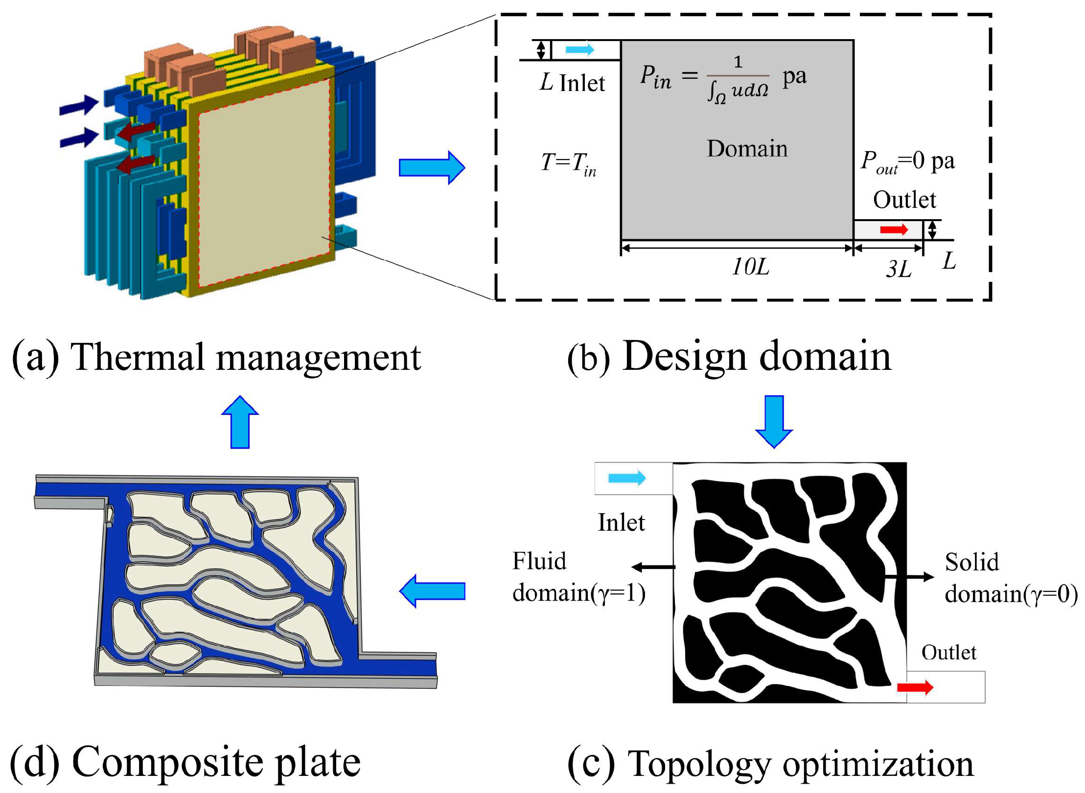
2.1. Physical Model

This study takes the phase change-liquid cooling coupling component of the battery thermal management system as the research object to carry out optimization of the design of the liquid cooling channel. The topology optimization design process is shown in Figure 1. All components are horizontally oriented, and then a thin wall is set between the phase change material and the liquid to prevent the PCM from flowing into the fluid channel. The heat generated by the battery is first absorbed by the phase change material. When the phase change material is completely melted, cooling fluid is introduced to instigate forced convective heat transfer cooling, keeping the phase change material in a solid–liquid two-phase state to maintain steady temperature. The density-based method has been widely applied to fluid topology optimization problems due to its computational efficiency and ease of numerical implementation throughout the iterative optimization process. Originating from the homogenization method, its core concept is to introduce a fictitious material element with variable density—an abstraction not found in actual engineering practice—based on the discretized modeling approach used in topology optimization. In the topology optimization process, the solid isotropic material with penalization (SIMP) method is adopted as the foundational framework. The design domain is discretized into finite elements, with each element assigned a design variable γ.
SIMP:   γ p = γ min + 1 γ min γ   p
When γ = 1, the element represents a fluid channel with no additional flow resistance; when γ = 0, the element represents the PCM, and a large volume force is set in this region to force the flow velocity to approach zero, approximating it as a solid region during flow and heat transfer. The spatial distribution of γ is optimized through an optimization algorithm to obtain the optimum distribution of flow channels and phase change materials.

2.2. Governing Equations

To maintain generality in topology optimization, a flow and heat transfer model is constructed in dimensionless form. Some details are as follows.

2.2.1. Fluid Model

The dimensionless incompressible flow equations are formulated using the dimensionless velocity v * , dimensionless pressure p * , Reynolds number Re , and dimensionless gradient operator * . The definitions of dimensionless variables are as follows [38]:
* = L ,   v * = v V , p * = p ρ V 2 ,   Re = ρ V L μ
where L and V are the characteristic length and characteristic velocity, respectively, and ρ and μ are the fluid density and dynamic viscosity, respectively.
Continuity equation:
  * · v * = 0
Momentum equation:
v * · * v * = * P * I + 1 Re   * v * +   * v * T + F *
where F * is the dimensionless volume force used to express the flow resistance of the porous medium. According to Darcy’s law, F * can be expressed as:
F * = α * v *
where α * is the dimensionless permeability coefficient, which is related to the material in the design domain and can be determined by an interpolation function:
α * ( x ) = α * max q 1 γ q + γ
where q is the penalty factor coefficient, and α * max is determined by the Reynolds number Re and the Darcy coefficient Da [39]:
a * max = 1 + 1 Re 1 Da

2.2.2. Conjugate Heat Transfer Model

The dimensionless heat transfer equation can be constructed using the dimensionless temperature coefficient T * , Prandtl number Pr , dimensionless velocity u * , and Reynolds number Re [30]:
RePr v * ·   * T * =   * 2 T *
0 =   * 2 T * + Q *
where Q * is the heat source. Equation (7) represents the heat transfer equation in the fluid region; Equation (8) represents the solid heat conduction equation. Using the design variable γ , Equations (7) and (8) can be constructed to create a total heat transfer equation:
γ   RePr v * ·   * T * =   * 2 T * + Q *
The definitions of the above dimensionless temperature coefficient T * and Prandtl number Pr are:
T * = T T w T ave T w ,   Pr = μ C P k
where T ave is the average temperature, T w is the wall temperature, and C P and k are the specific heat capacity and thermal conductivity, respectively.

2.3. Optimization Problem

The phase change–liquid cooling composite component involves three main working conditions: (1) a phase-change process without liquid cooling; (2) the solid–liquid two-phase state of PCM, combined with liquid cooling for temperature control; (3) the liquid cooling-driven solidification of phase change materials. For condition (1), whether during the melting or the solidification process, optimization of the flow channel is not required. However, conditions (2) and (3) require optimizing the fluid channel to achieve excellent heat transfer performance and low flow resistance. Since topology optimization while considering the phase-change process leads to extremely high computational costs, and, from a quasi-steady state perspective, the objective functions for heat transfer optimization in different phase change states are consistent (i.e., enhancing heat transfer and reducing flow resistance), the analysis model for topology optimization primarily solves the steady state heat transfer process under condition (2).

2.3.1. Optimization Mathematical Model

To enable the topological flow channels of the liquid cooling to achieve the best cooling performance, one of the optimization objectives of this study is to minimize the average temperature of the design domain. The objective function J th is as follows:
J th = 1 A Ω Td Ω
In addition, to further enhance the cooling efficiency of the liquid cooling plate and reduce power consumption, another optimization objective of this study is to minimize the fluid pressure drop across the cooling plate. The objective function J f is as follows:
J f = Ω 1 s uds d Ω
Meanwhile, to control the size of the solid domain, a volume constraint V f needs to be applied to the solid domain:
V f = Ω γ d Ω Ω 1 d Ω
Then, the overall objective function for topological optimization can be formulated as follows:
minimize Φ = w J th + 1 w J f s . t .   J th = 1 A Ω Td Ω J f   = Ω 1 s uds d Ω V f   = Ω γ d Ω Ω 1 d Ω
where Φ is the total objective function; w is the weight factor.

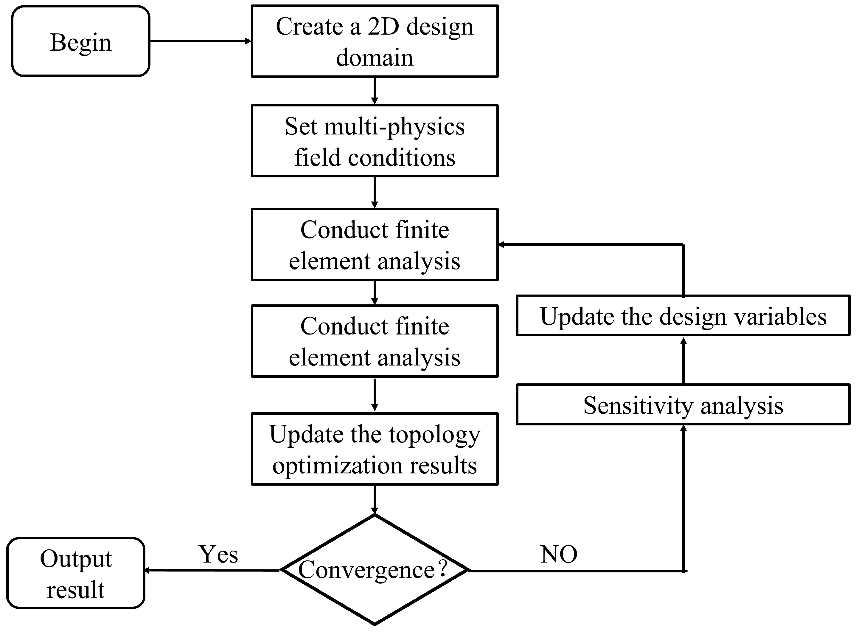
2.3.2. Model Solution

The finite element method is used to solve the flow and heat transfer equations to obtain velocity and temperature distributions. The sensitivity of the objective function can be solved using the adjoint method, and the spatial distribution of design variables is optimized and adjusted using sequential quadratic programming (SNOPT). Multiple iterations are performed until convergence to obtain a stable topological structure, as shown in Figure 2. This process was implemented using the finite element analysis software COMSOL Multiphysics 6.2, with the optimization tolerance set to 1 × 10⁻⁶. This parameter served as the primary convergence criterion for termination, meaning that the optimization was considered to have converged when the relative change in the objective function between two consecutive iterations was less than 1 × 10⁻⁶, indicating that a stable solution had been reached. Additionally, the maximum number of iterations was set to 100, and a relative tolerance of 1 × 10⁻³ was specified for each topology optimization iteration. This ensured that the solution for the physical fields after each design variable update had sufficient accuracy, thereby guaranteeing the reliability and stability of the optimization process.

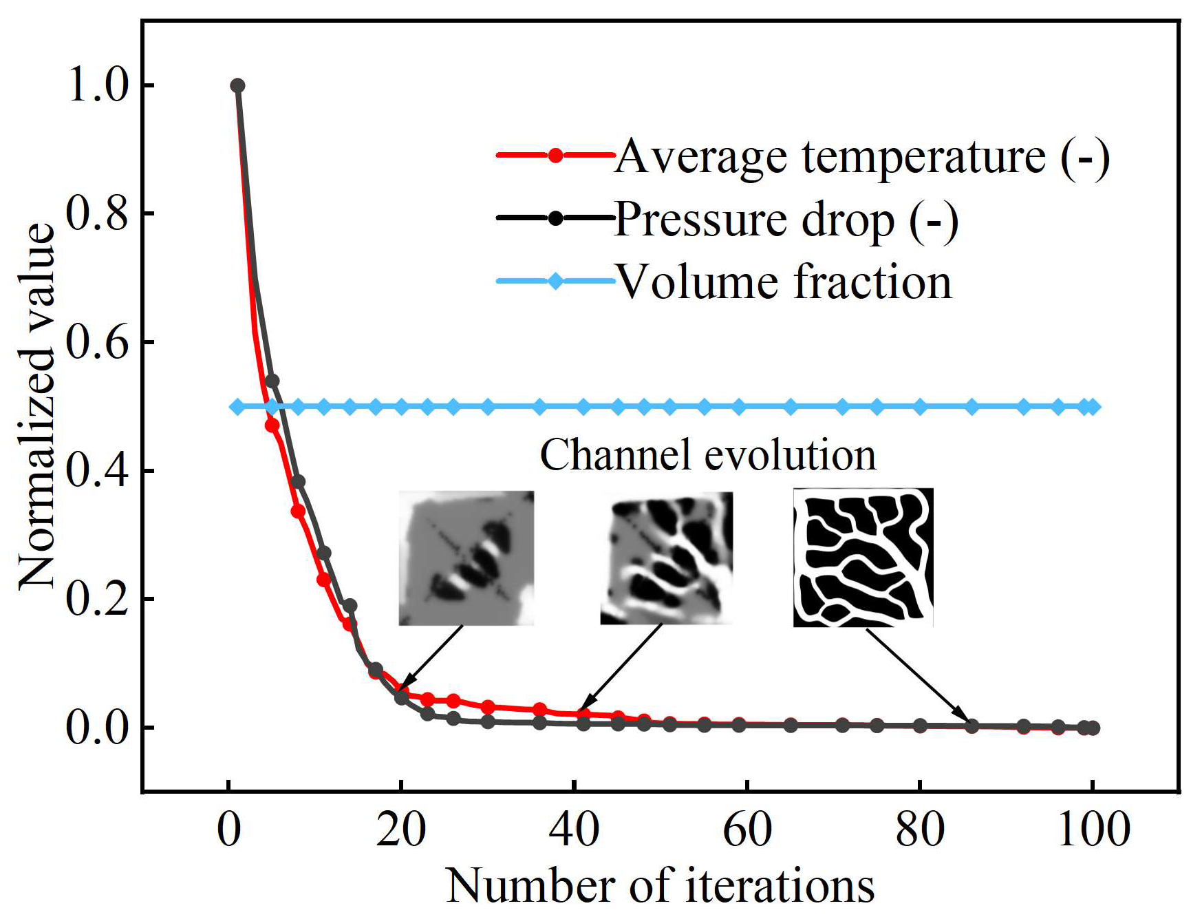
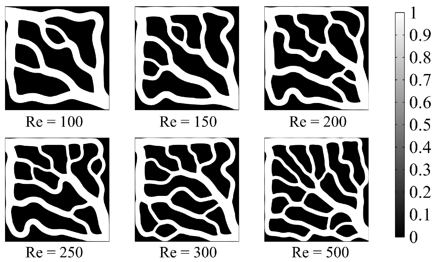
2.4. Analysis of Topology Optimization Results

The parameters of the topology model are depicted in Table 1. Taking the volume fraction Vf = 0.5 as an example, the objective function during the iteration process and the channel evolution are shown in Figure 3. Topological channel structures with Reynolds numbers (Re) of 100, 150, 200, 250, 300, and 500 are generated, and the results are presented in Figure 4. As the Re increases, the liquid cooling channels exhibit more branches and finer flow paths, a structure that facilitates the homogenization of velocity and temperature distributions.
Figure 5 shows the average temperature and pressure drop of topological channels at different Reynolds numbers. With the lower Reynolds numbers, the average temperature of the liquid cooling plate decreases significantly, but after the Reynolds numbers exceed 300, the rate of average temperature decline becomes slower, indicating that the enhancement of the cooling plate’s heat dissipation performance tends to plateau at high Reynolds numbers. Although the higher Reynolds numbers yield a lower average component temperature, excessive branch flows result in higher flow resistance and increased pressure drop. Considering the comprehensive cooling performance and the practical challenges of modeling and numerical calculation, we selected the topological channel with a Reynolds number of 300 for subsequent numerical analysis in the following simulations, aiming to reduce computational costs while ensuring cooling efficiency.

3. Phase Change Liquid Cooling Coupled Heat Transfer Model

3.1. Phase Change Heat Transfer Model

3.1.1. Governing Equations

Since the natural convection velocity of the PCM liquid phase during the phase-change process is much lower than the flow velocity in the liquid channel and has a relatively small impact on the overall heat transfer process, to reduce the computational cost, the natural convection in the phase-change region is neglected. The governing equations describing the flow and heat transfer between the phase change material and the liquid cooling channel are as follows.
Mass equation:
· U = 0
Momentum equation:
ρ u t + ρ ( u   ) u = ( P I + μ ( u + ( u ) T ) )
Energy equation:
ρ C p ( T   ) ( T t + u T   ) ( k ) = Q
where Q is the heat source and k is the thermal conductivity. The specific heat capacity of the PCM needs to be expressed as a function of temperature [40]:
C p ( T ) = C ps + ( C pl C ps ) f + L h D ( T )
where C ps is the solid-phase specific heat capacity of the phase change material, and C pl is the liquid-phase specific heat capacity; f is the liquid fraction, with 1 representing the liquid state and 0 representing the solid state; Lh is the latent heat of phase change, and D(T) is the specific heat capacity correction term [41], expressed as follows:
D T = e T T m ( Δ T PCM / 4 ) 2 π   ( Δ T PCM / 4 ) 2
where Δ T PCM is the temperature range for the phase change material when transitioning from solid to liquid.

3.1.2. Mesh Independence Verification

The solidification of PCM is a dynamic process that varies with time. A fully coupled method is used for transient numerical simulations. Free triangular meshes are used to discretize the topological liquid cooling plate. Considering the complexity of the topological channels, angle refinement and boundary layers are used to refine the mesh of the topological channels. The minimum included angle between boundaries is 240°, and the element size scale factor is 0.25. The mesh generation result of a conventional topological liquid—a cooling plate where Re = 300—is shown in Figure 6.
To ensure the reliability of the numerical simulations and determine an appropriate mesh size to improve the accuracy of numerical calculations, this paper conducts independent numerical calculation studies on the variations in the PCM liquid fraction with time using three types of meshes with mesh sizes of 1 mm, 2 mm, and 3 mm, respectively. The results are shown in Figure 7. During the phase change solidification process, the liquid fraction curves obtained under mesh sizes of 1 mm, 2 mm, and 3 mm almost overlap, indicating that the attenuation trend of the liquid fraction over time remains consistent across the different meshes. The errors in the liquid volume fractions at the same time nodes are all less than 1%, suggesting that the mesh size has a minor impact on the calculation results, i.e., the calculation has achieved grid independence. Therefore, to ensure the accuracy of numerical calculations and a reasonable calculation time, a mesh size of 2 mm is selected for subsequent numerical simulations, with the number of mesh elements being 517,954.

3.2. Experimental Validation

The experimental testing system is shown in Figure 8. A heating plate was tightly attached to the bottom of the liquid cooling plate using thermally conductive silicone to simulate the heat source. The temperature of the heating plate was regulated and stabilized by a precision temperature controller to ensure the consistency and controllability of the heat flux input during testing. As the coolant flowed through the liquid cooling plate, the coolant absorbed heat from the heating plate and was then discharged through the outlet, returning to a thermostatic water bath to complete the closed-loop cycle. A flowmeter was used to measure the flow rate and monitor real-time velocity. A YB-80A precision digital pressure gauge was connected at the inlet and outlet of the cooling plate to measure real-time pressure. A high-resolution infrared thermal imager (Guide-IPM384, 640 × 512 resolution, 12 μm pixel size, and thermal sensitivity ≤ 50 mK) was employed to capture non-contact temperature distribution images of the cooling plate surface, providing a visualization of the overall temperature field. Four K-type thermocouples (accuracy ±0.1 °C) were inserted into the temperature measurement holes of the cooling plate, then their readings were collected by a JK3000 24-channel temperature acquisition system (accuracy 0.5% ± 1 °C), which was connected to a computer for process control and data recording. A ball valve and a needle valve were used to perform coarse and fine adjustments of the flow rate, respectively. The coolant was driven from the thermostatic water bath to the PCM–liquid cooling system by a pump. Flexible PVC hoses were used for piping, and all pipelines were thermally insulated.
As shown in the simulated and experimental curves of the average temperature change recorded during the PCM solidification process depicted in Figure 9, the two curves exhibited a generally consistent trend, with an overall deviation of less than 1%, which falls within a reasonable range. This validates the accuracy of the numerical simulation results.

4. Performance Comparison Between Topological Channels and Conventional Channels

4.1. Physical Model

This section details the comprehensive cooling performance comparison made between the topological-channel liquid cooling plate and the conventional direct current-channel liquid cooling plate. The structure of the cooling plate is shown in Figure 10, with the topological liquid cooling plate exemplified by a conventional topological structure at Re = 300. The blue region represents the flow channel, the shell is made of aluminum metal, the coolant is water, and the milky white region is the solid domain filled with PCM. A thermal, thick approximation multi-layer shell exists between the PCM and the flow channel. The fluid volume-to-design domain volume ratio of the conventional channel is identical to that of the topological structure, with paraffin being used as the material. At the inlet, L = 15 mm. The cooling plate consists of multiple parallel channels with the same width at the inlet and outlet, where the width of each middle parallel channel is a = 10.4 mm and the number of channels is five. The PCM fills a rectangular area with a height of b = 130 mm between adjacent channels, while the top and bottom channels have a width of c = 10 mm, and the thickness of the liquid cooling plate is 10 mm. The thermophysical properties of the materials used in this study are listed in Table 2. Transient numerical simulations were carried out to examine the dynamic behavior of the solid–liquid phase interface during the phase-change process and to assess the comprehensive cooling performance of the cold plate. For better observation of the phase-change process, a two-dimensional model was adopted to handle the phase-change solidification. The initial condition that was set is that the phase change material is completely melted, with the initial temperature of the liquid cooling plate set to 50 °C. Coolant is then supplied at 25 °C for cooling, with an inlet velocity of 0.05 m/s and a static pressure outlet that suppresses backflow.

4.2. Phase Change and Temperature Distribution Characteristics

Figure 11 illustrates the time-dependent solid–liquid phase change interfaces of PCM during the solidification process in conventional and topological liquid cooling plates. Under identical cooling durations, the topology-optimized liquid cooling plate accelerates the phase transition from liquid to solid in PCM more effectively than the conventional design, demonstrating superior cooling performance. Upon coolant introduction, PCM solidification is initiated, with both configurations exhibiting the preferential solidification of PCM near the flow channels, forming a boundary with the liquid phase in the central region. As heat is dissipated, the liquid–solid interface propagates inward. The conventional liquid cooling plate’s regular channel geometry restricts coolant flow, concentrating heat transfer near the channels and resulting in weak central cooling and slow PCM solidification. In contrast, the topological design features a more uniform distribution of PCM regions and flow channels, promoting homogeneous coolant flow, increasing the heat transfer area, and significantly enhancing the solidification rates. This structure also ensures more uniform cooling and mitigates localized cooling deficiencies. As shown in the liquid-phase volume fraction plot in Figure 12, the PCM in the conventional plate achieves full solidification at 29 min, whereas the topological plate achieves complete solidification at 23 min—a 17.2% reduction in solidification time.
The phase change solidification processes of the phase-change liquid cooling plates with either conventional or topological channels are shown in Figure 13. When completely melted, the conventional liquid cooling plate exhibits a maximum temperature of 58.7 °C and an average temperature of 43.6 °C, while the topological liquid cooling plate shows values of 52.7 °C and 39.3 °C, respectively. The maximum temperature is 10.22% lower, and the average temperature is 9.86% lower for the topological design, which can be attributed to the enhanced thermal conductivity uniformity enabled by the dispersed configuration of topological channels. After 21 min of cooling, the average temperatures of the conventional and topological plates are 25.4 °C and 24.5 °C (a temperature difference of 3.5%), with maximum temperatures of 31.3 °C and 26.5 °C (a difference of 15.3%), respectively. The superior heat dissipation capability of the topological plate can be attributed to its complex channel configuration, increased heat exchange surface area, and uniform coolant flow distribution.

4.3. Resistance Characteristics

Figure 14a,b presents the velocity streamline diagram of the liquid cooling plates. It can be observed that the absence of branching and interactions between flow channels in the conventional design causes flow separation and secondary vortices at the corners of parallel channels, resulting in lower flow velocities in the central region. In contrast, the topological optimization generates flow channels with the flow splitting between the main channels, forming secondary flow paths that guide the coolant direction. The fine distribution of secondary branches enables a relatively uniform velocity distribution across the transverse channels, optimizing the coolant flow path. Figure 14c,d presents the pressure distribution nephograms of the liquid cooling plates. The conventional design exhibits non-uniform pressure distribution within the coolant flow with significant local pressure gradients, particularly at channel bends. The overall inlet–outlet pressure loss for the conventional plate is 25.60 Pa. In the topological design, the coolant pressure distribution follows a uniform gradient, and the pressure loss is 15.80 Pa, which is 38.28% lower than that of the conventional design.
Figure 15a presents the pressure drop as a function of time, demonstrating that an increase in inlet velocity leads to a significant rise in the pressure drop (ΔP) of the liquid cooling plate. Pumping power is typically used to quantify the energy consumption required for the coolant to overcome flow resistance; a lower pumping power indicates reduced overall energy consumption of the cooling system. Figure 15b illustrates the pumping power (Ppump) curves. The pumping power for the conventional design is 1.92 × 10⁻⁴ W, while that for the topological design is 1.19 × 10⁻⁴ W. The topological design achieves 38.02%. Within the investigated flow velocity range, both the pressure drop and the pumping power of the topologically optimized liquid cooling plate are significantly lower than those of the conventional design. The reduced pressure loss of the coolant in the optimized flow channel effectively minimizes flow resistance, thereby decreasing the required pumping power and enhancing the overall energy efficiency of the cooling system.
The combined evaluation of pressure drop and pumping power further confirms the advantages of topology optimization in the design of liquid cooling plates. However, increasing the inlet velocity and, consequently, the flow rate leads to a higher pressure drop and a substantial rise in pumping power, which may result in excessive system operating costs.

4.4. Heat Transfer Performance

The important indicators for a more objective and comprehensive evaluation of overall cooling capability, such as the average convective heat transfer coefficient hw [42] and comprehensive performance factor j/f, are illustrated in the Supplementary Materials. Figure 16a,b presents the curves of flow velocity effects on Tpcm, ave, hw, and j/f for the liquid cooling plates. As the inlet velocity increases, the thermal boundary layer thickness of convective heat transfer decreases, enhancing the convective heat transfer capability of the coolant and significantly improving the average convective heat transfer coefficient hw of the liquid cooling plate. At a flow velocity of 0.05 m/s, the topology-optimized liquid cooling plate exhibits hw = 1319.6 W/(m2·K) and j/f = 0.56, representing improvements of 60.71% and 47.5% compared to the conventional design. This indicates that the flow channel structure of the topology-optimized plate enhances fluid heat transfer capacity, and the efficient heat transfer path design significantly boosts system cooling efficiency. Furthermore, when the flow velocity increases from 0.05 m/s to 0.2 m/s, hw of the topology-optimized plate increases by 38.65%. Notably, the largest temperature drop in the PCM within the liquid cooling plate occurs when the flow velocity increases from 0.05 m/s to 0.1 m/s (a decrease of 1.31 °C), whereas further quadrupling the flow velocity to 0.2 m/s only yields a 0.62 °C temperature drop. This is attributed to the low thermal conductivity of paraffin (0.2 W/m·K), which limits heat transfer from the PCM interior to the liquid cooling channel walls. At this point, the j/f factor also decreases, with a reduction of 57.14%, indicating that the increase in flow velocity leads to a decline in the overall performance of the liquid cooling plate. Specifically, when the flow velocity increases from 0.05 m/s to 0.1 m/s, the Reynolds number increases accordingly, enhancing the convective heat transfer capability of the coolant, resulting in a 27.69% improvement in the heat transfer coefficient (hw). However, since the Reynolds number increases by 100%, the denominator in the j factor grows faster than the numerator, leading to a decrease in the j value and, ultimately, a reduction in the j/f factor. Therefore, the cooling performance is not solely determined by the convective heat transfer capability of the fluid but is also limited by the thermal response rate of the PCM. The primary reason for this limitation is that the PCM has low thermal conductivity, making it difficult for the released latent heat to be efficiently conducted to the heat transfer interface, thereby confining the solidification behavior to the interface layer. In addition, excessively high flow velocities can lead to increased pressure drop and energy consumption. Taken together, with high Reynolds numbers, the overall performance of the phase change liquid-cooled composite plate may actually deteriorate. This finding is consistent with the conclusions reported by Guo [43] and Wei [44].
Figure 16c shows the variation curve of Tpcm, ave during the solidification process of PCM in the liquid cooling plates. Throughout the solidification process, the Tpcm, ave of the topology-optimized liquid cooling plate remains lower. The maximum difference in Tpcm, ave between the designs reaches 3.6 °C, with the topological design being approximately 12.3% lower. When Tpcm, ave in the liquid cooling plate stabilizes, this signifies the onset of the two-phase equilibrium region. The topology-optimized liquid cooling plate reaches the two-phase state at 32 min, which is 37.3% faster than the conventional cooling plate.
In practical applications, heat sources such as electronic devices, power batteries, and chips often exhibit time-varying power outputs, where temperature fluctuations can affect the thermal fatigue life of phase change materials, and so cooling systems must ensure temperature stability. Therefore, the steady-state regulation capability of the liquid cooling plate is also critical; this refers to the ability of the phase change liquid cooling system to maintain a stable average temperature under transient thermal loads. Figure 16d presents the temperature variation when subjecting the liquid cooling plates to a fluctuating heat source. Benefiting from superior heat transfer performance and temperature uniformity, the topology-optimized liquid cooling plate demonstrates better thermal response characteristics and steady-state regulation capability under transient heat loads, outperforming the conventional design.

5. Conclusions

A two-dimensional topological model with a dual-objective function (minimizing average temperature and pressure drop) was established using the variable density material interpolation method to investigate the influence mechanism of different Reynolds numbers on the structural characteristics of topological channels. A two-dimensional transient thermo-fluid model was developed, integrating the solid–liquid phase-change process with the coupling of coolant flow and heat transfer. The model was used to compare the flow characteristics, temperature behavior, phase change properties, and stability of fluctuating thermal loads between the topologically optimized liquid cooling plate and the conventional direct-flow liquid cooling plate, leading to the following conclusions:
(1)
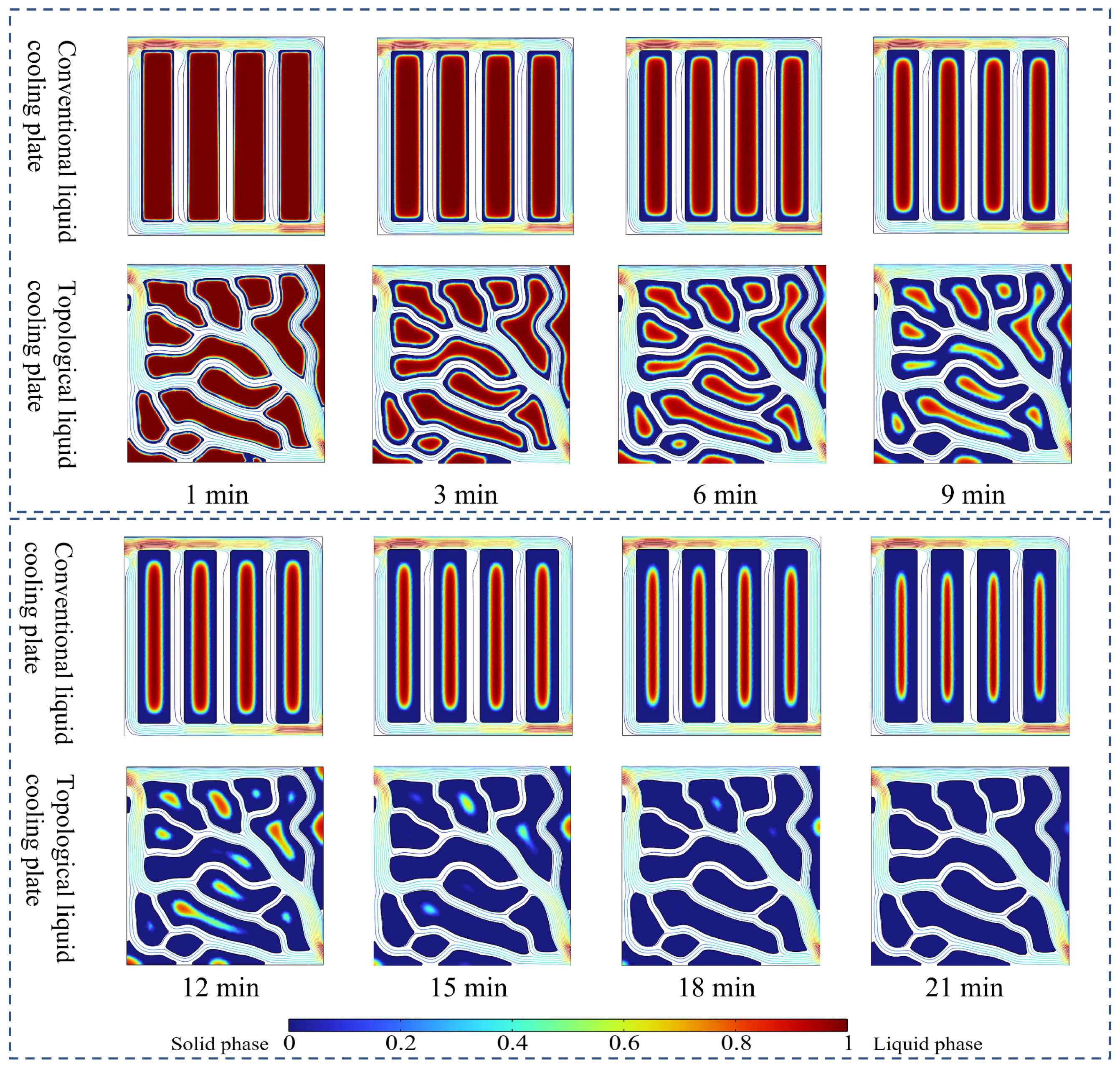
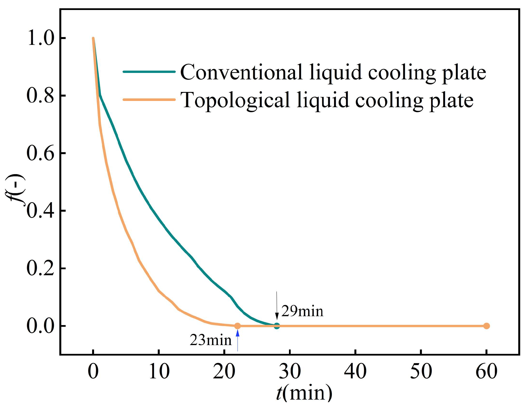
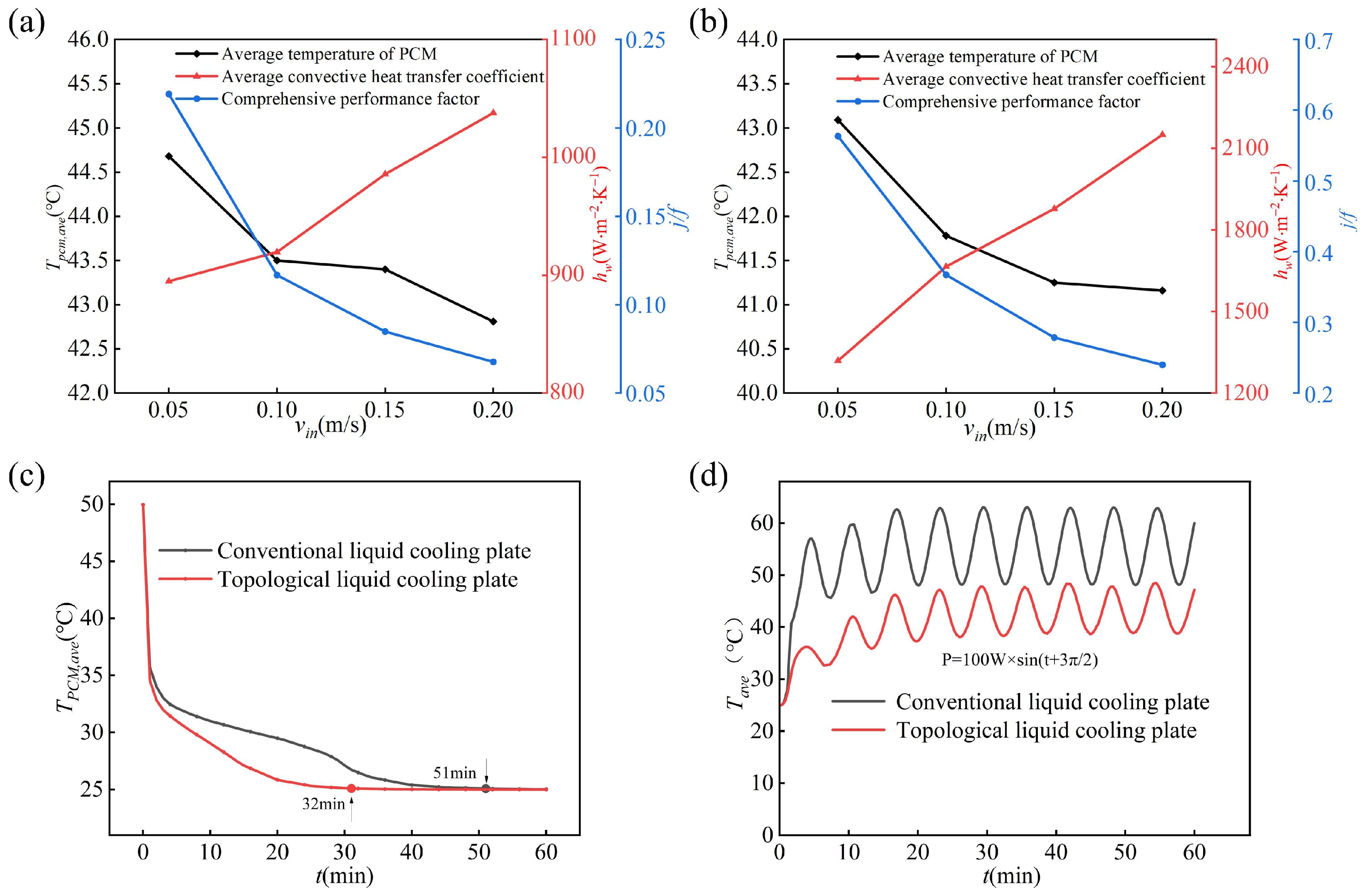
During the phase change solidification process, the PCM in the conventional and topological liquid cooling plates reached full solidification at 29 min and 23 min, respectively, with the topological design reducing the complete phase change solidification time by 17.2%. This can be attributed to the discrete phase change regions of the multi-branch structure, which shortened the thermal conduction distance of the phase change material and accelerated the phase-change process.
(2)
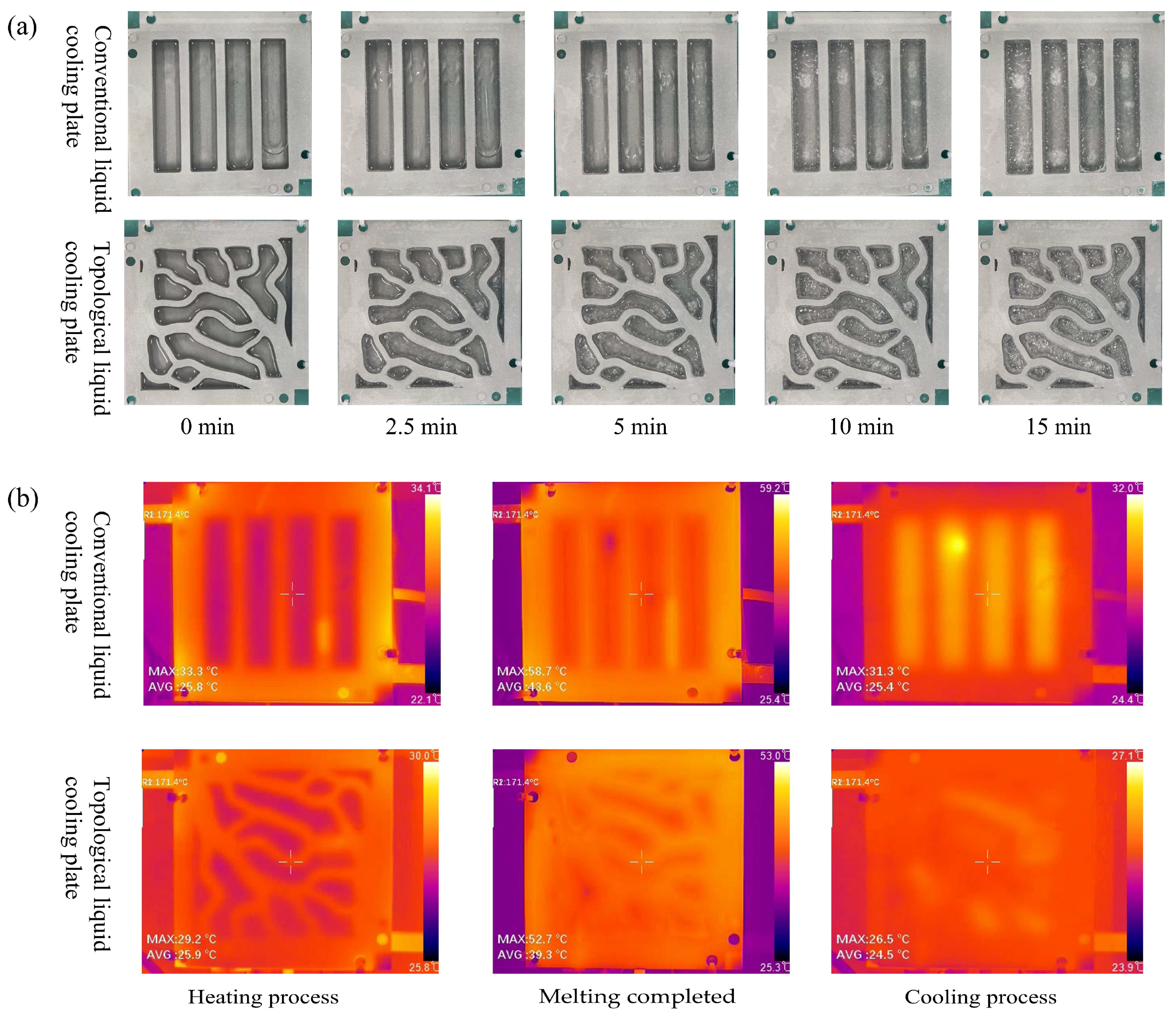
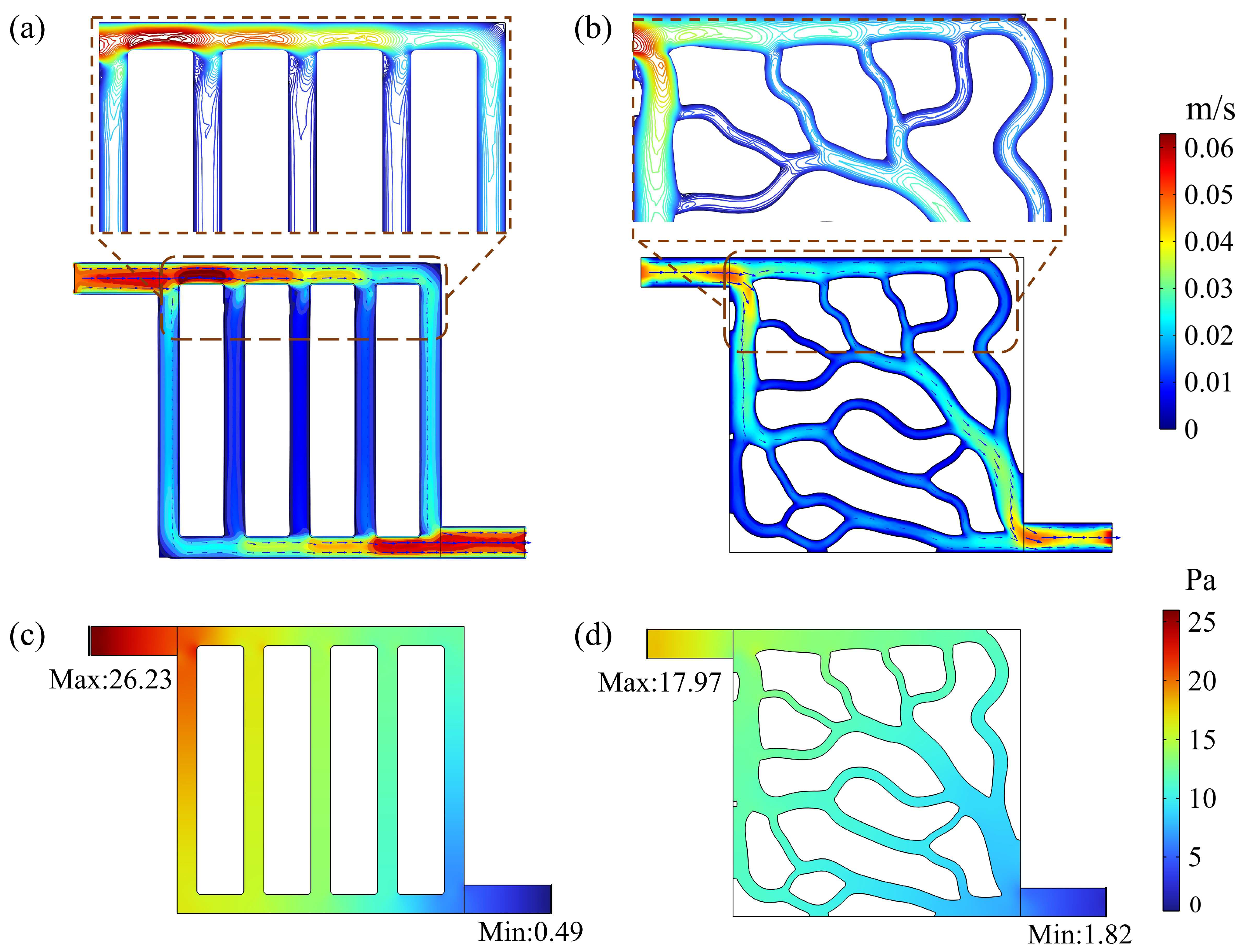
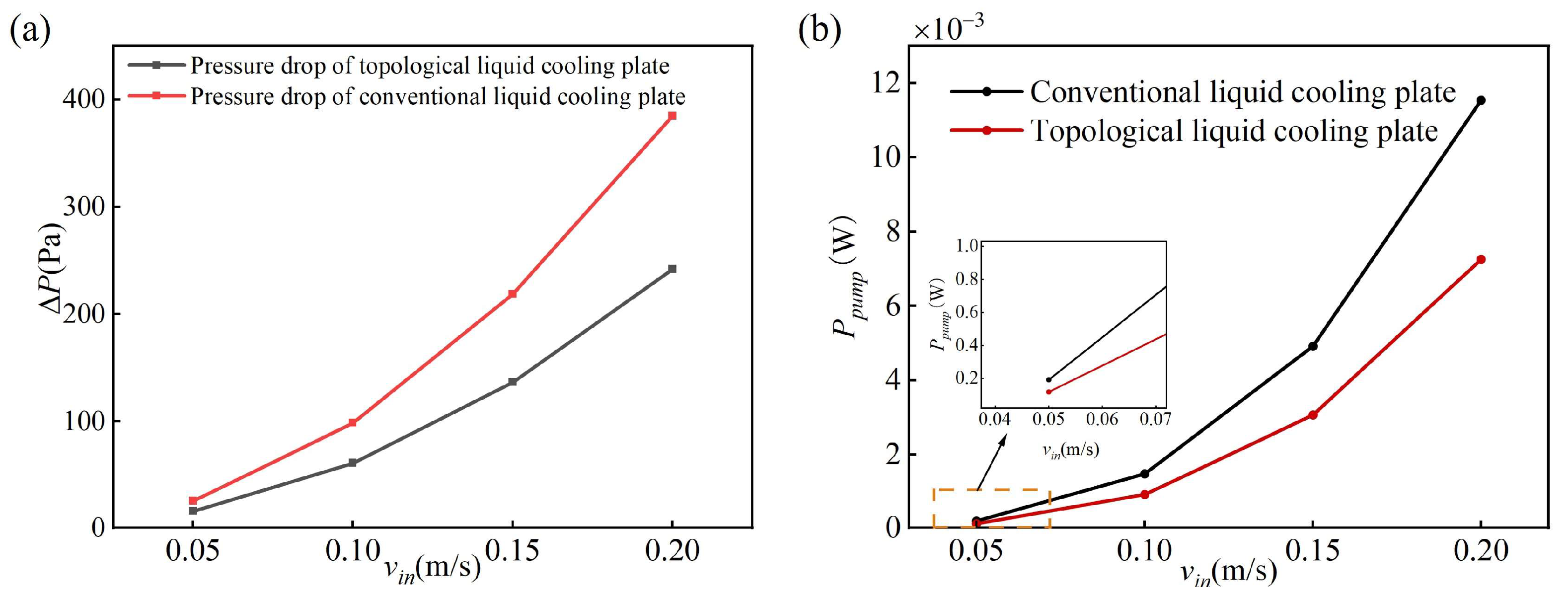
The pressure drop (ΔP) and pumping power (Ppump) of the topologically optimized liquid cooling plate were 38.28% and 38.02% lower, respectively, compared to the conventional liquid cooling plate. This indicates that the flow channel structure of the topologically optimized liquid cooling plate allows for more uniform coolant flow, resulting in smaller pressure losses within the channels. This effectively reduces flow resistance, thereby lowering the pumping power requirement and improving the overall energy efficiency of the cooling system. The experiments show that when the PCM in the liquid cooling plates had completely melted, the conventional plate exhibited maximum and average temperatures of 58.7 °C and 43.6 °C, while the topological plate showed 52.7 °C and 39.3 °C (10.22% and 9.86% lower, respectively). This demonstrates that the topological design achieves a more reasonable structural PCM distribution, effectively suppresses local heat accumulation, and enhances the thermal equilibrium capability of the phase change system.
(3)
During the cooling process, the average temperature of the phase change material (PCM) in the topology-optimized liquid cooling plate was lower by 3.6 °C than that of the conventional design. At a flow velocity of 0.05 m/s, the average convective heat transfer coefficient hw of the topologically optimized liquid cooling plate reached 1319.06 W/(m2·K), which was approximately 47.5% higher than that of the conventional liquid cooling plate (894.876 W/(m2·K)). As the flow velocity increased from 0.05 m/s to 0.2 m/s, hw further improved by 38.65%. However, Tpcm,ave decreased by only 0.62 °C. This limited temperature reduction is primarily attributable to the low thermal conductivity of paraffin (0.2 W/m·K), which restricts effective heat transfer within the PCM. Moreover, the increase in flow velocity led to a significant decline in the overall performance factor j/f, which dropped by 57.14%. This suggests that while enhanced convection improves heat transfer, it also substantially increases system energy consumption, thereby reducing the overall thermal performance. This is because the cooling performance of the liquid cooling plate is not solely determined by the convective heat transfer capability of the coolant but is also constrained by the thermal response rate of the PCM. Due to its limited thermal conductivity, the latent heat released within the PCM cannot be conducted rapidly to the heat exchange interface, resulting in solidification being confined to the interfacial region. Consequently, when the flow velocity—and, thus, the Reynolds number—increased, Tpcm,ave showed only a marginal decrease. Benefiting from superior heat transfer performance and temperature uniformity, the topology-optimized liquid cooling plate exhibits better thermal response characteristics and steady-state regulation capability under transient heat load, compared to the conventional design.
This study simultaneously optimized the spatial distribution of phase change materials and the topology of the liquid cooling channels through topology optimization, thereby enhancing the phase change rate, promoting uniform fluid distribution, and improving temperature uniformity. These results provide a theoretical foundation for the design of phase change–liquid cooling hybrid cold plates. However, several limitations remain. The numerical simulation of the phase-change process is based on a simplified model, which cannot fully capture the complex variations in thermal properties seen under actual conditions. Additionally, these topologically optimized structures are complex to fabricate, relying heavily on 3D printing technologies and incurring relatively high material costs. The long-term thermal stability of the PCM under multiple thermal cycles and varying climatic conditions, as well as the structural durability of the optimized design, still require further investigation.
Looking ahead, the development of topology optimization techniques in thermal management is evolving toward deep interdisciplinary integration. The incorporation of machine learning and intelligent algorithms is expected to effectively address the challenge of local convergence in high-dimensional nonlinear optimization problems. Moreover, coupling the existing manufacturing process with advanced fabrication technologies such as additive manufacturing and micro/nano processing will drive the design of thermal management systems toward greater intelligence, precision, and efficiency, offering both theoretical insights and technological breakthroughs for next-generation thermal control systems.

Supplementary Materials

The following supporting information can be downloaded at: https://www.mdpi.com/article/10.3390/en18102652/s1.

Author Contributions

X.X.: Investigation, conceptualization, methodology, software, data curation, validation, visualization, and writing—original draft. J.L. (Jiancheng Luo): Supervision and writing—review and editing. J.L. (Jiabao Li): Investigation, conceptualization, methodology, supervision, project administration, funding acquisition, resources, and writing—review and editing. L.W.: Resources, supervision, and writing—review and editing. All authors have read and agreed to the published version of the manuscript.

Funding

This work was supported by the Natural Science Foundation of Guangxi Province (Grant No. 2025GXNSFBA069178).

Institutional Review Board Statement

Not applicable.

Informed Consent Statement

Not applicable.

Data Availability Statement

The data presented in this study are available on request to the authors and will not be made public, due to privacy and ethical concerns.

Conflicts of Interest

The authors declare that they have no known competing financial interests or personal relationships that could have appeared to influence the work reported in this paper.

References

  1. Lu, H.; Tang, X. A flexible optimization study on air-cooled battery thermal management system by considering of system volume and cooling performance. J. Energy Storage 2023, 72, 108527. [Google Scholar] [CrossRef]
  2. Peng, X.; Cui, X.; Liao, X.; Garg, A. A Thermal Investigation and Optimization of an Air-Cooled Lithium-Ion Battery Pack. Energies 2020, 13, 2956. [Google Scholar] [CrossRef]
  3. Shengxin, E.; Liu, Y.; Cui, Y.; Wu, A.; Yin, H. Effects of composite cooling strategy including phase change material and cooling air on the heat dissipation performance improvement of lithium ion power batteries pack in hot climate and its catastrophe evaluation. Energy 2023, 283, 129074. [Google Scholar] [CrossRef]
  4. Santosh, C.; Jie, L.; Venkateswarlu, B.; Woo, J.S.; Chul, K.S. Numerical simulation of lithium-ion battery thermal management systems: A comparison of fluid flow channels and cooling fluids. J. Energy Storage 2023, 73, 108940. [Google Scholar]
  5. Xu, J.; Chen, Z.; Qin, J.; Pan, M. A lightweight and low-cost liquid-cooled thermal management solution for high energy density prismatic lithium-ion battery packs. Appl. Therm. Eng. 2022, 203, 117871. [Google Scholar] [CrossRef]
  6. Yu, Z.P.; Zhang, J.K.; Pan, W.G. A review of battery thermal management systems about heat pipe and phase change materials. J. Energy Storage 2023, 62, 106827. [Google Scholar] [CrossRef]
  7. Jiang, K.; Liao, G.; E, J.; Zhang, F.; Chen, J.; Leng, E. Thermal management technology of power lithium-ion batteries based on the phase transition of materials: A review. J. Energy Storage 2020, 32, 101816. [Google Scholar] [CrossRef]
  8. Ouikhalfan, M.; Sari, A.; Hekimoglu, G.; Gencel, O.; Tyagi, V.V. Thermal energy storage properties, thermal conductivity, chemical/and thermal reliability of three different organic phase change materials doped with hexagonal boron nitride. Surf. Interfaces 2022, 32, 102176. [Google Scholar] [CrossRef]
  9. Ben Hamida, M.B.; Nguyen, L.M.Q.; Hajjar, A.; Izadi, M.; Sheremet, M.A.; Alrasheedi, N.H.; Hajlaoui, K. Role of applying PCMs on thermal behavior of innovative unit roof enclosure. J. Energy Storage 2024, 77, 109918. [Google Scholar] [CrossRef]
  10. Nguyen, L.M.Q.; Hajjar, A.; Izadi, M.; Sheremet, M.A.; Ben Hamida, M.B. Numerical study on thermal resistance of PCMs incorporated in novel roof structures against energy loss. J. Energy Storage 2023, 74, 109506. [Google Scholar] [CrossRef]
  11. Ben Hamida, M.B. Thermal management of square light emitting diode arrays: Modeling and parametric analysis. Multidiscip. Model. Mater. Struct. 2024, 20, 363–383. [Google Scholar] [CrossRef]
  12. Ben Salah, S.; Ben Hamida, M.B. Alternate PCM with air cavities in LED heat sink for transient thermal management. Int. J. Numer. Methods Heat Fluid Flow 2019, 29, 4377–4393. [Google Scholar] [CrossRef]
  13. Li, W.Q.; Qu, Z.G.; He, Y.L.; Tao, Y.B. Experimental study of a passive thermal management system for high-powered lithium ion batteries using porous metal foam saturated with phase change materials. J. Power Sources 2014, 255, 9–15. [Google Scholar] [CrossRef]
  14. Ye, Y.; Zhang, Z.Y.; Ma, Y.W.; Zhang, Y.Y.; Liu, J.J.; Yan, K.; Cheng, H.H. Performance optimization of hydrogen storage reactors based on PCM coupled with heat transfer fins or metal foams. Int. J. Hydrogen Energy 2024, 92, 392–400. [Google Scholar] [CrossRef]
  15. Izadi, M.; Fagehi, H.; Imanzadeh, A.; Altnji, S.; Bechir Ben Hamida, M.; Sheremet, M.A. Influence of finned charges on melting process performance in a thermal energy storage. Therm. Sci. Eng. Prog. 2023, 37, 101547. [Google Scholar] [CrossRef]
  16. Afaynou, I.; Faraji, H.; Choukairy, K.; Khallaki, K.; Akrour, D. Effectiveness of a PCM-based heat sink with partially filled metal foam for thermal management of electronics. Int. J. Heat Mass Transf. 2024, 235, 126196. [Google Scholar] [CrossRef]
  17. Sheikh, Y.; Hamdan, M.O.; Sakhi, S. A review on micro-encapsulated phase change materials (EPCM) used for thermal management and energy storage systems: Fundamentals, materials, synthesis and applications. J. Energy Storage 2023, 72, 108472. [Google Scholar] [CrossRef]
  18. Yang, Y.; Chen, L.; Yang, L.; Du, X. Numerical study of combined air and phase change cooling for lithium-ion battery during dynamic cycles. Int. J. Therm. Sci. 2021, 165, 106968. [Google Scholar] [CrossRef]
  19. Yu, X.K.; Tao, Y.B.; Deng, Q.Q. Experimental study on thermal management of batteries based on the coupling of metal foam-paraffin composite phase change materials and air cooling. J. Energy Storage 2024, 84, 110891. [Google Scholar] [CrossRef]
  20. Yang, H.; Li, M.; Wang, Z.; Ma, B. A compact and lightweight hybrid liquid cooling system coupling with Z-type cold plates and PCM composite for battery thermal management. Energy 2023, 263, 126026. [Google Scholar] [CrossRef]
  21. Kang, Z.; Wang, X.; Yin, R.; Xu, L.; Wu, J.; Wang, S.; Peng, Q. Optimizing of coupled phase change materials and liquid cooling thermal management for Li-ion battery pack. Appl. Therm. Eng. 2025, 273, 126508. [Google Scholar] [CrossRef]
  22. Kim, S.; Stavins, R.A.; Shoham, E.; Ziskind, G.; Miljkovic, N.; King, W.P. High power transient thermal management with dynamic phase change material and liquid cooling. Int. J. Heat Mass Transf. 2025, 246, 126998. [Google Scholar] [CrossRef]
  23. Yang, W.; Zhou, F.; Zhou, H.; Wang, Q.; Kong, J. Thermal performance of cylindrical lithium-ion battery thermal management system integrated with mini-channel liquid cooling and air cooling. Appl. Therm. Eng. 2020, 175, 115331. [Google Scholar] [CrossRef]
  24. Zhang, Y.; Zuo, W.; E, J.; Li, J.; Li, Q.; Sun, K.; Zhou, K.; Zhang, G. Performance comparison between straight channel cold plate and inclined channel cold plate for thermal management of a prismatic LiFePO4 battery. Energy 2022, 248, 123637. [Google Scholar] [CrossRef]
  25. Chen, Y.; Chen, K.; Dong, Y.; Wu, X. Bidirectional symmetrical parallel mini-channel cold plate for energy efficient cooling of large battery packs. Energy 2022, 242, 122553. [Google Scholar] [CrossRef]
  26. Guo, R.; Li, L. Heat dissipation analysis and optimization of lithium-ion batteries with a novel parallel-spiral serpentine channel liquid cooling plate. Int. J. Heat Mass Transf. 2022, 189, 122706. [Google Scholar] [CrossRef]
  27. Zuo, W.; Zhang, Y.; E, J.; Li, J.; Li, Q.; Zhang, G. Performance comparison between single S-channel and double S-channel cold plate for thermal management of a prismatic LiFePO4 battery. Renew. Energy 2022, 192, 46–57. [Google Scholar] [CrossRef]
  28. Chen, X.; Su, Y.; Zhang, Y.; Shen, J.; Xu, X.; Wang, X.; Zhou, F. Performance of thermal management system based on PCM/forked liquid-cold plate for 18650 cylindrical battery. J. Energy Storage 2024, 91, 112071. [Google Scholar] [CrossRef]
  29. Fan, Y.; Wang, Z.; Fu, T.; Wu, H. Numerical investigation on lithium-ion battery thermal management utilizing a novel tree-like channel liquid cooling plate exchanger. Int. J. Heat Mass Transf. 2022, 183, 122143. [Google Scholar] [CrossRef]
  30. Zhao, D.; Lei, Z.; An, C. Research on battery thermal management system based on liquid cooling plate with honeycomb-like flow channel. Appl. Therm. Eng. 2023, 218, 119324. [Google Scholar] [CrossRef]
  31. Fan, X.; Meng, C.; Yang, Y.; Lin, J.; Li, W.; Zhao, Y.; Xie, S.; Jiang, C. Numerical optimization of the cooling effect of a bionic fishbone channel liquid cooling plate for a large prismatic lithium-ion battery pack with high discharge rate. J. Energy Storage 2023, 72, 108239. [Google Scholar] [CrossRef]
  32. Borrvall, T.; Petersson, J. Topology optimization of fluids in Stokes flow. Int. J. Numer. Methods Fluids 2003, 41, 77–107. [Google Scholar] [CrossRef]
  33. Fawaz, A.; Hua, Y.; Le Corre, S.; Fan, Y.; Luo, L. Topology optimization of heat exchangers: A review. Energy 2022, 252, 124053. [Google Scholar] [CrossRef]
  34. Lurie, S.A.; Rabinskiy, L.N.; Solyaev, Y.O. Topology optimization of the wick geometry in a flat plate heat pipe. Int. J. Heat Mass Transf. 2019, 128, 239–247. [Google Scholar] [CrossRef]
  35. Pietropaoli, M.; Montomoli, F.; Gaymann, A. Three-dimensional fluid topology optimization for heat transfer. Struct. Multidiscip. Optim. 2019, 59, 801–812. [Google Scholar] [CrossRef]
  36. Li, H.; Kondoh, T.; Jolivet, P.; Furuta, K.; Yamada, T.; Zhu, B.; Zhang, H.; Izui, K.; Nishiwaki, S. Optimum design and thermal modeling for 2D and 3D natural convection problems incorporating level set-based topology optimization with body-fitted mesh. Int. J. Numer. Methods Eng. 2022, 123, 1954–1990. [Google Scholar] [CrossRef]
  37. Subramaniam, V.; Dbouk, T.; Harion, J.L. Topology optimization of conjugate heat transfer systems: A competition between heat transfer enhancement and pressure drop reduction. Int. J. Heat Fluid Flow 2019, 75, 165–184. [Google Scholar] [CrossRef]
  38. Li, H.; Ding, X.; Meng, F.; Jing, D.; Xiong, M. Optimal design and thermal modelling for liquid-cooled heat sink based on multi-objective topology optimization: An experimental and numerical study. Int. J. Heat Mass Transf. 2019, 144, 118638. [Google Scholar] [CrossRef]
  39. Kondoh, T.; Matsumori, T.; Kawamoto, A. Drag minimization and lift maximization in laminar flows via topology optimization employing simple objective function expressions based on body force integration. Struct. Multidiscip. Optim. 2012, 45, 693–701. [Google Scholar] [CrossRef]
  40. Ebadi, S.; Al-Jethelah, M.; Tasnim, S.H.; Mahmud, S. An investigation of the melting process of RT-35 filled circular thermal energy storage system. Open Physices 2018, 16, 574–580. [Google Scholar] [CrossRef]
  41. Moench, S.; Dittrich, R. Influence of Natural Convection and Volume Change on Numerical Simulation of Phase Change Materials for Latent Heat Storage. Energies 2022, 15, 2746. [Google Scholar] [CrossRef]
  42. Monika, K.; Chakraborty, C.; Roy, S.; Dinda, S.; Singh, S.A.; Datta, S.P. Parametric investigation to optimize the thermal management of pouch type lithium-ion batteries with mini-channel cold plates. Int. J. Heat Mass Transf. 2021, 164, 120568. [Google Scholar] [CrossRef]
  43. Guo, C.; Liu, H.-L.; Guo, Q.; Shao, X.-D.; Zhu, M.-L. Investigations on a novel cold plate achieved by topology optimization for lithium-ion batteries. Energy 2022, 261, 125097. [Google Scholar] [CrossRef]
  44. Wei, L.-S.; Liu, H.-L.; Tang, C.-G.; Tang, X.-P.; Shao, X.-D.; Gongnan, X. Investigation of novel type of cylindrical lithium-ion battery heat exchangers based on topology optimization. Energy 2024, 304, 131886. [Google Scholar] [CrossRef]
Figure 1. Topology optimization design flow of phase change liquid cooling coupling components.
Energies 18 02652 g001
Figure 2. Topology optimization design flow of phase-change and liquid-cooled coupling components.
Energies 18 02652 g002
Figure 3. The variation curves of the objective function and volume fraction.
Energies 18 02652 g003
Figure 4. Topological structures under different Reynolds numbers.
Energies 18 02652 g004
Figure 5. The average temperature and pressure drop at different Reynolds numbers.
Energies 18 02652 g005
Figure 6. Mesh model of the topological liquid cooling plate.
Energies 18 02652 g006
Figure 7. Mesh independence verification.
Energies 18 02652 g007
Figure 8. Schematic diagram of the experimental system.
Energies 18 02652 g008
Figure 9. Average temperature variation during the PCM solidification process.
Energies 18 02652 g009
Figure 10. Schematic diagram of the liquid cooling plate structure.
Energies 18 02652 g010
Figure 11. The solidification process of PCMs in conventional and topological channels.
Energies 18 02652 g011
Figure 12. Phase change curves of the PCM.
Energies 18 02652 g012
Figure 13. Experimental phase change tests. (a) Phase change solidification process; (b) temperatures of the liquid cooling plates during the phase-change process.
Energies 18 02652 g013
Figure 14. (a) Velocity streamline diagram of the conventional cooling plate; (b) velocity streamline diagram of the topologized cooling plate; (c) pressure nephogram of the conventional cooling plate; (d) pressure nephogram of the topologized cooling plate.
Energies 18 02652 g014
Figure 15. Flow characteristics of the liquid cooling plate. (a) Curve of the flow resistance coefficient versus flow velocity; (b) the curve of pumping power versus flow velocity.
Energies 18 02652 g015
Figure 16. The comprehensive cooling performance of the liquid cooling plate. (a) The comprehensive cooling capacity index of the conventional liquid cooling plate; (b) the comprehensive cooling capacity index of the topological liquid cooling plate; (c) the average temperature of PCM; (d) the average temperature of the liquid cooling plate under fluctuating heat loads.
Energies 18 02652 g016
Table 1. The parameters of the topology model.
Boundary ConditionsParametersValues
Length (mm)L15
Projection slopeβ8
Projection pointθβ0.5
Penalty coefficientq0.01
Inlet temperatureTin0
Inlet pressure (Pa)Pin3.33
Volume constraintVf0.5
Weight factorW0.5
Table 2. Thermophysical properties of the materials used.
Thermophysical PropertiesParaffin (PCM)AluminumWater
Solid density ρs/(kg·m−3)8002700-
Liquid density ρl/(kg·m−3)850-998.2
Specify heat at constant
pressure Cp/(kJ·kg·K−1)
20009004182
Thermal conductivity
k/(W·m−1·K−1)
0.22380.6
Latent heat Lh/(kJ·kg−1)220--
Phase change temperature T/°C37--
Disclaimer/Publisher’s Note: The statements, opinions and data contained in all publications are solely those of the individual author(s) and contributor(s) and not of MDPI and/or the editor(s). MDPI and/or the editor(s) disclaim responsibility for any injury to people or property resulting from any ideas, methods, instructions or products referred to in the content.

