Review

Review of the Present State, Development Trends, and Advancements of Power Electronic Converters Used in Robotics

Department of Electrical Power Engineering and Mechatronics, Tallinn University of Technology, 19086 Tallinn, Estonia
*
Author to whom correspondence should be addressed.
Energies 2025, 18(10), 2638; https://doi.org/10.3390/en18102638
Submission received: 24 April 2025 / Revised: 16 May 2025 / Accepted: 19 May 2025 / Published: 20 May 2025

Abstract

:
This review aims to help researchers, designers, and engineering staff extend operational times and elevate robots’ efficiency. The study represents an up-to-date summary of power electronic converters, their classification, and solutions found by leading robot manufacturers. While some advances have not yet become commonplace in mainstream robotics, their crucial role and promise are evident for expanding automation capabilities in various stationary and mobile applications. The work demonstrates two interconnected directions that are currently applied or are planned to be employed in the future as key factors contributing to reducing losses and accelerating energy transformation. The former direction relates to the implementation of wide bandgap devices that are superior to silicon-based electronics. The second trend concerns the advancements of converter topologies. In this way, the article presents how rectifiers, inverters, and their combinations provide voltage control, current management, and waveform shaping, thereby revealing their potential in improving energy utilisation in industry, transport, agriculture, households, and other sectors of vital activity.

1. Introduction

In light of the growing societal needs in the face of energy scarcity, emerging efficient supply systems are attracting more attention from designers. Numerous challenges for meeting power supply currently comprise a wide range of applications, from a few-watt drivers and sensors to megawatt equipment [1,2].
Robots occupy a prominent place among them. According to [3], over four million industrial robots operate in factories worldwide. By regions, 70% of all newly deployed robots are installed in Asia, 17% in Europe and 10% in the Americas. The growth of robotics accelerates in 2025 and will continue in 2026 and 2027.
As an interdisciplinary science and practice area where energy conversion proves to be an indispensable process, robotics is a subject of numerous systematic reviews, such as in [4,5,6,7,8,9]. They reflect the state of the art and determine the most utilisation trends and advancements in robotic energy systems, aiming to help designers and consumers choose the best supply solutions for specific facilities.
Robots belong to the category of precision machines whose motor drives ensure high torque, good dynamic performance, reliable braking capability, and a wide speed range [10,11]. To power them, developers strive to use the most sustainable green technologies.
Energy is supplied to robots from alternating current (AC) and/or direct current (DC) grids and sources. In mobile robots, the DC rail is usually supported by hybrid storage units composed of a battery (accumulator) and/or fuel cell energy sources (ES) along with additional power sources (PS), such as supercapacitors (ultracapacitors) and/or flywheels (Figure 1) [12]. Photovoltaic (PV) solar cells are also considered a clean energy source for producing DC.
As shown in Figure 1, all storage units are bounded by limited power and energy capacity. The batteries have features of high specific energy at low specific power, life-cycle, capacity of self-discharge, and energy cost. On the other hand, the supercapacitor-based power source exhibits less specific energy, more specific power, fast charging, and a longer lifetime at high self-discharge [5,12,13].
Different PEC configurations that connect them ensure decoupled control and power adjustment (Figure 2). The choice of connection topology varies vastly based on the energy management requirements [14].
Supply energy is shared among robot locomotion, manipulation, and control functional blocks that involve various energy consumers, such as motors, servomechanisms, controllers, sensors, and wireless interfaces. Herewith, their networks are often very complicated due to different supply requirements [15]. Voltage and current conversion from ES and PS to the main consumers and between each other is important in robotics. In [4,9,12,16] and other sources, many examples can be found related to energy exchange between batteries, solar panels, supercapacitors, fuel cells, and flywheels. And given that the robot’s movement, control, and sensing are based on semiconductor components, this implies the need for advanced electronics in every solution designed to provide the shape, magnitude, or other parameters of countless electrical quantities.
Despite the availability of multiple studies in the field of power engineering of robots, little attention is paid nowadays to such remarkable building blocks as power electronic converters (PECs). The main energy resources of robots are usually considered to be their power supply systems, improvements in kinematics, statics, dynamics, actuators, sensors, and optimal motion trajectories, whereas existing and prospective types of PECs used in robotic stations are only briefly listed without peculiarities and novelties in energy conversion in this field. Nonetheless, according to the reviews listed above, PECs play an important role in most robots, including their industrial, mobile, collaborative, and farming representatives, as well as robots for kids, solar- and capacitor-powered robots, roadway cleaning robots, robots for disaster-struck regions, etc. The author of [17], who examines the trends in energy processing, sensing, and communication spheres of robotics, notes that the integration of new technologies cannot be possible without advancements in PECs.
The goal and significance of the current research are to present an up-to-date summary of energy converters used in robots, their classification, and solutions found in the scope of the integration of advanced PECs in robotics. The work identifies the crucial role these systems play in enlarging the capabilities of robotic stations across diverse stationary and mobile applications and explains how the PECs provide voltage control, current management, and waveform shaping, thereby optimising energy utilisation. Consequently, this review objects to encourage researchers, designers, and engineering staff to extend operational times and increase the efficiency of robots.
Inclusion and exclusion criteria for references of this review are essential for ensuring their quality and relevance, helping maintain work integrity. References from reputable journals, books, and academic publications directly relate to robots’ PECs. Most of them are recent to provide up-to-date information, while older sources that have lost relevance are omitted. The included studies have reliable methodologies and clear, reproducible results, while unclear researches are not discussed. Preference is given to peer-reviewed publications to ensure the reliability of the information.
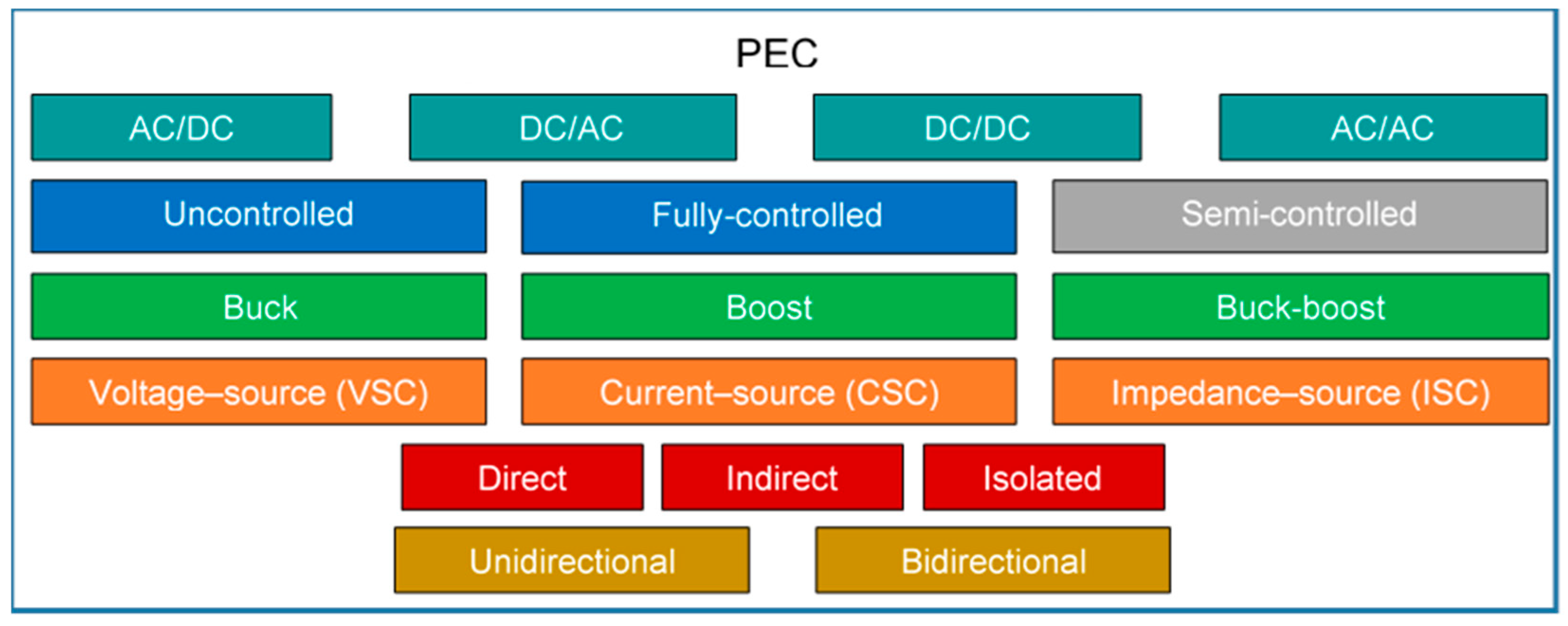
Based on the literature analysis, the general categories of PECs considered in this research can be represented by the diagram shown in Figure 3.
The use of different PECs—rather than a single uniform one—plays a crucial role in enhancing the decoupling of control and power in modern power systems, especially in applications like robots. A breakdown of why this is beneficial may look as follows:
  • Functional decoupling of control and power flow. By selecting the right configuration for a specific application, engineers can isolate control dynamics (like voltage regulation, frequency control) from power transfer dynamics and achieve faster and more stable control loops without being tightly bound to the power flow constraints.
  • Application-specific optimisation. Each PEC topology has strengths suited to different tasks. Voltage source converters (VSCs) are great for fast dynamic response and flexible active and reactive power adjustment. Multilevel converters are needed for high-voltage applications with lower harmonic distortion. Matrix converters are useful for compact, transformer-less designs with bidirectional power flow. Applying different topologies allows tailoring the PEC to the specific control and power needs of various subsystems.
  • Enhanced modularity and scalability. In complex systems such as robots, the use of various PECs makes it possible to independently optimise each module and simplify the expansion or reconfiguration of the system without changing the entire control architecture.
  • Improved control strategies. Different PECs support different control strategies (e.g., direct torque control, vector control, droop control, etc.). This flexibility allows better decoupling of control objectives (e.g., voltage vs. frequency) and hierarchical control, in which local PECs handle fast dynamics, while central controllers manage slower, system-wide objectives.
  • Fault tolerance and redundancy. Using diverse PEC configurations can improve system robustness; when one type of PEC fails or underperforms, others can compensate, whereas different topologies may handle faults differently, improving overall system resilience.
Foremost, all PECs that link AC and DC grids with consumers and with each other can be distributed among four main classes [18]:
  • AC/DC converters called rectifiers that convert input AC voltage to output DC voltage;
  • DC/AC converters called inverters that form an output AC voltage of adjustable amplitude and frequency from an input DC voltage;
  • AC/AC converters that change the AC frequency, phase, magnitude, and shape;
  • DC/DC converters that adjust the DC voltage and current levels.
The PEC may serve as a VSC, current-source converter (CSC), or impedance-source converter (ISC) capable of decreasing (buck) or increasing (boost, buck-boost) voltage level, utilising either uncontrolled (diode-based), fully-controlled (transistor-based), or semi-controlled (thyristor-based) electronic components. Representatives of each class may have direct, indirect (multilevel), or isolated architecture, and their combinations. Depending on the direction of energy flow, PECs can be unidirectional (energy flows only from the supply to the load) or bidirectional (energy may flow either from the supply to the load or from the load to the supply) systems.
An analysis of multiple scientific works and the company’s documentation reveals the presence in robotics of almost all PEC categories shown in Figure 3, except, perhaps, thyristor-based converters.
The following part of the review is devoted to power electronic systems of contemporary robots, novel electronic components, the current state of rectifiers, inverters, AC/AC and DC/DC converters, and their advanced solutions relevant for robotics.

2. Power Electronic Systems of Robots

2.1. Basic Electronics and Suply Arrangement

The most tangible trends of power electronics development in robotics coincide with the general directions in contemporary automation [19,20,21]:
  • improving the performance of all power semiconductor devices;
  • increase of voltage levels supported by changing the thickness and doping of the semiconductor wafer;
  • reduction of switching time by optimizing the device geometry and topology;
  • managing the carrier lifetime;
  • integration of power, control, and protection circuits in a single intelligent chip.
The PEC, as a core of any power electronic system, is traditionally assembled from uncontrolled diodes, controllable transistors, and passive electronic components such as inductors, transformers, capacitors, and resistors. The supply organisation depends on the distinctive static, dynamic, efficiency, accuracy, and other requirements of the customer, including whether energy is to be consumed through a unidirectional circuit or if this energy can be returned to the power source through a bidirectional PEC [18].
Different amounts of energy and specific power are demanded not only for motors and other actuators but also for sensors, communication systems, and similar robot components. Some of these units are power hungry, while others might only operate periodically. Depending on the power ratings, the heavyweight and lightweight robots need different amplitudes and frequencies of AC supply voltage or variable DC energy to be actuated. In any case, an ability to deliver electricity from a source quickly, cleanly, and affordably is required [15].
Heavyweight robots are designed to handle large and bulky loads in automotive, aerospace, shipbuilding, production, and manufacturing spheres. These robots are built to manage tasks that require significant strength and precision, such as lifting and moving big objects, providing both efficiency and safety in industrial environments. A three-phase high-voltage (HV) supply is used in the following examples.
The FANUC M-2000 series can handle payloads up to 2300 kg and has a reach range of up to 4.7 m. According to the manufacturer, they are ideal for picking and palletising heavy parts, such as complete automotive chassis [22]. The KUKA KR FORTEC Ultra series includes robots with payload capacities of up to 800 kg. They are designed for acting in compact spaces and can move large components with high moments of inertia [23]. KAWASAKI M Series robots have payloads ranging from 350 to 1500 kg. They are known for their smart design, suitable for a variety of heavy-duty operations [24].
In contrast, lightweight robots are intended for a high payload-to-weight ratio at low-voltage (LV) supply. By the estimations of [25], the energy consumption of robots such as UR5, FRANKA EMIKA’s FR3, or KINOVA Gen3 is smaller than their heavier, high-payload counterparts; however, most energy (up to 60–90%) is consumed here by electronic components. Therefore, to optimise this group of robots, it is useful to shift towards efficient robot electronic design instead of effective mass distribution or motion control. This is important for industries where minimal weight is crucial, such as in aerospace, medical fields, collaborative applications, and mobile robotics. For example, the DLR Robot III (LWR III) developed by the German Aerospace Center weighs just 14 kg but at the same time can handle loads up to 14 kg, achieving a 1:1 load-to-weight ratio. Its seven-degrees-of-freedom (DOF) manipulator is flexible and suitable for various tasks [26]. The tiny MIT hopping robot, smaller than a human thumb and weighing less than a paperclip, can leap over obstacles and traverse challenging terrains. It uses less energy than usual drones but can carry about 10 times more payload than a similar-sized aerial robot [27]. Modular robots, designed with specific joints to reduce mass and enhance the payload-to-weight ratio, are often used in situations requiring high accuracy and flexibility [28].
To power lightweight robots, a single-phase or single-cell battery is often sufficient. For example, the “scorpion” family robots [29] have a 6 V battery source, and all their electrical motors are directly fed by this battery. Robots with a 14.8 V supply with 14.8 V MX-106R motors have a similar architecture [30]. Nevertheless, most low-power sensors and controllers are supplied with various voltages. Some of them tend to operate at lower levels; even 1.8 V may be sufficient. Sensors designed for battery-fed circuits often fall into the 3.3 V category, while sensors that need more energy or are designed to interact directly with controllers act at 5 V. Many modules, including integrated controllers, prefer a 5 V input, but others operate within the higher span, from 12 to 20 V. In robots with a LV supply, the motors often require boosting to develop sufficient torque. In several low-power PECs, different integrated buck-boost converters are adopted instead of ordinary boosting. Alternatively, in more powerful stations, foremost in industry and transportation, the three-phase supply grids and multi-cell accumulators feed middle-voltage and HV drives. Buck converters reduce this level for controllers and sensors, less powerful than the motors. Herein, input and output circuits of PECs may be either directly linked to each other or galvanically isolated. On the one hand, the above reasoning leads to a decrease in losses under optimal conditions, but at the same time, such a topology is accompanied by the growth in the system size and causes excessive heating [8]. It should be noted that machine efficiency distinctly deviates at different operating points defined by the motion velocity and payload [31]. The overall efficiency of the complete robotic station depends on many factors, and resulting energy losses are heterogeneous at various modes of movements, related electrical current, voltage levels, temperature, etc.
It is a common situation when different PEC topologies are combined in one or another robot. For example, the real challenge of several applications, such as de-icing robots, lies in providing an uninterrupted power supply to make them work during extremely cold or wet weather. To ensure maximum power transfer, an energy harvesting system described in [32] is supplied from an electromagnetic source, and the specific PEC is composed of a single-phase bridge AC/DC converter and a discontinuously conducting back-boost DC/DC converter.

2.2. Introduction of Advanced Electronic Components

Since the beginning of the semiconductor era, silicon (Si) has dominated the electronics world. Si-based metal-oxide semiconductor field-effect transistors (MOSFETs) were exploited successfully until the end of the 20th century. As well, Si-diodes and insulated-gate bipolar transistors (IGBTs) still maintain sufficient performance [33]. At the same time, it is well known that operating voltages of Si-diode-based devices tend to drop to an order of 1 V [18]. At LV, all Si-diodes, including the Schottky ones, have an unacceptably large voltage drop compared to the output voltage. This is especially noticeable at a 3.3 V supply, when this voltage drop leads to losses that grow as the voltage decreases. As calculated in [34], a 0.4 V forward voltage drop of a Schottky diode represents a typical efficiency penalty of about 12%, aside from other loss sources. Likewise, the performance of IGBT-based circuits is limited due to low breakdown voltage (the highest voltage rating of commercial IGBTs is about 6.5 kV [20]) and slow switching [35]. Such intrinsic physical borders set a barrier for achieving higher power conversion performance and incur significant losses, thereby reducing the thermal lifespan and the reliability of both the PECs and the actuators that drive robot mechanisms.
According to [31], total converter power dissipation mainly results from both the resistive losses in conductor paths and the switching losses proportional to the switching frequency of IGBTs, usually about 8 kHz at the pulse-width modulation (PWM) frequency of 30–70 kHz. In [4], a detailed analysis is provided on the converter and load losses and on the strategies to decrease them.
To reduce switching and conduction losses and electromagnetic interference (EMI) of electronic switches, zero voltage switching (ZVS) and zero current switching (ZCS) techniques are utilised in all classes of PECs, namely rectifiers, inverters, AC/AC, and DC/DC converters (Figure 3).
At the same time, power and frequency restrictions and environmental pollution issues encourage manufacturers to pay more attention to new media, aiming to replace conventional silicon. Following the super-junction field-effect transistors (SJ-FETs), a production of wide bandgap (WBG) semiconductors began with gallium arsenide, phosphorus, and indium. The subsequent power electronics epoch is triggered by new advances in disruptive replacement technologies, such as ultra-WBG and three-dimensional (3D) packaging, as well as artificial intelligence (AI)-supported design and maintenance technologies as key enablers [33,36,37]. Due to greater voltage capability, faster switching, higher operating temperature, lower conduction resistance, smaller power dissipation, and better efficiency, WBG devices gradually replace Si-diodes, IGBTs, Si-MOSFETs, and SJ-FETs in robotics [38].
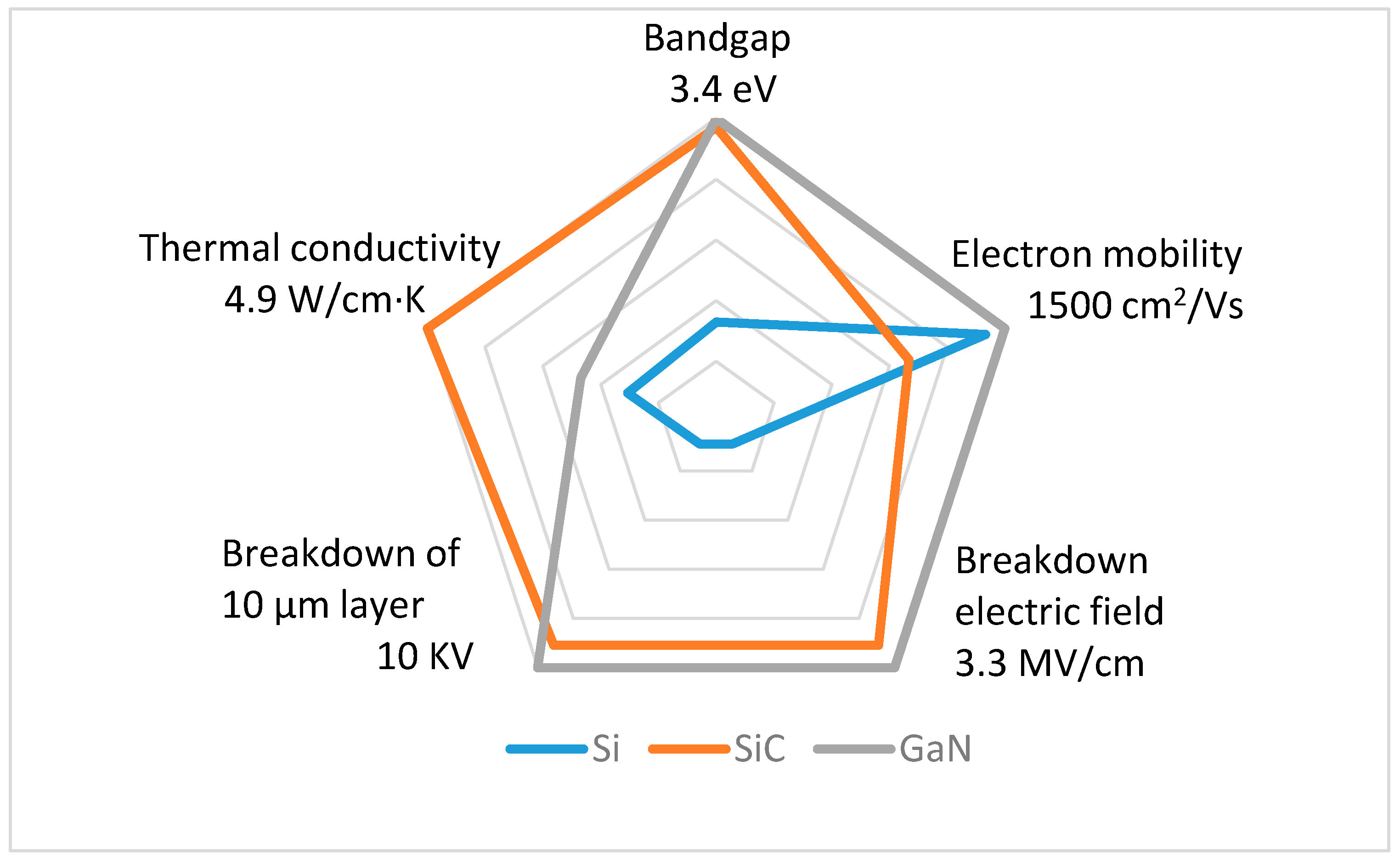
The most popular gallium nitride (GaN) and silicon carbide (SiC) WBG semiconductors are similar in some ways. At the same time, they have a number of significant distinctions. Their comparison was demonstrated in [33,39]. Today, the renewed data are presented (Figure 4) based on sources from 2023 to 2025.
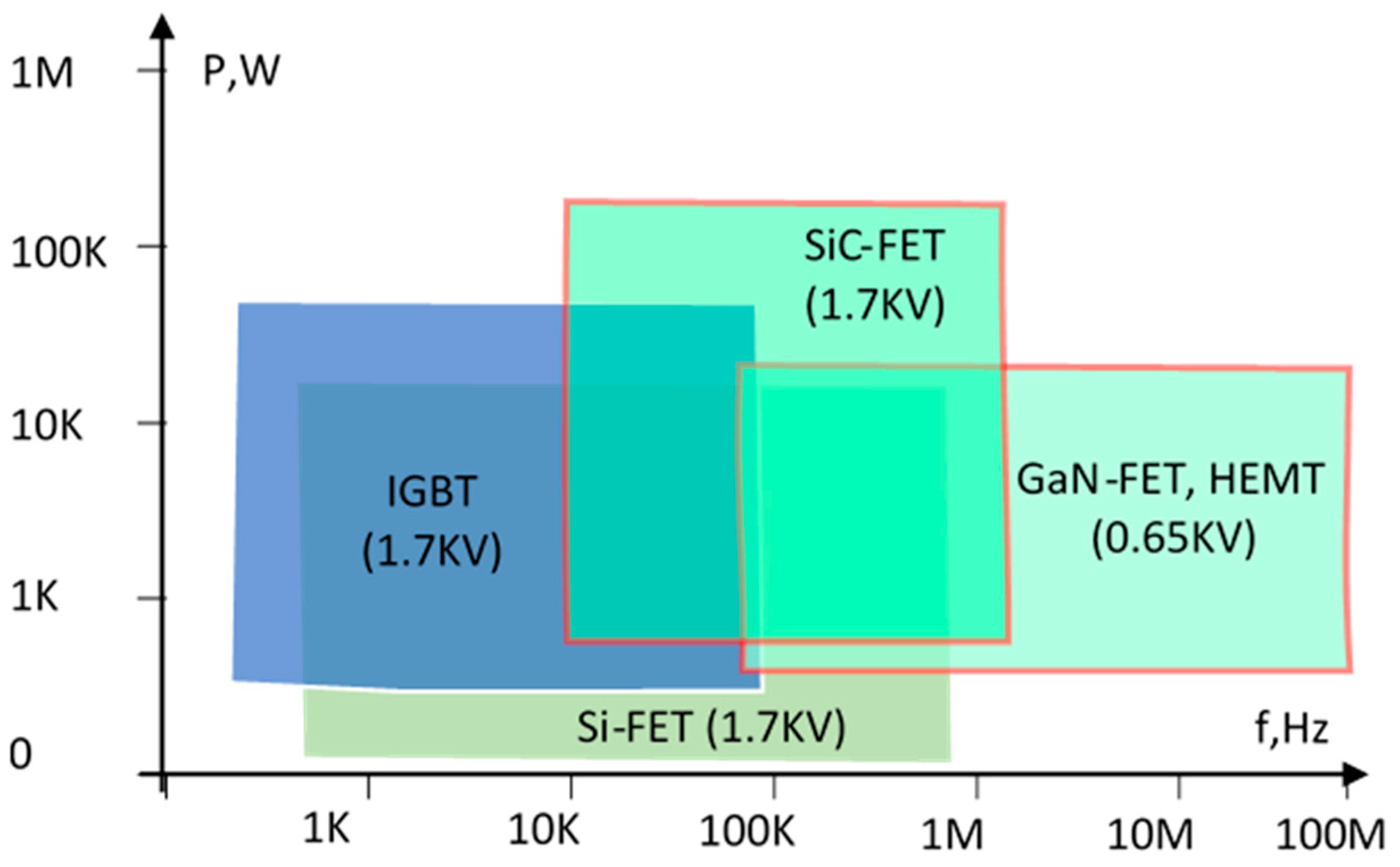
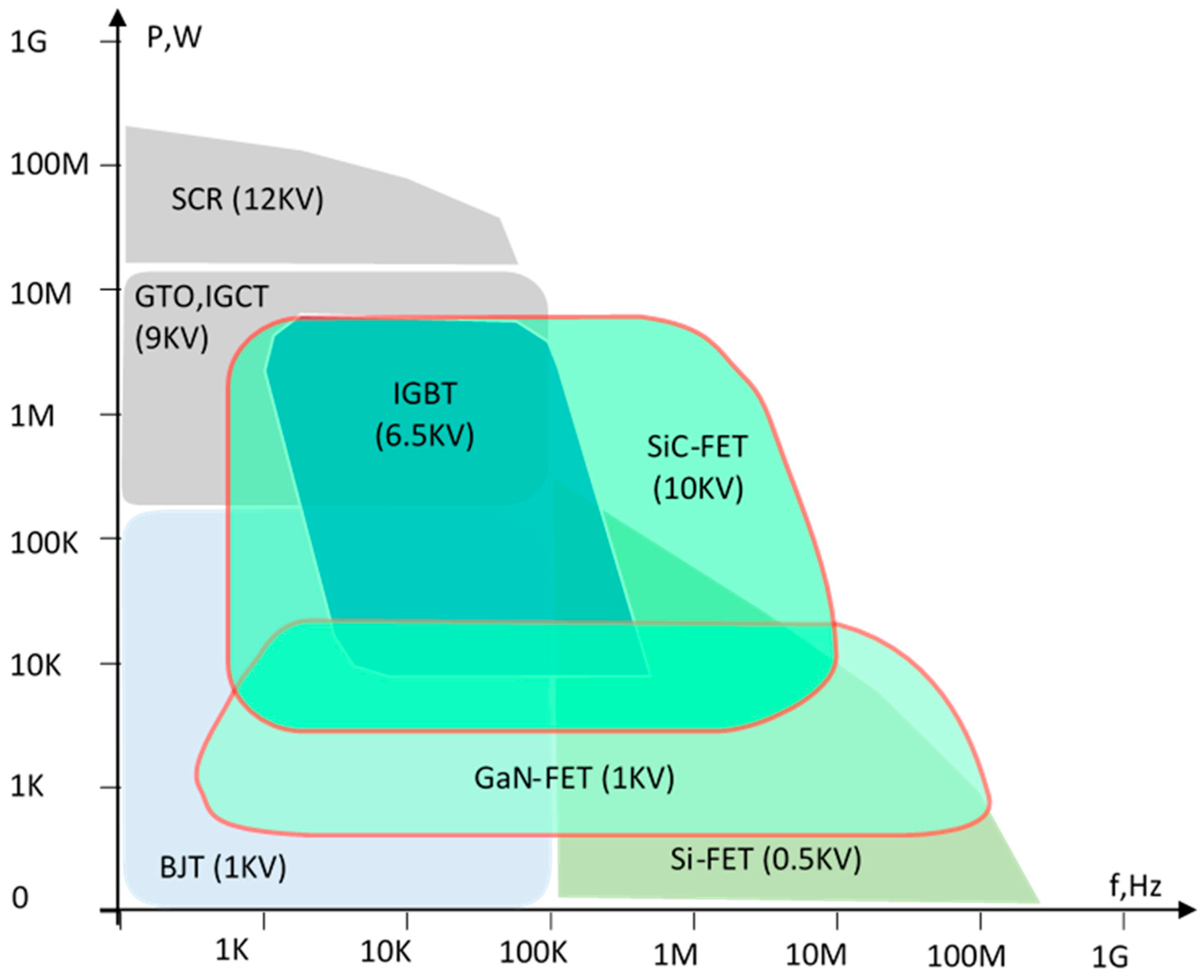
Power-frequency characteristics of Si, SiC, and GaN semiconductor components are also evaluated differently by various researchers depending on production year, testing conditions, cooling environment, etc. According to [39], their ranges look as shown in Figure 5. After comparing many other online resources and company databases where both the commercial and experimental results are presented, a different picture of these dependencies was obtained in this review (Figure 6). In the last diagram, bipolar junction transistors (BJTs) and multiple thyristors are also presented, including silicon controlled rectifiers (SCRs), gate turn-off (GTO) thyristors, and integrated gate commutated thyristors (IGCTs).
WBG-based semiconductor technology enables innovative trends in at least three main areas: energy efficiency and power density, digital power control, and safety of robotic applications [39].
The first direction allows switching frequencies to elevate several times while maintaining efficiency well above 90% and improving form factors by the planar transformers’ adoption. This ensures the packing of more power into smaller kits when manufacturing drives, wireless chargers, and charging stations. The second trend, called power digitalisation, is reflected in the ability of microcontrollers to implement new power management techniques. This trend goes back to 1985, when PECs of the first robots were integrated with bipolar-CMOS/DMOS technology. Later, the Si-MOSFETs, BJTs, and other components, together with non-volatile memory cells, were combined in a single PWM-controlled chip. The third direction calls for the improvement of safety from a human-centric perspective. This evolution of semiconductor technologies plays a key role in the introduction of embedded galvanically isolated protection inside the chips of every separate electronic block, thereby guaranteeing modular safety at the system level.
According to [39], WBG electronics deployment promises the increasing role of robots due to improved efficiency while preserving humans from repetitive tasks. WBG-built robots should become more widespread thanks to new methods based on fast sensors, enhanced environment analysis, object detection, recognition, navigation, and tracking. In particular, there are broad prospects for the use of WBG-based converters on farms, in forestry, and in horticulture due to rising productivity, maintaining the ecosystem for the entire population and reducing the proportion of manual labour. In agriculture, such robots can better identify the state of crops and even determine if they are ready for harvesting.
Another fledgling area of WBG devices is related to soft robotics [40]. The ability to transfer chemically stable WBG materials onto flexible and transparent polymers is valuable for on-site diagnostics and medical treatments, where soft robots can assist with minimally invasive surgeries, whereas traditional surgical tools require large incisions due to their rigidity and bulkiness. To magnify accuracy and effectiveness, these soft robots can be equipped with flexible SiC-based sensors and cameras that can recognise different tissues with the potential for cancer treatment by thermal ablation. In particular, in the case of poor illumination conditions, when recognising different tissues is challenging for surgeons, the impedance sensors provide an alternative in detecting tumour cells when the robot tip contacts tissues. Such an all-in-one surgical robot is capable of biological sensing and medical therapy, where flexible and transparent electronics are well incorporated into the soft actuation system.
It is worth noting that GaN high electron mobility transistors (HEMTs) are an order of magnitude smaller in size, weight, and switching capacitance compared to Si-MOSFETs, while keeping losses acceptably low. In [39], GaN HEMTs are considered a nearly ideal solution for the majority of PECs. Normally off HEMTs have neither the p-n junctions nor the avalanche; therefore, they are preferred in switching applications where they can switch voltage above 1 kV at frequencies up to 100 MHz. Additionally, the GaN structure has an extremely thin electron layer with very high mobility between the drain and source. In [41], GaN-MOSFETs replace Si-MOSFETs in facilities from 48 to 1000 V. Nevertheless, as follows from [42], while the SiC-diodes and SiC-MOSFETs are already employed in advanced robots, the suitability of GaN HEMTs has yet to be verified. Promising news comes from several studies, such as [43], that report advances in monolithic bidirectional switches on GaN FETs, also known as four-quadrant switches.
The advantages of GaN devices are applied primarily in control circuits [43]. Their rapid turn-on and turn-off rates are realised primarily in high-frequency PECs, allowing engineers to utilise smaller and lower-cost inductors and capacitors. The author of [44] introduces the latest generation of GaN-integrated circuits, EPC23102/3/4, for robotic stations composed of a switching leg power stage, a bridge gate driver with bootstrap supply, and several protection chains that simplify the PEC design and ensure a noticeable volume economy. The presented innovative solutions, such as active joints for humanoid robots, vastly improve actuators thanks to their compact and light compositions. Moreover, the renewed drives do not overheat due to minor switching losses of the GaN devices along with lowered BLDC machine losses at higher quality of the supply waveforms. The GaN-based motor drivers for mobile robots described in [17] have very small dimensions and high efficiency, resulting in longer battery lifespan and reduced thermal management requirements. Application of the advanced monolithic 1200 V, 20 A BiDFETs and 600 V GaN-based four-quadrant drives [43] ensures low conduction voltage drop and high switching frequency for bidirectional solutions.
As for the SiC devices, they switch more slowly than GaN [17,33,45]. SiC-MOSFETs combine the advantages of both the IGBTs and the Si-MOSFETs. They have a small on-state resistance at a significant voltage rating (similar to IGBTs) but less switching losses than Si-MOSFETs, which brings them closer to an ideal switch [46]. SiC-MOSFETs also handle more power at faster switching without compromising system efficiency. In PECs used for propulsion in mobile robotics, the PWM frequency grows up to several tens of kilohertz [35]. Even though the SiC-MOSFETs are generally more expensive than Si-MOSFETs, their high-voltage, high-current, and high-frequency capabilities promote the reduction of the size and cost of PEC inductors and transformers. This, in turn, leads to avoiding bulky line filters. The need for cooling also falls, and sometimes such components do not require heatsinks at all [47], resulting in situations where devices of more than 6.5 kV are developed on SiC-MOSFETs without significant losses. In its turn, this reduces robots’ volume, weight, and cost [48].
The key drawback of SiC-MOSFETs is that they require a higher gate voltage than Si-MOSFETs. To turn on a device with a small on-resistance, SiC transistors require a gate voltage of 18 to 20 V, while the same Si-MOSFETs require half the consumption to ensure full conductivity. In addition, to switch off, −3 to −5 V have to be applied to the SiC-MOSFET gate. Special gate driver chips have been developed to resolve these issues.
Considering the great prospects of WBG devices, especially bidirectional GaN switches, the capabilities and efficiency of robotic systems are set to revolutionise robotics in the coming years. Here are some key trends to watch:
  • thanks to increased efficiency and performance, WBG transistors offer reduced power losses and improved thermal management, which are crucial for high-performance robotic applications;
  • the ability of WBG switches to operate at higher frequencies will enable the development of more compact and lightweight robotic systems, enhancing mobility and functionality;
  • since WBG materials are known for their robustness and ability to operate at higher temperatures, this makes them ideal for harsh environments and demanding applications in robotics, where reliability and durability are paramount;
  • the combination of WBG devices with AI technologies promises to enable predictive maintenance and real-time health monitoring of robotic systems.

3. Present State, Development Trends, and Advancements of AC/DC Converters Used in Robotics

3.1. Diode-Based AC/DC Converters in Robotics

AC supply is the most abundant source of electrical energy delivered to industrial and domestic facilities. Although DC batteries are broadly used in robotics due to their portability and steady power supply, most robots cannot live without being permanently or periodically tethered to an external AC grid. For this, non-controlled diode rectifiers are the mainstream solution, while thyristor semi-controlled AC/DC converters are practically impossible to find in modern robotics. To feed DC loads, a variety of diode circuits are used that convert AC to a usable form of DC. According to [9,49], the rectifiers are utilised either as separate devices or as subsystems of other PECs as follows:
  • classical AC/DC converters for direct supply the DC loads from AC grids;
  • front ends of indirect (DC-link) AC/AC converters;
  • back ends of indirect (isolated) DC/DC converters;
  • front ends of bidirectional DC/AC converters.
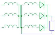
Historically, it has been customary to design rectifier systems on diodes, without voltage regulation. In the absence of transistors or their high cost, diode rectifiers maintain a constant voltage in a range that would eliminate the wasteful need to regulate it. These fixed-ratio AC/DC converters are called uncontrolled rectifiers. The following classical topologies of rectifying circuits are available on the robot market:
  • midpoint (M) and bridge (B) rectifiers;
  • single-phase (M/B1,2) and three-phase (M/B3,6) rectifiers;
  • half-wave (M1) and full-wave (M/B2,3,6) rectifiers.
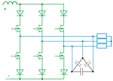
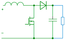
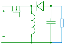
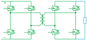
In Table 1 and subsequent tables, PECs are shown in green and loads in blue.
These architectures differ by the shape of the DC signal, root mean square (RMS) input, average output, number of pulses per the supply period, amplitude ripple values of voltage and current waves, as well as their efficiency. The power range of rectifiers is very wide, from watts for compact space-constrained consumer electronics [49] to megawatt-power solutions for heavy-duty robots [23].
The half-wave midpoint topologies are not popular in robot motor drives that require stable and reliable power supplies. Nevertheless, they are implemented in several robotic blocks operated at the single-phase supply with a neutral point or without it, with a centre-tapped transformer or without it. In soft robots that mimic animal anatomy and behaviour [50], a half-wave Villard cascade constitutes the voltage multiplier, which provides a remarkable boosting. It employs a combination of diodes and capacitors to generate several voltage levels. Such diode–capacitor networks are able to convert 5–10 V AC to up to 5 kV DC levels for the sake of smaller voltage stress size reduction in the subsequent converter blocks.
Alternatively, the full-wave bridge topologies are preferred in many robotic stations, mainly in LV single-phase and HV three-phase configurations [10]. In particular, at VICOR power delivery networks whose output voltage range is equal to or more than input, such fixed-ratio diode back ends are a suitable option for their acceptable size, sufficient efficiency, and reasonable performance [15,54].

3.2. Issues of Diode Rectifiers Essential for Robotics

Si-based diode rectifiers have many drawbacks, such as
  • inability of energy recovery;
  • heavy energy losses and thermal overload;
  • dependence of the voltage, current, and power factors on RMS and average values of the unstable AC source;
  • pulsing waveform of the output DC;
  • electromagnetic noise produced due to remarkable current and voltage transients;
  • discontinuous input current;
  • significant voltage and current distortion with lots of harmonics due to diode non-linearity;
  • low power factor as a result of reactive energy generation.
If the load that needs to be powered consists solely of resistive components and does not hold significant economic value, the user can confidently utilise the pulsing current of the non-stable shape, since this load is not sensitive to the waveform. However, most robotic loads are inductive or capacitive in nature; therefore, it is necessary to have a signal that closely resembles a required wave in order to prevent malfunctions and the generation of a noise that matches the frequency of the mains. The optimally shaped power should be carefully filtered for compatibility with all types of loads. To reduce harmonic pollution, large filters are installed; those snubbers and bulk capacitor banks restrict the system response and efficiency [15]. In turn, the series and parallel connection of capacitors in order to increase permissible voltage and current ratings leads to leakage current elevation. Further, the implementation of film and ceramic capacitors to ensure high capacitance inevitably magnifies the cost, weight, and size of the power supply [6,14].
A comparison of AC/DC converters that charge robotic vehicles from the AC generator made in [54] demonstrates a presence of additional losses created by the rectifier. Analytical loss calculation for charging stations [53] displays significant power dissipation in three-phase Si-diode bridge rectifiers at various charging scenarios. Along with unidirectional three-phase diode bridge rectifiers, the authors’ concern is the issue of the three-phase three-level neutral point clamped circuits. According to [55], electromagnetic noise resulting from significant current and voltage transients grows as the switching accelerates, thus preventing a reduction of the PEC’s size and weight and, consequently, their power density elevation. This especially relates to the onboard systems of unmanned vessels and underwater robots.
It is noteworthy that only a few authors pay attention to the above issues and rarely discuss the potential for improvement of rectification efficiency, which is below 30% in most robotic AC/DC circuits. For example, a comprehensive review of robotics-oriented PECs [7] focuses only on the rectifiers for AC-powered systems and their possible prospects for energy recovery. In reality, it is a very limited group of AC/DC converters, whereas the practical scope of these converters is much wider, especially when it comes to autonomous robots. In [8], the review relates mainly to batteries; the AC/DC converting aspects are not discussed. Although the authors point to power losses of rectifier diodes, they do not offer any solutions to this issue. The same concerns wireless charging, which is now a very promising approach for transmitting energy to e-vehicle batteries without using a physical transfer contact.

3.3. Advanced AC/DC Converters for Robotics

The literature review opens two interconnected directions that rectifier manufacturers choose nowadays to increase efficiency and accelerate energy conversion rates.
The former direction relates to the implementation of WBG devices that are superior to Si-based electronics [36,37].
The second tendency for achieving better rectification relates to advanced active rectifiers. According to [56], many companies offer active rectifiers as a basis for front-end converters. Among them, DANFOSS [57], SIEMENS [58], SCHNEIDER ELECTRIC [59], and ABB [60] are present on the market. The decision between having a passive or an active rectifier depends on the needs of the robotic system to have bidirectional power flow capability. It also involves consideration to avoid discontinuous current and to increase efficiency by reducing the impact of parasitic inductances.
As examples, in [61,62], some solutions are published in which three-phase bidirectional PWM-based modules feed the robot drive instead of a diode bridge. In unmanned vehicles, active rectifiers supplement the output power while the velocity increases and recover energy during deceleration and braking. In AC charging systems, due to the difference between the referenced and actual output powers, an appropriate controller generates signals for unidirectional or bidirectional energy flow to ensure that the output is as close as possible to the reference. Although these active front ends are more expensive, they allow the energy to be regenerated to the AC grid at the desired voltage, frequency, and phase ratings.
A specific group of active rectifiers, described in particular in [34,49], is called synchronous rectifiers. This term refers mainly to replacing diodes in a rectifier circuit with actively controlled switches (like MOSFETs or IGBTs) that are synchronised with the AC signal.
This solution is popular in LV high-current sensor and communication circuits to reduce power losses because MOSFETs have much lower voltage drops than Si-diodes. In [63], MOSFET switches replace the diodes and form the half-bridge or full-bridge configurations that clamp the switching node to 0.1 V or less. The obtained low-resistance conduction path helps decrease power losses by several percent. Currently, such LV power sources with high current capabilities are being introduced in mobile robots. In particular, the bridge synchronous rectifier in [64] is installed on the secondary side of the transformer to elevate 12 V to 48 V and higher domains, thereby assisting in vehicle starting and providing its backup power. In [54,65], the VICOR back-end synchronous rectifiers convert the sinusoidal AC output of the transformer back to DC bus voltage.
Improving the efficiency of synchronous rectifiers—especially by reducing power loss—is a key area of research in power electronics. The following forward-looking research directions that could significantly enhance their performance are listed in the literature:
  • advanced control methods such as adaptive control, predictive control, and AI-supported control;
  • low-loss semiconductor components such as WBG semiconductors, materials with lower on-resistance, faster switching speeds, and reduced reverse recovery losses;
  • thermal management innovations, including microfluidic cooling, phase-change materials, graphene-based heat spreaders, and smart thermal monitoring systems;
  • intelligent gate drivers capable of monitoring current and voltage, adjusting gate resistance dynamically, and providing protection features like desaturation detection and soft shutdown;
  • topology optimisation, including ZVS, ZCS, or hybrid topologies that inherently reduce conduction paths;
  • advanced simulation of losses based on high-fidelity loss models that include parasitic temperature effects and layout-induced losses;
  • integration with digital power management supporting real-time efficiency tracking, load-adaptive operation, fault prediction, and self-healing.

4. Present State, Development Trends, and Advancements of DC/AC Converters Used in Robotics

4.1. Basic Inverter Topologies

To feed robots that consume AC from DC grids and storage units, a variety of DC/AC converters called inverters can be found in all robotic stations that convert DC to AC with the required shape, magnitude, frequency and phase. Similar to the rectifiers, inverters are used in robots either as separate devices or as subsystems of other PECs as follows:
  • classical DC/AC converters to power AC actuators, foremost permanent magnet synchronous motors (PMSMs), brushless DC (BLDC), induction and switch-reluctance motors (SRMs) from DC rails, batteries, fuel cells, or solar panels;
  • back ends of indirect (DC-link) AC/AC converters to supply the same actuators from AC grids;
  • front ends of indirect (isolated) DC/DC converters, primarily contactless charging stations.
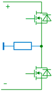
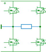
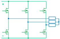
The basic topologies of inverter circuits are similar to those used for rectification (Table 2):
  • midpoint (M) and bridge (B) inverters;
  • single-phase (M/B1,2) and three-phase (M/B3,6) inverters;
  • VSCs, CSCs, and ISCs.
It is noteworthy that, unlike rectifiers, inverters are always built on transistors operated in switch mode, in which they turn on and off the entire load current during the modulation period [55]. Block, six-step, PWM, and space-vector modulation (SVM) techniques have been adopted to control transistors [13].
According to the analysis performed by [66], two-level half-bridge voltage-source inverters (VSIs) are the most widespread converters applied in lightweight robots, thanks to their ease of use along with simple design and control principles. In this topology, only two electronic switches are required, usually MOSFETs or IGBTs, whose control is defined by working frequency and voltage. To act as the HV switches, they are commonly connected in series. The modulation techniques most used in this type of inverter are the sinusoidal PWM, PWM with third harmonic injection, and SVM.
H-bridge VSIs can also be found in lightweight robots [13]. Depending on the control method, this topology can be employed as either the DC/AC or the DC/DC converter. The authors of [67] introduce the H-bridge DC/DC converter used in battery-powered robotic systems. This converter steps down a high DC voltage (400 V) to a lower DC voltage (55 V) suitable for robot actuators.
Other topologies, derived from inverters coupled by diodes and capacitor arrays, allow producing higher voltage levels for heavyweight robots. They are neutral-point-clamped VSIs that deliver three levels of voltage from different DC VSCs or from a single one that is divided with capacitors in series, diode/capacitor clamped inverters with reduced voltage peaks in the switches during commutation, and improved diode-clamped inverters with additional diodes that block voltage spikes. In the flying-capacitor inverters, several capacitors located between the switches isolate the input voltage source. To generate three voltage levels, three capacitors and four switches are placed, while ten capacitors and eight switches make five voltage levels. Therefore, voltage growth is proportional to the number of required devices. A large number of capacitors is the drawback of these topologies, which raises their implementation costs.

4.2. Inverters in Electrical Drives of Robot Mechanisms

A functional diagram of the electrical drive used to feed and control joints, grippers, platforms, vehicle wheels, walking manipulator legs, and other robot mechanisms is shown in Figure 7 [72].
Electrical drive is an electromechanical system that performs adjustable conversion of electrical energy to mechanical energy of the driven mechanism and, often, back. As a rule, AC electrical motors are used to supply separate robot parts from the DC bus via inverters. Among their advantages, the following features are usually listed in the company’s documentation:
  • broad power range, from milliwatts to gigawatts;
  • broad speed range, from units to million revolutions per minute;
  • small vibration and audible noise;
  • little pollution and emissions;
  • reversibility: direction of torque and rotation can be easily changed;
  • controllability: suitability for electronic control;
  • convertibility: the ability of energy regeneration;
Some disadvantages include the following:
  • generation of electromagnetic noise and sparks;
  • a need for appropriate protection against possible shock during exploitation;
  • considering a proper electrical power and supply voltage;
  • some high-power motors have a low power factor, which leads to additional energy loss and cost.
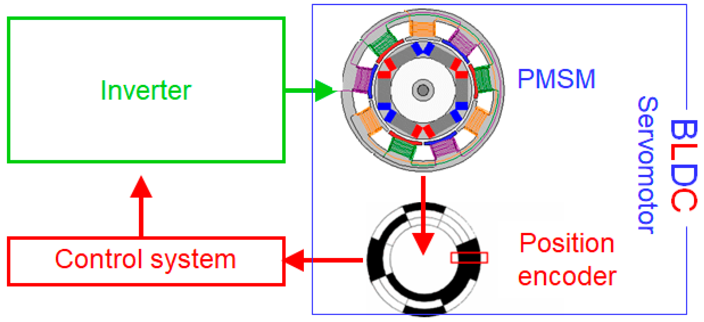
The most frequent solutions are the VSIs that adjust the BLDC motors, composed of a PMSM with a position encoder and an appropriate controller (Figure 8) [44]. In this ensemble, the PMSM behaves much like a DC motor, whose benefits are a broad speed range, small static errors, and highly reliable brushless design with magnets suitable for average-power applications. Among the drawbacks, some authors note the presence of position encoders, high cost, and complexity [68].
One example is from a study [66] where the BLDC electrical drive manages a double-DOF robotic arm, providing their gain scheduling with adaptive fuzzy logic control of the VSI. The three-phase multilevel inverters with 27 voltage levels per phase ensure fast commutation in this system.
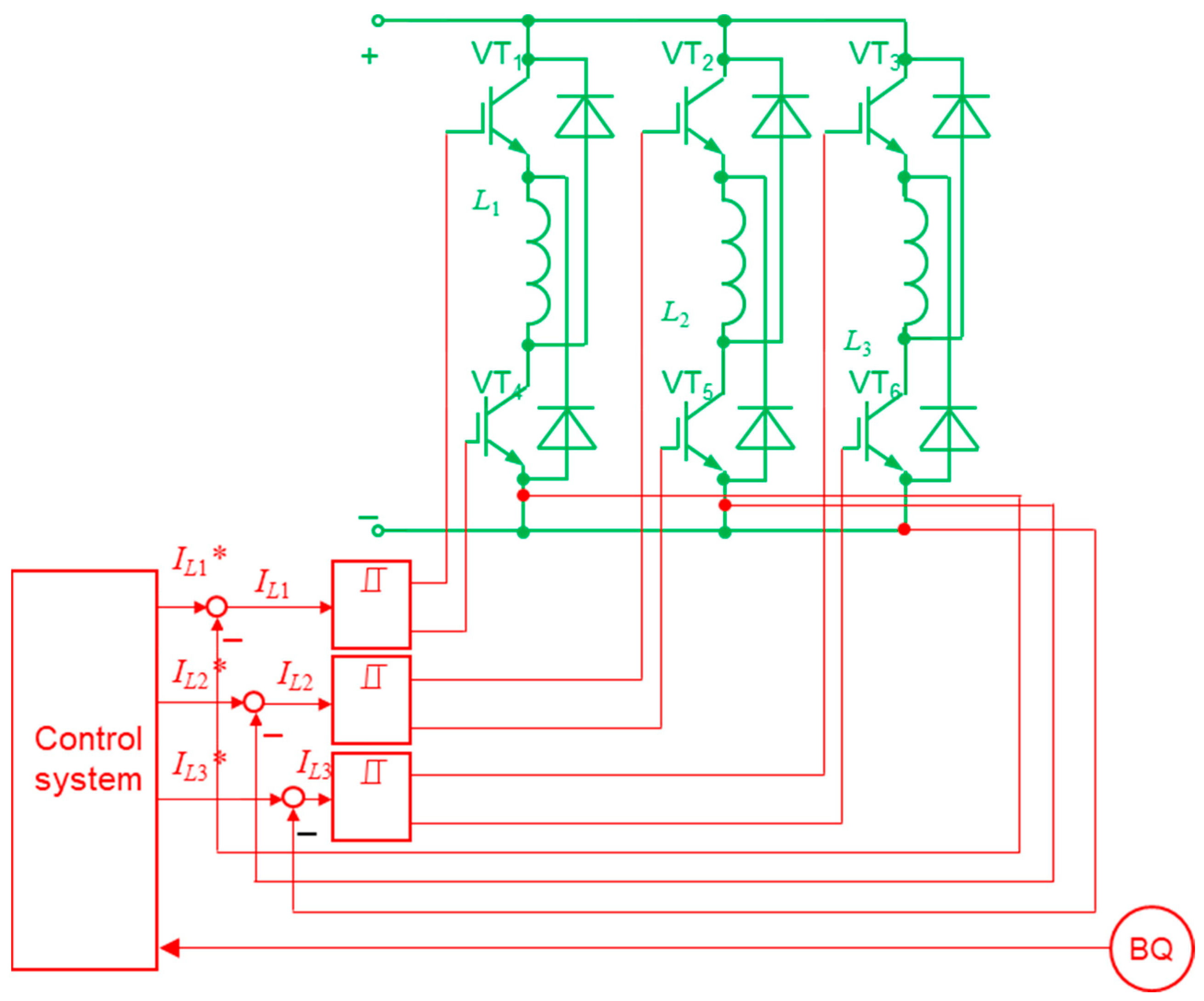
To adjust powerful robot mechanisms, SRM drives are utilised, in which the VSI can be directly built into the motor (Figure 9) [73]. They keep a broad speed range, small static errors, and high reliability along with a gearless and brushless design without permanent magnets and load-independent operation. However, the significant torque ripple, high cost, switching losses, and complex design are the drawbacks of these drives.
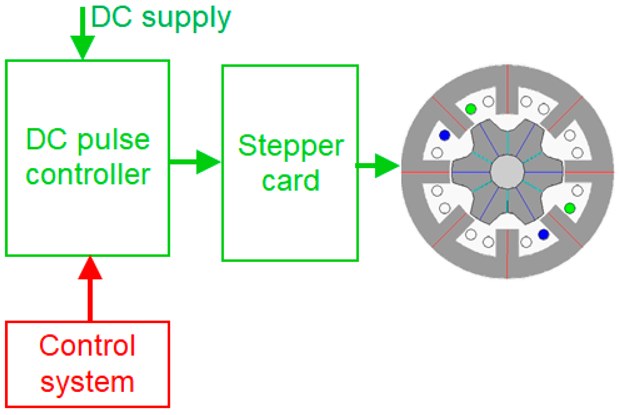
To manage lightweight robotic mechanisms, such as grippers, low-power joints, feeding devices, and conveyors, step drives are applied (Figure 10). For example, in [74], stepper motors manage the 3-DOF robot arm of the production cell. Despite the slow response, sensitivity for inertia, and static torque oscillations that can resonate and result in a loss of position, these drives are in demand when high mechanical and thermal stability is required along with low cost, simplicity, a broad speed range, high reliability, and small energy dissipation in the sensorless, gearless, and brushless design [13].
Current-source inverters (CSIs) are utilised in robotics to drive motors with constant current, offering benefits such as inherent regenerative braking and improved reliability. Nowadays, they are less common in modern robotics due to limitations like slower dynamic response and reduced speed range compared to VSIs. An investigation by Oak Ridge National Laboratory [69] displays the advantages of CSIs in electric vehicle applications, highlighting their potential for reduced inverter cost and volume, increased reliability, and improved motor efficiency. While the focus is on automotive facilities, these features apply to mobile robotics, where regenerative braking and constant-power speed range are advantageous.
However, a CSI is a compelling choice for many other robotic applications, including the following:
  • supplying AC drives with a controlled current waveform that is crucial for precise torque management, smooth speed regulation, and stable operation under varying loads;
  • regenerative braking of robotic systems with frequent start–stop or bidirectional motion for gaining efficiency;
  • raising reliability in harsh environments thanks to CSI robustness against short circuits and overcurrent conditions;
  • direct current control, making it ideal for torque-controlled applications like robotic joints;
  • producing lower EMI compared to VSIs, which is beneficial in sensitive robotic environments.

4.3. Impedance-Source Converters in Robotics

In most inverter operations, the switches are subjected to high stresses and significant power loss that grows linearly along with the switching frequency [55]. To realise fast operations under such circumstances, it is better to perform switching when the voltage across the switch and/or current through it at the time of switching is as low as possible, including zero.
ISCs are increasingly recognised in robotics for their ability to manage power efficiently, particularly in applications with unstable energy supply and regenerative braking. These converters are designed to handle both step-up and step-down voltage transformation, offering enhanced flexibility and reliability of robotic power and control systems [75,76].
Power sources called Z-source inverters (ZSIs) represent the class of ISCs with a network comprising inductors and capacitors to efficiently convert DC to AC. This topology allows for both buck and boost operations without the need for a separate DC/DC block. Thanks to their ability to handle wide input voltage variations and provide higher reliability compared to traditional inverters, ZSIs look promising for robots to enhance efficiency, reduce component numbers, and enable regenerative braking. However, while ZSIs are not yet commonplace in mainstream robotics, their application in electric vehicles and industrial motor drives showcases their potential benefits for robots requiring efficient and compact power conversion. As an example, in [48], ZSIs have been applied in fuel cell–battery hybrid electric vehicles. They enable simultaneous control of the fuel cell power, output power to the motor, and the state of charge of the battery. This integration is important for mobile robotics as it simplifies the system and reduces onboard cost and complexity.
To minimise switching and conduction losses and EMI, the ZVS and ZCS techniques are presented in all inverter types: VSIs, CSIs, and ZSIs.
In [70], ZCS/ZVS bidirectional converters designed for energy storage systems utilising soft-switching techniques are demonstrated. Implementation of ZCS during boost mode and ZVS during buck mode operations reduces switching losses, thereby contributing to the robot’s effective performance in the study.
In [71], an interleaved ZCS-supplied switching PEC has been proposed for fuel cell-based propulsion systems. This converter reduces input current ripple and minimises the size of passive components, which is advantageous for mobile robots and electric vehicles.
In their study, the authors of [77] introduce a single-output ZVS push–pull converter designed for robotic stations delivering 5 V at 1 A to a servo drive operated at a switching frequency of 50 kHz.
Thus, the ZSIs are gaining traction in mobile and renewable-powered robots due to their unique advantages in power conversion. Their most intensive development is observed and expected in the future in the following scenarios:
  • among the solar-powered robots, where ZSIs can efficiently convert the variable DC output from solar panels to a stable AC supply, ensuring consistent performance of the robot;
  • among battery-powered robots, where ZSIs can manage the varying voltage levels from the battery, providing a stable power supply to the robot’s components;
  • among hybrid systems that use a combination of renewable energy sources and batteries, where ZSIs can seamlessly integrate and manage power from multiple sources.
These advancements and trends are making ZSIs even more suitable for complex and demanding applications in robotics.

5. Present State, Development Trends, and Advancements of AC/AC Converters Used in Robotics

5.1. DC-Link Converters to Supply AC Loads

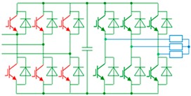
The main AC consumers of robots are the adjustable motors of joints and grippers, the speed, torque, and position of which are subject to control. Stationary robots are usually supplied from AC grids. Mobile robots are additionally equipped with charging systems, the windings of which are also AC consumers. Their regulation is carried out using AC/AC converters of various topologies, presented in Table 3, where additional energy flow channels are shown in red.
Most stationary robots are connected to the AC grid via AC/AC DC-link converters with front-end diode rectifiers, a big capacitor filter in the DC bus, and back-end inverters feeding the driven motors.
In self-driving vehicles, speed-controlled squirrel-cage induction motors are often installed. In [78], the DC-link converters that feed such motors are automatically managed by the adaptive proportional-integral-derivative (PID) controller when the robot payload changes.
In [82], a DC-link SVM-modulated drive with an IRC5-controller employs a constant torque-angle control strategy to achieve maximum torque. In this system, the AC PMSM behaves like a DC machine, in which the torque-producing component is adjusted by adding three stator currents as the space-vectors multiplied by 2/3.
One of the techniques adopted for reducing the energy expenditure of robotic systems is the addition of energy-storing and recovering devices. The main idea behind these devices is to harvest the energy wasted during the braking phase, store it, and return it to the system when necessary. In industry, brake choppers with brake resistors are utilised to dissipate the recuperated energy; however, this solution is more suitable for heavyweight robots due to high procurement costs and great losses in the brake resistor at motor deceleration.
In [4], the kinetic energy recovery systems (KERS) are analysed that allow energy to be stored for further usage when needed. Quite popular are mechanical KERSs (e.g., flywheels), electrical KERS (e.g., chemical batteries, capacitors, and supercapacitors), hydraulic KERS (e.g., hydro-pneumatic accumulators), and hydro-electrical KERS (e.g., hydraulic motors coupled with electrical generators). In [88], based on a KERS comparison, flywheels were offered as the best devices in terms of voltage stability, temperature range and efficiency. A flywheel-based energy-storage system is fully compatible with heavy manipulators, and it can achieve a reduction in power consumption. In the 3-DOF rubber-tired gantry crane with PMSM-fed joints, an integrated flywheel spinning at high speed perfectly met the peak energy requirements of the robot during both acceleration and regenerative braking. This KERS has high energy density and a virtually infinite number of charge–discharge cycles, where batteries and supercapacitors are not capable. To ensure very high peak power with significant power density and suitable charging/discharging cycles of the flywheel, the PMSM operates as a motor that generates a positive torque. Similarly, at a negative torque, the PMSM acts as a generator when discharging the flywheel.

5.2. AC/AC Converters with Shared DC Bus

Energy sharing is another approach to reducing energy losses in robotic systems. The working principle of energy-sharing devices is based on the distribution of braking motor energy over a common DC bus for feeding other (non-braking) motors. Today, some commercial robots allow sharing the recuperating energy when one joint decelerates and others accelerate [23,82].
In particular, the shared DC-link system in [80] comprises an energy source, a common AC/DC module, and a set of DC/AC modules feeding the appropriate geared motors.
The solution proposed in [79] enables an exchange of recuperated energy within the independent DC bus with one centralised energy storage element. This approach allows the elimination of the brake resistor with the external storage of wasted energy. Herein, identical hardware or exact synchronisation between the drive rectifiers is not needed.
However, when several axes break simultaneously, the available energy volume may exceed the installed DC-link capacitance. The source of this overvoltage lies not only in the decelerating motor but also in static loads such as open mechanical brakes, self-consumption of motor drives, control systems, cooling fans, communication electronics, and other consumers that spend together additional power during the movement phase, and even in standby mode, when the brakes are released and the drives are off.
To resolve this issue in industrial robots KUKA KR200 and KR210 with one rectifier supplying six inverters, an additional brake chopper is offered in [81], which switches on two parallel-connected balancing resistors. This chopper is activated at 688 V, while the DC-link voltage usually ranges from approximately 490 V to 690 V.
Nevertheless, all the above-described DC-link converters with a diode front end have the following common disadvantages [69,72]:
  • the DC bus slows down converter dynamics; therefore, the drives slowly respond at frequent starting, braking, and current direction changes;
  • the DC bus voltage cannot be adjusted, as its level depends only on the supply voltage and the front-end topology;
  • due to the diodes, the AC line current waveform is non-sinusoidal, hence the high level of EMI penetrates to other equipment and disturbs their normal operation;
  • current distortion evokes a distortion of the voltage and can affect the performance of other consumers connected to the power supply system.

5.3. Advanced AC/AC Converters for Robotics

Including a front-end active rectifier between the supply grid and the DC bus provides the solution for most of the above problems in ABB, FANUC, KAWASAKI, and many other robots [83,89]. The drives with active rectifiers are capable of four-quadrant operation and, consequently, recuperating electrical energy from the mechanical motion during deceleration phases. In the motoring mode, when the drive acquires supply power, the front end carries the current through the diodes, while the back-end inverter passes the current through the transistors. When the DC bus voltage exceeds some dangerous level, for example, at braking, the back-end stage turns into the rectifier mode, passing the current through the freewheeling diodes, and the front-end stage serves as an inverter and carries the current through transistors [31].
For example, power supply modules of FANUC robots are engineered to support regenerative power source capabilities, allowing for the efficient return of energy during deceleration phases [84]. This regenerative feature contributes to energy savings and reduces operational costs.
The high-speed palletising KAWASAKI robots of the CP Series are also equipped with regenerative controllers that allow energy to return during deceleration phases, effectively reducing overall power consumption by up to 40% compared to models without the ability to recover [24]. This feature is particularly beneficial for consumers requiring high-speed and high-load capacities.
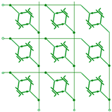
A much more effective approach is to introduce direct converters, such as AC/AC matrix converters, representing PECs built on four-quadrant switches that turn AC to AC without any intermediate DC buses. They are valued for their compactness, bidirectional power flow, and sinusoidal input/output waveforms [35,36,85]. In robotics, matrix converters are not very widespread yet. Nevertheless, ongoing advancements in semiconductor technology are improving the efficiency and reliability of matrix converters. This is making them more attractive for use in high-performance robotic applications, where they are set to play a significant role in the future, enhancing efficiency, control, and integration with renewable energy systems. According to [35,36], shortly these converters will facilitate fine-tuned control and efficient power management, which is crucial for precise robotic movements. As long as matrix converters are being integrated with advanced power management systems, this ensures that robotic components receive precise voltage levels, leading to improved motor performance and extended operational times. With the growing emphasis on renewable energy, matrix converters will be used even in robots powered by renewable sources, ensuring the stable operation of the robotic systems. In autonomous robots, they promise efficient power conversion and precise control of motors and actuators. In industrial settings, they will be even more employed for tasks like handling, assembly, and welding, where precise control and efficiency are paramount. Robots powered by renewable energy sources will benefit from the efficient power management capabilities of matrix converters.
Already at the present time they are used in certain high-performance or research-based robotic systems, especially where size, small losses, and advanced control are critical.
In particular, the use of matrix converters in onboard deep-sea autonomous vehicles is reported in [86]. They provide sustainable operation at high ambient pressures up to 300 bar at a depth of 3000 m, thus minimising the number of external connections and cabling mass, improving reliability and reducing drag. Emphasis is given to 32 matrix converters for 3-phase to 1-phase AC voltage/frequency conversion in auxiliary drives, and the application of 33 matrix converters for handling the PMSM-based actuators.
The Matrix Robot Arm Production Cell V2 by Buckeye Educational Systems represents an example of an educational robotic arm fed by matrix converters. This system is designed for teaching purposes to provide hands-on experience in robot control and programming [74].
The Digital I/O Converter Kit by ONROBOT facilitates the integration of various end effectors with a wide range of manipulators, including KUKA, FANUC, YASKAWA, KAWASAKI, DOOSAN, NACHI, and TECHMAN. Matrix converters in these solutions demonstrate their ability to manage power and signals [87].

6. Present State, Development Trends, and Advancements of DC/DC Converters Used in Robotics

6.1. Classical DC/DC Converters in Robotics

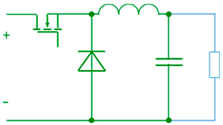
DC/DC converters are incredibly common in robotics; almost every robot contains them in onboard electronic modules. They align and adjust voltage levels between energy sources (like batteries), power sources (like fuel cells), and subsystems (like sensors, actuators, microcontrollers, or motor drivers). Table 4 demonstrates how and where DC/DC converters are used across various types of robots.
DC/DC converters perform the following functions:
  • setting the DC voltage feeding motor drives before further inverting with adjustment of supply amplitude, phase, or frequency;
  • preventing electromagnetic noise and protecting control boards from voltage dips, surges, or short circuits;
  • powering control electronics of manipulator arms, sensors, cameras, communication modules, and thrusters from centralised suppliers;
  • reducing battery voltages (typically 24 V/48 V, 14.8 V, or 22.2 V) to 5 V or 3.3 V levels for cameras, sensors, microcontrollers, orientation equipment, etc.;
  • handling voltage rails across navigation and driving subsystems.
Buck converters are adopted in nearly all battery-powered robots, from simple Arduino bots to advanced mobile robots, including humanoids, flying, floating, and walking robots.
In hybrid DC storage units, shown in Figure 2, buck converters link supercapacitors and flywheels to batteries and fuel cells [12]. For example, in [62], the unidirectional DC/DC converter connects the fuel cell to the 24 V DC bus, whose power varies along with the change of the load current. In [54], for the sake of simplicity, fixed-ratio converters successfully scale up or down the voltage of sources, thus enhancing their dynamic response capabilities or adapting them to an HV source. These converters provide a low-impedance path, allowing loads such as motor drives to draw current quickly without response delay or voltage slump in long cables.
Many industrial robots are powered by higher DC voltages than required, and buck converters feed their embedded controllers, sensors, encoders, and networking hardware. For instance, the LM2596 buck converter operates at input voltages ranging from 4.5 to 40 V, ensuring the output adjustable voltages are between 1.25 and 35 V at the load current up to 3 A [90]. This makes it suitable for powering various robotic subsystems, including microcontrollers, sensors, and communication modules. Its high efficiency (up to 92%), built-in short-circuit, and over-temperature protection enhances the reliability of commercial robots such as CLEARPATH HUSKY UGV, BOSTON DYNAMICS SPOT, and DJI drones.
In [65], heavy self-driving vehicles are charged from the HV DC grids, from 40 to 800 V. The VICOR BCM fixed-ratio converter series reduces these voltages to safe 10–48 V levels at 97% efficiency
FANUC robots, particularly those utilising the Alpha i-series and Beta i-series amplifiers, incorporate DC/DC converters within their power supply modules [22]. For instance, the αiPS power supply module stabilises the DC-link voltage, ensuring consistent performance across the system. This device was designed for easy maintenance, allowing for quick replacement of components like circuit boards and fans without disassembling the entire unit.
Boost converters are usually presented in robotic applications with a PV supply [12] because PV sources generate relatively little energy, and the output of the PV panel depends on multiple factors, such as temperature, irradiation, dirt deposition, battery type, charge profile, etc. For example, the boost DC/DC converter is used in [92] to feed the solenoid for a RoboCup shooting device. Also, boost converters are often applied for power factor correction, mainly because of their simple topology, smart design, and compatibility for a universal AC input voltage range [93].
Buck-boost converters are employed in various robotic stations to manage energy efficiently, especially when dealing with variable input voltages. In particular, they are adopted for hybrid energy storage devices of e-vehicles with two different operation modes, namely the charging and the discharging mode [12]. In discharging mode, energy is transferred from the battery and/or supercapacitor to consumers. On the other hand, in charging mode, deposited energy is transferred from consumers to the supercapacitor and the battery.
For example, buck-boost converters reported in [94] are applied to power servo drives of quite sophisticated multi-DOF manipulators. The ROBOTSHOP Company [91] offers a buck-boost module with an input range of 3.8 to 32 V and an output range of 1.25 to 35 V for facilities requiring voltage regulation from solar panels and generators of autonomous robots operating in outdoor environments. In [54], buck and buck-boost converters act at a wide input voltage range in power delivery networks up to 75 V, allowing the LV power conversion stages to adapt to higher or lower battery voltages of various platforms.
The ZVS is a widespread mode of operation in many DC/DC PECs.
For example, the buck and buck-boost PECs designed by VICOR for mobile robots act in the ZVS mode [15]. They have a 97% efficiency rating and deliver 200 to 300 W of power in either the buck or the boost modes, depending on the battery state of charge. In this way, they provide a consistent supply on the specific power rails at high power density and low heating.
In [99], a DC/DC converter employing both ZVS and ZCS techniques is presented. This converter combines the buck-boost operation with soft-switching capabilities, thus enhancing efficiency and reducing switching losses.
Research from Okayama University [100] explores a DC/DC converter for supercapacitor-based energy storage systems of automotive applications, like mobile robots. The converter employs ZVS to reduce switching losses and utilises synchronous rectification to minimise conduction losses of the energy storage system.

6.2. Bidirectional DC/DC Converters for Robot Supply

Bidirectional DC/DC converters unite buck and boost abilities in a uniform device [101].
One such converter was developed in [96] to reduce robot size and weight, along with the power factor improvement. This PEC is composed of 10 switching cells, each made of one capacitor to store the energy and two complementary switching MOSFETs for voltage balancing. This design and realisation are very suitable for robotic cells since it can be made small, modular, and portable.
In [62,97], a bidirectional DC/DC converter realises effective power regulation of a battery module. When the battery is charged, the converter operates in the step-down mode, while when the battery is discharged, the PEC acts in the step-up mode.
In [102], the authors discuss various bidirectional DC/DC converters given their possible realisations with challenges in the distribution functions among DC and AC rails. An important advantage of bidirectional converters relates to their ability to utilise the same semiconductor switches and passive components in the DC/AC and DC/DC topologies to maximise their effectiveness in both modes.
In [9,44], the studies describe hybrid storage units composed of a battery, supercapacitors, and fuel cells. To manage DC/DC converters, an optimal power distribution strategy is proposed here. In [14], a similar approach is applied for a 600 W self-humidifying fuel cell mounted on a welding robot. Bidirectional DC/DC converters were deployed in this research to manage the energy flow, namely to charge batteries during idling and braking and to supplement power during motion.
In [98], a hybrid system of solar panels and batteries is offered, aiming to handle power robots. The proposed DC/DC PEC integrates a bidirectional converter, which allows the batteries to be charged from solar panels, a wall outlet, and a deployable solar charging station.
Different kinds of indirect isolated DC/DC converters can be found in the literature.
In sensor and communication equipment of robots, the low-power (100–200 W) flyback converters represent a transformer-based version of buck-boost PECs [95]. This simple power supply topology provides voltage stepping up or down with electrical isolation between the input and output. It provides various output voltages from a single input using one switch and one magnetic element, the transformer, through which energy is transferred during the off-time of the primary circuit.
VICOR [54] also offers high-performance isolated DC/DC converters tailored for robotics. Their DCM series has adjustable isolated outputs at high power density for compact systems. These converters provide bidirectional stepping up of the battery voltage for higher-voltage batteries and/or transmission lines. They allow for regenerating braking energy into the battery or the DC bus. The authors explore how to parallel such converters using a voltage-droop-share method and the impedance of branches. In [7], the integration of isolated DC/DC converters in diverse robotic stations is also reviewed.
TEXAS INSTRUMENTS [103] provides reference designs for isolated DC/DC converters suitable for low-power robot devices. For instance, their TIDA-00689 devices represent compact, low-profile PECs ideal for space-constrained robotic modules.
A similar solution is described in [64], which operates in the 2 to 3 kW power range with 92–95% efficiency. The return/ground for the LV side is normally connected to the vehicle chassis, providing galvanic isolation between the LV and HV rails for safety and for protecting the LV controller. Isolation between the HV input and LV output of a converter is accomplished via a transformer. Switching frequencies can be relatively high (e.g., 100 kHz) to keep the minimal transformer size. The HV switches are implemented on IGBTs, whereas in the latest solutions, the SiC-MOSFETs are used to increase power density and reduce the size.
The 36 V or 48 V batteries are connected to the motor drives via the transformer-isolated DC/DC converters in [104]. Their low-weighted small core and copper wires provide maximal (up to 98.5%) efficiency in warehousing, inspection, disinfecting, security, and vacuum cleaner robotic applications. This design reduces heat loss and simplifies cooling, making the converter smaller and cheaper and accepting various DC input levels with a wide output adjustment range.
Another improved full-bridge PWM converter is offered in [55] for robot battery charging. Thanks to the ZVS characteristics of its isolated H-bridge converter, the switching and conduction losses decreased, and the PEC efficiency was significantly improved compared to the traditional hard-switching H-bridge converters. To reduce the size of magnetic components, the switching frequency was set to 100 kHz in this design.

6.3. Wireless Power Transfer in Robotics

Wireless power transfer (WPT) is becoming increasingly important in robotics, especially for direct powering of mobile devices, when energy is transferred directly to the load without storage, and for wireless charging, when energy is stored in a battery and/or supercapacitor after being received [105].
One possible application relates to establishing WPT to a robotic arm made of a ferromagnetic composite. In the traditional manipulator, where a power cable is used to transfer power from the upper arm to the lower arm, the frequent bending actions of the elbow joint unfavourably affect the system’s reliability. In [105], the WPT is arranged to supply the robotic arm instead of the cable. Despite low efficiency (26–30%), this design brings many benefits. The first one is the flexibility of relative orientation between the power source and device during the operation, making the system simpler and more convenient for application. Also, several loads can be powered up using a single source, even when the devices have different power requirements. Resonators of various sizes can be used here, suitable for operation even at a weak coupling rate. Additionally, the power transmission distance may be increased significantly using magnetic repeaters that enable energy to “hop” between them.
Now, many household robots are charged by cables, bringing such disadvantages as big battery dimensions, short cruising range, and long charging time [15]. Cable charging greatly limits the charging position of the logistic robots, which are often unable to meet the characteristics of fully automated processes. As a solution to this problem, a WPT technology is introduced into home and office robots [106]. For example, a wireless power supply system encapsulated into a household robot is described in [107]. Its front-end inverter converts a DC voltage into a high-frequency AC voltage, applying it to the resonance circuit, which, in turn, transfers energy to the receiver with the back-end rectifier supplying the DC load.
Multi-output DC/DC converters of CALEX [108] provide WPT from the Li-ion battery to the onboard electronics in delivery, industrial, and special-task robots, as well as drones, robotic taxis, forklifts, agricultural harvesting manipulators, disinfecting, logistic, and collaborative robots, as well as the micro and mild hybrid automotive systems. The advantages of CALEX converters are numerous. They ensure one of the highest power densities in industry for power ranges from 50 to 3000 W, an ultra-thin small-size profile, efficiency up to 95.5%, an operating temperature range of −40 to +100 °C, light weight, and ruggedized design.
A battery-less mobile robot in [9] is mounted on a long rail. It acts under the dynamic WPT with a synchronous buck converter acting as a CSC. The system cost was reduced, thanks to the coreless connection of the primary and secondary 32 W coils.
WPT with resonant circuits is also used to charge e-vehicles in motion, more commonly known as dynamic charging. In [109], four resonant circuit topologies are compared from the point of view of their usage in charging systems. They are named according to the method of inserting the resonant capacitors on each side: series–series, series–parallel, parallel–series, and parallel–parallel. The specific topology of a wireless charging system suitable for both DC and AC supply is also proposed in this study.
In [110,111,112], WPT is implemented as a magnetically coupled, resonance-based wireless charging of a mobile robot. This method has a wider transmission range compared with an electromagnetic coupling due to the resonance effect in both transmitter and receiver circuits. The DC/DC converter is set here between the battery and the inverter to compensate for inductance instability that affects the transmission losses. Herein, the power is adjusted to the level at which the constant charging current is supported.
Another contactless power charger for robots is described in [92], where a two-phase constant-current/constant-voltage (CC/CV) charging scheme is adopted for the buck stage at the robot side to prolong the battery lifetime. When the battery voltage is low, the buck charger is operated at CC mode to keep a constant current. When the battery voltage reaches a preset value, the buck charger is operated at CV mode, and the charging current rapidly drops with an exponential profile to prevent overcharging. This charger supports the well-regulated output despite the load and gap variations. The overall efficiency reached 60%, and the input power factor was above 0.96.
In [51,52], a high-frequency GaN-based capacitive WPT system for mobile robots is presented. Unlike many conventional WPT systems, the developed module allows in-motion charging by going underneath the charging pads attached to the bottom of a low-lying surface, thereby minimising the risk of human exposure to high fringing fields. The proposed system can be automatically turned on and off by detecting the robot’s proximity using an infrared-based sensing technique on the 12 cm air-gap prototype. An inverter on the primary side converts the DC input voltage to a high-frequency AC voltage, which is stepped up by a primary network and transferred through the air gap. The displacement current is then changed to the required output level through the half-bridge rectifiers designed to enable this charging system to maintain full power transfer even for large misalignments in the coupler.
Based on the literature analysis, it can be assumed that the following main trends in the development of WPT in robotics are expected in the coming years:
  • design of dynamic WPT will eliminate downtime and enable 24/7 operation in logistics and manufacturing;
  • integration of AI to power management will provide smarter energy allocation, reduced power waste, and extended battery life of autonomous robots;
  • far-field WPT (radio frequency, microwave, laser) will improve untethered operation of aerial drones, underwater robots, and space robots in remote or hazardous environments;
  • development of universal WPT standards will simplify integration across different robot types and manufacturers, promoting plug-and-play ecosystems;
  • combining WPT with energy harvesting (solar, kinetic, thermal) and supercapacitors will increase energy autonomy and reduce reliance on large batteries, especially in micro-robots and wearables;
  • advanced shielding, beamforming, and frequency control will ensure safe and interference-free operation, making WPT viable in environments with sensitive electronics or human presence (e.g., hospitals, homes);
  • proper resonant inductive coupling will enable efficient mid-range wireless charging for mobile robots and drones, even while in motion or during idle periods;
  • swarm and cooperative charging will enhance energy resilience in robotic swarms and distributed systems.

7. Conclusions

Designers, researchers, and engineering staff face several hands-on challenges during robot powering. To resolve them, this work provides an up-to-date summary of PECs used for robot supply, their classification, and solutions adopted to integrate advanced power electronics into robotics. After studying numerous online resources and company databases where commercial and experimental results are presented, the comparative power-frequency characteristics of Si, SiC, and GaN semiconductors used in robotic PECs are derived in this research. The literature review opens at least two directions that PEC manufacturers choose nowadays and should employ in the future to achieve higher efficiency and a faster conversion rate. The first method relates to implementing WBG devices that exceed Si-based electronics. The second trend in improving energy conversion is to incorporate advanced PEC topologies. They are shared DC-link circuits, active and synchronous rectifiers, various ISCs with ZVS and ZCS, direct (matrix) AC/AC converters, indirect isolated networks, and wireless charging systems, including their multi-output and dynamic in-motion charging representatives. The review opens broad prospects of PEC design, aimed at reducing robot masses, increasing compactness, and promoting efficiency growth.

Author Contributions

Conceptualization, methodology, and investigation, V.V.; data curation and writing, Z.R. All authors have read and agreed to the published version of the manuscript.

Funding

This research received no external funding.

Data Availability Statement

The original contributions presented in the study are included in the article; further inquiries can be directed to the corresponding author.

Conflicts of Interest

The authors declare no conflicts of interest.

Abbreviations

The following abbreviations are used in this manuscript:
3Dthree-dimensional
AIartificial intelligence
ACalternating current
BJTbipolar junction transistor
BLDCbrushless DC
CCconstant current
CMOScomplementary MOS
CSCcurrent-source converter
CSIcurrent-source inverter
CVconstant voltage
DCdirect current
DMOSdouble-diffused MOS
DOFdegree of freedom
EMIelectromagnetic interference
ESenergy source
FETfield-effect transistor
GaNgallium nitride
GTOgate turn-off
HEMThigh electron mobility transistor
HVhigh voltage
IGBTinsulated-gate bipolar transistor
IGCTintegrated gate commutated thyristor
ISCimpedance-source converter
KERSkinetic energy recovery system
LVlow voltage
MOSmetal-oxide semiconductor
MOSFETmetal-oxide semiconductor field-effect transistor
PECpower electronic converter
PIDproportional-integral-derivative
PMSMpermanent magnet synchronous motor
PSpower source
PVphotovoltaic
PWMpulse-width modulation
RMSroot mean square
SCRsilicon controlled rectifier
Sisilicon
SiCsilicon carbide
SJ-FETsuper-junction FET
SRMswitch-reluctance motor
SVMspace-vector modulation
VSCvoltage-source converter
VSIvoltage-source inverter
WBGwide bandgap
WPTwireless power transfer
ZCSzero current switching
ZSIZ-source inverter
ZVSzero voltage switching

References

  1. Energy Technology Perspectives 2024; IEA: Paris, France, 2024; 574p, Available online: https://www.iea.org/reports/energy-technology-perspectives-2024 (accessed on 15 April 2025).
  2. World Energy Outlook 2023; IEA: Paris, France, 2024; 398p, Available online: https://www.iea.org/reports/world-energy-outlook-2024 (accessed on 15 April 2025).
  3. World Robotics 2024 Report by International Federation of Robotics. Available online: https://robotsguide.com/ (accessed on 15 April 2025).
  4. Carabin, G.; Wehrle, E.; Vidoni, R. A Review on energy-saving optimization methods for robotic and automatic systems. Robotics 2017, 6, 39. [Google Scholar] [CrossRef]
  5. Babu, T.S.; Vasudevan, K.R.; Ramachandaramurthy, V.K.; Sani, S.B.; Chemud, S.; Lajim, R.M. A comprehensive review of hybrid energy storage systems: Converter topologies, control strategies and future prospects. IEEE Access 2020, 8, 148702–148721. [Google Scholar] [CrossRef]
  6. Trabelsi, M.; Vahedi, H.; Abu-Rub, H. Review on single-dc-source multilevel inverters: Topologies, challenges, industrial applications, and recommendations. IEEE Open J. Ind. Electron. Soc. 2021, 2, 112–127. [Google Scholar] [CrossRef]
  7. Singh, R.; Kurukuru, V.S.B.; Khan, M.A. Advanced power converters and learning in diverse robotic innovation: A review. Energies 2023, 16, 7156. [Google Scholar] [CrossRef]
  8. Mikołajczyk, T.; Mikołajewski, D.; Kłodowski, A.; Łukaszewicz, A.; Mikołajewska, E.; Paczkowski, T.; Macko, M.; Skornia, M. Energy sources of mobile robot power systems: A systematic review and comparison of efficiency. Appl. Sci. 2023, 13, 7547. [Google Scholar] [CrossRef]
  9. Farooq, M.U.; Eizad, A.; Bae, H.-K. Power solutions for autonomous mobile robots: A survey. Robot. Auton. Syst. 2023, 159, 104285. [Google Scholar] [CrossRef]
  10. Flores-Bahamonde, F.; Renaudineau, H.; Llor, A.M.; Chub, A.; Kouro, S. The dc transformer power electronic building block: Powering next-generation converter design. IEEE Ind. Electron. Mag. 2023, 17, 21–35. [Google Scholar] [CrossRef]
  11. Deng, F.; Hou, J.; Zhang, Y.; Cheng, M.; Hu, Y.; Vazquez, S. A furtherance of high-power adjustable-speed drive systems: Medium-frequency ac link-powered machine drive systems. IEEE Ind. Electron. Mag. 2023, 17, 17–31. [Google Scholar] [CrossRef]
  12. Lee, M.-F.R.; Nugroho, A.; Bahrudin, A. Energy management system for sustainable operation of robot in disaster response. In Proceedings of the 2020 International Conference on Sustainable Energy Engineering and Application (ICSEEA), Tangerang, Indonesia, 18–20 November 2020; pp. 22–29. [Google Scholar] [CrossRef]
  13. McComb, G. Robot Builder’s Bonanza, 5th ed.; McGraw-Hill: New York, NY, USA, 2018; 704p, Available online: https://www.amazon.com/Robot-Builders-Bonanza-Gordon-McComb-dp-1260135012/dp/1260135012/ref=dp_ob_title_bk (accessed on 15 April 2025).
  14. Mohseni, P.; Husev, O.; Vinnikov, D.; Strzelecki, R.; Romero-Cadaval, E.; Tokarski, I. Battery technologies in electric vehicles: Improvements in electric battery packs. IEEE Ind. Electron. Mag. 2023, 17, 55–65. [Google Scholar] [CrossRef]
  15. Emilio, M.D.P. Power Converters Enable Innovation in Robotics Applications. 2023. Available online: https://www.powerelectronicsnews.com/ (accessed on 15 April 2025).
  16. Verstraten, T.; Hosen, M.S.; Berecibar, M.; Vanderborght, B. Selecting suitable battery technologies for untethered robot. Energies 2023, 16, 4904. [Google Scholar] [CrossRef]
  17. Hussain, A. Revolutionizing Robotics. 2024. Available online: https://www.nxp.com/company/blog/revolutionizing-robotics-advancements-in-edge-processing-power-sensors-and-communication:BL-REVOLUTIONIZING-ROBOTICS (accessed on 15 April 2025).
  18. Raud, Z.; Vodovozov, V. Power Electronics: Electrical Energy Converters; LAP Lambert Academic Publishing: Saarbrücken, Germany, 2014; 132p. [Google Scholar]
  19. De Silva, D.; Sierla, S.; Alahakoon, D.; Osipov, E.; Yu, X.; Vyatkin, V. Toward intelligent industrial informatics: A review of current developments and future directions of artificial intelligence in industrial applications. IEEE Ind. Electron. Mag. 2020, 14, 57–72. [Google Scholar] [CrossRef]
  20. Singh, R.; Paniyil, P.; Zhang, Z. Transformative role of power electronics: In solving climate emergency. IEEE Power Electron. Mag. 2022, 9, 39–47. [Google Scholar] [CrossRef]
  21. Huber, J.; Imperiali, L.; Menzi, D.; Musil, F.; Kolar, J.W. Energy Efficiency is Not Enough! IEEE Power Electron. Mag. 2024, 11, 18–31. [Google Scholar] [CrossRef]
  22. Drive Systems Product Overview; FANUC Europe Corporation: Luxembourg, 2023; Available online: https://pdf.directindustry.com/pdf/fanuc-europe-corporation/drive-system/32007-1043899.html (accessed on 15 April 2025).
  23. KR FORTEC Ultra; KUKA: Augsburg, Germany, 2025; Available online: https://www.kuka.com/en-de/products/robot-systems/industrial-robots/kr-fortec-ultra-heavy-duty-robot (accessed on 15 April 2025).
  24. General Purpose Robots (350–1500 kg Payload); Kawasaki Robotics: Wixom, MI, USA, 2025; Available online: https://kawasakirobotics.com/robots-category/extra-large-payloads/ (accessed on 15 April 2025).
  25. Heredia, J.; Kirschner, R.J.; Schlette, C.; Abdolshah, S.; Haddadin, S.; Kjægaard, M.B. ECDP: Energy consumption disaggregation pipeline for energy optimization in lightweight robots. IEEE Robot. Autom. Lett. 2023, 8, 6107–6114. [Google Scholar] [CrossRef]
  26. DLR Light Weight Robot III (LWR III); Institute of Robotics and Mechatronics, German Aerospace Center (DLR): Cologne, Germany, 2025; Available online: https://www.dlr.de/en/rm/research/robotic-systems/arms/lwr-iii (accessed on 15 April 2025).
  27. Zewe, A. Hopping Gives This Tiny Robot a Leg Up; MIT News: Cambridge, MA, USA, 2025; Available online: https://news.mit.edu/2025/hopping-gives-tiny-robot-leg-up-0409 (accessed on 15 April 2025).
  28. Fang, H.; Guo, L.; Bai, S. A light weight arm designed with modular joints. In Recent Advances in Mechanism Design for Robotics; Mechanisms and Machine Science; Bai, S., Ceccarelli, M., Eds.; Springer: Cham, Switzerland, 2015; Volume 33. [Google Scholar] [CrossRef]
  29. Kim, T.; Kwak, S.; Park, J.-D. Hybrid system control for robot motors based on a reduced component, multi-voltage power supply system. IEEE Trans. Circuits Syst. II Express Briefs 2021, 68, 3582–3586. [Google Scholar] [CrossRef]
  30. Industrial and Collaborative Robots; Advanced Energy: Denver, CO, USA, 2024; Available online: https://www.advancedenergy.com/en-us/applications/industrial/transport-robotics/industrial-and-collaborative-robots/ (accessed on 15 April 2025).
  31. Hansen, C.; Eggers, K.; Kotlarski, J.; Ortmaier, T. Task specific trajectory profile selection for energy efficient servo drive movements. In Proceedings of the 31st International Symposium on Automation and Robotics in Construction and Mining, Sydney, Australia, 9–11 July 2014; pp. 514–522. [Google Scholar] [CrossRef]
  32. Paul, S.; Lee, D.; Kim, K.; Chang, J. Nonlinear modeling and performance testing of high-power electromagnetic energy harvesting system for self-powering transmission line vibration deicing robot. Mech. Syst. Signal Process. 2021, 151, 107369. [Google Scholar] [CrossRef]
  33. Meng, F.; Wang, C.; Liu, Z.; Ma, K.; Disney, D.; Yeo, K.S. Heterogeneous integration: A promising technology to future integrated power conversion electronics. IEEE Power Electron. Mag. 2021, 8, 37–47. [Google Scholar] [CrossRef]
  34. Ramanath, A. DC/DC Converters: Advanced Converter Topologies; EETech Group, LLC: Boise, ID, USA, 2022; Available online: https://eepower.com/technical-articles/dc-dc-converters-advanced-converter-topologies/ (accessed on 15 April 2025).
  35. Veliadis, V.; Jahns, T.M. Monolithic bidirectional lateral GaN switches reinvigorate power electronics applications. IEEE Power Electron. Mag. 2025, 12, 22–28. [Google Scholar] [CrossRef]
  36. Bisi, D. GaN bidirectional switches: The revolution is here. IEEE Power Electron. Mag. 2025, 12, 29–36. [Google Scholar] [CrossRef]
  37. Ramanathan, D. Avalanche and short circuit robustness of vertical GaN FET [Expert view]. IEEE Power Electron. Mag. 2022, 9, 82–85. [Google Scholar] [CrossRef]
  38. Heckman, R.; Quinn, C. The growth of wide bandgap technology in industrial power conversion. IEEE Power Electron. Mag. 2024, 11, 54–60. [Google Scholar] [CrossRef]
  39. Arrigo, D.; Adragna, C.; Marano, V.; Pozzi, R.; Pulicelli, F.; Pulvirenti, F. The next “Automation Age”: How semiconductor technologies are changing industrial systems and applications. In Proceedings of the 2022-IEEE 48th European Solid State Circuits Conference (ESSCIRC), Milan, Italy, 19–22 September 2022; pp. 17–24. [Google Scholar] [CrossRef]
  40. Truong, T.-A.; Nguyen, T.K.; Huang, X.; Ashok, A.; Yadav, S.; Park, Y.; Thai, M.T.; Nguyen, N.-K.; Fallahi, H.; Peng, S.; et al. Engineering route for stretchable, 3D microarchitectures of wide bandgap semiconductors for biomedical applications. Adv. Funct. Mater. 2023, 33, 2211781. [Google Scholar] [CrossRef]
  41. Stevens, J.; Ribarich, T.; Oliver, S. Practical realization of GaN’s capability: GaNFast power ICs introduce lossless sensing and autonomous protection. IEEE Power Electron. Mag. 2022, 9, 30–38. [Google Scholar] [CrossRef]
  42. Nehmer, D.; Ringelmann, T.; Bakran, M.-M. Modelling and evaluation of the bidirectional surge current robustness of Si(-IGBT and -diode), SiC(-MOSFETs and -JFET) and GaN(-HEMTs) devices. Energies 2024, 17, 4362. [Google Scholar] [CrossRef]
  43. Parrish, K.N. On the shoulders of silicon giants: How SiC is ramping capacity, and where Si fits in [industry pulse]. IEEE Power Electron. Mag. 2023, 10, 66–68. [Google Scholar] [CrossRef]
  44. Musumeci, F. GaN ICs Simplify Motor Joint Inverter; Bodo’s Power Systems: Laboe, Germany, 2024; Available online: https://epc-co.com/epc/Portals/0/epc/documents/articles/bp_2024_06.pdf (accessed on 15 April 2025).
  45. Zhang, S.; Espinoza, A.E.; Garcia, R.; Arribas, A.P.; Strittmatter, R. Proposing a duty cycle based repetitive drain overvoltage specification for GaN HEMTs. IEEE Power Electron. Mag. 2024, 11, 55–61. [Google Scholar] [CrossRef]
  46. Anurag, A.; Acharya, S.; Bhattacharya, S. Gate drivers for high-frequency application of silicon-carbide MOSFETs: Design considerations for faster growth of LV and MV applications. IEEE Power Electron. Mag. 2019, 6, 18–31. [Google Scholar] [CrossRef]
  47. Emilio, M.D.P. Analysis of a WBG-Based Half-Wave Rectifier; AspenCore: Cambridge, MA, USA, 2024; Available online: https://www.eeweb.com/analysis-of-a-wbg-based-half-wave-rectifier (accessed on 15 April 2025).
  48. Aghdam, M. Z-source inverter with SiC power semiconductor devices for fuel cell vehicle applications. J. Power Electron. 2011, 11, 606–611. [Google Scholar] [CrossRef]
  49. Kaur, R. Semiconductor Rectifiers Market Growth, Trends, and Future Prospects 2032. 2025. Available online: https://www.linkedin.com/pulse/semiconductor-rectifiers-market-growth-trends-future-prospects-kaur-rbq0c/ (accessed on 15 April 2025).
  50. Lodh, T.; Le, H.-P. An ultra high gain converter for driving HASEL Actuator used in soft mobile robots. Biomimetics 2023, 8, 53. [Google Scholar] [CrossRef]
  51. Makhdoom, R.; Maji, S.; Sinha, S.; Etta, D.; Afridi, K. Multi-MHz In-motion capacitive wireless power transfer system for mobile robots. In Proceedings of the 2022 Wireless Power Week (WPW), Bordeaux, France, 5–8 July 2022; pp. 1–5. [Google Scholar] [CrossRef]
  52. Chen, J.; Yang, C.; Zou, J. Robust enhanced voltage range control for industrial robot chargers. IEEE Access 2022, 10, 132635–132643. [Google Scholar] [CrossRef]
  53. Deb, N.; Singh, R.; Bai, H. Transformative role of silicon carbide power electronics in providing low-cost extremely fast charging of electric vehicles. In Proceedings of the IEEE Fourth International Conference on DC Microgrids (ICDCM), Arlington, VA, USA, 18–21 July 2021; pp. 1–6. [Google Scholar] [CrossRef]
  54. High-Density, Modular Power Delivery Networks Optimize Mobile Robot Performance; Vicor Corporation: Andover, MA, USA, 2024; Available online: https://www.vicorpower.com/resource-library/white-papers/ieee-pdns-optimize-robot-performance (accessed on 15 April 2025).
  55. Chuang, C.-C.; Chuang, C.-W.; Hua, C.-C.; Wu, S.-T. Development of battery charger for industrial mobile robots. In Proceedings of the IEEE Eurasia Conference on IOT, Communication and Engineering (ECICE), Yunlin, Taiwan, 3–6 October 2019; pp. 449–452. [Google Scholar] [CrossRef]
  56. Gebbran, D.; Barragán-Moreno, A.; Gómez, P.I.; Subroto, R.K.; Mardani, M.M.; López, M.; Quiroz, J.; Dragicevic, T. Cloud and edge computing for smart management of power electronic converter fleets: A key connective fabric to enable the green transition. IEEE Ind. Electron. Mag. 2023, 17, 6–19. [Google Scholar] [CrossRef]
  57. Johansen, S.P. Flexible Robot Pushing Boundaries at Danfoss; Danish Technological Institute: Taastrup, Denmark, 2024; Available online: https://www.dti.dk/services/flexible-robot-pushing-boundaries-at-danfoss/37337 (accessed on 15 April 2025).
  58. Sinamics s120 Brochure; USA Siemens: Plano, TX USA, 2025; Available online: https://www.scribd.com/document/725510048/1577281843-Sinamics-s120-Brochure (accessed on 15 April 2025).
  59. Catalog Industrial Robotics; Schneider Electric: Rueil-Malmaison, France, 2025; Available online: https://pdf.directindustry.com/pdf/schneider-electric/catalog-industrial-robotics-schneider-electric/4594464-1054578.html (accessed on 15 April 2025).
  60. Product Specification IRB 4600; ABB Robotics: Zurich, Switzerland, 2023; 86p, Available online: https://pdf.directindustry.com/pdf/abb-robotics/irb-4600/30265-580311.html (accessed on 15 April 2025).
  61. Kaviani, A.; Hadley, B.; Mirafzal, B. Regenerative energy saving in multi-axis servo-motor-drives. In Proceedings of the IEEE Energy Conversion Congress and Exposition: Energy Conversion Innovation for a Clean Energy Future, Phoenix, AZ, USA, 17–22 September 2011; pp. 3450–3457. [Google Scholar] [CrossRef]
  62. Lu, X.; Wu, Y.; Lian, J.; Zhang, Y. Energy management and optimization of PEMFC/battery mobile robot based on hybrid rule strategy and AMPSO. Renew. Energy 2021, 171, 881–901. [Google Scholar] [CrossRef]
  63. Synchronous Rectification Aids Low-Voltage Power Supplies; Maxim Integrated: San Jose, CA, USA, 2001; Application note 652; Available online: https://www.analog.com/media/en/technical-documentation/design-notes/synchronous-rectification-aids-lowvoltage-power-supplies.pdf (accessed on 15 April 2025).
  64. Electric Vehicle Main DC-DC Converter; Skyworks Solutions: Irvine, CA, USA, 2024; Available online: https://www.skyworksinc.com/en/Application-Pages/Automotive-EV-Main-dc-dc-Converter (accessed on 15 April 2025).
  65. The Power Delivery Network; Vicor Corporation: Andover, MA, USA, 2024; Available online: https://www.vicorpower.com/industries-and-innovations/robotics/robotics-harvest (accessed on 15 April 2025).
  66. Urrea, C.; Jara, D. Design, analysis and comparison of control strategies for an industrial robotic arm driven by a multi-level inverter. Symmetry 2021, 13, 86. [Google Scholar] [CrossRef]
  67. Sreejyothi, K.R.; Kumar, V.; Chenchireddy, K.; Tejaswi, P. Zero voltage switching (ZVS)-based DC–DC converter for battery input application. In AI Enabled IoT for Electrification and Connected Transportation; Transactions on Computer Systems and Networks; Marati, N., Bhoi, A.K., De Albuquerque, V.H.C., Kalam, A., Eds.; Springer: Singapore, 2022. [Google Scholar] [CrossRef]
  68. Fomin, E.I.; Dolotov, K.S.; Ivanovsky, S.P. The modeling of PMSM during dynamic brake. In Proceedings of the 2023 International Ural Conference on Electrical Power Engineering (UralCon), Magnitogorsk, Russia, 29 September–1 October 2023; pp. 299–303. [Google Scholar] [CrossRef]
  69. Su, G.; Tang, L. A current source inverter based motor drive for EV/HEV applications. In Proceedings of the SAE 2011 World Congress and Exhibition, Detroit, MI, USA, 12–14 April 2011; pp. 1–10. [Google Scholar] [CrossRef]
  70. Liu, Y.; Li, X.; Ge, B.; Abu-Rub, H.; Blaabjerg, F. Impedance Source Matrix Converters and Control; John Wiley and Sons: Hoboken, NJ, USA, 2024; 272p. [Google Scholar]
  71. Priyadarshi, N.; Azam, F.; Sharma, A.K.; Chhawchharia, P.; Thakura, P.R. An interleaved ZCS supplied switched power converter for fuel cell-based electric vehicle propulsion system. In Advances in Smart Grid Automation and Industry 4.0; Lecture Notes in Electrical Engineering; Reddy, M.J.B., Mohanta, D.K., Kumar, D., Ghosh, D., Eds.; Springer: Singapore, 2021; Volume 693. [Google Scholar] [CrossRef]
  72. Vodovozov, V. Electrical Drive: Performance, Design and Control; LAP Lambert Academic Publishing: Saarbrücken, Germany, 2014; 328p. [Google Scholar]
  73. Siadatan, A.; Torkaman, H.; Rafie, M. Design, modeling, prototyping, and comparison of a low-cost, small-size, and accurate sensorless driver for switched reluctance motor. Eng. Rep. 2020, 2, e12072. [Google Scholar] [CrossRef]
  74. Bringing Robotics Education to Your Desktop; Matrix Technology Solutions: Halifax, UK, 2025; Available online: https://www.matrixtsl.com/webshop/robot-arm-production-cell-v2/ (accessed on 15 April 2025).
  75. Ferretti, G.; Magnani, G.; Rocco, P.; Cecconello, F.; Rossetti, G. Impedance control for industrial robots. In Proceedings of the IEEE International Conference on Robotics and Automation, San Francisco, CA, USA, 24–28 April 2000; Volume 4, pp. 4027–4032. [Google Scholar] [CrossRef]
  76. Khastsaev, B.D. Impedance measuring converters for robotics and automated control systems. Robot. Autom. Eng. J. 2019, 4, 555644. [Google Scholar] [CrossRef]
  77. Deepa, K.; Sharika, M.M.; Kumar, V. Implementation of a SISO-ZVS push-pull converter fed DC servo motor. In Proceedings of the India International Conference on Power Electronics (IICPE), Delhi, India, 6–8 December 2012. [Google Scholar] [CrossRef]
  78. Božek, P.; Nikitin, Y. The development of an optimally-tuned PID control for the actuator of a transport robot. Actuators 2021, 10, 195. [Google Scholar] [CrossRef]
  79. Meike, D.; Rankis, I. New type of power converter for common-ground DC bus sharing to increase the energy efficiency in drive systems. In Proceedings of the 2012 IEEE International Energy Conference and Exhibition (ENERGYCON), Florence, Italy, 9–12 September 2012; pp. 225–230. [Google Scholar] [CrossRef]
  80. Pellicciari, M.; Berselli, G.; Leali, F.; Vergnano, A. A method for reducing the energy consumption of pick-and-place industrial robots. Mechatronics 2013, 23, 326–334. [Google Scholar] [CrossRef]
  81. Meike, D.; Ribickis, L. Recuperated energy savings potential and approaches in industrial robotics. In Proceedings of the 2011 IEEE International Conference on Automation Science and Engineering, Trieste, Italy, 24–27 August 2011; pp. 299–303. [Google Scholar] [CrossRef]
  82. Paes, K.; Dewulf, W.; Elst, K.W.; Kellens, K.; Slaets, P. Energy efficient trajectories for an industrial ABB robot. Procedia CIRP 2014, 15, 105–110. [Google Scholar] [CrossRef]
  83. Operating Manual RobotStudio; ABB: Zurich, Switzerland, 2024; Available online: https://search.abb.com/library/Download.aspx?DocumentID=3HAC032104-001&LanguageCode=en&DocumentPartId=&Action=Launch (accessed on 15 April 2025).
  84. FANUC M-2000 Series Robots—Ultra Heavy Payload Robots up to 2300 kg; FANUC America Corporation: Rochester Hills, MI, USA, 2025; Available online: https://www.fanucamerica.com/products/robots/series/m-2000 (accessed on 15 April 2025).
  85. Von Jouanne, A.; Agamloh, E.; Yokochi, A. A review of matrix converters in motor drive applications. Energies 2025, 18, 164. [Google Scholar] [CrossRef]
  86. Snary, P.; Bhangu, B.; Bingham, C.; Stone, D.A.; Schofield, N. Matrix converters for sensorless control of PMSMs and other auxiliaries on deep-sea ROVs. Univ. Lincoln. J. Contrib. 2005, 152, 382. [Google Scholar] [CrossRef]
  87. Robotic Arm I/O Converter. Available online: https://www.aerospacemanufacturinganddesign.com/product/onrobot-launches-digital-i-o-converter-kit-040119/?utm_source=chatgpt.com (accessed on 15 April 2025).
  88. Xu, J.; Yang, J.; Gao, J. An integrated kinetic energy recovery system for peak power transfer in 3-DOF mobile crane robot. In Proceedings of the 2011 IEEE/SICE International Symposium on System Integration (SII), Kyoto, Japan, 20–22 December 2011; pp. 330–335. [Google Scholar] [CrossRef]
  89. Sabry, A.H.; Nordin, F.H.; Abidin Ab Kadir, M.Z. Fault detection and diagnosis of industrial robot based on power consumption modeling. IEEE Trans. Ind. Electron. 2020, 67, 7929–7940. [Google Scholar] [CrossRef]
  90. LM2596 DC-DC Step Down Buck Converter with Digital Tube Display; Robotry-BD: Chattogram, Bangladesh, 2025; Available online: https://robotrybd.com/product/lm2596-dc-dc-step-down-buck-converter-with-digital-tube-display/ (accessed on 15 April 2025).
  91. Buck-Boost Converter; RobotShop: Mirabel, QC, Canada, 2024; Available online: https://eu.robotshop.com/products/buck-boost-converter (accessed on 15 April 2025).
  92. Abidin, Z.; Faridzi, M.A.; Siwindarto, P. Design of solenoid based kicker with ZVS boost converter for wheeled soccer robot. In Proceedings of the 2023 International Electronics Symposium (IES), Denpasar, Indonesia, 8–10 August 2023; pp. 150–154. [Google Scholar] [CrossRef]
  93. Cheng, S.-J.; Chiu, H.-J.; Lo, Y.-K.; Kuo, S.-W.; Jen, K.-K.; Fu, K.-S.; You, G.-H.; Chen, K.-F.; Kao, C.-M. Design and implementation of a contact-less power charger for robot applications. Int. J. Circ. Theor. Appl. 2014, 42, 584–604. [Google Scholar] [CrossRef]
  94. Mark Allen Group. The rise of robotics powered by Mornsun’s converters. New Electron. 2022, 54. [Google Scholar] [CrossRef]
  95. DC-DC Converter Assembly Benefits from Robotic Automation; TDK-Lambda: Devon, UK, 2020; Available online: https://blog.uk.tdk-lambda.com/uk/2020/04/30/tdk-lambdas-dc-dc-converters-benefit-from-robotic-assembly/ (accessed on 15 April 2025).
  96. Ghani, M.A.; Mallet, J. Switched capacitors multilevel converter design for robotics application employing arduino microcontroller. In Proceedings of the 11th International Conference on Ubiquitous Robots and Ambient Intelligence (URAI), Kuala Lumpur, Malaysia, 12–15 November 2014; pp. 472–476. [Google Scholar] [CrossRef]
  97. Wang, J.; Wang, B.; Zhang, L.; Wang, J.; Shchurov, N.I.; Malozyomov, B.V. Review of bidirectional DC–DC converter topologies for hybrid energy storage system of new energy vehicles. Green Energy Intell. Transp. 2022, 1, 100010. [Google Scholar] [CrossRef]
  98. Cruz-Lambert, J.; Benavidez, P.; Ortiz, J.; Richey, J.; Morris, S.; Gallardo, N.; Jamshidi, M. Converter design for solar powered outdoor mobile robot. In Proceedings of the 2016 World Automation Congress (WAC), Rio Grande, PR, USA, 3 July–4 August 2016; pp. 1–6. [Google Scholar] [CrossRef]
  99. Srilatha, A. MPPT based DC-DC converter with ZVS & ZCS technique. Int. J. Eng. Trends Technol. 2017, 43, 370–373. [Google Scholar] [CrossRef]
  100. Mishima, T.; Hiraki, E. ZVS-SR bidirectional DC-DC converter for supercapacitor-applied automotive electric energy storage systems. In Proceedings of the 2005 IEEE Vehicle Power and Propulsion Conference (VPPC), Chicago, IL, USA, 7–9 September 2005; pp. 731–736. [Google Scholar] [CrossRef]
  101. Ravi, D.R.; Letha, B.S.; Paulson, S.S. Bidirectional dc to dc converters: An overview of various topologies, switching schemes and control techniques. Int. J. Eng. Technol. 2018, 7, 360–365. [Google Scholar] [CrossRef]
  102. Husev, O.; Vinnikov, D.; Kouro, S.; Blaabjerg, F.; Roncero-Clemente, C. Dual-purpose converters for DC or AC grid as energy transition solution: Perspectives and challenges. IEEE Ind. Electron. Mag. 2024, 18, 46–57. [Google Scholar] [CrossRef]
  103. Robot I/O Module. Products and Reference Designs; Texas Instruments: Dallas, TX, USA, 2025; Available online: https://www.ti.com/solution/industrial-robot-io-module?variantId=17489&subsystemId=17623 (accessed on 15 April 2025).
  104. Highly Efficient DC-DC Converters Extend Battery Run Time on Mobile Autonomous Robots; TDK Lambda Americas: Neptune City, NJ, USA, 2023; Available online: https://www.ept.ca/features/highly-efficient-dc-dc-converters-extend-battery-run-time-on-mobile-autonomous-robots/ (accessed on 15 April 2025).
  105. Barman, S.D.; Reza, A.W.; Kumar, N.; Karim, M.E.; Munir, A.B. Wireless powering by magnetic resonant coupling: Recent trends in wireless power transfer system and its applications. Renew. Sustain. Energy Rev. 2015, 51, 1525–1552. [Google Scholar] [CrossRef]
  106. Zhang, Z.; Zhang, B. Omnidirectional and efficient wireless power transfer system for logistic robots. IEEE Access 2020, 8, 13683–13693. [Google Scholar] [CrossRef]
  107. Kikuchi, S.; Sakata, T.; Takahashi, E.; Kanno, H. Development of wireless power transfer system for robot arm with rotary and linear movement. In Proceedings of the 2016 IEEE International Conference on Advanced Intelligent Mechatronics (AIM), Banff, AB, Canada, 12–15 July 2016; pp. 1616–1621. [Google Scholar] [CrossRef]
  108. Calex Industrial Rail Brochure; Calex: Rotterdam, The Netherlands, 2025; pp. 1–6. Available online: https://www.vitecpower.com/wp-content/uploads/2023/02/Calex_Industrial_Rail_Brochure2.pdf (accessed on 15 April 2025).
  109. Bodian, A.; Cardenas, A.; Ben Abdelghani, A.B. Double outputs resonant-based wireless charger for electric vehicle and robotic applications. In Proceedings of the 5th International Conference on Advanced Systems and Emergent Technologies (IC_ASET), Hammamet, Tunisia, 22–24 March 2022; pp. 439–444. [Google Scholar] [CrossRef]
  110. Nakamura, S.; Suzuki, T.; Kakinuma, Y.; Saruwatari, S.; Yamamoto, K.; Arai, K.; Akiho, K.; Hashimoto, H. Prototype system for energy management of mobile device via wireless charging robot. In Proceedings of the IEEE International Conference on Advanced Intelligent Mechatronics (AIM), Banff, AB, Canada, 12–15 July 2016; pp. 727–732. [Google Scholar] [CrossRef]
  111. Lu, F.; Zhang, H.; Zhu, C.; Diao, L.; Gong, M.; Zhang, W.; Mi, C.C. A tightly coupled inductive power transfer system for low-voltage and high-current charging of automatic guided vehicles. IEEE Trans. Ind. Electron. 2019, 66, 6867–6875. [Google Scholar] [CrossRef]
  112. Matsumoto, H.; Shibako, Y.; Neba, Y. Contactless power transfer system for AGVs. IEEE Trans. Ind. Electron. 2018, 65, 251–260. [Google Scholar] [CrossRef]
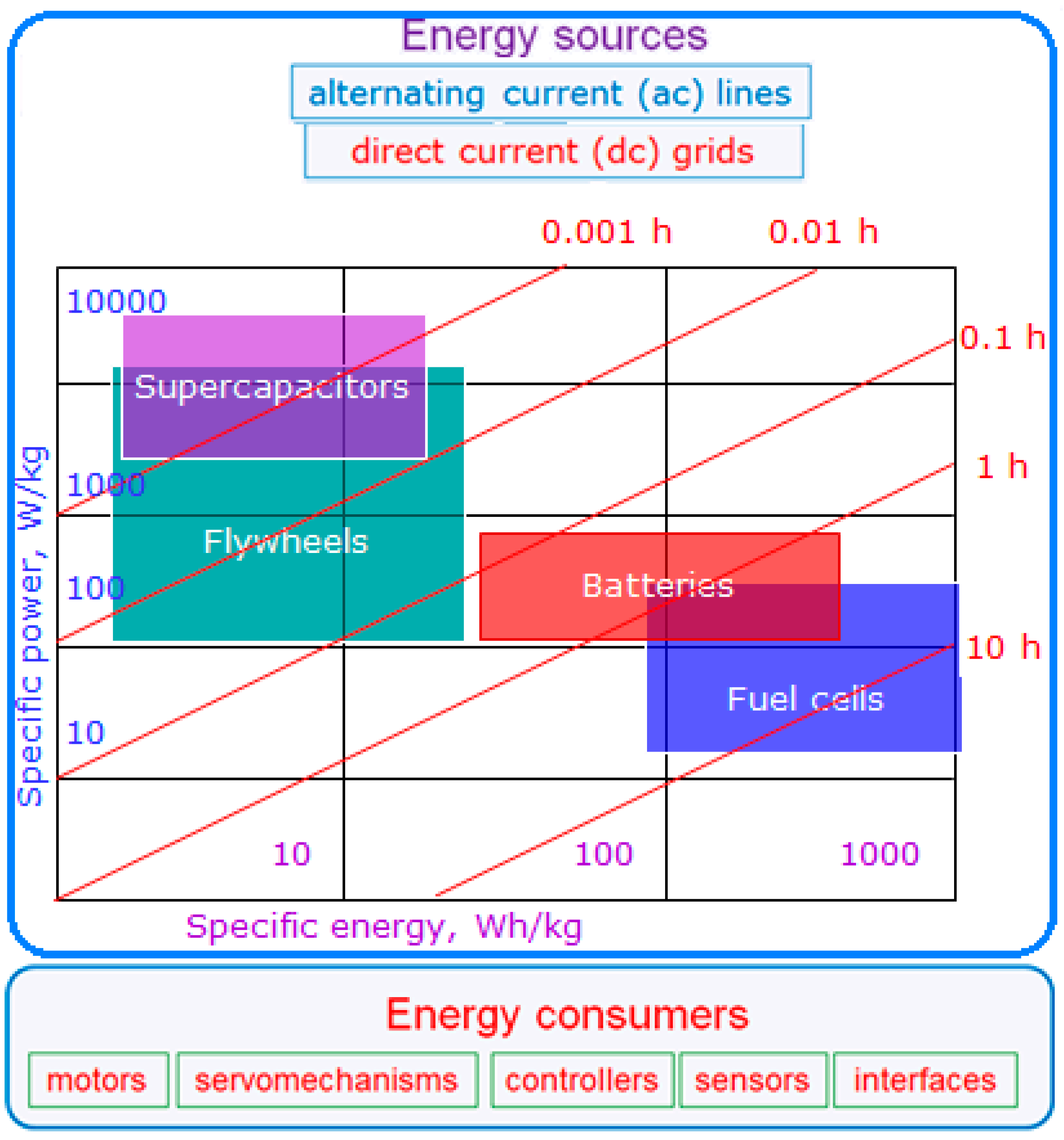
Figure 1. Energy sources and consumers in robotics.
Energies 18 02638 g001
Figure 2. The generalised scheme of energy conversion between AC (blue) and DC (red) grids, sources, and consumers.
Energies 18 02638 g002
Figure 3. General categories of PECs.
Energies 18 02638 g003
Figure 4. The featured characteristics of PEC semiconductor components obtained in this review after analysing online resources and experimental databases.
Energies 18 02638 g004
Figure 5. Operational ranges of semiconductor devices according to [39].
Energies 18 02638 g005
Figure 6. Operational ranges of semiconductor devices obtained after analysing online resources and experimental databases in this review.
Energies 18 02638 g006
Figure 7. A functional circuit of the electrical drive of a separate robot mechanism.
Energies 18 02638 g007
Figure 8. BLDC motor drive (PEC in green, load in blue, control in red).
Energies 18 02638 g008
Figure 9. SRM drive (* means the reference signals).
Energies 18 02638 g009
Figure 10. Step drive.
Energies 18 02638 g010
Table 1. AC/DC converters (rectifiers).
TopologyTypeApplications
Energies 18 02638 i001M1
1-phase
half-wave
midpoint
[47,50]
Energies 18 02638 i002M2
2-phase
full-wave
midpoint
[50,51,52]
Energies 18 02638 i003B2
2-phase
full-wave
bridge
[10,18,32,44]
Energies 18 02638 i004M3
3-phase
full-wave
midpoint
[9,49,53]
Energies 18 02638 i005B6
3-phase
full-wave
bridge
[10,23,49,53]
Table 2. DC/AC converters (inverters).
TopologyTypeApplications
Energies 18 02638 i006M2
half-bridge
VSI
[13,44,66]
Energies 18 02638 i007B2
H-bridge
VSI
[13,43,67]
Energies 18 02638 i008B6V
3-phase
VSI
[44,66,68]
Energies 18 02638 i009B6C
3-phase
CSI
[69]
Energies 18 02638 i0103-phase
ZSI
[48,70,71]
Table 3. AC/AC converters.
TopologyTypeApplications
Energies 18 02638 i011DC-link[4,78]
Energies 18 02638 i012Shared
DC-link
[23,79,80,81]
Energies 18 02638 i013Active front-
end DC-link
[61,62,82,83,84]
Energies 18 02638 i014Matrix[74,85,86,87]
Table 4. DC/DC converters.
TopologyTypeApplications
Energies 18 02638 i015Buck[12,62,90,91]
Energies 18 02638 i016Boost[12,65,92]
Energies 18 02638 i017Buck-boost[12,54,93,94]
Energies 18 02638 i018Isolated[32,54,95]
Energies 18 02638 i019Bidirectional[14,62,65,96,97,98]
Disclaimer/Publisher’s Note: The statements, opinions and data contained in all publications are solely those of the individual author(s) and contributor(s) and not of MDPI and/or the editor(s). MDPI and/or the editor(s) disclaim responsibility for any injury to people or property resulting from any ideas, methods, instructions or products referred to in the content.