Review

The Use of Abandoned Salt Caverns for Energy Storage and Environmental Protection: A Review, Current Status and Future Protections

by
Yun Luo
1,*,
Wei Liu
2,*,
Hongxing Wang
1 and
Keyao Li
1
1
School of Safety Science and Engineering, Chongqing University of Science and Technology, Chongqing 401331, China
2
School of Resource and Safety Engineering, Chongqing University, Chongqing 400044, China
*
Authors to whom correspondence should be addressed.
Energies 2025, 18(10), 2634; https://doi.org/10.3390/en18102634
Submission received: 16 April 2025 / Revised: 16 May 2025 / Accepted: 17 May 2025 / Published: 20 May 2025

Abstract

:
The existence of a large number of abandoned salt caverns in China has posed a great threat to geological safety and environmental protection, and it also wasted enormous underground space resources. To address such problems, comprehensive utilization of these salt caverns has been proposed both currently and in the future, mainly consisting of energy storage and waste disposal. Regarding energy storage in abandoned salt caverns, the storage media, such as gas, oil, compressed air and hydrogen, have been introduced respectively in terms of the current development and future implementation, with site-selection criteria demonstrated in detail. The recommended burial depth of abandoned salt caverns for gas storage is 1000–1500 m, while it should be less than 1000 m for oil storage. Salt cavern compressed air storage has more advantages in construction and energy storage economics. Salt cavern hydrogen storage imposes stricter requirements on surrounding rock tightness, and its location should be near the hydrogen production facilities. The technical idea of storing ammonia in abandoned salt caverns (indirect hydrogen storage) has been proposed to enhance the energy storage density. For the disposal of wastes, including low-level nuclear waste and industrial waste, the applicable conditions, technical difficulties, and research prospects in this field have been reviewed. The disposal of nuclear waste in salt caverns is not currently recommended due to the complex damage mechanism of layered salt rock and the specific locations of salt mines in China. Industrial waste disposal is relatively mature internationally, but in China, policy and technical research require strengthening to promote its application. Furthermore, considering the recovery of salt mines and the development of salt industries, the cooperation between energy storage regions and salt mining regions has been discussed. The economic and environmental benefits of utilizing abandoned salt caverns have been demonstrated. This study provides a solution to handle the abandoned salt caverns in China and globally.

1. Introduction

A large number of underground abandoned salt caverns have been formed due to large-scale exploitation of salt mineral resources in China [1,2]. The high-pressure brine stored in the cavern can partially offset the stress of surrounding rock and delay the creep deformation through the fluid–structure coupling [3]. Due to the low compressibility of brine, the volume convergence rate of the solution cavern in the high-pressure fluid-supported system is very slow, and it usually takes thousands of years to achieve complete closure. At the same time, the low permeability of salt rock (permeability < 10−20 m2) effectively blocks the seepage diffusion of brine into the surrounding rock formations, and this stability mechanism is significant in thick salt domes or thick salt formations. However, the occurrence conditions of salt formations in China are significantly different: buried depths range from several hundred meters to over 3000 m, thin-bedded salt rocks of lacustrine sedimentary origin are mainly developed [4,5,6], and continental clastic rock interlayers are generally developed [7,8]. The tectonic background is mostly graben/half-graben basins controlled by tension fault systems, which are superimposed with late tectonic activation, often associated with tension faults and compressional fracture zones [9,10]. Under this geological background, multiple types of instability phenomena have occurred in the abandoned salt caverns, including differential subsidence of the surface, cavern-roof collapse and micro-seismic events induced by tectonic activation [11], as shown in Figure 1. This complex geological–engineering interaction poses a systemic risk to regional geological safety and ecological barrier function.
According to relevant research data [14], it is estimated that, at end of 2024, the total space volume of abandoned salt caverns in China had already reached 4 × 10⁸ m3. Based on the current annual production capacity of 50 million tons of salt by using well mining in China, the annual increased volume of salt caverns is 2 × 10⁷ m3 (about 21 standard Water Cubic volumes; the Water Cube is the national swimming center venue in China). Because the traditional salt mining mode ignores the control of cavern structural parameters and volume, the storage feasibility of these caverns is significantly shortened, and a large number of irregular caverns are formed, which significantly increases the geological risk. From the perspective of engineering geology, the abandoned salt caverns have dual properties; they are not only geological risk sources, but also can be transformed into underground energy storage facilities [15,16]. For the high-risk caverns, it is necessary to implement the surrounding rock reinforcement and disaster-suppression engineering, such as controlling the roof displacement and reducing the brine seepage through solid waste filling. As for the stable and large caverns, they can be transformed into energy storage space (such as compressed air/hydrogen/oil/natural gas) by engineering reconstruction. It is suggested to implement scientific design standards, form regular caverns through a controlled dissolution process, and establish a three-dimensional real-time monitoring system simultaneously, so as to realize the whole-cycle control of “salt mining–cavern construction–energy storage” and effectively serve the national energy strategic layout.
Salt rock itself has an extensively dense structure, good creep, good thermal conductivity and water-soluble mining, and has become a widely used energy storage medium in the world [17,18], as shown in Figure 2. It is also used for the disposal of alkali wastes, calcium and magnesium mud, and oilfield wastes [19] and for the disposal of nuclear waste under particularly good geological conditions [20]. Since the 1940s, salt caverns were the earliest storage methods for petroleum products, and then in 1959, the Soviet Union built the world’s first salt cavern gas storage [21]. In the 1960s and 1970s, with the global oil crisis, Europe and the United States set off a surge in the construction of salt cavern gas storage. In Europe, Germany, France, Britain and Poland all built a large number of salt cavern gas storages in their territory. The United States has also built a large number of oil and gas storage caverns in deep salt domes along the Gulf Coast [22]. Some of the energy storage caverns in Europe and the United States are rebuilt from abandoned salt caverns, while some are planned for new construction. In particular, from the 1950s to the 1960s, European and American countries have fully recognized the energy storage value of salt caverns and paid special attention to the planning and mining design of cavern groups when solution mining was carried out to ensure that the salt caverns formed after the mining were more valuable [17]. The use of salt caverns to store or sequester CO2 is also one of the research hotspots, and scholars from different regions around the world have conducted a large amount of related research [23,24]. With the gradual deepening of China’s dual carbon target construction work, the use of salt caverns for CO2 storage has broad application prospects in China [25,26]. Feasibility assessments are being conducted in cities such as Zigong in Sichuan Province and Pingdingshan in Henan Province.
In the central and eastern regions of China, especially in the areas adjacent to the West-East Gas Transmission and Sichuan-East Gas Transmission, almost no depleted gas reservoirs and aquifer structures have been found, but there are extremely rich reserves of salt formations [27]. These salt mines have been exploited for a long time and have a large number of underground salt caverns. In recent years, due to pollution, technology and industry depression, salt mining enterprises have also been actively seeking a new direction for development, and the integration of brine mining and comprehensive utilization of the caverns has become the common vision of salt mining enterprises [28]. Although the number of abandoned salt caverns in China is large and widely distributed, in fact, there are still few caverns that are actually used for energy storage or waste disposal. The reason can be summarized as follows: (1) the concept of abandoned salt cavern energy storage is insufficient, only considering the safety angle in the planning of the new caverns; (2) limited by the management mechanism of salt mining enterprises and energy storage enterprises, the coordination mechanism and cooperation mode between salt mining enterprises and energy storage enterprises have not been opened up; (3) in the past few years, the development opportunity of new energy has not been mature, and the demand for salt caverns is not significant; (4) the theoretical and technical studies on the evaluation, renovation and energy storage safety of abandoned salt caverns are not in-depth and systematic. All these reasons restrict the process of transforming abandoned salt caverns to a great extent and affect the development of large-scale energy storage in China.
Focusing on the application of salt caverns for different energy media, energy storage and waste disposal, the research carried out in this paper is as follows: (1) the application status of China’s abandoned salt caverns in the storage of natural gas and oil is summarized, and the suggestion of rebuilding the abandoned salt caverns for oil and gas storage is put forward; (2) the application status of abandoned salt caverns in Compressed Air Energy Storage (CAES) in China is reviewed, and the future development trend towards deep salt cavern utilization and surface-underground coordination is pointed out; (3) the current situation of rebuilding hydrogen storage in abandoned salt caverns is analyzed, and the problems of hydrogen storage in abandoned salt caverns are pointed out. In the future, the technical route of ammonia storage and methanol storage should be developed; (4) the application status of the abandoned salt caverns in the disposal of wastes is investigated, and the key problems of the salt cavern waste disposal are analyzed. This study discusses the major application prospects of the abandoned salt caverns in the field of energy storage and waste disposal and discusses that the surface and underground cooperative development should be taken seriously when storing different media in abandoned salt caverns. The research results provide a useful reference for the comprehensive utilization of the abandoned salt caverns and salt mine disaster management in China and abroad.

2. Salt Cavern for Hydrocarbon Storage

2.1. Storage of Gas (Gas Storage)

Salt rock is the term in rock mechanics for salt deposits. Its porosity is usually only 0.1–0.5% and permeability is as low as 10−20–10−22 m2 [29], and it is almost the densest rock in the crust. Salt rock also has unique characteristics such as water-soluble mining, good plasticity and damage self-healing [30], so the salt caverns are used as ideal storage places for oil and gas and other energy sources because they will not cause leakage and chemical reactions. In addition, storing oil and gas in the salt caverns can also effectively prevent contact with air, lightning, etc., so that their safety can be further improved. Moreover, because the depth of the salt cavern is large (usually 500–2000 m), it can also effectively prevent attacks from almost all kinds of weapons. Compared with the ground storage tanks, the salt cavern storage not only has good safety performance and scale advantages, but also covers an area of only 1/10 of the above ground storage tank, and the construction cost is usually only 1/3 of the former [31]. In addition, because the temperature in the deep underground is generally higher than that on the surface (the pressure gradient below the surface is 2–3 °C/100 m), it is also extremely favorable for maintaining the quality of oil.
The many advantages of salt rock make underground salt caverns an ideal choice for oil and gas storage. However, many abandoned salt caverns exhibit irregular geometries because the cavern shapes were not specially controlled during the salt mining stage. This poses risks for gas/oil storage due to the potential surrounding rock collapse, while their limited volumes further constrain storage capacity. Besides, the wells and tubes in abandoned salt caverns may be damaged or weakened because of the long-term erosion by brine [32]. It may lead to instability of the wellbore and leakage of stored substances, and the renovation of the wellbore and tubing is necessary. For deep abandoned salt caverns repurposed for gas storage, the repeated pressure changes during the injection/extraction process may induce cracks in the surrounding rock over time. This is unfavorable for the long-term stable operation of the salt cavern gas storage.
It is well known that natural gas production areas and consumption areas often have spatial mismatches. China’s natural gas production is mainly concentrated in the western regions [33], of which Shaanxi, Sichuan and Xinjiang account for a relatively high percentage, and the three provinces (autonomous regions) together have a capacity of more than 70%. In the central and eastern natural gas main consumption areas, natural gas resources are relatively scarce. In addition, the consumption of natural gas also has a relatively high seasonality and time period, and the consumption of natural gas in winter is often much higher than that in summer. According to international practice, natural gas storage should reach 15–18% of the annual consumption in order to effectively ensure the stability of the natural gas market. Sometimes, for countries or regions with high dependence on natural gas imports, the storage amount of natural gas is often higher. According to the ratio of 15–18%, with China’s annual natural gas consumption of 4.26 × 10¹² m3 in 2024, the required natural gas storage should reach 63.9 to 76.7 billion m3. The existing types of gas storage facilities in China are mainly depleted gas reservoirs and salt caverns, which cannot meet the social demand of natural gas storage. Furthermore, most of the existing gas storage is the depleted gas reservoir type in China [34], which is generally only suitable for seasonal peak regulation. For short-term peak regulation, such as emergency peak regulation and daily peak regulation required by the natural gas market, it is necessary to build more salt cavern gas storage, thus taking full advantage of flexible injection and production and the rapid response of salt cavern gas storage.
China’s salt mineral resources have significant geological advantages. This specific geological space and natural gas strategic reserve demand form a spatial–temporal matching: (1) the spatial coupling degree analysis shows that the main salt mining areas (Ordos Basin, Sichuan Basin, etc.) and the “West-east gas transmission”, “China-Russia East Route” and other main pipelines overlap more than 62%; (2) the calculation of demand-matching degree shows that 85% of the salt mineral resources are distributed in the radius of 200 km from the main natural gas consumption areas (Yangtze River Delta and Beijing-Tianjin-Hebei city cluster). Figure 3 below shows the spatial coupling relationship between salt mine distribution and the pipe network system.
The construction status of gas storage using abandoned salt caverns in China is as follows:
(1) Since 2007, Jintan of Jiangsu has started using six abandoned salt caverns for the first time [35], with a single cavern storage capacity of 100,000–150,000 m3 and a total working gas volume of 89 million m3 (equivalent to 63,000 tons of Liquefied Natural Gas (LNG) energy storage). It has been operating safely and stably for 18 years, indicating the feasibility of converting abandoned salt caverns into gas storage. Then, Ganghua Gas started a total of 25 abandoned salt caverns to rebuild gas storage in Jintan, with a total gas storage capacity of 1.2 billion m3 after completion.
(2) In 2021, China National Petroleum Corporation (CNPC) started the reconstruction project of abandoned horizontal salt caverns in Ye County, Pingdingshan, Henan Province [36]. The storage capacity of a single pair of salt caverns can reach 100 million m3 after the implementation of gas storage. It is expected that a total of 10 pairs of well groups will be rebuilt, and a total gas storage capacity of 1 billion m3 will be formed after completion.
(3) In 2022, the State Pipeline Network started the reconstruction project of abandoned horizontal salt caverns in Huai’an, Jiangsu Province. This is the world’s first salt cavern storage using sediment void space to store gas, and it will provide an engineering demonstration for low-grade salt reservoir energy storage in China.
The biggest advantage of using the abandoned salt cavern to rebuild the gas storage is to save time in cavern construction, reduce the investment of cavern construction and shorten the return period of investment. At the same time, it can also reuse the existing ground brine transport pipeline facilities of the salt chemical industry to improve the utilization rate of infrastructures. Therefore, the use of abandoned salt caverns to rebuild gas storage should be developed as the mainstream idea and basic practice in the field of salt cavern gas storage.
The following scientific construction principles should be followed for the reconstruction of abandoned salt cavern gas storage:
(1) The optimal buried depth of the gas storage should be controlled in the range of 500–2000 m. Based on the gas equation of state (for ideal gas, P V = n R T ), the gas storage pressure is linearly positively correlated with the buried depth (setting gradient as 0.023 MPa/m), and the gas storage capacity can be increased by 2.3% with every 100 m increase in depth. At the same time, when the buried depth is >800 m, the sealing efficiency of the cap rock usually increases with the buried depth. It is recommended to preferentially select the 1000–1500 m depth section, which is both economical and geologically safe.
(2) The effective volume of a single cavern should be ≥8 × 10⁴ m3, and multi-cavern group collaborative operation should be implemented. In view of the fixed cost of drilling engineering (about 30–50 million Yuan per well), when the total storage capacity is >5 × 10⁸ m3, the unit storage construction cost can be reduced by 40–60%. It is recommended to adopt the mode of “Central well site + radial well pattern”, and the pillar space between the cavern groups should be > 1.5 times the maximum cavern diameter to avoid stress interference [37].
(3) Implement differentiated salt formation development strategies: when the salt formation grade is ≥80% (such as Jintan salt mine), the main cavern can be directly used to store gas (space utilization rate > 75%); when the salt layer grade is 30–80%, it is necessary to adopt the sediment pore gas storage technology and determine the effective porosity through permeability compensation calculation. The experiment shows that the porosity of the sediment can reach 30–40% [38].
(4) The design life should be extended to 50 years. Comparative analysis shows that the volume shrinkage rate of salt caverns in bedded salt rock (the main type in China) is < 0.3%/a, which is significantly lower than that of salt dome formation (0.8–1.2%/a). Considering the compressive strength of roof and floor > 35 MPa and the thickness of interlayer > 5 m, the safety threshold of cumulative deformation < 15% in 50 years is completely controllable. It is recommended to introduce a time-varying damage model for life verification.
(5) To establish a geological adaptation evaluation system, as mechanical criteria, one can consider the maximum principal stress difference < 8 MPa and the proportion of plastic zone < 20%; sealing criteria, interlayer permeability ≤ 1 × 10⁻¹⁷ m2 and breakthrough pressure > 12 MPa; morphological criteria, diameter to height ratio 1:2–1:3 (vertical cavern), distortion rate < 10%; layout criteria, pillar width > 1.5 times the diameter of the cavern, adjacent cavern pressure difference < 2 MPa. It is recommended to use three-dimensional (3D) geomechanical simulation for special demonstration.

2.2. Salt Cavern Oil Storage

For oil-importing countries, the construction of oil strategic reserves and commercial reserves is of great significance to ensure a country’s oil security. In 1993, China changed from an oil-exporting country to an importing country, and the government deployed the oil reserve accordingly. The first phase of the National Petroleum Reserve was completed by the end of 2014, holding 12.43 million tons of crude oil in four national petroleum reserve bases, equivalent to about 91 million barrels. The four bases are located in Zhoushan, Zhenhai, Dalian and Huangdao. All four bases are located in coastal areas and are stored in the form of above-ground storage tanks, but their total oil storage is equivalent to only about nine days’ consumption. They are all surface storage tanks in coastal areas, and their radiation capacity and safety performance are concerning. Syria’s port storage system was disabled by North Atlantic Treaty Organization (NATO) missile attacks [39]. The second phase of the National Strategic Reserve project began site planning in 2003, including Jinzhou in Liaoning Province, Qingdao in Shandong Province, Jintan in Jiangsu Province, Zhoushan in Zhejiang Province, Huizhou in Guangdong Province, Dushanzi in Xinjiang Uygur Autonomous Region and Lanzhou in Gansu Province, with a total energy storage capacity of 26.7 million m3. Compared with the first phase of the reserve base, the second phase of the national strategic petroleum reserve is located in Xinjiang and Gansu and began to tilt to the central and western regions, while the first phase of the strategic petroleum reserve base is located in the coastal areas, considering their economic functions, in order to ensure the adequate supply of energy in China and ensure the needs of economic development are met. The layout in the central and western regions may be more out of strategic and tactical considerations, in order to prepare for sudden energy security issues such as war and other extreme events.
The international strategic petroleum reserve system is undergoing a paradigm shift from surface facilities to deep geological storage. According to the International Energy Agency (IEA) 2023 report [40], 68.4% of the world’s strategic petroleum reserves rely on salt cavern storage. The operation principle of salt cavern oil storage is as shown in Figure 4. Its technical advantages are reflected in three aspects: (1) strategic concealment and damage resistance. As an example, 500 m to deep salt caverns by the earth stress shielding effect (σv > 11.5 MPa) can resist drilling weapons (MOP ≥ 6) and Richter magnitude 7 earthquakes; there are only small injection and production wellheads on the ground, and it is difficult for satellites to accurately identify. (2) Engineering economic advantages because the construction period of the abandoned salt cavern to rebuild the oil storage facility is shorter than that of the new cavern, and generally only 1–2 years can be completed. The deployment of 3 million tons base can be achieved by 7 × 500,000 m3 salt cavern cluster. (3) More geo-adaptive because there are giant salt mines and a large number of abandoned salt caverns in southwest China and Jianghan Basin, and they are located in the safe depth area on the west side of the “Hu Huanyong Line”, forming a natural coupling with Lanzhou–Chengdu–Chongqing, China–Myanmar and other oil pipelines. Therefore, in the abandoned salt cavern reconstruction oil storage, the construction period, capital investment, location radiation and other aspects are more significant advantages than in the ground storage tank, hard rock cavity and new salt cavern. Therefore, it is suggested that in the current and future new construction and planning of oil storage, the abandoned salt cavern reconstruction of oil storage is listed as the first position.
However, there are also some problems hindering the practical application of abandoned salt caverns to oil storage [41]. During oil storage, the injection and extraction of oil are achieved through brine displacement, and the aging of the wellbore and tubing in abandoned salt caverns poses a threat to the safety of oil injection and extraction. Salt caverns that have been idle for a long time will experience volume shrinkage due to salt rock creep, and the injection and extraction cycles for oil storage are relatively long, allowing for more thorough heat exchange between the brine and oil with the surrounding rock and leading to the expansion of brine and oil. The combined effect of cavern shrinkage and expansion of the storage medium puts higher demands on the stability of the salt cavern and the wellhead equipment. Moreover, oil will cause erosion of impurities and interlayers in the layered salt rock, which in turn affects the stability and tightness of the salt cavern oil storage. Additionally, when the accumulation of sediment at the bottom of the cavern in a high-impurity salt layer is high, it will encroach on the effective volume of the cavern, making it difficult to use because the effective volume of the salt cavern does not meet the standard.
Based on the optimization goal of geological storage efficiency and economy, the planning and construction of salt cavern oil storage depots should follow the following guidelines:
(1) In terms of location, the southwest and central regions of China with more strategic depths are preferred, and the coupling of strategic reserves (>90 days of net import) and commercial reserves (20–30 days of refining and chemical demand) is realized by relying on the Lanzhou–Chengdu–Chongqing and China–Myanmar crude oil pipeline layouts and reserve systems, so as to improve regional energy elasticity.
(2) The depth of salt cavern oil storage should be in the 500–1000 m range. When the formation is too shallow, the thickness of the overlying strata is not enough, the sealing property of the cavern as a whole is not enough, and once leakage occurs, it is easy to pollute the overlying aquifer. Here, we consider that oil has very low compressibility, and increasing the depth will slightly affect the storage capacity but will increase the cost of cavern construction and the difficulty of injection and production.
(3) The volume of a single salt cavern is not less than 100,000 m3, and the storage amount of a single oil storage base is not less than one million tons. Salt cavern oil storage requires the construction of brine injection and production systems, oil pipelines and ground pumping systems. Ensure a reserve of not less than one million tons to guarantee reasonable investment. The petroleum medium stored can be crude oil or refined oil.
(4) The injection and production system shall be designed cooperatively. Conventional mode: brine storage pool is built on the ground, and the distance between the brine treatment plant is recommended < 15 km; oil and gas storage collaborative mode: coupling gas storage to implement gas–oil mutual drive, but the oil storage must be built in accordance with the gas storage standards, so there is no need to build brine buffer pool.
(5) Salt cavern oil storage should give priority to high-grade salt formations and regular cavern shape. As far as possible, the salt cavern should be the first choice of clean space for oil storage, as it has a clear oil-brine interface, it is obvious that this requires a high-grade salt layer, and the cavern shape is more regular. Although there have been cases of gas storage in a low-grade salt layer, it is not considered feasible to store oil in pores of sedimentary rocks at present.
If the cavern meets the above basic conditions, then the related demonstration of the construction of salt cavern oil storage can be carried out. At present, it is suggested to give priority to the abandoned salt caverns of a single well to carry out the oil storage demonstration. In addition, the above conditions are only recommended measures rather than mandatory measures, for in the place where it is necessary to build a storage facility but there is conflict with the relevant recommendations, the feasibility of the construction of oil storage can be determined through special demonstration.

2.3. Comparison Between Gas and Oil Storage

Under the same salt cavern volume condition, the effective volume of gas storage increases positively with the increase of depth, and its economic improvement is mainly due to the gas compression effect brought by high pressure environment; however, the effective volume of oil storage is insensitive to the depth change, and the construction cost increases exponentially with the depth. Based on this, it is suggested that the abandoned salt cavern with a depth of less than 1000 m should be planned as an oil storage first, while the salt cavern with a depth of more than 1000 m is more suitable for the construction of gas storage. From the perspective of geological stability, the fluctuation range of the working pressure of oil storage (usually < 2 MPa) is significantly smaller than that of gas storage (conventional fluctuation > 5 MPa), and the stability control standard of surrounding rock can be reduced by about 30%. In terms of fluid characteristics, the dynamic viscosity of petroleum (10−1–102 Pa·s) is 3–5 orders of magnitude higher than that of natural gas (10−5 Pa·s), resulting in a reduction of 2–3 orders of magnitude in its penetration rate, which means the cavern tightness of oil storage can be much better than that of gas storage. In summary, the site selection of the oil storage has lower requirements than that of gas storage in terms of structural stability and cap integrity, so the site selection range can be expanded much larger.

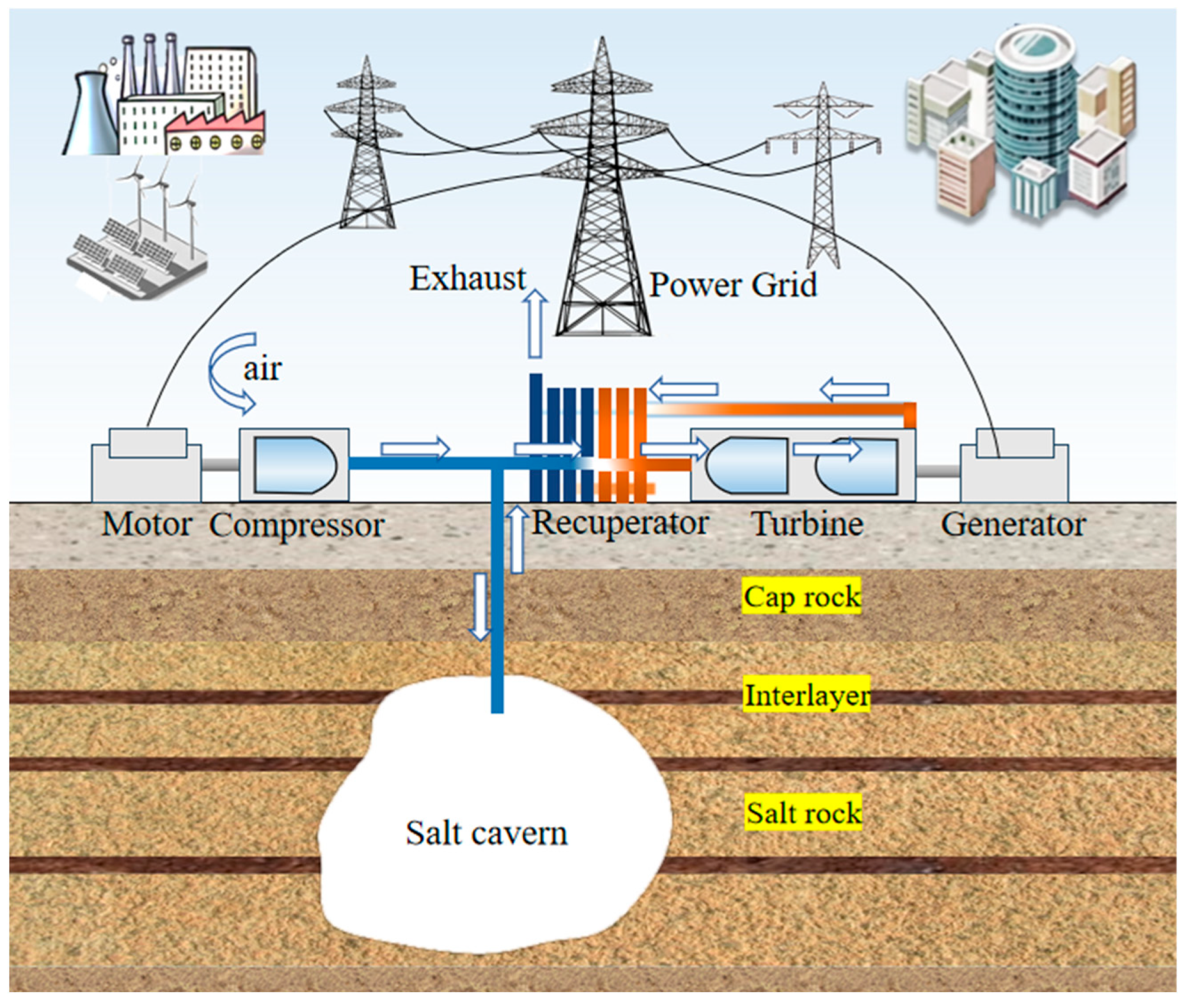
3. Compressed Air Energy Storage

3.1. Basic Principles

The CAES built by using the underground salt cavern can hold large-scale and long-term energy storage [42]. The core principle is to use the salt caverns as storage containers for high-pressure air to realize the “storage-release” cycle of electric energy (Figure 5). The technical principle is as follows.
Energy storage stage (Charging process): in the grid power surplus (such as renewable energy generation peak or electricity consumption trough), electric energy is used to drive the compressor, bringing the air compression to a high pressure (usually 10–20 MPa). The heat generated during the compression process can be recovered through thermal energy storage systems (such as molten salt or heat storage tanks) or directly discharged (conventional CAES). High-pressure air is injected into an underground salt cavern for storage, forming a “compressed air storage space”.
Energy release stage (Discharging process): when the grid needs to replenish power (such as peak consumption or insufficient renewable energy output), the stored high-pressure air is released from the salt caverns. The released air is heated (traditional CAES burns natural gas for heat; advanced adiabatic systems use stored heat) and expands to drive turbines that generate electricity, which is fed back to the grid.

3.2. CAES Salt Cavern Type Characteristics

As the preferred geological compressed air large-scale energy storage system, the technical and economic advantages of salt cavern-CAES can be demonstrated through the following four-dimensional comparison system:
(1)
Comparison of sealing mechanism
Salt rock has intrinsic sealing characteristics (permeability less than 1 × 10⁻²⁰ m2) and has good plasticity. It can repair micro-cracks through dynamic recrystallization under certain pressure and brine conditions [30]. On the other hand, the hard rock cavity needs a 0.5–1.2 m thick steel concrete lining (the cost may account for more than 40%), and the interfacial debonding rate increases exponentially with the number of pressure cycles. Domestically, a CAES power station is now approved, prioritizing the underground salt cavern.
(2)
Mechanical response characteristics
The viscoelastic constitutive relation (Norton-Hoff model [14]) of salt rock endows it with excellent pressure-buffering ability. Seasonal peak load mode: operating pressure (0.3–0.8)σvv = γh, γ is 23 kN/m3), corresponding cavern volume shrinkage rate is generally < 1% per year [43]; daily peaking mode: (0.6–0.8)σv pressure domain, as the average gas pressure is higher that of natural gas storage, so the cavern volume shrinkage will be lower. Under the pressure fluctuation of ΔP > 5 MPa in granite cavity, once damage is formed in the lining system, it is very difficult to repair.
(3)
Calibration of energy storage capacity
Take typical salt cavern energy storage parameters in China as an example, see Table 1.
(4)
Economic comparison of construction cycle
The cost composition of the whole process of the reconstruction of the abandoned salt cavern gas storage for a CAES power station includes: (1) brine treatment: the brine discharge cost is about 5–10 Yuan/m3. Such a low cost is because the income of brine can offset 30–50% of the discharge cost; (2) well group project: mainly gas injection wells, brine drainage wells and existing old wells reconstruction or sealing, this cost accounts for over 60% of the total underground engineering cost; (3) cycle control: since only wells are rebuilt and gas injection and brine drainage, the construction cycle can be reduced to 1.5–2.0 years, but hard rock cavity generally takes 3–5 years. Preliminary calculation shows that the cost of rebuilding the abandoned salt cavern gas storage for CAES power station is 40–60% lower than that of the hard rock scheme.

3.3. Current Situation and Future Direction of CAES

In the history of compressed air energy storage technology, the Huntorf power station in Germany built the world’s first salt cavern-type commercial CAES system in 1978 [44]; its installed capacity is 290 MW, using underground salt cavern gas storage and relying on natural gas secondary combustion power generation, and it has been in operation for 46 years. In 1991, McIntosh Power Station in Alabama was put into operation as the second salt cavern-CAES commercial facility in the world [45] with an installed capacity of 110 MW, and the same supplementary combustion technology was adopted. The project measured data verified [44,45] that the overall system efficiencies of the two power stations are as follows: Huntorf power station about 42%, McIntosh power station about 54%. Compared with the 60% to 70% efficiency level of adiabatic CAES technology [46], the energy loss is mainly from the compression heat waste and the combustion of natural gas during the power-generation stage. In addition, the combustion process produces carbon dioxide emissions; for example, the Huntorf station emits about 100,000 tons of CO2 per year, which fundamentally contradicts the goal of carbon neutrality.
It is precisely because of the above technical defects that traditional post-combustion CAES has dual constraints. Fossil fuel dependence weakens its value as a pure energy storage system. The carbon emission characteristics do not meet the sustainable development requirements of the new energy power system. This explains why only two commercial-grade supplementary combustion CAES power stations have been built worldwide in the past 30 years.
In recent years, the CAES technology has achieved major breakthroughs through non-fired systems. The technology adopts the integrated scheme of compression heat step recovery and heat storage system. In the energy storage stage, the compression heat generated by the compressor is recovered by phase change material or molten salt heat storage device, and the stored heat is used to heat the air before expansion in the energy release stage, so as to get rid of the dependence on natural gas secondary combustion. According to the data reported by the project owners [47,48], the energy round-trip efficiency of the non-supplementary combustion CAES system has been improved to 60–70% (Jintan 60 MW project up to 60%, Tai’an 350 MW project target efficiency 65–70%).
In contrast, although a Pumped Hydro Energy Station (PHES) has a higher system efficiency advantage of 70–80%, its construction cost is as high as 6000–8000 Yuan/kW, which is equal or higher than that of salt cavern-type CAES with a cost of 4500–8000 Yuan/kW. But PHES faces significant geographical limitations (need to have a height difference of 100–700 m of dual reservoir terrain) and ecological impact (reservoir inundated area of an average of 10–15 km2/GW). Salt cavern CAES shows multiple comparative advantages: (1) economy: relying on the existing salt caverns to reconstruct gas storage, the unit investment cost is reduced by 30–40% compared with extraction storage; (2) construction cycle: the typical construction cycle of a project is 1–2 years, but PHES projects need a much longer time; (3) ecological compatibility: there is no need for constructing huge water reservoirs, and the carbon emission intensity is only 1/5 of that of extraction and storage; (4) efficiency gap: the system efficiency gap is narrowed to 10–15%, and the space-utilization rate can be further optimized through supercritical compression technology (gas storage pressure is increased to 15–20 MPa).
The above technical and economic characteristics are making the proportion of salt cavern-type CAES in the planning of new energy storage installations in 2025 significantly increase. Especially in the supporting scenes of large scenery bases, its 4–24 h long-term energy storage characteristics and pumping storage form complementary functions, becoming the core technology option to support a high proportion of the renewable energy grid.
In 2022, the Jiangsu Jintan 60 MW CAES power station had been completed using an abandoned salt cavern with a depth about 1000 m. The volume of the salt cavern is about 200,000 m3, and the energy conversion efficiency is reported as 65% [48]. This is also the first non-secondary combustion type compressed air energy storage power station in China. The total investment of the power station is only 500 million Yuan. Jiangsu Jintan also plans to build a 1000 MW CAES power station, which only uses abandoned salt caverns. In 2024, the 300 MW CAES power station in Yingcheng, Hubei (the world’s largest) had been put into operation, and it was the first in the world to use abandoned horizontal connected caverns for gas storage. The operation mode of the CAES power station is 5 h power release, 8 h power storage per day, which is mainly used to balance the load of the grid. It is expected to generate about 500 million kWh of electricity per year and reduce 1.2 million tons of carbon dioxide emissions. At present, there is an upsurge in the construction of salt cavern-type CAES power stations in China. In Feicheng and Heze of Shandong Province, Pingdingshan of Henan Province, Qianjiang of Hubei Province, Zhangshu of Jiangxi Province, Anning of Yunnan Province and other places, there are projects approved for the construction of CAES storage using abandoned salt caverns.
Salt cavern-type CAES power stations have made great progress in China, but the technology is extensively complex and is still in its infancy, and the following core scientific problems still need to be overcome for its large-scale application.
(1)
Pressure-coupling optimization of surface–underground system
The upper limit of the working pressure of the existing ground compressor/expander is generally 10 MPa, while the operating pressure of the deep salt cavern, such as depth > 1500 m, needs to be much higher to match the formation stress. For instance, in a 1500 m depth salt cavern used as gas storage, the safe gas operation range for CAES should be 20.7–27.6 MPa (0.6–0.8)σv, which is already much higher than 10 MPa. A multi-stage compression–expansion system needs to be built in this way. It should be verified that the multi-stage compression improves the system efficiency, but the domestic has not yet broken through the fatigue design of a 20 MPa compressor.
(2)
Thermodynamic constraint modeling of energy storage capacity
At present, there is a mismatch between installed power capacity and cavern storage capacity in domestic CAES projects, so it is necessary to establish the relationship between installed capacity (P) and salt cavern parameters:
P = V × ( P max P min ) × η t h 3.6 × 1 0 6 × t
where, V is the effective volume of the salt cavern storage (m3), ηth is the electric energy conversion efficiency of CAES system, taken as 0.7, and t is the discharge time (h). Pmax and Pmin are the maximum and minimum operating pressure, respectively (MPa).
Taking a 520 m depth salt cavern in Yingcheng, Hubei as an example, which has a cavern volume of 4.2 × 10⁵ m3 and a gas operation range of 7–9.2 MPa, the theoretical installed capacity limit should be as below:
P = 420,000 × ( 9.2 7 ) × 0.7 3.6 × 1 0 6 × 5 = 3590 MW
The designed installed capacity of this CAES power station is 300 MW, which is in accord with the theoretical calculation.
However, correspondingly, the installed capacity of Hubei Qianjiang salt cavern (depth 1300 m, Pmax = 20.93 MPa) should reach 977 MW under the same volume and proportional pressure difference, but the actual planned installed capacity is only 350 MW, which exposes the defects of the current planning method.
(3)
Geomechanical design of dynamic pressure window
The early CAES in the United States and Germany used a fixed pressure range of 2–3 MPa (Huntorf: 4–7 MPa, McIntosh: 5–7 MPa), but the parameter system was not universal. The safety window pressure should be calculated according to the salt cavern creep constitutive equation [14]:
ε ˙ = A σ n e Q / R T
where, ε ˙ is the steady state creep strain rate; A is the material characteristics parameter, a−1; σ is the stress deviation; n is the constant of stress exponent, MPa−1; Q is the creep activation energy; R is the universal gas constant, 8.314 J/(mol·K); and T is temperature, K. The salt cavern compressed air storage includes a cyclic operation mode consisting of frequent injection-production and constant pressure stages, which causes the surrounding rock to experience dual effects of fatigue and creep. Due to the strong creep ability of salt rock, the creep characteristics of salt rock under different external conditions have attracted much attention [49]. The research results have important guiding significance for gas pressure setting. In addition to the classic creep model of salt rock given in Equation (2), relevant scholars have established empirical models of salt rock creep based on experimental results. Common empirical creep models mainly include exponential, power, and logarithmic models [50], and the expressions of some models are as follows:
ε ˙ = m 7 ( σ / σ c p 7 1 e t / n 7 + t e Q / R T + ( 1 / t F t )
ε ˙ = m 8 t n 8 σ 1 σ 3 p 8
ε ˙ = m 9 + n 9 log t + p 9 t
where, m i , n i , and p i (i = 7, 8, 9) are the characteristics parameter, which is related to the material itself and experimental conditions; σ is the stress in different directions (MPa); t is the duration of the experiment (h); and t F is the time of sample failure (h).
Equations (3)–(5) are applicable for analyzing the creep behavior of salt rock under specific conditions, but in practical engineering, the operating conditions of salt cavern-CAES power stations are more complex, and the geological environment is also diverse. Therefore, relevant scholars have established different creep models of salt rock under multi-factor coupling effects [51,52], such as temperature stress coupling, loading unloading and creep coupling, based on actual conditions. They are of great significance for ensuring the safe operation of CAES systems, but the forms of these models are usually complex, and there are certain difficulties in practical applications.
China’s layered salt rock is recommended to take (0.5–0.7)σvv = 0.023 h MPa, h is buried depth, m). For example, the gas operation range of a 1200 m depth salt cavern should be designed to 13.8–19.32 MPa, with a pressure difference of 5.52 MPa, rather than simply follow the 2–3 MPa pressure difference.

4. Storage of Hydrogen and Others

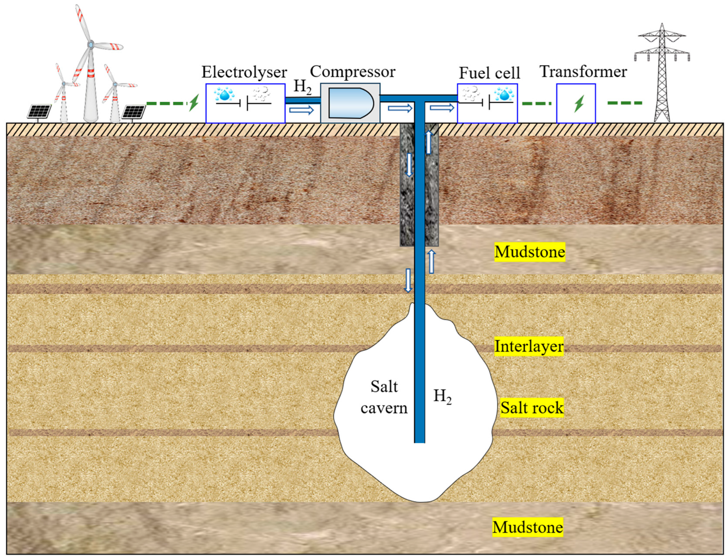
4.1. Abandoned Salt Caverns for Hydrogen Storage

On the power source side, the power output of renewable energy has typical volatility, randomness and irregularity, which makes it extremely difficult to connect to the grid. Hydrogen production by electrolysis of excess electricity during peak period and storage in underground space such as salt caverns (Figure 6) and electricity generation by hydrogen energy during valley value period are effective models for implementing peak cutting and valley filling with renewable energy. Compared with CAES, hydrogen storage in an underground space has higher energy density and longer peak load time and is known as another important way of large-scale long-term energy storage [53] which has attracted much attention. The salt cavern itself is known as the first choice for large-scale hydrogen storage due to its dense surrounding rock structure, stable chemical properties and flexible injection and production [54]. The four existing hydrogen storage projects in the world all use salt caverns (H2 purity > 95%), of which the hydrogen storage amount of the Spindletop project is 13,100 tons. They have been in operation for more than 50 years, which fully demonstrates the safety, feasibility and large-scale advantages of hydrogen storage in salt caverns.
Compared with the storage of natural gas and compressed air, hydrogen has higher safety requirements for the sealing of the formation due to its strong activity, strong diffusion and strong permeability [55]. As a gas with the smallest molecular weight and strong reducibility, when selecting the storage site, the permeability of hydrogen in the surrounding rock and the possible biochemical reactions with the surrounding rock should be fully considered. The reaction consumes hydrogen, and the products produced may contaminate the stored hydrogen. In the selection of tubing materials, hydrogen corrosion-resistant and anti-hydrogen embrittlement materials should be considered to meet durability and airtightness requirements. In addition, in order to adjust the peak regulation of renewable energy, the frequency of hydrogen injection and production is higher, and the surrounding rock is subjected to stronger fatigue creep characteristics, and the pressure operation period and injection and production frequency should also be included in the stability evaluation range [56]. The preliminary suggestions are as follows: (1) the abandoned salt cavern suitable for storage of natural gas can be included in the construction scope of hydrogen storage, and the abandoned salt cavern that does not even meet the requirements for gas storage should generally not be considered for reconstruction of hydrogen storage; (2) the non-salt interlayers and the roof should be given priority as plaster mudstone formation because salt rock and gypsum mudstone interlayers have much lower permeability than other rocks; (3) the site selection of salt cavern hydrogen storage should also be near the scenic power generation site or hydrogen production base to reduce the cost of pipeline transportation and reduce the risk of pipeline transportation. At present, priority should be given to the storage and utilization of industrial by-product hydrogen (gray hydrogen/blue hydrogen), and the storage and utilization of renewable energy hydrogen production (green hydrogen) should be considered in the medium and long term [57].
Based on the thermodynamic model of hydrogen storage in salt caverns, the benchmark parameters are set as follows: cavern depth 1000 m, vertical ground stress equal to 23 MPa at the depth of cavern roof, cavern effective volume 5 × 10⁵ m3, and gas working pressure P = 10 MPa. The stored gas mass can be calculated according to the real gas state equation [58]:
m H 2 = P V Z R T M H 2 = 1 0 7 5 × 1 0 5 1.12 8.314 313 2 × 1 0 3 = 4.5 × 1 0 6 kg
where, P, V and T are pressure, volume, and temperature of the gas, respectively; Z is the compression factor of the gas; and R is the gas state constant, taken as 8.314 J/(mol·K).
Considering a 60% fuel cell efficiency [59], a single injection–production cycle can release the following energy amount:
E = 4.5 × 1 0 6 kg × 33.3 kW h / kg × 0.6 = 8.9 × 1 0 7 kWh
In 2024, Yang et al. [60] indicated that the demand for hydrogen storage in salt caverns of China will reach 260.6 × 10⁴ tons in 2060, and the corresponding number of salt caverns needs to be built:
N = 260.6 × 1 0 4 t 4.5 × 1 0 6 t 579
That is to say, up to 2060, the needed salt cavern number for hydrogen storage will be about 579, and the needed salt cavern volume will be 2.896 × 10⁸ m3. At present, the Jintan salt cavern gas storage site has about 60 salt caverns in total, but most of the salt cavern volume is in the range of (20–30) × 104 m3. To fulfill the hydrogen storage in salt caverns in 2060, China’s government will need build 20 salt cavern hydrogen storage projects like Jintan, and China must develop the use of salt basin resources in different regions, such as Sichuan salt mine, Yunnan salt mine and so on. In the future, salt cavern hydrogen storage will play a key role in the national hydrogen energy strategy.

4.2. Indirect Hydrogen Storage Ideas

The storage and transportation system of hydrogen is faced with three bottlenecks: the volume energy density of gaseous hydrogen storage is only 2.8–4.5 MJ/m3, the unit energy storage cost of liquid hydrogen process exceeds $15/kg, and the intrinsic safety risk brought by the wide explosion limit of 4–75%. The chemical carrier hydrogen storage technology based on Power-to-X (PtX) has become a breakthrough direction, and the hydrogen is fixed in ammonia/alcohol compounds through catalytic conversion. One typical path is Haber ammonia synthesis (3H2 + N2→2NH3, (400–500) °C/(15–25) MPa). The technology path of hydrogen storage based on green hydrogen synthesis ammonia (green ammonia) can be divided into three steps: first, hydrogen is produced by electrolyzing water with renewable energy, and zero carbon ammonia is synthesized by the Haber process; secondly, ammonia is easy to liquefy (atmospheric pressure −33.4 °C) for compression storage, or configured as high solubility ammonia (1 L of water can dissolve 702 L NH3 under standard conditions); finally, it will be transported to the salt cavern by pipeline/tank truck for large-scale storage. At the end of utilization, the high-efficiency release of ammonia gas (conversion rate > 95%) can be achieved through the medium temperature pyrolysis technology at 120–200 °C, and its volume energy density of 17.8 MJ/L is significantly better than that of liquid hydrogen (8.5 MJ/L).
At present, China has a mature ammonia industry foundation. The liquid ammonia production capacity exceeds 60 million tons in 2022. But, limited by the technical bottleneck of ammonia energy utilization, the annual ammonia circulation in the industrial field only accounts for 23% of the production capacity. Salt cavern ammonia brine storage technology has dual strategic value: (1) a single 500,000 m3 salt cavern can store 350,000 tons of ammonia, equivalent to 74,000 tons of hydrogen or equivalent to 264 GWh energy storage capacity, which solves the core problem of insufficient hydrogen energy storage density; (2) relying on the geological sealing of the salt caverns, the multi-quarter “Ammonia production-Ammonia storage-Ammonia use” timing control system can be built, effectively suppressing the fluctuation of raw materials in the synthetic ammonia industry and the seasonal demand peaks and valleys in the energy field.
For the 1000 m depth salt cavern hydrogen storage, 1 m3 effective storage space is set as the reference unit, and the volume energy density of the two hydrogen-storage technologies can be quantified and compared:
(1) High pressure gaseous hydrogen storage. The hydrogen storage pressure is set to 15 MPa, the hydrogen storage density is 13.31 kg/m3, and the corresponding energy (hydrogen heating value is 1.4 × 10⁸ J/kg) is 517.559 kW·h.
(2) Hydrogen storage by ammonia brine. Ammonia density is 0.771 kg/m3, dissolve it into brine for storage (setting 1 m3 brine dissolves 700 m3 ammonia), the heat value of ammonia gas according to 115,000 kJ/kg, 1 m3 salt cavern can store 539.7 kg of ammonia, the corresponding energy can reach 17,240.4 kW·h.
It is found that the energy density of ammonia is much higher, which is 33.3 times that of hydrogen. If hydrogen can be converted into ammonia brine energy storage, although one more conversion will cause the overall energy efficiency to decline, ammonia can be transported through pipelines or vehicles, and the required salt cavern storage space will be greatly reduced, which can solve the problems of high risk of hydrogen transportation and storage and low energy storage density in one stroke.

5. Waste Filling in Abandoned Salt Caverns

5.1. Disposal of Low-Level Nuclear Waste

Salt caverns have been seen as a potential solution for long-term storage of high-level nuclear waste due to their stable geological conditions and radiation shielding capability. For example, the Golleben salt mine in Germany has been studied but needs to be further validated for sealing performance under extreme geological events, such as earthquakes. Currently, the United States, Germany, the Netherlands, Denmark and Spain are among the countries that have or plan to have nuclear waste disposal programs in salt rock. Due to technical limitations and other factors, the only countries that have implemented salt cavern storage of nuclear waste are the United States and Germany, but they have shut down or plan to suspend them. This also reflects the unreasonable or immature aspects of the salt cavern as a geological disposal repository for nuclear waste at some level.
Due to the exceptionally high protection level required for nuclear waste disposal facilities, when salt caverns are used as geological storage facilities for nuclear waste, it is often necessary for a salt mine to have substantial scale and thickness, with the surrounding geological structure being stable in uninhabited or minimally inhabited areas and the surface consisting of desert or adjacent landforms (to minimize ecological impacts). Therefore, it is recommended to select exceptionally thick salt domes or similarly thick salt formations, with the total salt layer thickness exceeding 500 m and depth ranging from 500 to 1000 m. Isolation zones should also be established within a 10 km range.
Whether it is lacustrine sedimentary structure in central and eastern China or salt rock of marine structure in western China, most of them belong to layered structure (there are a few small salt mounds in Yanyuan County and other places). The salt layer itself has a complex structure and a complex deformation and damage mechanism of surrounding rock, and most of them are located in densely populated areas with developed surface water systems. Therefore, it is difficult to meet the safety requirements of site selection when considering salt cavern disposal of medium- and low-level nuclear waste in China, and it is not recommended to consider the related work of using salt caverns as a disposal repository of nuclear waste in China for the time being.

5.2. Disposal of Industrial Waste

Since the beginning of the 20th century, researchers in many countries have begun to explore the disposal of industrial waste and hazardous waste in abandoned underground salt caverns. As early as the 1950s, the abandoned salt caverns of the Holford Salt Pans in Manchester, UK, were used to store the alkali residue produced by the alkali-making industry [61]. At that time, the Holford Salt Pans disposed of about 200 tons per day of sludge from brine purification and 250 tons of sludge from ammonia alkali process alkali, as well as organic waste from tetrachloroethylene, trichloroethylene and other chlorine–hydrogen compounds into the underground salt caverns. Many countries, such as the United States, Canada, Mexico and the Netherlands, also allow brine-purification sludge and other waste to be backfilled into the underground salt caverns (Figure 7). In recent years, some domestic salt mining enterprises have begun to try to backfill the waste slag into the underground salt caverns. Jiangsu Jingshen Salt Chemical Co., Ltd. (Huai’an, China) backfilled the alkali slag generated by the alkali-making industry into the abandoned underground salt caverns. Hubei Shuanghuan Salt Works also uses the abandoned salt caverns to dispose of the calcium and magnesium sludge generated by brine purification and has achieved good results. At present, the research blockade of underground salt cavern-filling technology in foreign countries is very serious. The few relevant literatures published are mostly about the legal and environmental feasibility of filling, and few literatures involve the technical operation documents in the specific process of filling and other fields.
In the backfilling process of alkali slag, its settlement characteristics have an important impact on the backfilling effect. Xu et al. [62] and Ji et al. [63] conducted an indoor settlement and consolidation test study on the alkali slag pulp mixed with saturated brine of two different types, revealing the settlement and consolidation law of alkali slag in saturated brine. This study provided a reference for further exploration of the settlement and consolidation mechanism of alkali slag and the on-site alkali slag backfilling abandoned salt caverns project. Ji et al. [64] studied the strength of alkali slag backfill and proposed a method of adding fly ash into alkali slag to enhance the strength of alkali slag backfill, which was verified by experiments. Shi et al. [65] found through their research that back-filling alkali slag in underground salt caverns can well limit surface subsidence. After the underground salt cavern is filled with alkali slag, due to its supporting effect on surrounding rocks, the convergence rate of the cavern volume slows down and the settlement rate slows down. When the backfilling alkali slag is compressed to its compression limit, the settlement will stop.
Oilfield waste slag mainly includes used drilling fluid, drilling chips, completion fluid, tank bottom and surface soil polluted by crude oil leakage, etc. Many foreign institutions divide it into “Nonhazardous Oil Field Waste (NOFW)” and “Naturally Occurring Radioactive Material (NORM)”. The salt cavern backfilling technology of oilfield waste residues has not been studied in China at present. In 1995, the US Bureau of Energy Commissioned Argonne National Laboratory to study the “non-toxic oilfield waste” generated by oil field exploitation to fill salt caverns and gave a detailed feasibility study report [66]. In 2000, the Texas Railroad Commission authorized the Moss Bluff Salt Pans in the western part of the state to use six salt caverns for disposal of oil field waste, four of which are remain operational [67].
At present, the scale and scope of domestic salt cavern waste disposal are very small, and the relevant industrial scale and industry standard have not yet been formed. In this regard, the author suggests that the next step can be developed in the following aspects:
(1)
Establish standard system for salt cavern waste disposal
Looking at the differences between the physical and chemical properties of industrial solid waste and hazardous waste, the following multi-stage classification criteria should be established based on the geological stability and the risk of pollutant migration. Identify the geological parameters applicable to salt caverns (suggested: buried depth ≥ 500 m, salt layer thickness ≥ 50 m, permeability ≤ 1 × 10⁻¹⁷ m2). Optimize the grouting process through the precise regulation of slurry rheological parameters and the meticulous control of grouting rate. Establish long-term monitoring indicators to ensure that the disposal process is controllable throughout the cycle.
(2)
Develop a collaborative development model of waste disposal and energy storage in salt cavern
Salt cavern waste disposal and energy storage share the same technical core; both rely on the low permeability and self-healing characteristics of salt rock to achieve closed storage. Through time sequence alternations or spatial zoning strategies, energy storage and waste disposal can be coordinated in the same mining area. Priority should be given to high-grade salt caverns for energy storage. The low-value salt cavern with poor geological conditions (such as more interlayers, volume < 20,000 m3) or near the mining area can be considered for solid waste backfilling. The waste-filling body is used to enhance the stress balance of the surrounding rock of the chamber, reduce the risk of collapse and realize the integrated closed-loop of mining, storage and waste.
(3)
Break through the key technical bottleneck of waste disposal in salt caverns
Develop a rheological regulator for brine waste slag to stabilize its yield stress within the range of 50–100 Pa·s, thereby ensuring reliable pipeline transportation. Optimize the grouting pressure to no more than 80% of the formation fracture pressure via multi-field coupling numerical simulation [68] so as to prevent the induction of micro-cracks. The migration and diffusion model of heavy metals/organic matter in the salt rock–interlayer system should be constructed, and the potential environmental risks are determined in advance to achieve the optimization of the cavern suitable for waste disposal.

6. Conclusions

(1) China has abundant salt mineral resources, with vast reserves of underground salt mineral resources distributed across its central, eastern, western and southwest regions. With over 3000 years of salt mining history, China has formed an estimated 400 million of cubic meters of underground salt caverns in volume, yet their current utilization rate remains extremely low.
(2) Abandoned salt caverns have a long history of application around the world, and there are successful applications in the storage of energy and wastes. The competent authorities should make overall arrangements. The energy storage enterprises and salt mining enterprises should cooperate closely to establish a legal basis, industry standards and a technical system, and promote the integration of abandoned salt caverns into the national large-scale energy storage and green mine construction planning.
(3) China’s abandoned salt caverns have a certain experience in the application of natural gas storage, and it is necessary to follow certain standards and develop cavern-reconstruction technologies in the future. There is no case of conversion of abandoned salt caverns into oil storage in China, but considering the great significance of strategic petroleum reserves, it is suggested to transform high-quality abandoned salt caverns into oil-storage facilities in the depth range of 500–1000 m.
(4) The use of salt caverns for compressed air energy storage has attracted widespread attention; it is at the forefront in the use of abandoned salt caverns. The application of sludge-type salt cavern gas storage will gradually form a promotion model from the concept and demonstration. However, it is suggested to strengthen the “surface-underground” cooperation in the future and promote more deep salt caverns to be converted into compressed air energy storage.
(5) Hydrogen storage has the greatest safety risk and the highest requirements for salt caverns. At present, only Pingdingshan and Jintan in China have carried out pilot projects, and new caverns have been adopted. However, the direct storage of high-pressure hydrogen is threatened by low energy density, the large space required and high leakage risk. One alternative hydrogen storage scheme of ammonia brine storage in abandoned salt caverns is proposed which can greatly improve the energy storage density and reduce the required salt cavern number.
(6) The storage of industrial waste in abandoned salt caverns is relatively mature and has formed a certain scale in European and American countries, but the relevant theories, technologies and procedures are present in almost no public information. The application of waste disposal in abandoned salt caverns in China has even less information. In the future, it is still necessary to open up the work of policy support, standard formulation and technical standards, and strengthen the collaboration between energy storage and waste storage to promote the industrial development of waste storage in abandoned salt caverns.

Author Contributions

Y.L.: Investigation, Formal analysis, Writing—Original Draft, Writing—Review and Editing; W.L.: Funding Acquisition, Investigation, Supervision, Writing—Review and Editing; H.W.: Validation, Writing—Review and Editing; K.L.: Formal Analysis, Validation. All authors have read and agreed to the published version of the manuscript.

Funding

The authors would like to gratefully acknowledge the financial support from the National Key Research and Development Program of China (Grant No. 2024YFB4007100).

Data Availability Statement

The data presented in this study are available on request from the corresponding author due to copyright restrictions on some of the datasets.

Conflicts of Interest

The authors declare no conflicts of interest.

References

  1. Bai, S.; Ding, G.; Wanyan, Q.; Li, K.; Li, H. Feasibility study on transformation of abandoned salt caverns into underground gas storage in China. In Proceedings of the 56th U.S. Rock Mechanics/Geomechanics Symposium, Santa Fe, NM, USA, 26–29 June 2022. Paper Number: ARMA-2022-0810. [Google Scholar]
  2. Zhang, G.; Wang, T.; Shi, Q.; Liu, Y.; Zhang, H. Situations of the existing old salt cavern in China and stability of a new reconstruction scheme for underground gas storage. Environ. Earth Sci. 2024, 83, 391. [Google Scholar] [CrossRef]
  3. Bérest, P.; Bergues, J.; Brouard, B.; Durup, J.; Guerber, B. A salt-cavern abandonment test. Int. J. Rock Mech. Min. Sci. 2001, 38, 357–368. [Google Scholar] [CrossRef]
  4. Yang, C.; Li, Y.; Chen, F. Advances in researches of the mechanical behaviors of deep bedded salt rocks in China. In Proceedings of the 43rd US Rock Mechanics Symposium & 4th US—Canada Rock Mechanics Symposium, Asheville, NC, USA, 28 June–1 July 2009. [Google Scholar]
  5. Liang, W.; Yang, C.; Zhao, Y.; Dusseault, M.; Liu, J. Experimental investigation of mechanical properties of bedded salt rock. Int. J. Rock Mech. Min. Sci. 2007, 44, 400–411. [Google Scholar] [CrossRef]
  6. Li, J.; Tang, Y.; Shi, X.; Xu, W.; Yang, C. Modeling the construction of energy storage salt caverns in bedded salt. Appl. Energy 2019, 255, 113866. [Google Scholar] [CrossRef]
  7. Liu, W.; Dong, Y.; Zhang, Z.; Li, L.; Jiang, D.; Fan, J.; Chen, J.; Zhang, X.; Wan, J.; Li, Z. Optimization of operating pressure of hydrogen storage salt cavern in bedded salt rock with multi-interlayers. Int. J. Hydrogen Energy 2024, 58, 974–986. [Google Scholar] [CrossRef]
  8. Ge, X.; Huang, J.; Zhou, R. Research of interlayer dip angle effect on stability of salt cavern energy and carbon storages in bedded salt rock. Geoenergy Sci. Eng. 2024, 243, 213291. [Google Scholar] [CrossRef]
  9. Michael, R.; Martin, P. Terra infirma: Understanding salt tectonics. Earth-Sci. Rev. 2007, 82, 1–28. [Google Scholar]
  10. Duffy, O.; Hudec, M.; Peel, F.; Apps, G.; Bump, A.; Moscardelli, L.; Dooley, T.; Bhattacharya, S.; Wisian, K.; Shuster, M. The role of salt tectonics in the energy transition: An overview and future challenges. Tektonika 2023, 1, 1. [Google Scholar] [CrossRef]
  11. Zhang, G.; Wang, Z.; Liu, J.; Li, Y.; Cui, Z.; Zhang, H.; Wang, L.; Sui, L. Stability of the bedded key roof above abandoned horizontal salt cavern used for underground gas storage. Bull. Eng. Geol. Environ. 2020, 79, 4205–4219. [Google Scholar] [CrossRef]
  12. Zhang, G.; Wang, Z.; Wang, L.; Chen, Y.; Wu, Y.; Ma, D.; Zhang, K. Mechanism of collapse sinkholes induced by solution mining of salt formations and measures for prediction and prevention. Bull. Eng. Geol. Environ. 2019, 78, 1401–1415. [Google Scholar] [CrossRef]
  13. Bérest, P. Cases, causes and classifications of craters above salt caverns. Int. J. Rock Mech. Min. Sci. 2017, 100, 318–329. [Google Scholar] [CrossRef]
  14. Liu, W.; Chen, J.; Jiang, D.; Shi, X.; Li, Y.; Daemen, J.J.K.; Yang, C. Tightness and suitability evaluation of abandoned salt caverns served as hydrocarbon energies storage under adverse geological conditions (AGC). Appl. Energy 2016, 178, 703–720. [Google Scholar]
  15. Li, Q.; Zhao, D.; Yin, J.; Zhou, X.; Li, Y.; Chi, P.; Han, Y.; Ansari, U.; Cheng, Y. Sediment instability caused by gas production from hydrate-bearing sediment in Northern South China Sea by horizontal wellbore: Evolution and mechanism. Nat. Resour. Res. 2023, 32, 1595–1620. [Google Scholar] [CrossRef]
  16. Li, Q.; Wu, J.; Qiang, L.; Wang, F.; Cheng, Y. Sediment instability caused by gas production from hydrate-bearing sediment in Northern South China Sea by horizontal wellbore: Sensitivity analysis. Nat. Resour. Res. 2025. early access. [Google Scholar]
  17. Thoms, R.; Gehle, R. A brief history of salt cavern use. In Proceedings of the 8th World Salt Symposium, The Hague, The Netherlands, 7–11 May 2000; pp. 207–214. [Google Scholar]
  18. Liu, W.; Li, Q.; Yang, C.; Shi, X.; Wan, J.; Jurado, M.J.; Li, Y.; Jiang, D.; Chen, J.; Qiao, W.; et al. The role of underground salt caverns for large-scale energy storage: A review and prospects. Energy Storage Mater. 2023, 63, 103045. [Google Scholar] [CrossRef]
  19. Shi, X.; Chen, Q.; Ma, H.; Li, Y.; Zhang, C. Geomechanical investigation for abandoned salt caverns used for solid waste disposal. Bull. Eng. Geol. Environ. 2020, 80, 1205–1218. [Google Scholar] [CrossRef]
  20. Berlepsch, T.; Haverkamp, B. Salt as a host rock for the geological repository for nuclear waste. Elements 2016, 12, 257–262. [Google Scholar] [CrossRef]
  21. Li, J.; Wan, J.; Liu, H.; Jurado, M.J.; He, Y.; Yuan, G.; Xia, Y. Stability analysis of a typical salt cavern gas storage in the Jintan Area of China. Energies 2022, 15, 4167. [Google Scholar] [CrossRef]
  22. Minkley, W.; Knauth, M.; Fabig, T.; Farag, N. Stability and integrity of salt caverns under consideration of hydro-mechanical loading. Mech. Behav. Salt VIII 2015, 8, 217–227. [Google Scholar]
  23. Pajonpai, N.; Bissen, R.; Pumjan, S.; Henk, A. Shape design and safety evaluation of salt caverns for CO2 storage in northeast Thailand. Int. J. Greenh. Gas Control 2022, 120, 103773. [Google Scholar] [CrossRef]
  24. da Costa, A.M.; da Costa, P.V.M.; Udebhulu, O.D.; Azevedo, R.C.; Ebecken, N.F.F.; Miranda, A.C.O.; de Eston, S.M.; de Tomi, G.; Meneghini, J.R.; Nishimoto, K.; et al. Potential of storing gas with high CO2 content in salt caverns built in ultra-deep water in Brazil. Greenh. Gases-Sci. Technol. 2019, 9, 79–94. [Google Scholar] [CrossRef]
  25. Wei, X.; Ban, S.; Shi, X.; Li, P.; Li, Y.; Zhu, S.; Yang, K.; Bai, W.; Yang, C. Carbon and energy storage in salt caverns under the background of carbon neutralization in China. Energy 2023, 272, 127120. [Google Scholar] [CrossRef]
  26. Zhang, K.; Cao, L. Analysis of the possibility of carbon dioxide storage in China’s underground salt caverns. Adv. Mater. Res. 2014, 1073–1076, 2092–2097. [Google Scholar] [CrossRef]
  27. Yang, C.; Wang, T.; Li, Y.; Yang, H.; Li, J.; Qu, D.; Xu, B.; Yang, Y.; Daemen, J. Feasibility analysis of using abandoned salt caverns for large-scale underground energy storage in China. Appl. Energy 2015, 137, 467–481. [Google Scholar] [CrossRef]
  28. Liu, W.; Zhang, X.; Fan, J.; Li, Y.; Wang, L. Evaluation of potential for salt cavern gas storage and integration of brine extraction: Cavern utilization, Yangtze River Delta Region. Nat. Resour. Res. 2020, 29, 3275–3290. [Google Scholar] [CrossRef]
  29. Schulze, O.; Popp, T.; Kern, H. Development of damage and permeability in deforming rock salt. Eng. Geol. 2001, 61, 163–180. [Google Scholar] [CrossRef]
  30. Cyran, K.; Toboa, T.; Kamiński, P. Experimental study on mechanically driven migration of fluids in rock salt. Eng. Geol. 2023, 313, 106975. [Google Scholar] [CrossRef]
  31. Li, Y.; Yang, C.; Shi, X. Cavitation Control and Safety Assessment of Salt Cavern Gas Storage; Science Press: Beijing, China, 2012. [Google Scholar]
  32. Zhang, H.; Yue, X.; Wanyan, Q.; Li, K.; Ran, L.; Gou, Y. Predicting the stability of the rock around a reconstructed reservoir for gas injection and production in an old brine salt mine cavity. Arab. J. Sci. Eng. 2025, 50, 5081–5100. [Google Scholar] [CrossRef]
  33. Jia, C.; Zhang, Y.; Zhao, X. Prospects of and challenges to natural gas industry development in China. Nat. Gas Ind. B 2014, 1, 1–13. [Google Scholar]
  34. Ma, X.; Zheng, D.; Shen, R.; Wang, C.; Luo, J.; Sun, J. Key technologies and practice for gas field storage facility construction of complex geological conditions in China. Pet. Explor. Dev. 2018, 45, 507–520. [Google Scholar] [CrossRef]
  35. Chen, W.; Wu, G.; Dai, Y.; Yang, C. Stability analysis of abandoned salt caverns used for underground gas storage. Chin. J. Rock Mech. Eng. 2006, 25, 848–854. [Google Scholar]
  36. Huang, L.; Fang, Y.; Hou, Z.; Xie, Y.; Wu, L.; Luo, J.; Wang, Q.; Guo, Y.; Sun, W. A preliminary site selection system for underground hydrogen storage in salt caverns and its application in Pingdingshan, China. Deep Undergr. Sci. Eng. 2024, 3, 117–128. [Google Scholar] [CrossRef]
  37. Qiao, J.; Wang, Z.; Li, T.; Zhao, Y. Mathematical principle and engineering application of end-mining technology with non-pillar. Earth Energy Sci. 2025, 1, 85–97. [Google Scholar] [CrossRef]
  38. Li, P.; Li, Y.; Shi, X.; Zhao, K.; Yang, C. Prediction method for calculating the porosity of insoluble sediments for salt cavern gas storage applications. Energy 2021, 221, 119815. [Google Scholar] [CrossRef]
  39. NATO Bombs Libyan Oil Port, Hits Methanol Tank Causing Methanol Leak. Available online: https://www.zhiguf.com/focusnews_detail/1453264 (accessed on 16 August 2024).
  40. IEA 2023 Report. Available online: https://news.zgw.com/newsDetail/1763763 (accessed on 20 August 2024).
  41. Mortazavi, A.; Nasab, H. Analysis of the behavior of large underground oil storage caverns in salt rock. Int. J. Numer. Anal. Methods Geomech. 2017, 41, 602–624. [Google Scholar] [CrossRef]
  42. Wan, M.; Ji, W.; Wan, J.; He, Y.; Li, J.; Liu, W.; Jurado, M. Compressed air energy storage in salt caverns in China: Development and outlook. Adv. Geo-Energy Res. 2023, 9, 54–67. [Google Scholar] [CrossRef]
  43. Wei, X.; Shi, X.; Li, Y.; Li, P.; Ban, S.; Xue, T.; Zhu, S.; Liu, H.; Yang, C. Field experimental and theoretical research on creep shrinkage mechanism of ultra-deep energy storage salt cavern. Rock Mech. Rock Eng. 2024, 57, 287–305. [Google Scholar] [CrossRef]
  44. Raju, M.; Khaitan, S. Modeling and simulation of compressed air storage in caverns: A case study of the Huntorf plant. Appl. Energy 2012, 89, 474–481. [Google Scholar] [CrossRef]
  45. Nguyen, T. Integration of compressed air energy storage with wind turbine to provide energy source for combustion turbine generator. In Proceedings of the IEEE PES Innovative Smart Grid Technologies, Europe, Istanbul, Turkey, 12–15 October 2014. [Google Scholar]
  46. Guo, H.; Xu, Y.; Chen, H.; Zhou, X. Thermodynamic characteristics of a novel supercritical compressed air energy storage system. Energy Convers. Manag. 2016, 115, 167–177. [Google Scholar] [CrossRef]
  47. Shuke Group’s Wan Mingzhong Publishes Latest Research on Salt Cavern Compressed Air Energy Storage. Available online: https://www.esplaza.com.cn/article-4064-1.html (accessed on 26 August 2023).
  48. World’s First Non-Combustion Salt Cavern Compressed Air Energy Storage Plant, Built in China, Achieves 60% Conversion Efficiency. Available online: https://baijiahao.baidu.com/s?id=1710300009320628094&wfr=spider&for=pc (accessed on 20 October 2021).
  49. Fourmeau, M.; Liu, W.; Li, Z.; Nelias, D.; Fan, J.; Tian, H.; Liu, W. Research status of creep–fatigue characteristics of salt rocks and stability of compressed air storage in salt caverns. Earth Energy Sci. 2025, 1, 98–116. [Google Scholar] [CrossRef]
  50. Zhang, Q.; Song, Z.; Wang, J.; Zhang, Y.; Wang, T. Creep properties and constitutive model of salt rock. Adv. Civ. Eng. 2021, 2021, 8867673. [Google Scholar] [CrossRef]
  51. Li, Z.; Fan, J.; Fourmeau, M.; Chen, J.; Jiang, D.; Nelias, D. Long-term deformation of rock salt under creep-fatigue stress loading paths: Modeling and prediction. Int. J. Rock Mech. Min. Sci. 2024, 181, 105861. [Google Scholar] [CrossRef]
  52. Honório, H.T.; Houben, M.; Bisdom, K.; van der Linden, A.; de Borst, K.; Sluys, L.J.; Hajibeygi, H. A multi-step calibration strategy for reliable parameter determination of salt rock mechanics constitutive models. Int. J. Rock Mech. Min. Sci. 2024, 183, 105922. [Google Scholar] [CrossRef]
  53. Caglayan, D.; Weber, N.; Heinrichs, H.; Linen, J.; Stolten, D. Technical potential of salt caverns for hydrogen storage in Europe. Int. J. Hydrogen Energy 2020, 45, 6793–6805. [Google Scholar] [CrossRef]
  54. El Aichouni, I.; Mridekh, A.; Nabil, N.; Rachidi, S.; El Hamraoui, H.; El Mansouri, B.; Essalih, A. A review of salt mechanical behavior, stability and site selection of underground hydrogen storage in salt cavern-Moroccan case. J. Energy Storage 2025, 114, 115813. [Google Scholar] [CrossRef]
  55. Zhu, S.; Shi, X.; Yang, C.; Li, Y.; Li, H.; Yang, K.; Wei, X.; Bai, W.; Liu, X. Hydrogen loss of salt cavern hydrogen storage. Renew. Energy 2023, 218, 119267. [Google Scholar] [CrossRef]
  56. Debossam, J.; de Souza, G.; Souto, H.; Pires, A. Numerical simulation of single-phase two-component non-Darcy flow in naturally fractured reservoirs for enhanced gas recovery and carbon dioxide storage. Braz. J. Chem. Eng. 2024, 41, 197–219. [Google Scholar] [CrossRef]
  57. Hafsa, M.; Haseeb, A.; Pariyapat, N.; Shabbir, H.G. Exploring the spectrum: An environmental examination of hydrogen’s diverse colors. Energy Adv. 2024, 4, 224–238. [Google Scholar]
  58. Yi, W.; Li, Q.; Zhao, X.; Liu, W.; Du, J. Feasibility assessment of solution mining and gas storage in salt caverns: A case study of the Sanshui salt mine. Front. Energy Res. 2023, 11, 1301765. [Google Scholar] [CrossRef]
  59. Pan, G.; Bai, Y.; Song, H.; Qu, Y.; Wang, Y.; Wang, X. Hydrogen fuel cell power system-Development perspectives for hybrid topologies. Energies 2023, 16, 2680. [Google Scholar] [CrossRef]
  60. Yang, C.; Wang, G.; Shi, X.; Zhu, S.; Zheng, Z.; Wei, L.; Fan, J. Demands and challenges of large scale salt cavern hydrogen storage in China. Rock Soil Mech. 2024, 45, 1–19. [Google Scholar]
  61. Song, G.; Li, G.; Wen, Q. A review and prospect of the application history of salt caverns in the world. Nat. Gas Ind. 2004, 24, 116–118. [Google Scholar]
  62. Xu, Y.; Yang, C.; Chen, F.; Li, Y.; Ji, G. Experimental study on one-dimensional settlement of alkali wastes back filled to abandoned salt caverns. Chin. J. Geotech. Eng. 2014, 36, 589–596. [Google Scholar]
  63. Ji, G.; Yang, C.; Xu, Y.; Zong, X.; Zuo, J. Laboratory test study of sedimentation and consolidation behaviors of alkali waste backfill in salt caverns. Rock Soil Mech. 2014, 35, 407–412. [Google Scholar]
  64. Ji, G.; Yang, C.; Liu, W.; Zuo, J.; Lei, G. An experimental study on the engineering properties of backfilled alkali wastes reinforced by fly ash. Rock Soil Mech. 2015, 36, 2169–2176. [Google Scholar]
  65. Shi, X.; Li, Y.; Yang, C.; Xu, Y.; Ma, H.; Liu, W.; Ji, G. Influences of filling abandoned salt caverns with alkali wastes on surface subsidence. Environ. Earth Sci. 2015, 73, 6939–6950. [Google Scholar] [CrossRef]
  66. Veil, J.; Elcock, D.; Raivel, M.; Caudle, D.; Ayers, R.; Grunewald, B. Preliminary Technical and Legal Evaluation of Disposing of Nonhazardous Oil Field Waste into Salt Caverns; Argonne National Laboratory: Washington, DC, USA, 1996. [Google Scholar]
  67. Veil, J.; Smith, K.; Tomasko, D.; Elcock, D.; Blunt, D.; Williams, G. Disposal of NORM–Contaminated Oil Field Wastes in Salt Caverns; Argonne National Laboratory: Washington, DC, USA, 1998. [Google Scholar]
  68. Zhang, S.; Pu, C.; Xie, H.; Zhang, B.; Fan, H.; Wang, R.; Jia, S. Multi-field coupling effects in fractured-vuggy gas storage reservoirs: A high-precision large-scale spatiotemporal numerical simulation. Geoenergy Sci. Eng. 2025, 246, 213643. [Google Scholar] [CrossRef]
Figure 1. Collapse accidents of the underground abandoned salt caverns. (a) Salt cavern collapse in Dingyuan, China, 2006 [12]; (b) The crater at Cerville-Buissoncourt, France, 2008 [13].
Energies 18 02634 g001
Figure 2. Schematic diagram of salt cavern water-soluble construction and comprehensive utilization of energy storage [18].
Energies 18 02634 g002
Figure 3. In the middle-east of China, there are salt mines and main oil and gas transmission pipelines (From http://bzdt.ch.mnr.gov.cn).
Energies 18 02634 g003
Figure 4. An operation illustration of oil storage in a salt cavern.
Energies 18 02634 g004
Figure 5. An operation illustration of CAES by using an underground salt cavern.
Energies 18 02634 g005
Figure 6. An operation illustration of hydrogen storage in a salt cavern.
Energies 18 02634 g006
Figure 7. Alkali slurry injection into a salt cavern for disposal.
Energies 18 02634 g007
Table 1. Comparison of CAES power station in Jintan, Yingcheng and horizontal salt cavern.
ProjectSingle Chamber Volume (10⁴ m3)Pressure Range (MPa)Equivalent Energy Storage (GWh)
Jintan, Jiangsu2210–12.51.2
Yingcheng, Hubei Province407–9.52.8
Horizontal well cavern≥10014–176.5
Note: Energy storage capacity is converted by η = 70% adiabatic efficiency; The pressure of the horizontal salt cavern is estimated at 1000 m. η is the electric energy conversion efficiency of the CAES system.
Disclaimer/Publisher’s Note: The statements, opinions and data contained in all publications are solely those of the individual author(s) and contributor(s) and not of MDPI and/or the editor(s). MDPI and/or the editor(s) disclaim responsibility for any injury to people or property resulting from any ideas, methods, instructions or products referred to in the content.

