Abstract
In slotless machines, the winding conductors are exposed to the magnetic air gap field, which causes additional eddy current losses, thus decreasing efficiency and affecting thermal utilization. This is the case, inter alia, for axial flux motors equipped with printed circuit board windings, where the winding is made of copper–fiberglass epoxy laminations and located in the air gap. The dominant influencing factors are primarily the width of the conducting tracks and the magnetic air gap flux density and frequency. The evaluation time is a crucial constraint when calculating thousands of different designs for design space exploration or performing multi-objective optimizations. Finite element simulations can achieve very precise results, but unlike semi-analytical approximation functions, they are very time-consuming and therefore not the method of choice for design space exploration. This publication provides a comprehensive overview of a selection of different eddy current loss calculation techniques that are applicable for rectangular tracks and round wire windings. A comparison of the calculated results for a finite element simulation is presented for a slotless axial flux machine with printed circuit board windings and rectangular tracks. The calculation time consumed is also compared. The current density distribution of planar conductors of air gap windings differs from that in electrical steel sheets. In contrast to the methods based on steel sheets, only the adapted methods for conductors in air gaps offer acceptable accuracy. A recommendation is provided for the method that offers the best balance between accuracy and computation time for the early-stage design of slotless axial flux machines.
1. Introduction
Slotless machines have windings located in the air gap that reduce iron losses due to the missing stator teeth, especially at high frequencies. In the case of an ironless single inner stator and a double outer rotor configuration, for example, no stator iron losses occur. Air gap windings can be made, amongst other things, of wound copper wire that is glued to a mechanical support material, like a fiberglass epoxy-compound, or to a self-supporting part [1]. Another option is the use of printed circuit boards (PCBs), where planar conducting tracks are arranged, that have a rectangular cross-sectional shape. The tracks are made of laminated copper and fiberglass laminations, in which the conductors are structured by an etching process. The manufacturing of PCBs is well known in the electronics industry, being highly industrialized and automated at low costs. Due to the flat and discoidal shape of axial flux machines, solid PCB windings can be applied. In this case, the winding conductors are exposed to the magnetic air gap field, where a larger magnetic flux density is present compared to conductors arranged in slots, and the related eddy current losses need to be considered in the design process; see Figure 1. Axial flux machines are known for their torque density, because they utilize a large air gap surface-to-volume ratio [2]. When there is limited space, they can be advantageous due to their short axial length. Multiple axial flux machines can also be stacked to increase the power of the drive. In the case of a variable speed drive system, the power electronics of an inverter and sensorics could be mounted on the same PCB.
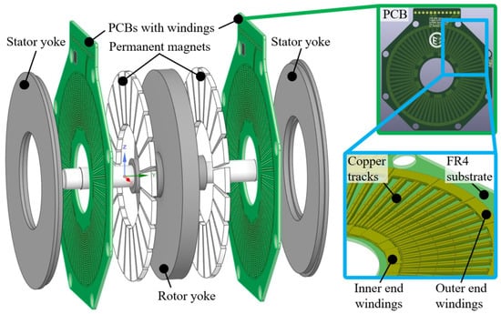
Figure 1.
(Left) Three-dimensional model of a double stator–single rotor axial flux machine with PCB winding. (Upper right) Front view of the PCB with wave windings. (Bottom right) Three-dimensional view of inner structure and track arrangement with layer stack of PCB segment.
Eddy current losses lead to additional joule heating of the windings, which lowers the achievable current-carrying capacity at given maximum temperature constraints. They also cause a breaking torque that decreases the propulsion torque of the electrical machine, which has to be compensated by a larger machine current. The heating of the PCB must be handled with care to ensure its mechanical integrity. The glass transition temperature of the typical PCB substrate FR4 is [3] and reaches up to in the case of high-temperature boards [4], where the operating temperature is recommended to be lower [4]. That is why it is important to consider the eddy current losses from the beginning of the design process of axial machines with PCB windings located in an air gap.
Typically, the thin copper sheets of a PCB have a thickness ranging from to [5]. Unlike round wire windings, the cross-section of the tracks can be varied locally and adapted to specific design constraints [6]. Apart from magnetic flux density and frequency, track width has a strong influence on eddy current losses. Additionally, joule heating due to eddy current losses has to be taken into account by an appropriate cooling design [7].
In the first design stage, thousands of different samples with several design parameters and constraints need to be evaluated to explore the design space. This requires sizing equations that are calculated within a short amount of time. Often, the design process of electric machines starts with more or less coarse analytical calculated predesigns and determines the eddy current losses by performing finite element analysis (FEA) with the chosen design in a second step, where FEA is very time-consuming. To accelerate the design process, (semi-) analytical expressions for determining the eddy current losses are crucial. There are some approximations that exist, mostly for radial flux machines, but there is no comparison between them regarding accuracy and time consumption to find the most appropriate one. In the table below, a comprehensive overview of different analytical calculation techniques to evaluate the eddy current losses is provided. These techniques were adapted to the conditions of slotless axial flux machines with air gap windings. Methods M3, M7, and M8 originate from different parts of electrical machines, which were transferred to tracks of PCB windings in slotless axial flux machines. Table 1 presents a brief overview of the calculation techniques, their origin, the basic approach, and the handling of normal/axial and tangential components of the spatial magnetic flux density vector and their harmonic content. The results were compared to FEA regarding accuracy and time consumption. The focus is on ironless/slotless windings with a rectangular cross-sectional shape. Eddy current loss equations for round wires can be found in [2,8,9]. These techniques can be used for PCBs where the tracks are augmented with round wire welded onto a track [10].

Table 1.
Overview of different eddy current loss calculation methods and their respective assumptions.
Some of the presented techniques are also applicable to eddy current loss evaluation in permanent magnets or to slotted machine designs if the magnetic flux density at each location of the conductors in the slot is known. If the copper tracks are placed in slots, they are shielded from the air gap field. In the case of straight slot openings, the air gap field penetrates the tracks located close to the air gap. Even through air gap flux density drops significantly over the slot openings, the eddy current losses in the affected conductors cannot be neglected. Slotted designs also have a magnetic slot stray field caused by the slot conductor currents themselves, which generate eddy current losses. This is typical, e.g., for hairpin windings [11,12,13,14,15], but this is not within the scope of this paper.
2. Eddy Current Loss Calculation Techniques
2.1. Prerequisites
In the case of rotating instead of alternating flux density, the magnetic flux density is split into an axial and a tangential component, each represented by Fourier series coefficients, and they can be evaluated, e.g., using the method in [16] or finite element analysis. If not explicitly stated, calculation techniques only consider the axial flux density component. Current-carrying conductors only generate torque when they are close to the vertices of the magnetic flux density. However, eddy current losses are primarily generated when the conductors are close to the pole change domain. Thus, the current controller injects the phase current when the conductor is close to the center of the magnet, and the phase current is close to zero when the conductor is close to the pole change domain. That is why joule losses due to phase current and eddy current losses do not appear simultaneously. Eddy current losses can therefore be determined independently. In axial flux machines, a radial dependency of the magnetic flux density can occur, particularly when there is a large effective air gap and a small outer-to-inner radius ratio. Eddy current losses have to be evaluated piecewise by considering the corresponding magnetic flux density. Compared to the penetration depth, the tracks in PCB motors are so thin that current displacement can be neglected. It will be assumed that there is no repercussion on the excited magnetic field due to the eddy currents. According to [17], the specific electrical conductivity of copper depends on its temperature according to (1), where the specific electrical conductivity of copper at corresponds to and to approximately .
2.2. Method 1
In [17], the specific eddy current losses of an electrical steel sheet are determined based on a given sheet thickness and infinite in-plane dimensions. This result can be carried over to rectangular conductors by equating the sheet thickness with the conductor width and integrating the eddy current losses over the conductor thickness . This leads to (2)–(4), where considers the harmonic content of the magnetic flux density and refers to rotating magnetic flux density with an axial and a tangential component.
For axial flux motors, the conductor length is then according to (5):
2.3. Method 2
The calculation technique (6) with (7) according [18] is also based on the eddy current loss determination of electrical steel sheets. Ref. [18] assumes that the magnetic flux density vector is parallel to the sheet plane where the sheet has an infinite in-plane dimension and the magnetic flux density vector is homogeneously distributed and only changes with time.
The eddy currents cause a magnetic field that dampens the excited one. This leads to a different eddy current distribution depending on the sheet thickness and penetration depth. That is why the author of [18] differentiates between thin and thick sheets based on the sheet thickness-to-penetration depth ratio to simplify (6). According to [18], a thin sheet is approximately entirely penetrated by eddy currents when ; thus, (6) becomes (8).
and (6) becomes (9) for thick sheets if [18].
2.4. Method 3
Some electrical pump drives use canned motors. The can is located in the air gap, where the can hermetically seals the conveyed fluid from the stator and the rotor is in touch with the fluid. The can is a thin-walled sleeve made of non-magnetic steel, like Hastelloy C and Austenite 1.4571 [19]. Due to the specific electrical conductivity of these steels (, [19]), eddy current losses cannot be neglected. The specific eddy current losses in the can are determined separately for each harmonic wave [20] by calculating (10) and (11).
Unlike a track, a can forms a consistent conductor in the peripheral direction, where the integral of the current density in the peripheral direction is a zero mean. Similarly to [21], the eddy current density is also the zero mean over the cross-section of the track. Thus, (10) has to be adapted so that only the AC component of the magnetic flux density in the conductor has an effect on instantaneous eddy current losses. As such, (10) becomes (12) with (11), where corresponds to the rotor position.
To receive the average eddy current losses, the instantaneous eddy current losses have to be averaged over a rotational period of the rotor, where the eddy current losses of each harmonic wave are summed up (13).
2.5. Method 4
So-called surface losses can appear in the rotors of induction machines, caused by electrical bridges between the edges of electrical steel sheets after stamping and stacking [18]. These bridges are forming a conductor tangential to the rotor surface. Due to the slotted stator, the magnetic air gap flux density drops over the slot openings, which causes slot-frequent magnetic flux density waves. It is assumed that these pulsating magnetic flux density waves penetrate the rotor tangential to the rotor surface, where the equivalent sheet thickness is . The resulting frequency can be calculated according to (15).
It has to be considered that for , ref. [18] uses a value between 0.08 and 0.13, which was evaluated in experiments by Richter for a iron sheet of type IV. Also, this calculation technique is based on the thick-sheet approximation introduced in Section 2.3, and the eddy current losses are proportional to instead of .
2.6. Method 5
In [2], rotational magnetic air gap flux density is considered and split into an axial and tangential component, and , respectively. Either the eddy current losses (19) are evaluated for each harmonic wave and then summed up or the eddy current losses are first evaluated for the fundamental wave according to (20) and then corrected by the distortion factor in (21) [2].
These expressions are valid for rectangular conductors. In the case of slotless windings made of round wire, (22) can be applied [2].
2.7. Method 6
The technique applied in [8] first calculates the magnetic field distribution using FEA and then determines the eddy current losses for each single conductor through a hybrid analytical expression. This technique is independent of slotted or non-slotted electrical machine design. An expression for rectangular conductors and round wire is given in (23) and (24), respectively [8].
2.8. Method 7
Similarly to [19,22], a track can be virtually divided into N strips, each represented by an ohmic resistance (see Figure 2), where [22] uses parameters based on [23]. Tangential currents between adjacent strips are neglected. Within each strip, an electromotive force (EMF) is induced, which can be described by a complex voltage phasor according to (25) and (26).
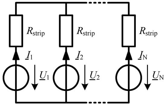
Figure 2.
Equivalent circuit of track strip model.
The ohmic resistance of a single strip is given in (27).
Each single strip current can be calculated using mesh current analysis or superposition according to Helmholtz. In the case of two strips, the eddy current losses result in (28).
In the case of more than two strips, a fictive current for each single strip is determined first, as shown in Figure 3. All voltage sources, except the EMF of the corresponding strip, are masked out, and the corresponding fictive current is calculated according to (29).
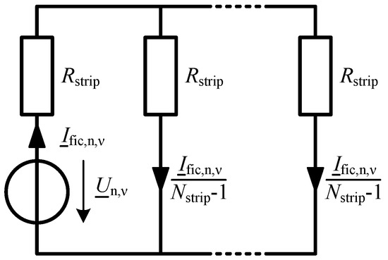
Figure 3.
Equivalent circuit for superposition according to Helmholtz.
2.9. Method 8
In surface-mounted permanent magnet machines, slot-frequent harmonic flux density waves also cause eddy current losses depending on the specific conductivity of the permanent magnet material. Ref. [24] applied a technique to a permanent magnet motor with concentrated windings by solving two-dimensional partial equations. So, the eddy current losses for each single harmonic wave can be calculated according to (32), in which has to be applied with respect to the relative movement and direction of the harmonic wave. describes the reduction in eddy currents, as their circular trajectory close to the magnet ends in a radial direction [24].
2.10. Method 9
According to the law of conservation of energy, eddy current losses are equal to the mechanical braking power affecting the conductor. Each time a conductor moves relatively through a pole change domain, a braking torque pulse is generated by eddy currents. The instantaneous torque can be calculated according to (36) at the mean radius (39) by applying Parseval’s theorem, where complex Fourier series coefficients describe the magnetic air gap flux density distribution along the entire mechanical circumference [21]. The related equations were adapted to a fixed track position and moving axial magnetic flux density. represents the complex Fourier series coefficients of the rotor in the starting position and is the mechanical instantaneous rotor angle according to (37) and (38). The effect of the track width is described by (40).
Subsequently, the instantaneous eddy current losses have to be averaged to obtain the average eddy current losses and are then multiplied by the total number of conductors. This technique considers an arbitrary harmonic content in the magnetic flux density without accepting calculation errors by handling each harmonic separately.
2.11. Method 10
For round wire winding [9], the eddy current loss density was determined according to (41) for each harmonic flux density wave and then integrated along the wire.
3. Benchmarking/Comparison of Calculation Results
The semi-analytical eddy current loss calculation techniques presented above were compared to FEA results from Ansys Maxwell regarding computation time consumption and calculation error. The specimen used was a slotless axial flux machine with surface-mounted permanent magnets, where the magnets had a rectangular cross-sectional shape. A single radially arranged copper track was located in the center of the PCB and had a constant width in the radial direction, with the PCB and the stator yoke being separated by the thickness of the thermal interface material (TIM). The FEA model in Figure 4 shows a segment where the magnetic field is periodically continued circumferentially by defining independent and dependent boundary planes. This model is based on the axial flux machine shown in Figure 1. Based on previous studies, it is assumed that the repercussion of the eddy currents in the conducting tracks of the PCB winding on the excited field is too low and was neglected. The objective of the eddy current loss techniques is to calculate the losses for a single track and then scale them up for the entire PCB winding.
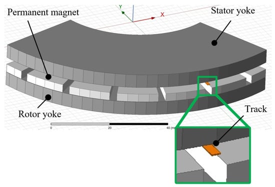
Figure 4.
Partial FEA model of axial flux machine in Ansys Maxwell.
The rotor had 22 poles and rotated at different speeds from 0 to , so the electrical fundamental frequency ranged from 0 to . The eddy current losses were determined at a track temperature of .
The semi-analytical eddy current loss calculation techniques were fed with the axial and tangential magnetic flux density distribution Fourier series amplitudes, determined by FEA. The axial and tangential components of the magnetic flux density distribution in the circumferential direction at the mean radius are shown in Figure 5. The tangential magnetic flux density was considered in the corresponding methods 1, 5, and 6.
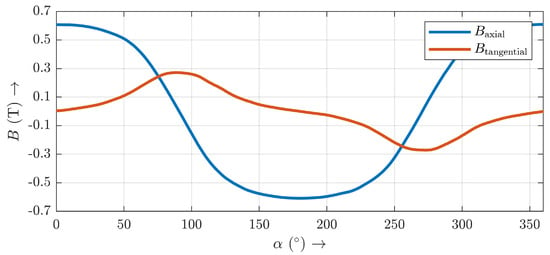
Figure 5.
Axial and tangential magnetic flux density distribution on mean radius in the middle of the PCB from FEA.
Magnetic flux density varies depending on the radius (see Figure 6 and Figure 7), so the semi-analytical calculations were performed piecewise from the inner to the outer radius in six pieces. If the radial variation of the axial magnetic flux density is neglected, the calculation error will be larger.
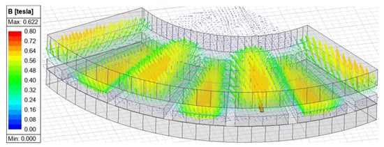
Figure 6.
Vectorial magnetic flux density distribution at the center plane of the PCB.
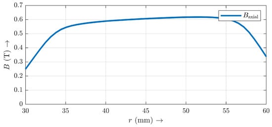
Figure 7.
Axial magnetic flux density in the center of a north pole in the radial direction between the inner and outer radius in the middle of the PCB from FEA.
Because eddy current losses strongly depend on track width, this was varied from to . The resulting eddy current losses depending on speed and track width are shown in Figure 8. The parameters of the device under test are summarized in Table 2. The time consumption and accuracy of the analytical computations were compared against a finite element simulation; the results are shown in Table 3 and Table 4. The computations were carried out on a high-performance computer whose specifications are listed in Table 5.
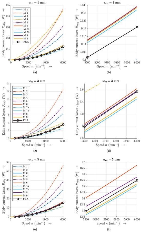
Figure 8.
Comparison of eddy current losses. (a,c,e) Full views. (b,d,f) Zoomed views for different track widths. Note that results of method M3 are almost same as M9, and the lines lie on top of one another.

Table 2.
Parameters of the evaluated axial flux machine specimen.

Table 3.
Time consumption of the various calculation techniques.

Table 4.
Absolute and relative error of calculation technique compared to FEA depending on speed.

Table 5.
Specifications of the high-performance computer used in the study.
4. Conclusions
For the design space exploration of slotless axial flux machines with PCB air gap windings, it is crucial to calculate eddy current losses to ensure the thermal and mechanical integrity of the PCB winding. The thermal limit defines the current-carrying capability and thus the machine performance and utilization. Finite element analysis is known to deliver the most accurate results when designing electric machines, but it is the most time-consuming technique. There are various eddy current loss calculation methods for different machine parts, but not all of them can be applied directly to axial flux machines without modification. The most accurate and fastest method was sought and its validity checked to accelerate design space exploration with thousands of samples where accuracy is less essential than fast computations. PCB windings of slotless axial flux machines are planar and have a rectangular cross-sectional shape instead of a circular one with round wire windings. A comprehensive overview of analytical calculation techniques was presented, in which the methods were adapted to slotless axial flux machines. Time consumption and accuracy were compared to finite element simulation. Originally based on radial flux canned motors, methods M3 and M7 were reworked because the winding tracks are not a consistent conductor in theperipheral direction and are limited by their edges.
In general, the accuracy of approximations depend on the neglect of the underlying modeling, as stated in Section 2.1 and the applied discretization. Inter alia, the attenuating effect on the excitation field is neglected.
The methods M1, M2, M4, and M5, which are based on eddy current loss calculations for electrical steel sheets, were significantly overestimated and had the worst errors compared to the values evaluated through FEA. According to [2] and Table 1, method M5 is said to be applicable for air gap windings, but the approach is similar to electrical steel sheets. It must be noted that the steel sheet-based methods assume that the magnetic flux density vector is oriented parallel to the sheet and the magnetic flux density is distributed homogeneously along the steel sheet with a linear current density distribution from the center to the sheet edge, which is in fact not the case for slotless windings. In the case of slotless axial flux machines, the axial magnetic flux density is perpendicular to the stator surface, leading to a different eddy current density distribution. Method M4 has the weighting factor that is determined by experiments with steel sheets, but copper has a higher electrical conductivity and much lower magnetic permeability compared to electrical steel, which affects the penetration depth. In method M4, the exponent of the magnetic flux density and the frequency is 1.5 instead of 2, which leads to a further deviation. Therefore, the steel sheet-based methods are considered to be not applicable.
The track strip model of method M7, with only two strips according to (28), underestimated the eddy current losses. With a higher number of strips and thus a finer discretization, the accuracy was significantly improved. The results from the methods M3, M6, M7, M8, and M9 are very close together, with M8 being the closest to FEA in the case of larger track width and where M3 and M9 gain almost same results.
The eddy current losses are proportional to the squared magnetic flux density. But if you take the monomials of the Fourier series of the magnetic flux density as a vector, the squaring results in the dyadic product instead of the scalar product. Thus, an error occurs if you calculate each order of the Fourier series separately. Furthermore, it should be mentioned that the spatial vectors of the magnetic flux density do not only consist of the axial components. Therefore, methods M1, M5, and M6 consider a tangential magnetic flux density component. The mentioned inadequacies of the modeling of eddy current loss points are considered to cause the error depending on the track width. However, the absolute errors of M3, M6, M7 (with a sufficient number of strips), M8, and M9 are small enough to be acceptable for design space exploration.
Method M6 had the fastest computation time (0.5 ms) and M9 the worst (7573.48 ms), with rotor position discretization having a significant impact on the computation time of M9. Even if method M5 is slightly faster than M6, the calculation error of M5 is very large. For the reasons mentioned, method M8 is considered to have the best trade-off between accuracy and time consumption. Therefore, method 8 is recommended for the early-stage design of slotless axial flux machines.
Author Contributions
Conceptualization, A.B.; methodology, A.B.; software, D.D. and A.B.; validation, A.B., D.D. and S.U.; formal analysis, A.B. and D.D.; investigation, A.B. and D.D.; resources, S.U.; data curation, A.B. and D.D.; writing—original draft preparation, A.B.; writing—review and editing, A.B., D.D. and S.U.; visualization, D.D. and A.B.; supervision, A.B.; project administration, A.B. and S.U.; funding acquisition, S.U. All authors have read and agreed to the published version of the manuscript.
Funding
This research has been funded by the German Federal Ministry of Education and Research (BMBF) under grant number 13FH541KX9.
Data Availability Statement
The raw data supporting the conclusions of this article will be made available by the authors on request.
Acknowledgments
We thank the SEW-EURODRIVE GmbH & Co KG in Bruchsal, Germany, for supporting this project.
Conflicts of Interest
The authors declare no conflicts of interest.
Nomenclature
| Amplitude of magnetic flux density for harmonic | |
| order with respect to fundamental wave | |
| Amplitude of axial component of magnetic flux density of order with respect | |
| to fundamental wave | |
| Amplitude of tangential component of magnetic flux density of order with | |
| respect to fundamental wave | |
| Peak value of magnetic flux density distribution | |
| Remanence magnetic flux density | |
| Complex Fourier series coefficient of magnetic flux density | |
| Round wire diameter | |
| Electrical frequency of fundamental wave | |
| Coercive magnetic field strength of permanent magnet | |
| Adhesive thickness | |
| Copper track thickness | |
| PCB thickness | |
| Permanent magnet thickness | |
| Thickness of thermal interface material | |
| Complex fictive current phasor n-th strip and -th order | |
| Complex strip current phasor n-th strip and -th order | |
| Carter factor of stator and unslotted rotor | |
| Excess factor | |
| Axial stack length of radial flux machine | |
| Copper track length | |
| Mass of conductor | |
| Number of copper tracks | |
| Number of strips | |
| Number of stator slots | |
| Number of rotor slots | |
| n | Rotational speed |
| Synchronous rotational speed | |
| Mean eddy current losses | |
| Mean eddy current losses for a specific harmonic order | |
| Mean eddy current losses for k-th conductor piece | |
| Specific eddy current losses | |
| Equivalent ohmic resistance | |
| Strip ohmic resistance | |
| Mean radius | |
| Inner radius of axial flux machine | |
| Outer radius of axial flux machine | |
| Rotor slot width | |
| Complex RMS voltage phasor of n-th strip and -th order | |
| Induced RMS voltage of a strip | |
| Copper track volume | |
| Copper track width | |
| Temperature coefficient of copper | |
| Angular width of copper track | |
| Angular position of left copper track edge | |
| Angular position of right copper track edge | |
| Pole covering ratio | |
| Factor for describing magnetic flux density due to slotting | |
| Penetration depth | |
| Auxiliary coefficient | |
| Distortion factor | |
| Copper temperature | |
| Glass transition temperature | |
| Permeability of vacuum | |
| Relative permeability | |
| Permanent magnet recoil permeability | |
| Harmonic order | |
| Specific mass density | |
| Specific electrical conductivity | |
| Effective specific electrical conductivity | |
| Pole pitch | |
| Permanent magnet pitch | |
| Rotor slot pitch | |
| Angular copper track pitch | |
| Mechanical angular frequency | |
| Electrical angular frequency | |
| Abbreviation | |
| FEA | Finite Element Analysis |
| PCB | Printed Circuit Board |
| TIM | Thermal Interface Material |
References
- Jumayev, S.; Boynov, K.O.; Paulides, J.J.H.; Lomonova, E.A.; Pyrhönen, J. Slotless PM Machines with Skewed Winding Shapes: 3-D Electromagnetic Semianalytical Model. IEEE Trans. Magn. 2016, 52, 8108212. [Google Scholar] [CrossRef]
- Gieras, J.; Wang, R.; Kamper, M. Axial Flux Permanent Magnet Brushless Machines, 2nd ed.; Springer Science & Business Media: Berlin/Heidelberg, Germany, 2008. [Google Scholar] [CrossRef]
- Multi Circuit Boards Ltd. Material Default Value—FR4. 26 January 2023. Available online: https://www.multi-circuit-boards.eu/fileadmin/user_upload/downloads/leiterplatten_design-hilfe/e_multi_cb_material-standard-values.pdf (accessed on 23 January 2025).
- Multi Circuit Boards Ltd. Basic Design Rules. Available online: https://www.multi-circuit-boards.eu/en/products/printed-circuit-boards/high-tg-pcb.html (accessed on 23 January 2025).
- Multi Circuit Boards Ltd. Basic Design Rules. 16 January 2025. Available online: https://www.multi-circuit-boards.eu/fileadmin/user_upload/downloads/leiterplatten_design-hilfe/Multi-CB-Leiterplatten_Basic-Design-Rules_en.pdf (accessed on 20 January 2025).
- Bauer, A.; Zacher, B.H.; Schumann, C.; Urschel, S. Challenges and Design Aspects of Power Electronically Fed PCB Motor Windings. In Proceedings of the IKMT 2022—13, GMM/ETG-Symposium, Linz, Austria, 14–15 September 2022; pp. 1–6. [Google Scholar]
- Bauer, A.; Zacher, B.H.; Urschel, S.; Schumann, C. Multilayered PCB-Based Axial Flux Motor Windings with Thermal VIAs to Enhance Thermal Utilization. In Proceedings of the IECON 2023—49th Annual Conference of the IEEE Industrial Electronics Society, Singapore, 16–19 October 2023; pp. 1–6. [Google Scholar] [CrossRef]
- Taran, N.; Ionel, D.M.; Rallabandi, V.; Heins, G.; Patterson, D. An Overview of Methods and a New Three-Dimensional FEA and Analytical Hybrid Technique for Calculating AC Winding Losses in PM Machines. IEEE Trans. Ind. Appl. 2021, 57, 352–362. [Google Scholar] [CrossRef]
- Santiago, J.; Oliveira, J.G.; Lundin, J.; Larsson, A.; Bernhoff, H. Losses in axial-flux permanent-magnet coreless flywheel energy storage systems. In Proceedings of the 18th International Conference on Electrical Machines, Vilamoura, Portugal, 6–9 September 2008; pp. 1–5. [Google Scholar] [CrossRef]
- Würth Elektronik GmbH & Co. KG. Design Guide for High Current Solutions with WIRELAID®. Version 1.4. 14 April 2017. Available online: https://datasheet.datasheetarchive.com/originals/crawler/we-online.de/52cd2d3f59e4ab655b2cb67fc4251db9.pdf (accessed on 11 February 2025).
- Gerling, D. Approximate analytical calculation of the skin effect in rectangular wires. In Proceedings of the 2009 International Conference on Electrical Machines and Systems, Tokyo, Japan, 15–18 November 2009; pp. 1–6. [Google Scholar] [CrossRef]
- Oberretl, K. 13 Rules to Minimize Stray Load Losses in Induction Motors. Bulletin Oerlikon 1969, 389/390, 1–12. [Google Scholar]
- Du-Bar, C.; Wallmark, O. Eddy Current Losses in a Hairpin Winding for an Automotive Application. In Proceedings of the XIII International Conference on Electrical Machines (ICEM), Alexandroupoli, Greece, 1–3 September 2018; pp. 710–716. [Google Scholar] [CrossRef]
- Selema, A.; Ibrahim, M.N.; Sergeant, P. Mitigation of High-Frequency Eddy Current Losses in Hairpin Winding Machines. Machines 2022, 10, 328. [Google Scholar] [CrossRef]
- Oberretl, K. Zusätzliche Wirbelstromverluste in Nutenleitern infolge eindringendem Luftspaltfeld. Arch. Für Elektrotechnik 1978, 60, 121–127. [Google Scholar] [CrossRef]
- Hanselman, D. Brushless Permanent Magnet Motor Design, 2nd ed.; Magna Physics Publishing: Lebanon, OH, USA, 2006. [Google Scholar]
- Müller, G.; Vogt, K.; Ponick, B. Berechnung Elektrischer Maschinen, 6th ed.; WILEY-VCH Verlag GmbH & Co. KGaA: Weinheim, Germany, 2008. [Google Scholar] [CrossRef]
- Binder, A. Energy Converter CAD and System Dynamics; Technische Universität Darmstadt: Darmstadt, Germany, 2023; Available online: https://www.etit.tu-darmstadt.de/media/ew/rd/ew_vorlesungen/lv_cad/CAD_Skript_WS23_24.pdf (accessed on 23 January 2025).
- Burkhardt, Y.; Huth, G.; Urschel, S. Eddy current losses in PM canned motors. In Proceedings of the XIX International Conference on Electrical Machines (ICEM), Rome, Italy, 6–8 September 2010; pp. 1–7. [Google Scholar] [CrossRef]
- Burkhardt, Y. Optimierter Entwurf hocheffizienter PM-Spaltrohrmotoren für Pumpenapplikationen; Kaiserslauterer Beiträge zur Antriebstechnik 5; Shaker: Aachen, Germany, 2011; ISBN 9783844004182. [Google Scholar]
- Bauer, A.; Schumann, C.; Urschel, S. Analytical Calculation of Eddy Current related Losses and Parasitic Torque in PCB Windings. In Proceedings of the 2022 International Conference on Electrical Machines (ICEM), Valencia, Spain, 5–8 September 2022; pp. 1750–1756. [Google Scholar] [CrossRef]
- François, G.; Baudart, F.; Dehez, B. Analytical Estimation of Eddy Current Losses in PCB Winding for the Optimal Sizing of PM Slotless Motor. In Proceedings of the 2019 IEEE International Electric Machines & Drives Conference (IEMDC), San Diego, CA, USA, 12–15 May 2019; pp. 862–869. [Google Scholar] [CrossRef]
- François, G.; Baudart, F.; Henrotte, F.; Dehez, B. Numerical Investigation of Eddy Current Losses in Airgap PCB Windings of Slotless BLDC Motors. In Proceedings of the 2018 21st International Conference on Electrical Machines and Systems (ICEMS), Jeju, Republic of Korea, 7–10 October 2018; pp. 2702–2708. [Google Scholar]
- Scheidt, M. Entwurfskriterien Für Permanentmagneterregte Synchronmaschinen in Zahnspulentechnik Unter Besonderer Berücksichtigung der Zusatzverluste; Kaiserslauterer Beiträge zur Antriebstechnik 3; Shaker: Aachen, Germany, 2009; ISBN 9783832283964. [Google Scholar]
Disclaimer/Publisher’s Note: The statements, opinions and data contained in all publications are solely those of the individual author(s) and contributor(s) and not of MDPI and/or the editor(s). MDPI and/or the editor(s) disclaim responsibility for any injury to people or property resulting from any ideas, methods, instructions or products referred to in the content. |
© 2025 by the authors. Licensee MDPI, Basel, Switzerland. This article is an open access article distributed under the terms and conditions of the Creative Commons Attribution (CC BY) license (https://creativecommons.org/licenses/by/4.0/).