1. Introduction
With the rapid development of China’s economy, urban power demand is growing, and the scale of power grids is constantly expanding, increasing requirements for grid transmission capacity and power supply reliability in cities [
1,
2]. Cable lines are advantageous in that they are less affected by the environment, have high safety and reliability, occupy no ground space, and enhance the urban environment, so their proportion in power grids is increasing [
3]. Currently, 220 kV cable lines are extensively employed, and initiatives incorporating 500 kV cables are also being advanced in leading metropolises such as Beijing and Shanghai [
4,
5,
6].
Domestic and international scholars have conducted a series of studies on cable grounding resistance connection, sequence parameter calculation and fault overvoltage. In power systems, when a single-phase grounding fault occurs, the ungrounded phase voltage increases, resulting in an overvoltage [
7]. In a cable system, when a single-phase ground fault occurs, the metal sheath of the cable will be subjected to a continuous frequency overvoltage, which may break down the insulation and pose a risk to the cable system. The literature suggests that the value of the grounding resistance and the grounding method of the metallic sheath affects the overvoltage on the cable [
8,
9,
10]. Ref. [
11] shows that increasing the grounding resistance can effectively limit the ground fault current, and the reduction in fault current can reduce the shock to which electrical equipment is subjected, reducing the risk of damage to the equipment. Ref. [
12] explores the sequence impedance calculation method for power cables and provides testing methods for cable parameters. Ref. [
13] calculates and analyzes the sequence parameters of submarine cables in EMTP, showing the influence of the sheath’s magnetic permeability on the cable line’s sequence impedance parameters. Ref. [
14] proposes a method of calculating and modeling for determining the equivalent impedance and admittance matrices of three-phase single-core cables, and the sequence impedance parameter matrix for single-core cables has also been studied and analyzed by scholars [
15]. Ref. [
16] analyzed the impact of cable sheath grounding methods on sheath currents under normal conditions. Ref. [
17] presents a review on analytical techniques used to calculate induced voltage on the metallic sheath of underground cables and overhead lines. However, these works primarily addressed lower voltage levels or simplified scenarios without systematic analysis of the following critical aspects: grounding resistance connection modes, the impact of connecting cable grounding devices to substations on zero-sequence impedance and overvoltage suppression, especially for 500 kV long-distance cables.
The research object considered for this study is a long 500 kV transmission line cable project in Beijing. This study systematically analyzes the influence of grounding resistance values (0.1–5 Ω), connection modes (with/without substation linkage) and materials (copper vs. steel) on 500 kV cable sequence impedance and fault overvoltage, leveraging ATP-EMTP simulations. In
Section 2, we derive the theoretical framework for asymmetric fault overvoltage and cable sequence parameters.
Section 3 evaluates grounding resistance impacts on impedance, while
Section 4 quantifies overvoltage distribution. In
Section 5, we discuss the conclusions and engineering implications.
2. Unbalanced Fault Overvoltage and Cable Sequence Parameter Calculation Principles
Asymmetrical short-circuit faults are the most common fault forms in transmission lines. When a single-phase or two-phase unbalanced ground fault occurs, the voltage of the non-faulted phase generally increases, and the voltage of the non-fault phase can reach a high value during a single-phase grounding. Under special circumstances, two-phase short circuit grounding can also result in a high power frequency voltage, but the probability is relatively small. Therefore, this discussion focuses only on single-phase grounding faults.
When a single-phase ground fault occurs, the three-phase current and voltage at the fault point are asymmetrical. To calculate the rise in the voltage of the non-fault phase, the symmetrical component method can be used, and analysis can be carried out through the composite sequence network [
18].
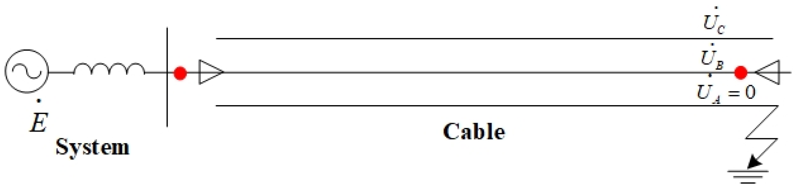
As shown in
Figure 1, the three horizontal lines represent the three phases of the cable and a fault at phase A of the cable. The voltage at healthy phases can be obtained using the composite sequence network:
In Formulas (1) and (2),
,
represents the positive-sequence voltage,
represents the negative-sequence voltage, and
represents the zero-sequence voltage. The sequence current of the fault point
,
,
is expressed as follows:
In Formula (3),
,
, and
represent the positive-sequence, negative-sequence, and zero-sequence input impedances observed from the fault point (with the source electromotive force short-circuited), respectively. The input impedance at the fault point is the sum of the line impedance and the source impedance. By approximating
, the voltage to ground at the fault point M before the fault is
, so Formula (3) can be written as follows:
Correspondingly, there are
Considering the fault point B relative to the ground voltage before the fault
, the following formula can be obtained.
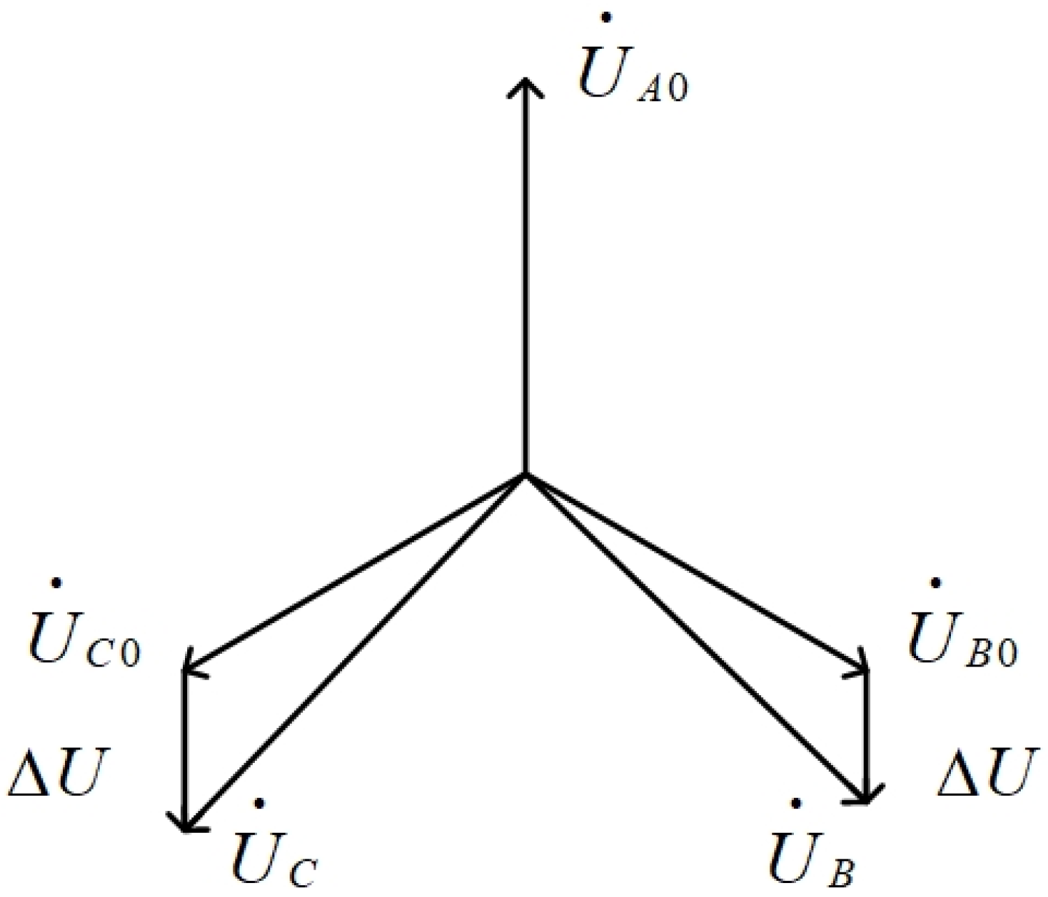
The voltage phasor diagram of single-phase ground fault is shown in
Figure 2. So, we can use the cosine theorem to obtain the non-fault phase voltage value as follows:
is the coefficient of earthing. Substituting Formula (7) into Formula (9), it can be rewritten as follows:
This equation demonstrates that the grounding coefficient is positively correlated with the ratio of zero-sequence impedance to positive-sequence impedance at the fault point. From this theoretical analysis, it can be seen that the magnitude of the fault point overvoltage is related to the ratio of zero-sequence to positive-sequence impedance K. As K increases, the fault point overvoltage also increases.
In accordance with the electromagnetic transient calculation theory for power systems, the sequence impedance of a single-core cable can be analyzed and calculated. The equivalent model is composed of three loops: loop 1 is between the core wire and the return metallic sheath, loop 2 is between the metallic sheath and the outer metallic armor, and loop 3 is between the metallic armor and the ground or seawater.
According to electromagnetic transient calculation theory [
19], the following applies:
The self-impedance in the formula consists of three components: the per-unit-length internal impedance between the core conductor and the metallic sheath, the per-unit-length impedance of the insulation between the core conductor and the metallic sheath, and the per-unit-length internal impedance of the metallic sheath itself. The self-impedances and follow a similar structure.
The coupling impedances and represent the per-unit-length mutual impedances between inner loop 1 and outer loop 2, and between inner loop 2 and outer loop 3, respectively. However, because the current direction is negative, the sign of the coupling impedance is also negative. Since there is no common branch between loops 1 and 3, .
In the EMTP model, the above formulas are not entirely applicable; instead, the voltages and currents of the core conductor and the metallic sheath must replace the loop voltages and currents. Therefore, boundary conditions are introduced to enable this transformation. The boundary conditions are as follows:
In Formula (13),
is the core-to-ground voltage,
is the sheath-to-ground voltage, and
is the armor-to-ground voltage. Substituting the boundary conditions into the formula yields
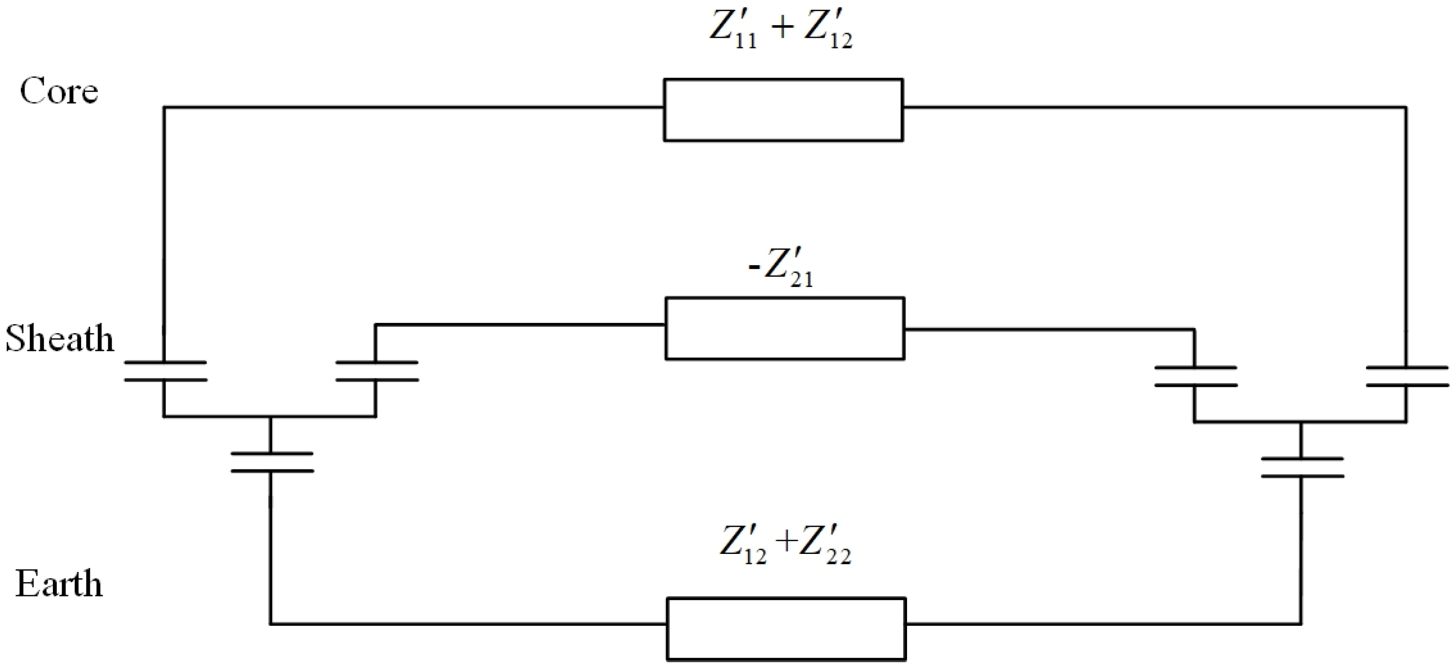
The cable sheath grounding method studied in this article is cross-connected grounding. At this time, the current flowing through the armor layer is very small, so the armor layer can be ignored in the calculation. When the cable armor is not considered, there is
For a single-core cable without armor, it can be represented by the equivalent circuit shown in
Figure 3.
When the sheath is grounded, the effect of the sheath can be eliminated, resulting in the phase matrix for the power cable:
Using the symmetrical component method, a phase-sequence transformation of the above equation yields the sequence impedance parameter matrix for the cable as follows [
20]:
In the above formula,
S is equal as follows:
3. The Impact of Grounding Resistance on Cable Sequence Impedance
The 500 kV transmission and transformation project in Beijing is a pure cable line project, in which the 500 kV power system is connected to substations A and B through 38.6 km long cables. Each cable line is equipped with a 240 MVar high-voltage shunt reactor at both ends. The low-voltage sides of both substations are connected to the 500 kV grid. The equivalent diagram of this transmission project is shown in
Figure 4. In the simulation model, substations A and B are both converted to the 500 kV side. The power system voltage and the voltage of substation are set to 550 kV, considering the most stringent conditions.
The cable type used in the transmission project is ZC-YJLW02-Z-290/500 kV-1 × 2500 mm
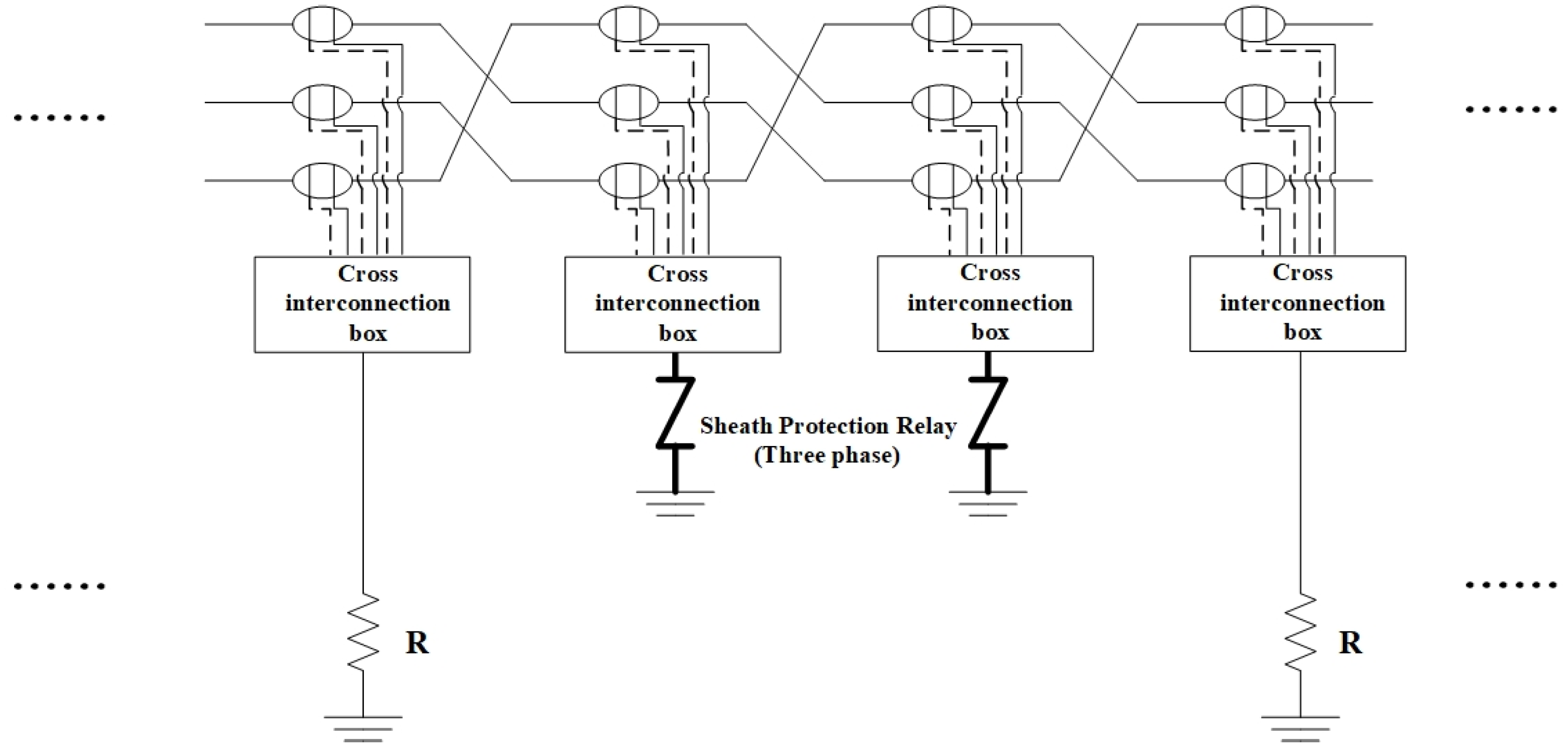
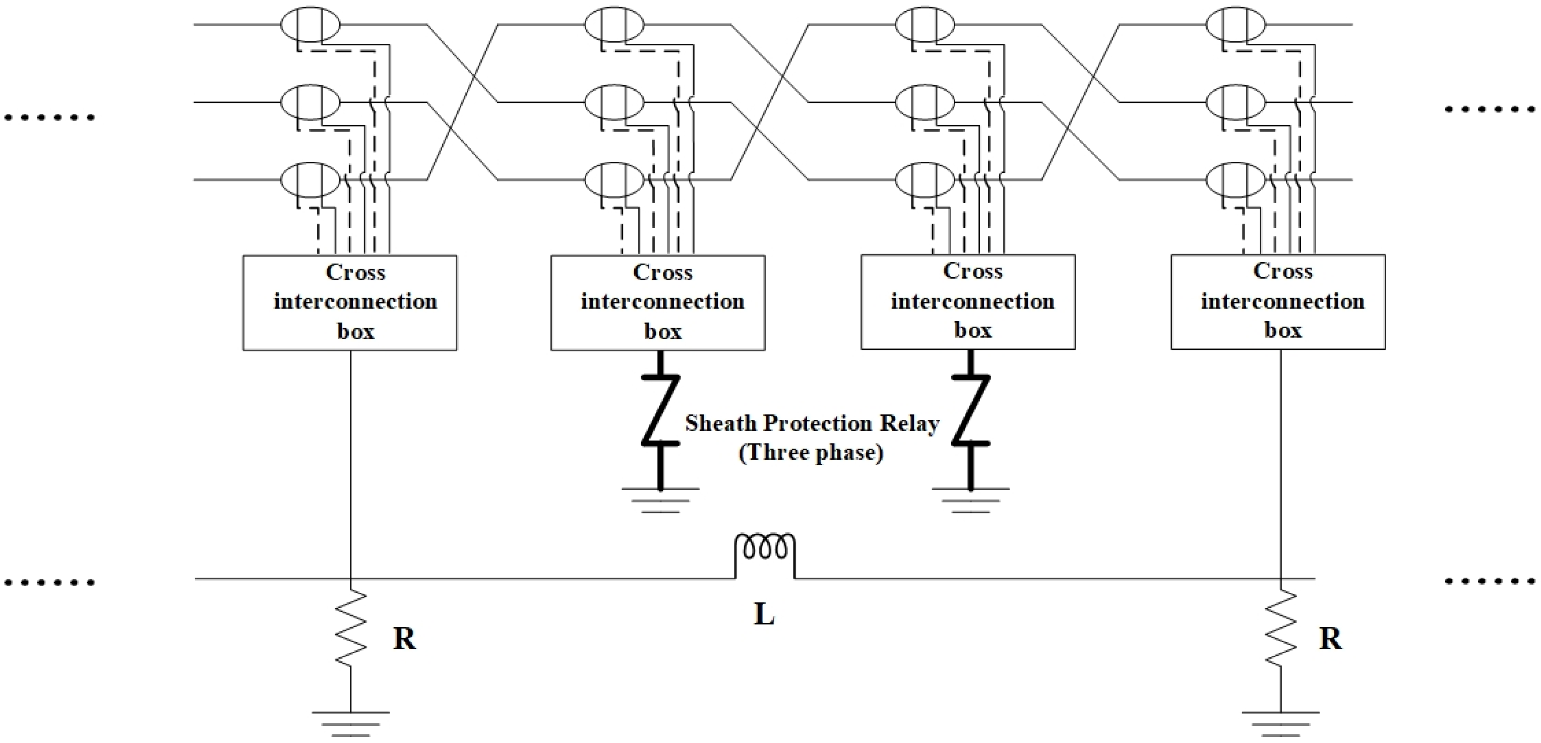
2, and the total length of a single cable is 38.16 km. The cable is grounded by cross interconnection. The cable undergoes a cross-bonding transposition every 530 m, and the cross-interconnection sections are set to 1590 m. There are 24 cross interconnection sections in the whole line. The grounding resistance connection method is shown in
Figure 5; the midpoint of each cross-bonded segment is grounded via a cross-interconnection and a sheath protector while both sides of cross-interconnection are grounded via a cross-interconnection box and grounding resistance. Under normal circumstances, the sheath protector will not operate, which is equivalent to an open circuit. Therefore, its modeling can be omitted. In
Figure 5, R represents the grounding resistance. In subsequent simulations and calculations, the value of grounding resistance mentioned refers to the resistance value of a single grounding resistor.
The simulation model of this project is established in ATP-EMTP. The main modules of the modeling include substations on both sides, cable lines, shunt reactors, lightning arresters, and grounding resistors. The substation model is simulated by an AC power supply with internal resistance and an equivalent 550 kV busbar. The cable line is simulated by an LCC module. The length of a single LCC module is set to 530 m. Each cable cross-interconnection section consists of three LCC modules (the LCC modules are connected by transposition modules). A single cable consists of 24 cross-interconnection sections. Grounding resistors are connected on both sides of each cross-interconnection section, and the three-phase sheath is led out and then connected to a single-phase resistor. Shunt reactors are connected on both sides of the cable and simulated with inductance elements. The simulation time is set to 1 s, and the simulation step size is set to 1 microsecond.
To study the relationship between grounding resistance and power frequency overvoltage during cable faults, this paper selects the operating condition with the most severe fault overvoltage as the typical scenario for analysis. Specifically, this is the scenario where only Cable II is in operation, and a single-phase-to-ground fault with load rejection occurs on substation B. After experiencing a single-phase-to-ground fault with load rejection on substation B, the circuit breaker on the B-side trips, and the sequence impedance between the system and the fault point is the sum of the cable impedance and the system-side impedance.
From the theoretical analysis above, it is known that the magnitude of the power frequency overvoltage at the fault point is related to the ratio of the zero-sequence to positive-sequence input impedance from the system to the fault point, which specifically depends on the zero-sequence and positive-sequence impedances of the cable line and the positive-sequence and zero-sequence impedances of the system source. The impact of grounding resistance on the cable sequence impedance parameters can reflect the effect of grounding resistance on the frequency overvoltage at the fault point of the cable. The system’s positive-sequence and zero-sequence impedances are known, while the sequence impedance of the cable must be determined based on the structural parameters of the cable.
In EMTP, the cable support program cannot directly obtain the sequence parameters of the cable line. However, its series impedance can be derived using methods such as the short-circuit test method, the reduced matrix method, or formula estimation [
21]. This paper uses the short-circuit test method to calculate the sequence parameters of the cable line: in EMTP, the cable end is grounded, and a unit positive-sequence or zero-sequence current source is applied at the cable head. The voltage measured at the cable head represents the positive-sequence impedance and zero-sequence impedance of the cable.
For the selection of grounding resistance, according to the State Grid Corporation of China’s enterprise standard Q/GDW 11316-2018 ‘Test code for HV power cables’ [
22], the grounding resistance of tunnel grounding devices should not exceed 5 Ω, and the overall grounding resistance should not exceed 1 Ω. Therefore, the maximum grounding resistance value for calculation is selected as 5 Ω.
There are various examples of cable grounding resistance measurements using the three-electrode method [
23]. For a 300 m cable in a mined tunnel, the grounding resistance was approximately 35 mΩ. When the current and voltage electrode lines were swapped, the measured grounding resistance was about 35.6 mΩ. For a 5 km long-distance cable, the grounding resistance measured using the same method was around 57 mΩ, and swapping the current and voltage electrode lines yielded a grounding resistance of approximately 57.5 mΩ. Since the actual measured grounding resistance value of the tunnel is often smaller, 0.1 Ω is selected as the minimum value for the chosen grounding resistance.
Based on the examples of grounding resistance measurements and the relevant provisions in the standards mentioned above, in this paper, the grounding resistance of the cable is varied from 0.1 Ω to a maximum of 5 Ω. The sequence impedance of the cable under different grounding resistances is measured using the short-circuit test method, and the test results are summarized in the table below. In this case, the grounding resistance is assumed to be the same along the entire length of the cable.
The calculated data in
Table 1 are of the same order of magnitude as the theoretical calculation and analysis results in references [
12,
20,
21].
Table 1 shows that when the grounding resistance along the entire length of the cable is the same, the magnitude of the grounding resistance does not affect the cable’s positive-sequence impedance. However, the cable’s zero-sequence resistance and zero-sequence inductance both increase with the increase in grounding resistance. When the grounding resistance reaches 5 Ω, the cable’s zero-sequence impedance reaches its maximum value.
The above analysis considers the situation where the grounding devices at both ends of the cable are not connected to the substations at both ends. According to the national standard GB/T 50065-2011 ‘Grounding Design Code for AC Electrical Installations’ [
24], the grounding resistance for large current grounding systems at the substation side should be no greater than 0.5 Ω. Considering the case where the cable’s grounding devices at both ends are directly connected to the substation side, the grounding resistance at the cable’s head and tail is taken as 0.5 Ω.
To verify the impact of this factor on the cable sequence parameters, we set the grounding resistance at both ends of the cable to 0.5 Ω to indicate that both ends of the cable are connected to the substation, and change the other grounding resistance from 0.1 Ω to a maximum of 5 Ω. Then, we remeasured the cable sequence parameters under different grounding resistances, and the results are listed in
Table 2.
From the calculation results in the table, it can be observed that whether the grounding devices at both ends of the cable are connected to the substation does not affect the cable’s positive-sequence parameters, but has a significant impact on the cable’s zero-sequence parameters. Tunnel grounding resistances represent the other grounding resistance except the grounding resistance at both ends of the cable. By comparing this with the data in
Table 1, it can be seen that when the tunnel grounding resistance is less than 0.5 Ω, connecting the grounding resistance at both ends of the cable to substation increases the cable’s zero-sequence impedance.
However, when the tunnel grounding resistance is greater than 0.5 Ω, connecting the grounding resistance at both ends of the cable to substation causes a significant decrease in the cable’s zero-sequence parameters. Additionally, it can be observed that the cable’s zero-sequence inductance increases as the tunnel grounding resistance increases, while the zero-sequence resistance decreases with the increase in tunnel grounding resistance.
The above analysis considers the cable’s grounding resistance as a single grounding resistance value, without accounting for the conductive impedance between the grounding resistances of long grounding bodies. When the conductive impedance of long grounding bodies is considered, the cable’s grounding resistance connection is shown in
Figure 6. In the simulation model, it can be achieved by adding an inductive impedance between the grounding resistance.
Currently, the most common grounding conductor materials used worldwide are copper and steel [
25]. In this paper, copper and steel are selected as the materials for the grounding body, and a comparison is made of the cable’s sequence impedance parameters when different grounding materials are used. In the simulation, the conductive impedance inductance value for the copper grounding body is considered as 0.157 mH/km, while for the steel grounding body, the conductive impedance inductance is considered to be 100 times that of copper.
When considering the conductive impedance, we used the short-circuit current test method to measure cable sequence impedance with different grounding materials, and the results are listed in the table.
The table further delves into the impact of grounding resistance values at the cable’s endpoints on its sequence impedance, taking into account the conductive impedance. Specifically, the scenario labeled “0.5 Ω at both ends” signifies that the grounding resistance at both cable terminations was set to 0.5 Ω, while the terminal grounding resistance was set to 5 Ω.
The data in
Table 3 indicate that the positive-sequence parameters of the cable are not significantly affected by the two factors listed in the table. In the case where the grounding system at both ends of the cable is not connected to the substation and the contact impedance is considered, the material of the grounding electrode has a significant impact on the cable’s zero-sequence impedance. The zero-sequence impedance of the cable is smaller when using a copper grounding electrode compared to a steel grounding electrode. When using a steel grounding electrode, the cable’s zero-sequence impedance parameters are close to those obtained without considering the contact impedance.
In this case, the cable’s zero-sequence impedance is mainly influenced by the material of the grounding electrode. When the grounding system at both ends of the cable is connected to the substation, the effect of considering the contact impedance on the cable’s zero-sequence impedance is not obvious. The zero-sequence resistance of the cable with a copper grounding electrode is lower than that with a steel grounding electrode, while the zero-sequence inductance of the cable with a copper grounding electrode is higher than that with a steel grounding electrode.
4. The Impact of Grounding Resistance on Cable Fault Overvoltage
Based on the previous analysis, it is clear that the value and connection method of the cable’s grounding resistance affect the ratio of zero-sequence impedance to positive-sequence impedance, which in turn influences the overvoltage at the fault point during a single-phase-to-ground fault with load rejection.
Next, the impact of grounding resistance on the distribution of overvoltage along the cable line is studied. The connection point between the cable and substation B is taken as the cable’s head, and the voltage measurement point 1 is set at the cable head. Voltage measurement points are placed every 9.54 km along the cable, resulting in a total of five voltage measurement points along the cable.
When considering the cable’s tunnel grounding resistance as 5 Ω, and the grounding resistance at both ends as 0.5 Ω, a simulation is conducted using the ATP-EMTP 6.0 to analyze the overvoltage along the cable line under the condition of a single-phase-to-ground fault with load rejection on the B-side of the substation. The simulation results for the cable’s overvoltage along the line are included in
Table 4 for three cases: (1) without considering conductive impedance, (2) considering conductive impedance with a copper grounding body, and (3) considering conductive impedance with a steel grounding body.
When the grounding resistance of the entire cable line is considered to be 5, the above three situations are simulated and analyzed, and the voltage results along the line are listed in
Table 5.
In
Table 4 and
Table 5, 1.0 p.u. represents 449.073 kV, which equals to
kV. According to the discussion of cable sequence impedance parameters, grounding coefficient and K in
Section 2 and
Section 3, when the grounding conductor is a copper conductor, the K value calculated theoretically is 2.44, and the corresponding grounding coefficient is 1.196, which is consistent with the simulation result of measuring point 1. When the grounding conductor is a steel conductor, the K value calculated theoretically is 4.7, and the corresponding grounding coefficient is 1.36, which is consistent with the simulation result of measuring point 1. The overvoltage data at the fault point in different scenarios in
Table 4 align with the previous analysis of the cable’s sequence impedance parameters. The data show that when the cable experiences a single-phase-to-ground fault with load rejection, the power frequency overvoltage along the cable decreases as the distance from the fault point increases. However, the change in overvoltage along the cable is not very pronounced, while the voltage drop at the cable’s head and tail ends is more significant. By comparing the data in
Table 4 and
Table 5, we can find that whether the grounding devices at both ends of the cable are connected to the substation has a great influence on the overvoltage along the line. Connecting the grounding devices at both ends of the cable to the substation can effectively suppress overvoltage along the line. The results in
Table 4 and
Table 5 can also verify the influence of cable sequence parameters on the overvoltage at the cable fault point, and the influence law is consistent with the previous theoretical analysis.


