
Carbon Dot-Modulated Phase-Change Composites for Wide Temperature Range and High-Density Heat Storage and Release

Abstract
1. Introduction
2. Experimental Section
3. Results and Discussion
4. Conclusions
Supplementary Materials
Author Contributions
Funding
Data Availability Statement
Acknowledgments
Conflicts of Interest
References
- Xiong, Q.A.; Alshehri, H.M.; Monfaredi, R.; Tayebi, T.; Majdoub, F.; Hajjar, A.; Delpisheh, M.; Izadi, M. Application of phase change material in improving trombe wall efficiency: An up-to-date and comprehensive overview. Energy Build. 2022, 258, 111824. [Google Scholar] [CrossRef]
- Junaid, M.F.; Rehman, Z.U.; Ijaz, N.; Cekon, M.; Curpek, J.; Elhag, A.B. Biobased phase change materials from a perspective of recycling, resources conservation and green buildings. Energy Build. 2022, 270, 112280. [Google Scholar] [CrossRef]
- Ge, H.S.; Li, H.Y.; Mei, S.F.; Liu, J. Low melting point liquid metal as a new class of phase change material: An emerging frontier in energy area. Renew. Sust. Energy Rev. 2013, 21, 331–346. [Google Scholar] [CrossRef]
- Zhang, B.P.; Chen, Y.; Mu, Y.; Yang, B.Z.; Li, X.; Ke, S.R.; Min, X.; Mi, R.Y.; Wu, X.W.; Liu, Y.G.; et al. A novel cobalt-reinforced graphene aerogel composite phase change material with excellent energy storage capacity for low-temperature industrial waste heat recovery. J. Energy Storage 2025, 107, 114920. [Google Scholar] [CrossRef]
- Lu, Y.; Xiao, X.D.; Fu, J.; Huan, C.M.; Qi, S.; Zhan, Y.J.; Zhu, Y.Q.; Xu, G. Novel smart textile with phase change materials encapsulated core-sheath structure fabricated by coaxial electrospinning. Chem. Eng. J. 2019, 355, 532–539. [Google Scholar] [CrossRef]
- Zhang, H.J.; Zhang, X.G.; Pan, D.; Ai, Y.H.; Chen, Y.S. Preparation and application of high-temperature composite phase change materials. J. Energy Storage 2023, 68, 107669. [Google Scholar] [CrossRef]
- Li, X.; Liu, Y.; Xu, Y.; Tao, P.; Deng, T. Solid–Liquid Phase Change Composite Materials for Direct Solar–Thermal Energy Harvesting and Storage. Acc. Mater. Res. 2023, 4, 484–495. [Google Scholar] [CrossRef]
- Tao, J.L.; Luan, J.D.; Liu, Y.; Qu, D.Y.; Yan, Z.; Ke, X. Technology development and application prospects of organic-based phase change materials: An overview. Renew. Sust. Energ. Rev. 2022, 159, 112175. [Google Scholar] [CrossRef]
- Wang, P.; Diao, X.M.; Chen, X. Intelligent phase change materials for long-duration thermal energy storage. Mater 2024, 7, 2716–2718. [Google Scholar] [CrossRef]
- Vitorino, N.; Abrantes, J.C.C.; Frade, J.R. Quality criteria for phase change materials selection. Energy Convers. Manag. 2016, 124, 598–606. [Google Scholar] [CrossRef]
- Qiao, Y.J.; Gu, X.; Gao, Z.Y.; Bai, C.Y.; Zhang, L.L.; Wang, X.D.; Zheng, T. Preparation and characterization of eicosane-paraffin/expanded graphite/polyurethane as form-stable composite phase change materials with wide phase change temperature range. Mater. Lett. 2024, 366, 136518. [Google Scholar] [CrossRef]
- Shamseddine, I.; Pennec, F.; Biwole, P.; Fardoun, F. Supercooling of phase change materials: A review. Renew. Sust. Energ. Rev. 2022, 158, 112172. [Google Scholar] [CrossRef]
- Safari, A.; Saidur, R.; Sulaiman, F.A.; Xu, Y.; Dong, J. A review on supercooling of Phase Change Materials in thermal energy storage systems. Renew. Sust. Energ. Rev. 2017, 70, 905–919. [Google Scholar] [CrossRef]
- Zahir, M.H.; Mohamed, S.A.; Saidur, R.; Al-Sulaiman, F.A. Supercooling of phase-change materials and the techniques used to mitigate the phenomenon. Appl. Energy 2019, 240, 793–817. [Google Scholar] [CrossRef]
- Shi, J.M.; Qin, M.L.; Aftab, W.; Zou, R.Q. Flexible phase change materials for thermal energy storage. Energy Storage Mater. 2021, 41, 321–342. [Google Scholar] [CrossRef]
- Shao, X.-F.; Yang, S.; Lin, J.-C.; Teng, H.-R.; Fan, L.-W.; Chiu, J.N.; Yuan, Y.-P.; Martin, V. Polyvinylpyrrolidone (PVP)-enabled significant suppression of supercooling of erythritol for medium-temperature thermal energy storage. J. Energy Storage 2022, 46, 103915. [Google Scholar] [CrossRef]
- Cui, H.Z.; Wang, P.Z.; Yang, H.B.; Xu, T. Design and preparation of salt hydrate/graphene oxide@SiO2/SiC composites for efficient solar thermal utilization. Sol. Energy Mater. Sol. Cells 2022, 236, 111524. [Google Scholar] [CrossRef]
- Tang, J.; Wang, Y.; Liu, H.; Belfiore, L.A. Effects of organic nucleating agents and zinc oxide nanoparticles on isotactic polypropylene crystallization. Polymer 2004, 45, 2081–2091. [Google Scholar] [CrossRef]
- Nazari, M.A.; Maleki, A.; Assad, M.E.H.; Rosen, M.A.; Haghighi, A.; Sharabaty, H.; Chen, L. A review of nanomaterial incorporated phase change materials for solar thermal energy storage. Sol. Energy 2021, 228, 725–743. [Google Scholar] [CrossRef]
- Del Barrio, E.P.; Cadoret, R.; Daranlot, J.; Achchaq, F. New sugar alcohols mixtures for long-term thermal energy storage applications at temperatures between 70 °C and 100 °C. Sol. Energy Mater. Sol. Cells 2016, 155, 454–468. [Google Scholar] [CrossRef]
- Shao, X.F.; Wang, C.; Yang, Y.J.; Feng, B.; Zhu, Z.Q.; Wang, W.J.; Zeng, Y.; Fan, L.W. Screening of sugar alcohols and their binary eutectic mixtures as phase change materials for low-to-medium temperature latent heat storage. (I): Non-isothermal melting and crystallization behaviors. Energy 2018, 160, 1078–1090. [Google Scholar] [CrossRef]
- Shao, X.F.; Yang, S.; Fan, L.W.; Yuan, Y.P. Sugar alcohol phase change materials for low-to-medium temperature thermal energy storage: A comprehensive review. J. Energy Storage 2023, 68, 107848. [Google Scholar] [CrossRef]
- Liu, C.; Cheng, Q.; Li, B.; Liu, X.; Rao, Z. Recent advances of sugar alcohols phase change materials for thermal energy storage. Renew. Sustain. Energy Rev. 2023, 188, 113805. [Google Scholar] [CrossRef]
- Rosso, C.; Filippini, G.; Prato, M. Carbon Dots as Nano-Organocatalysts for Synthetic Applications. ACS Catal. 2020, 10, 8090–8105. [Google Scholar] [CrossRef]
- Wu, H.; Lu, S.; Yang, B. Carbon-Dot-Enhanced Electrocatalytic Hydrogen Evolution. Acc. Mater. Res. 2022, 3, 319–330. [Google Scholar] [CrossRef]
- Meng, X.; Chang, Q.; Xue, C.; Yang, J.; Hu, S. Full-colour carbon dots: From energy-efficient synthesis to concentration-dependent photoluminescence properties. Chem. Commun. 2017, 53, 3074–3077. [Google Scholar] [CrossRef]
- Li, L.; Xue, C.; Chang, Q.; Ren, X.; Li, N.; Yang, J.; Hu, S.; Xu, H. Polyelectrolyte Hydrogel-Functionalized Photothermal Sponge Enables Simultaneously Continuous Solar Desalination and Electricity Generation Without Salt Accumulation. Adv. Mater. 2024, 36, 2401171. [Google Scholar] [CrossRef]
- Su, J.; Chang, Q.; Xue, C.; Yang, J.; Hu, S. Electrochemical oxidation reconstructs graphene oxides on sponge for unprecedentedly high solar water evaporation. Carbon 2022, 194, 267–273. [Google Scholar] [CrossRef]
- Moffat, R.J. Describing the uncertainties in experimental results. Exp. Therm. Fluid Sci. 1988, 1, 3–17. [Google Scholar] [CrossRef]
- Chen, H.-C.; Wu, P.-C.; Huang, J.-Y.; Chen, L.-A. Uncertainty analysis for measurement of measurand. Measurement 2010, 43, 1250–1254. [Google Scholar] [CrossRef]
- Chen, Y.-H.; Jiang, L.-M.; Fang, Y.; Shu, L.; Zhang, Y.-X.; Xie, T.; Li, K.-Y.; Tan, N.; Zhu, L.; Cao, Z.; et al. Preparation and thermal energy storage properties of erythritol/polyaniline form-stable phase change material. Sol. Energy Mater. Sol. Cells 2019, 200, 109989. [Google Scholar] [CrossRef]
- Li, Q.; Feng, Y.; Li, Y.-T.; Ning, Y.-H.; Hu, P.; Lin, C.-H.; Zhang, Y.-H.; Zhou, M.; Yu, L.-P.; Li, C.-C.; et al. Erythritol confined in multiwalled carbon nanotubes reinforced silica aerogel as novel form-stable phase change materials. J. Mol. Liq. 2022, 360, 119589. [Google Scholar] [CrossRef]
- Ma, C.; Wang, Y.; Xie, S.; Wang, J.; Ji, Z. Phase transition characteristics and supercooling suppression of erythritol with organic salts as nucleating agents. J. Energy Storage 2023, 73, 108889. [Google Scholar] [CrossRef]
- Shin, H.K.; Rhee, K.-Y.; Park, S.-J. Effects of exfoliated graphite on the thermal properties of erythritol-based composites used as phase-change materials. Compos. B Eng. 2016, 96, 350–353. [Google Scholar] [CrossRef]
- Zhang, Q.; Luo, Z.; Guo, Q.; Wu, G. Preparation and thermal properties of short carbon fibers/erythritol phase change materials. Energy Convers. Manage. 2017, 136, 220–228. [Google Scholar] [CrossRef]
- Liu, Y.; Deng, Y.; Zheng, J.; Wu, F.; Lu, J.; Sun, S.; Wu, D.; Wu, T. Role and influence of hydrogen bonds in composite phase change materials: A critical review. Sol. Energy Mater. Sol. Cells 2022, 248, 112031. [Google Scholar] [CrossRef]
- Feng, B.; Fan, L.-W.; Zeng, Y.; Ding, J.-Y.; Shao, X.-F. Atomistic insights into the effects of hydrogen bonds on the melting process and heat conduction of erythritol as a promising latent heat storage material. Int. J. Therm. Sci. 2019, 146, 106103. [Google Scholar] [CrossRef]
- Sun, H.; Ren, P.; Fried, J.R. The COMPASS force field: Parameterization and validation for phosphazenes. Polymer 1998, 8, 229–246. [Google Scholar] [CrossRef]
- Wei, Z.; Fu, X.; Wu, B.; Jiang, L.; Wang, Y.; Yuan, A.; Xu, H.; Lei, J. Paraffin/methyl stearate/multi-walled carbon nanotubes composite phase change materials with wide service temperature and high latent heat. Int. J. Energy Res. 2021, 45, 13636–13645. [Google Scholar] [CrossRef]
- Li, Y.; Lu, Q.; Yang, J.; He, W. Delignified wood for thermal energy storage with high efficient photo-thermal conversion efficiency. J. Energy Storage 2024, 80, 110235. [Google Scholar] [CrossRef]
- Zhang, J.-L.; Wu, N.; Wu, X.-W.; Chen, Y.; Zhao, Y.; Liang, J.-F.; Bai, X.-B. High latent heat stearic acid impregnated in expanded graphite. Thermochim. Acta 2018, 663, 118–124. [Google Scholar] [CrossRef]
- Yan, K.; Feng, Y.; Qiu, L. Thermal and photo/electro-thermal conversion characteristics of high energy storage density expanded graphite/polyethylene glycol shaped composite phase change materials. Sol. Energy 2024, 272, 112477. [Google Scholar] [CrossRef]
- Emeema, J.; Murali, G.; Reddi, B.V.; Mangesh, V.L. Investigations on paraffin wax/CQD composite phase change material—Improved latent heat and thermal stability. J. Energy Storage 2024, 85, 111056. [Google Scholar] [CrossRef]
- Wei, C.; Li, Y.; Song, J.; Cheng, J.; Tang, Z. Supercooling suppression and thermal conductivity enhancement of erythritol using graphite foam with ultrahigh thermal conductivity for thermal energy storage. Int. Commun. Heat. Mass. Transf. 2024, 153, 107392. [Google Scholar] [CrossRef]
- Dong, K.; Sheng, N.; Zou, D.; Wang, C.; Shimono, K.; Akiyama, T.; Nomura, T. A high-thermal-conductivity, high-durability phase-change composite using a carbon fibre sheet as a supporting matrix. Appl. Energy 2020, 264, 114685. [Google Scholar] [CrossRef]
- Hu, N.; Li, Z.-R.; Xu, Z.-W.; Fan, L.-W. Rapid charging for latent heat thermal energy storage: A state-of-the-art review of close-contact melting. Renew. Sust. Energ. Rev. 2022, 155, 111918. [Google Scholar] [CrossRef]


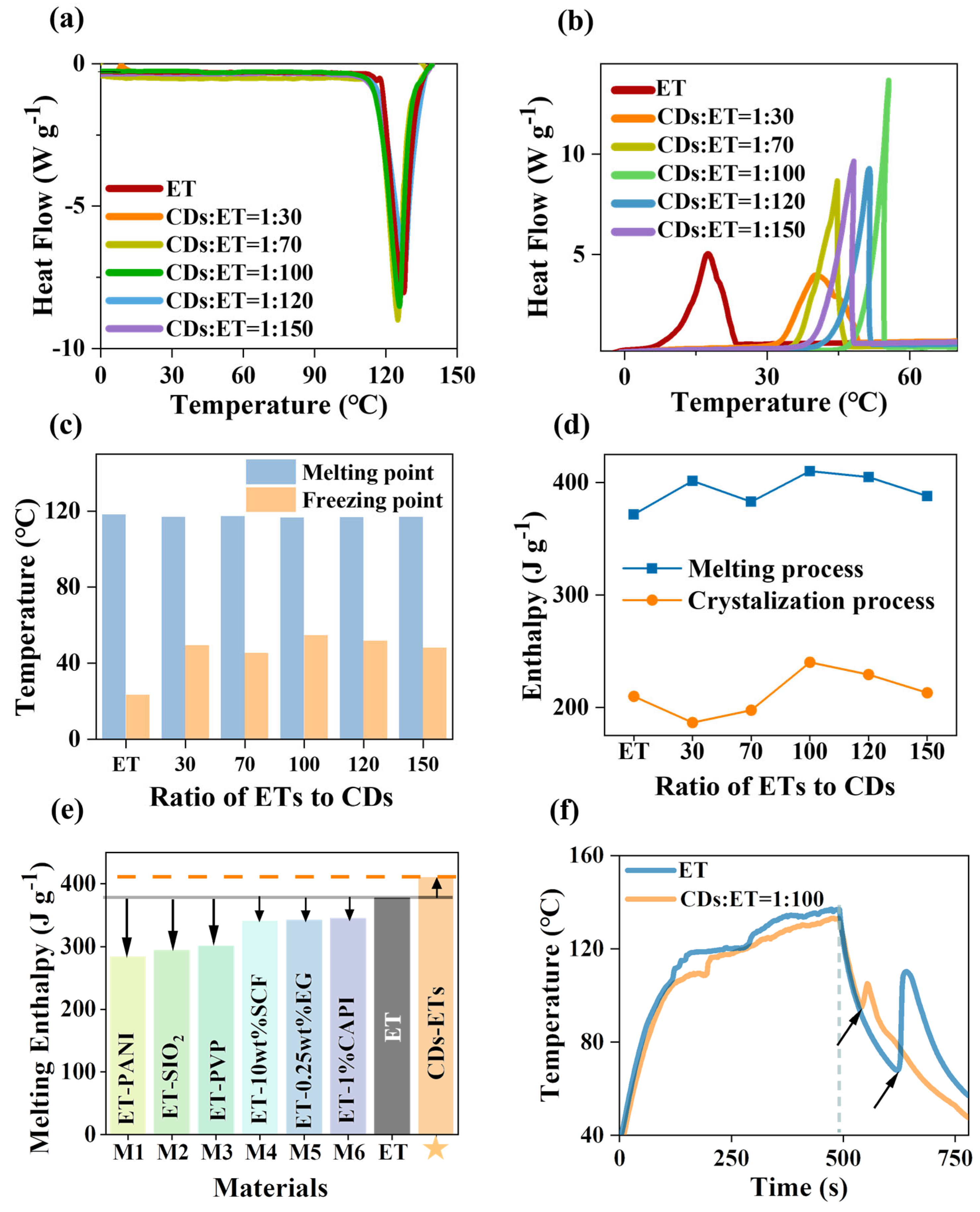
| Name | Materials | ΔHm (J g−1) | Reference |
|---|---|---|---|
| M1 | ET-PANI | 284.2 | [31] |
| M2 | ET-SIO2 | 294.3 | [32] |
| M3 | ET-PVP | 301 | [16] |
| M4 | ET-10 wt% SCF | 340.4 | [35] |
| M5 | ET-0.25 wt% EG | 342 | [34] |
| M6 | ET-1% CAPI | 344.9 | [33] |
| This work | ET-CDs | 410.2 | / |
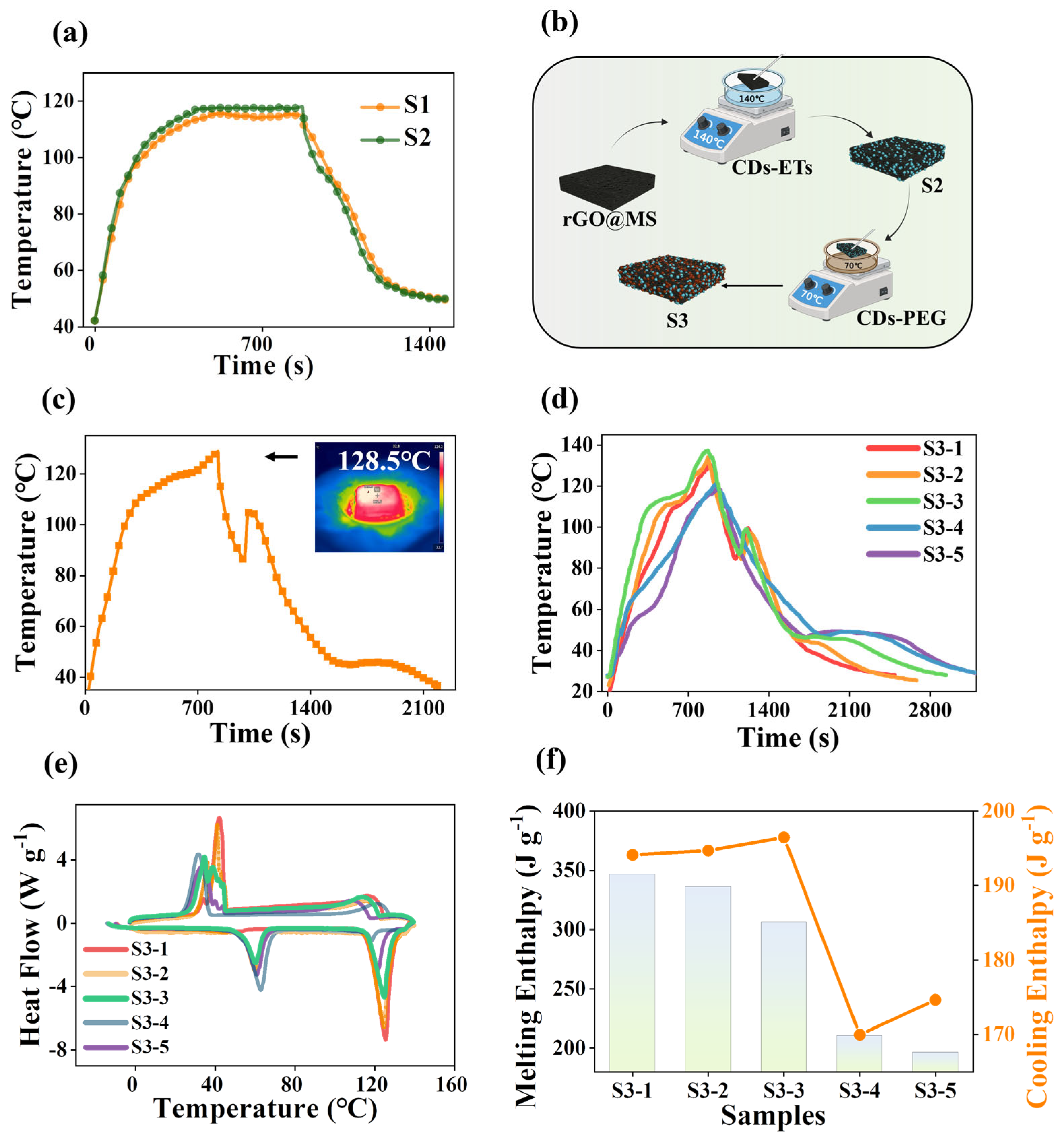
| Name | Phase-Change Materials | ΔHm (J g−1) | Reference |
|---|---|---|---|
| FSPSM-1 | Paraffin/Methyl stearate | 129.69 | [39] |
| 1%GQ-BN-PCES | Polyethylene glycol | 133.7 | [40] |
| EG-SA99 | Stearic acid | 165.44 | [41] |
| 4% EG-PEG | Polyethylene glycol | 174.38 | [42] |
| PWCQD-1 | Paraffin | 240 | [43] |
| ET-GF | Erythritol | 245.3 | [44] |
| ET@CFS | Erythritol | 282.3 | [45] |
| PANI@ET | Erythritol | 284.12 | [31] |
| S3 | Erythritol | 306.5 | This work |
Disclaimer/Publisher’s Note: The statements, opinions and data contained in all publications are solely those of the individual author(s) and contributor(s) and not of MDPI and/or the editor(s). MDPI and/or the editor(s) disclaim responsibility for any injury to people or property resulting from any ideas, methods, instructions or products referred to in the content. |
© 2025 by the authors. Licensee MDPI, Basel, Switzerland. This article is an open access article distributed under the terms and conditions of the Creative Commons Attribution (CC BY) license (https://creativecommons.org/licenses/by/4.0/).
Share and Cite
Liang, J.; Li, N.; Wu, J.; Chang, Q.; Yang, J.; Hu, S. Carbon Dot-Modulated Phase-Change Composites for Wide Temperature Range and High-Density Heat Storage and Release. Energies 2025, 18, 2597. https://doi.org/10.3390/en18102597
Liang J, Li N, Wu J, Chang Q, Yang J, Hu S. Carbon Dot-Modulated Phase-Change Composites for Wide Temperature Range and High-Density Heat Storage and Release. Energies. 2025; 18(10):2597. https://doi.org/10.3390/en18102597
Chicago/Turabian StyleLiang, Jingya, Ning Li, Jie Wu, Qing Chang, Jinlong Yang, and Shengliang Hu. 2025. "Carbon Dot-Modulated Phase-Change Composites for Wide Temperature Range and High-Density Heat Storage and Release" Energies 18, no. 10: 2597. https://doi.org/10.3390/en18102597
APA StyleLiang, J., Li, N., Wu, J., Chang, Q., Yang, J., & Hu, S. (2025). Carbon Dot-Modulated Phase-Change Composites for Wide Temperature Range and High-Density Heat Storage and Release. Energies, 18(10), 2597. https://doi.org/10.3390/en18102597