Article

Evaluating Performance of Metal-Organic Complexes as Electrodes in Hydrogen Peroxide Fuel Cells

by
Faraz Alderson
,
Raveen Appuhamy
and
Stephen Andrew Gadsden
*
Department of Mechanical Engineering, McMaster University, 1280 Main Street West, Hamilton, ON L8S 4L8, Canada
*
Author to whom correspondence should be addressed.
Energies 2025, 18(10), 2598; https://doi.org/10.3390/en18102598
Submission received: 9 April 2025 / Revised: 14 May 2025 / Accepted: 15 May 2025 / Published: 17 May 2025
(This article belongs to the Section D: Energy Storage and Application)

Abstract

:
With increasing energy demands, fuel cells are a popular avenue for portability and low waste emissions. Hydrogen fuel cells are popular due to their potential output power and clean waste. However, due to storage and transport concerns, hydrogen peroxide fuel cells are a promising alternative. Although they have a lower output potential compared to hydrogen fuel cells, peroxide can act as both the oxidizing and reducing agent, simplifying the structure of the cell. In addition to reducing the complexity, hydrogen peroxide is stable in liquid form and can be stored in less demanding methods. This paper investigates chelated metals as electrode material for hydrogen peroxide fuel cells. Chelated metal complexes are ring-like structures that form from binding organic or inorganic compounds with metal ions. They are used in medical imaging, water treatment, and as catalysts for reactions. Copper(II) phthalocyanine, phthalocyanine green, poly(copper phthalocyanine), bis(ethylenediamine)copper(II) hydroxide, iron(III) ferrocyanine, graphene oxide decorated with Fe3O4, zinc phthalocyanine, magnesium phthalocyanine, manganese(II) phthalocyanine, cobalt(II) phthalocyanine are investigated as electrode materials for peroxide fuel cells. In this study, the performance of these materials is evaluated using cyclic voltammetry. The voltammograms are compared, as well as observations are made during the materials’ use to measure their effectiveness as electrode material. There has been limited research comparing the use of these chelated metals in the context of hydrogen peroxide fuel cells. Through this research, the goal is to further the viability of hydrogen peroxide fuel cells. Poly(copper phthalocyanine) and graphene oxide doped with iron oxides had strong redox catalytic activity for use in acidic peroxide single-compartment fuel cells, where the poly(copper phthalocyanine) electrode compound generated the highest peak power density of 7.92 mW/cm2 and cell output potential of 0.634 V.

1. Introduction

Fuel cells are a method of generating electricity through chemical reactions. With rising energy demands, the technology is a promising alternative to non-renewable sources like fossil fuels [1]. Hydrogen peroxide fuel cells (HPFC) are a promising alternative to traditional hydrogen fuel cells. Hydrogen is a popular option for its power density, but it has the drawbacks of requiring high pressure and being difficult to store and transport. Although hydrogen peroxide (H2O2) has a lower theoretical maximum potential, it is stable in liquid form and water-soluble, making it much easier to store and transport. Peroxide can also act as an oxidizing and reducing agent, which reduces the complexity of the fuel cell structure as it can be reduced to a single compartment without an exchange membrane [2]. In the HPFC, the acidic H2O2 electrolyte undergoes the reaction seen in Equations (1) and (2). Here, the H2O2 reacts with the cathode, creating oxygen, a proton, and an electron. The electron moves through a circuit to generate electricity. Then, the H2O2, proton, and electron react at the anode to create water [3].
H 2 O 2 O 2 + 2 H + + 2 e
H 2 O 2 + 2 H + + 2 e 2 H 2 O
Table 1 summarizes investigations completed on various electrode materials of HPFCs. The literature usually focuses on one or two electrode material combinations, varying from organic compounds to earth metals. However, there is a gap in the literature comparing a variety of metal chelates in this application.
A chelated metal complex consists of metal ions joined in a ring-like structure [4]. They are commonly used in medical applications for detoxifying metal [5]. Complexes like deferasirox (Exjade) and deferiprone (Ferriprox) can be used as treatments for iron poisoning [6]. Beyond biomedical uses, chelated complexes are an interesting electrode material choice for fuel cells due to their catalytic ability. Darby investigated several organometallic chelate compounds in a sulfuric acid electrolyte and found the most active catalysts to be cobalt tetraazaannulene (CoTAA), iron phthalocyanine (FePc), and cobalt tetraphenylporphyrin (CoTPP) [7]. Chelated ions have been investigated for use in microbial fuel cells (MFCs) for the oxygen reduction reaction. Nguyen investigated the use of iron-chelated electrocatalysts and found them to be a promising candidate for non-platinum MFCs [8]. Carbon nanodots chelated with metal ions also enhanced current production in MFCs [9]. MFCs rely on bacterial oxidation, where bacterial cultures catalyze the electrode material to produce electricity. This contrasts with HPFC, which uses H2O2 as the catalyst for the reaction. With the success of chelated complexes in MFCs for their catalytic ability, there is a gap in research on their effectiveness in HPFCs. Chelated metals were chosen to be investigated for their resistance to acids and bases as well as their catalytic ability [10]. The metal ions in the ligand part of the chelated complex can tame the catalytic metal ion, as it regulates the ability to access, react, and catalyze [11]. This allows for metals to be used that previously could not have been. For example, a pure copper metal would oxidize in the acidic peroxide electrolyte, rendering it useless. The chelated copper ions limit how and when they undergo the reaction, allowing a limited catalytic reaction to be possible [12].
This paper examines several chelated metal complexes as redox catalytic electrodes in a single-compartment HPFC. The chelated metals chosen can be categorized as phthalocyanine and non-phthalocyanine complexes. The phthalocyanines investigated include copper(II) phthalocyanine, phthalocyanine green, poly(copper phthalocyanine), zinc phthalocyanine, magnesium phthalocyanine, manganese(II) phthalocyanine, and cobalt(II) phthalocyanine. The non-phthalocyanines chosen were bis(ethylenediamine)copper(II) hydroxide, iron(III) ferrocyanine, and graphene oxide decorated with Fe3O4. The chelated metals were selected as they belong to typical transition metals that have the potential to behave catalytically in redox settings. They have also not been examined for electrode use and were commercially available. The electrode preparation, testing methodology, and empirical testing results are provided to compare the effectiveness of metals in a fuel cell application. The objective is to validate the performance of these chelated metals and evaluate their viability in HPFCs using methods such as cyclic voltammetry.
Table 1. Table of published single-compartment HPFC investigations, PPD is peak power density, OCP is open-circuit potential.
Publication YearElectrodesAcidic Electrolyte pHOCP (V)PPD (μW/cm2)Reference
2012Ni vs. Prussian blue10.61550[13]
2012Ag vs. Prussian blue10.52700[13]
2013Ni vs. FeII[CoIII(CN)6]10.81000[14]
2020CoPC vs. Ni mesh0.1 M HCl (1.0)0.47390[15]
2020CuHCFeIII vs. Ni grid0.1 M HCl (1.0)0.728300[16]
2024ATO/FTO vs. Ni foam1.00.82320[17]
2024Ag/BiVO4 vs. FeIIIPc1.00.612030[18]
2025Carbon Fiber cloth vs. Graphite rod with surfactants1.00.6150.6[19]

2. Materials and Methods

Table 2 outlines the materials and chemicals used for this experiment. The voltammograms were made using the EmStat4S potentiostat (PALM-ES4S-LR.F0) manufactured by PalmSense BV (Houten, The Netherlands) and connected via USB to a laptop with Microsoft Windows 11 Pro. PSTrace (version 5.9) was used to control the potentiostat provided by PalmSense BV. The resolution and accuracy of the EMStat4S can be found in Table 3. The low-range model can record in the range of mV and pA. Therefore, the resolution is sufficient that noise is not a concern in these experiments. The ambient room temperature was 20 °C to 25 °C measured using a Fluke 87V-NIST True RMS Industrial Multimeter (Fluke, Everett, WA, USA) with its factory-provided K-type thermocouple probe. The room temperature was actively controlled to maintain this temperature. The same multimeter was used to measure the cell output potential values. Additionally, tools used in electrochemistry labs, such as beakers, micropipettes, calibrated scales, pH meters, heating incubators, ultrasonic water baths, and magnetic mixers, were used.

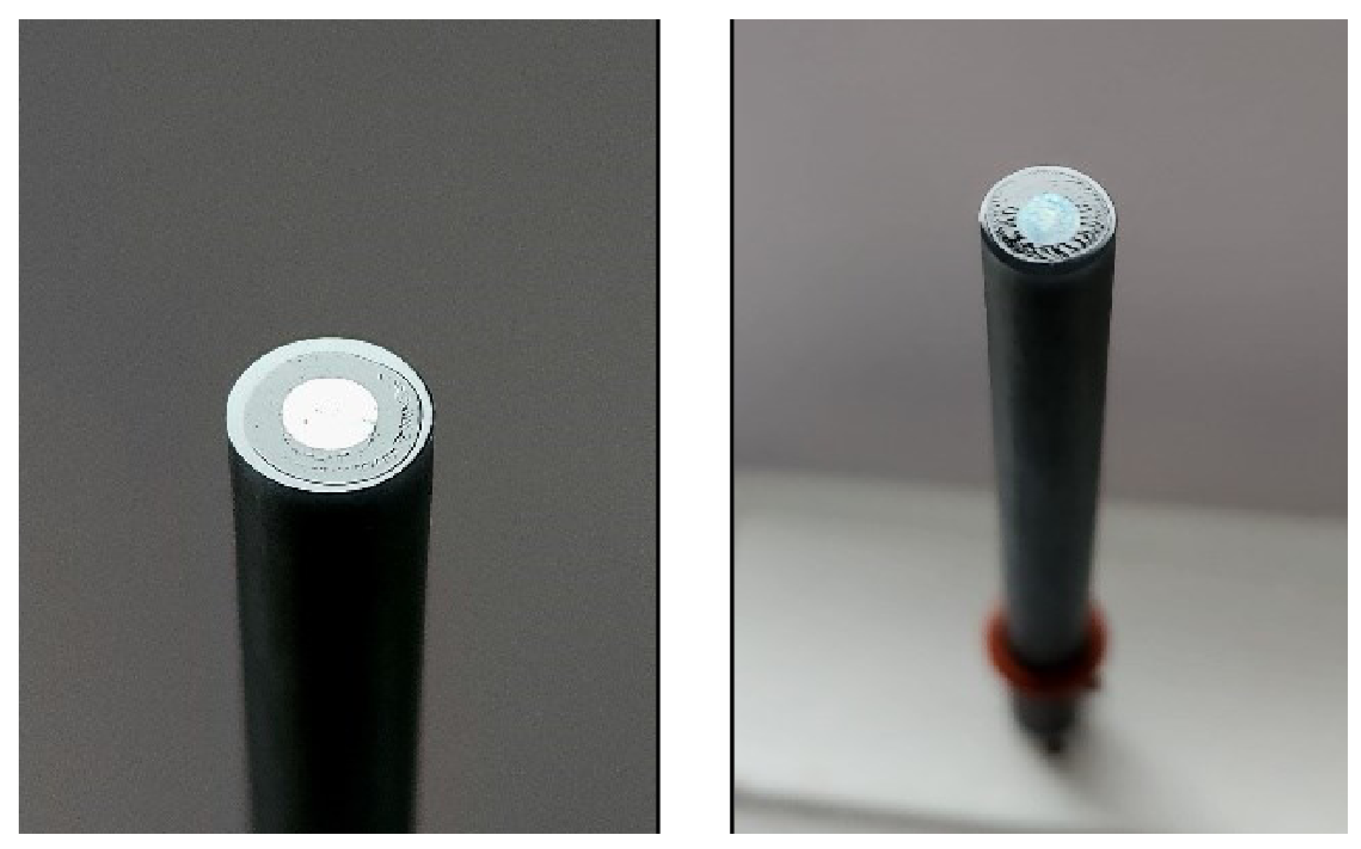
2.1. Electrode Preparation

The general procedure for preparing electrodes using chelated metal ion complexes was taken from publications using similar materials in this field. This involves creating a suspension of each chelated metal complex and decorating the surface of a glassy carbon (GC) electrode. It is common in the literature to use alcohol solvents like isopropanol to suspend chelated metal complexes for better coverage of the solute. However, organic complexing agents such as phthalocyanines and metalocyanines have low solubility in low molecular weight alcohols. THF was selected as the solvent as it has the highest average molar dissolving power [20]. Graphene oxide has also been reported to be more soluble in DMF and THF, forming more stable dispersion solutions that do not separate when stored over time [21]. Solvents like THF and DMF are popular choices for organic solvents, for their dissolving power and inert characteristics [22,23]. They have also been used to prepare electrodes in previous literature [24]. Moreover, the complexes used in this experiment are known to be more catalytically reactive rather than chemically reactive, where they accelerate other reactions rather than being used up themselves, so there should be no influence from the solvents.
The aliquots were prepared following the procedures by Yamada et al. [25]. The individual aliquots were prepared as per Table 4. They were prepared in glass vials and sonicated for 15 min to accelerate the dissolving action. Aliquot D used 70% isopropanol, as there was an oil and water-like separation in THF. After 24 h, aliquots A, B, E, F, G, H, and J had some undissolved powders at the bottom, while C and I had polymer-like substances floating at the bottom. Aliquot D formed a fully soluble solution. Literature notes that NafionTM can form complexes with the metal ions [26]. Figure 1 shows the solutions after 200 s of sonication. THF can also polymerize in the presence of strong acids, which can be found in the NafionTM polymer [27]. These observations in the solutions could be attributed to the potential interaction between the NafionTM polymer with the chelated metal complex molecules and/or THF solvent.
Aliquots A through J (except E) were remade using THF and trace amounts of TFA to improve solubility, except for E, which used a THF-isopropanol mix to maintain iron (III) ferrocyanine solubility. These were labelled A-1 through J-1, resolving previous discoloration and viscosity issues. The TFA was excluded from the remade aliquot E as the solubility of iron (III) ferrocyanine decreases in acidic solutions [28]. Iron (III) ferrocyanine formed a fully soluble solution using a volume ratio of 80% of THF and 20% of 70% isopropanol. These changes resolved the discoloration and substance formation. These newly prepared aliquots were labelled A1 through J-1, respectively.
When the aliquots were applied to the tip of a clean GC electrode, they rapidly dried due to the high vapor pressure of THF (132 mmHg at 20 °C). This left an uneven layer once the solutions had completely dried over the surface of the GC electrode. Aliquots A-1 through J-1, except for E-1, were remade using a base solvent comprised of 785 parts DMF, 200 parts THF, and 15 parts TFA. The new E-1 solvent used a mixture of 700 parts DMF, 100 parts THF, and 200 parts 70% isopropanol. Despite its lower solubility, a base solution made predominantly of DMF ensured a lower and more even evaporation rate due to its lower vapor pressure of 3.9 mmHg. The new aliquots were labelled as A-2 through J-2. When applied onto the GC electrode, they no longer evaporated rapidly and formed an even layer of respective chelated metal complex materials.
The procedure to prepare the electrode for each solution of aliquots A-2 through J-2 was adopted in part from Yamada et al., where a Fe complex was dissolved in benzonitrile with a trace amount of TFA and applied to a GC carbon electrode. The electrode was dried in a 70 °C oven for 40 min and then coated in a Nafion solution and then dried in an oven again [25]. For this experiment, before the complexes were applied to the GC electrodes, the GC electrodes were polished. Before every use, the electrode was polished using 5000, 14,000, and 50,000 grit polishing pastes on a thin microfiber cloth using a figure-8 motion to ensure even polishing. After the polishing, the electrodes were rinsed using 70% isopropanol and sonicated in 70% isopropanol for 200 s. After being sonicated, the electrodes were rinsed with reverse-osmosis water and left to dry at room temperature. A total of 7 µL of each chelated metal complex aliquot was pipetted onto the surface of the clean GC electrode in three stages. A total of 7 µL was experimentally optimized through testing for optimal and even electrode coverage. First, 3 µL was dispensed and then left to dry in a 75 °C oven. Then, 2 µL was dispensed and dried at the same temperature and time. The remaining aliquot was then added and dried in the same way. Once the entire 7 µL was applied and dried, the electrode tip was covered with 10 µL of 5% Nafion™ polymer solution in methanol and was allowed to dry fully by placing it in the 75°C oven for 15 min. The purpose of the final heating process is to ensure the electrode is fully set and does not impact the Nafion structure. The fully decorated electrodes were cooled off to room temperature before use in the experiments. Figure 2 shows what the decorated electrode looks like after the procedure is completed.
E-2 was used as the reference for this experiment, as it has already been investigated in the literature. The resulting voltammogram for E-2 looked distinctly different from what has been reported in previous investigations [13]. After preparing the electrode with aliquot E solution (the Nafion™mixed in with the chelated metal complex), the voltammogram improved, as the results looked similar to the results of the reference study. As these compounds, more specifically the phthalocyanines, are known to be great conductors of electricity [29], trace amounts of lampblack carbon were added to enhance the electrode’s electrical conductivity. The new aliquots were prepared according to Table 5 and labelled A-3 to J-3. The lampblack carbon was made by collecting carbon black from holding clean glass over a flame of a pure paraffin candle, then scraping it off using a sterile scalpel into a glass vial. Though this is an unconventional method to collect the carbon, the use of sterile equipment would not affect the catalytic reaction, only the conductivity. Aliquot E-3 was kept the same as E-2, with the same application method as the reference publication, as it was kept as the reference. After preparing A-3 through J-3, each vial was sonicated for 200 s before 200 s, before they were used to decorate the glassy electrode in the same steps as before, without the final application of Nafion™. All the voltammetry and open-circuit potential tests were conducted using aliquots A-3 through J-3.

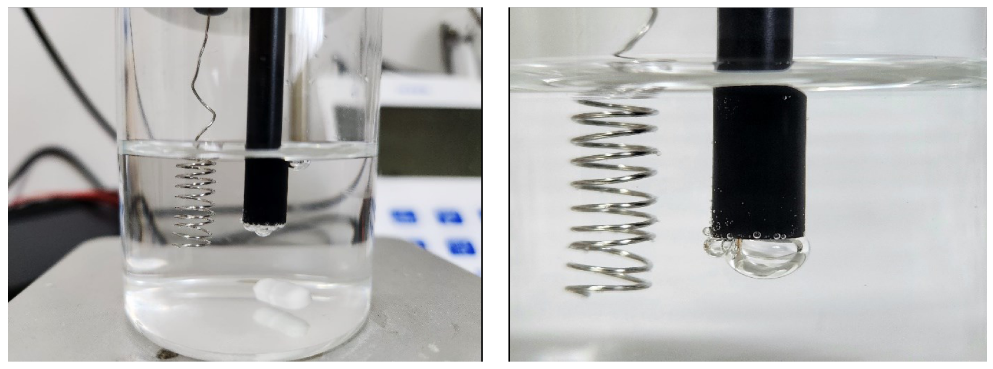
2.2. Fuel Cell Setup and Preparation of Electrolytes

The performance of the electrodes was evaluated using a single-compartment fuel cell (Figure 3). This fuel cell setup consisted of the cell chamber (a 100 mL glass beaker), filled with 50 mL of an acidic hydrogen peroxide electrolyte (containing 0.5 M hydrogen peroxide, 1 M sodium chloride, and 0.1 M hydrochloric acid in reverse-osmosis water). The electrolyte and pH were kept consistent for all experiments. A Teflon cap with pre-drilled holes for electrode placement was used to cover the beaker and placed over a magnetic mixer. The cell output potential was measured by pairing the electrode combinations after 3 min of the electrodes being submerged. The voltammograms were generated using the potentiostat, with each chelated metal complex electrode as the working electrode, the coiled wire platinum electrode as the counter electrode, and the Ag/AgCl filled with 3M NaCl as the reference electrode.

2.3. Methodology

First, the cell output potentials of the electrodes are tested to evaluate the electrode materials. They were paired with silver (Ag), platinum (Pt), antimony (Sb) and tantalum (Ta). These metals have been previously evaluated to be effective electrode materials in HPFCs [30]. The cell output values will also help determine the catalytic behavior of chelated metal ions. A positive cell output potential demonstrates cathodic behavior, while a negative cell output potential demonstrates anodic catalytic behavior. Then, using the Emstat4s, the cyclic voltammograms of the electrodes were determined. By analyzing the voltammograms, a more detailed understanding of the catalytic behavior can be determined.

3. Results

3.1. Experimental Observations

GC is a typical inert electrode material used in electrochemical studies with extreme pH values. However, it was observed that the bare surface formed a slight corrosion layer after three cycles of cyclic voltammetry in the acidic electrolyte using a scanning potential range of −0.2 V to 0.5 V. Other studies have not reported such observations, perhaps due to them using decorated GC electrodes rather than bare ones [25]. Before reuse, the corrosion was removed from the electrode surface using routine polishing procedures. During the cyclic voltammetry runs (potential scan range of −0.5 V to 0.5 V), a top layer of corrosion was again seen on the glassy electrode decorated with A-2 and F-2.
The voltammetry runs with G-3, H-3, and J-3 caused gas bubble formation on the electrode tip, indicating a potential case of hydrogen peroxide disproportionation (as seen in Figure 4). This is a secondary degradation reaction where the peroxide is only reacting with itself and is not catalytically productive. However, further investigations are required to identify the specific reason for the bubbles. Some experiments used Nafion™to limit the exposure of the electrolyte to the catalytic metal to prevent the disproportionation [25]. Therefore, the H-3 and G-3 electrodes were coated with 10 µL of Nafion™solution eliminated the gas generation while still producing a strong voltammogram. A smaller gas bubble generation was also observed on the I-3 decorated electrode. However, Nafion™was not used for this electrode to prevent the gas bubble generation. Stirring caused no major changes in cell output potential in the aliquots except for G-2 and Ta, where the potential was measured as far as −502 mV from zero.
All measurements were conducted in triplicate, and the mean value was subsequently calculated for each set. For all measurements, individual replicate values fell within ± 10 % of the corresponding mean, indicating low intra-assay variability. The relative standard deviation for each triplicate set was consistently below the 10 % threshold, reflecting a high degree of precision. This suggests that the method exhibited strong repeatability across all experimental conditions.

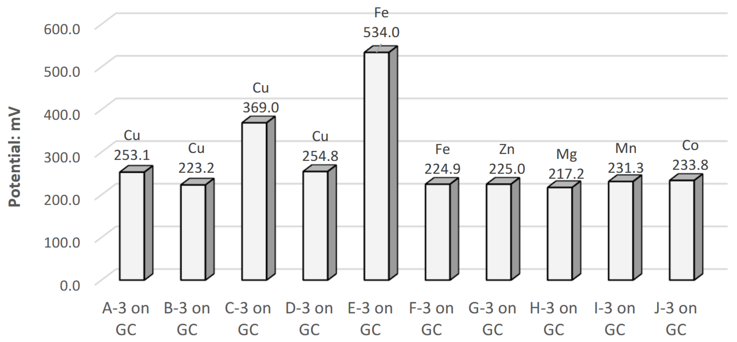
3.2. Fuel Cell Performance—Cell Output Potential

The A-2 through J-2 decorated electrodes were paired with acid-compatible electrodes made of silver, platinum, antimony, and tantalum, and the cell output potential under load was measured as shown in Table 6. The cells of the table are formatted to mark the higher and lower potential values. The darker the color, the higher the cell output potential.

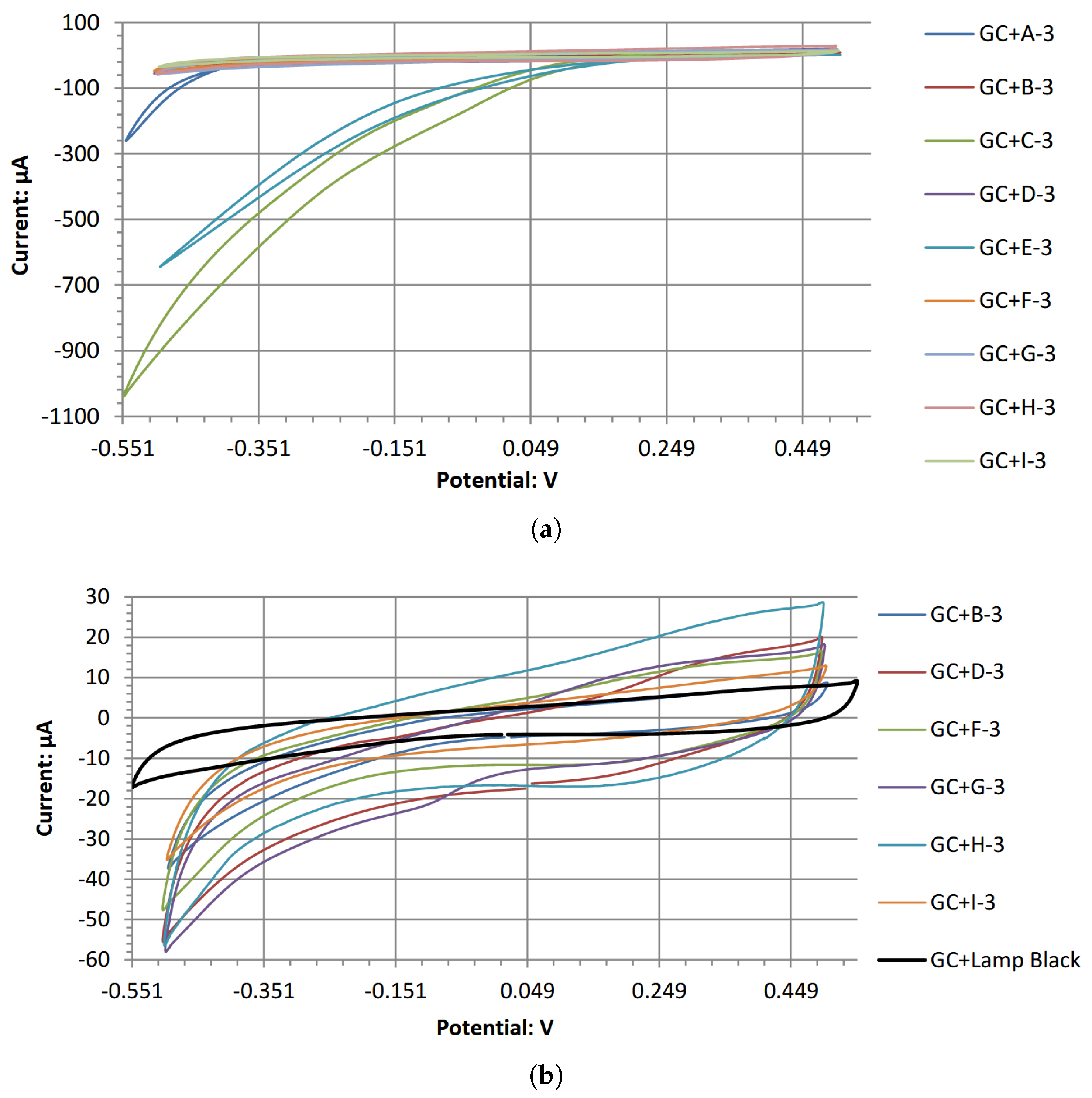
3.3. Fuel Cell Performance—Open-Circuit Potential and Cyclic Voltammetry

The open-circuit potentials with the Ag/AgCl reference electrode for A-3 through J-3 decorated electrodes are summarized in Figure 5. An adjustment of +209 mV was made to account for the reference electrode’s reduction potential, which is a standard value. The cyclic voltammograms for all high-performing electrodes in the acidic electrolyte are overlapped in Figure 6. The individual cyclic voltammograms of each electrode material can be found in Figure A1, Figure A2, Figure A3, Figure A4, Figure A5, Figure A6, Figure A7, Figure A8, Figure A9 and Figure A10 in Appendix A. The cyclic voltammograms for each material are asymmetrical. This is expected as the reaction is irreversible; a symmetrical voltammogram would be a rare occurrence due to the differences in the cathodic and anodic chemical reaction [31]. Further investigations would be required to determine the specific source of the asymmetry. Each chelated metal complex electrode’s relative peak power density was extrapolated using its respective voltammogram’s highest current densities and potential values, normalized using the GC surface, as it has an even layer of the chelated metal. The calculated values are in Table 7.

4. Discussion

To the best of current knowledge, few studies have compared various chelated metal complex materials for their catalytic potential in acidic HPFCs, as demonstrated in this experiment. Poly(copper phthalocyanine) and graphene oxide doped with iron oxides were identified as the highest-performing chelated metal complexes with strong redox catalytic activity. Poly(copper phthalocyanine)’s high open-circuit potential shows that its electrochemical catalytic performance has surpassed its monomeric version. It has also demonstrated the ability to create similar and, in some cases, better cell output potential than Prussian blue, an extensively researched, high-performing chelated metal complex. Zinc and magnesium phthalocyanine produced significant cell output potentials when paired with a silver electrode, but a lower current output based on cyclic voltammogram data. All chelated metal complex electrode compounds work well when paired with Ag, Sb, and Ta electrodes, while Pt electrodes generate the lowest output potential. Despite strong literature support, A-2 (copper phthalocyanine) did not generate substantial amounts of cell output potential, highlighting that electrochemical measurements of an electrolyte or electrode may not directly correlate with the performance of the fuel cell setup. Table 6 shows the output potentials of the different electrode combinations. Most of the chelated metal complex materials are favored as cathodic catalysts in acidic hydrogen peroxide conditions. H-3 and I-3 had very low catalytic tendencies against the acidic peroxide. Therefore, it is likely that the electrodes have low current values, leading to fuel cells with low current densities and power output.
Prussian blue with antimony produced the highest increase in cell output potential, while B-2 delivered the lowest. B-2 is similar to A-2, except that A-2 has been halogenated with chlorine at all three outer ends of each of its four isoindole/di-iminoisoindole moieties. The halogenation of electrically conductive organic materials can sometimes disrupt their electron flow and reduce the mobility of electrons across the molecule. Chlorine is an electronegative atom and hinders the flow of electrons across the phthalocyanine’s molecular structure. This electron disruption likely causes a reduction in the catalytic reaction dynamics, decreasing its ability to produce a high output potential.
F-2 is composed of magnetizable graphene oxide nanoparticles doped with iron oxides, containing iron at both Fe2+ and Fe3+ oxidation states. It performed worse than Prussian blue (E-2), the other iron-containing metal complex, in cell output potential and open-circuit potential. F-2 generated an output potential that is marginally lower than C-2. Although F-2 and F-3 performed better than in previous literature, they were still not comparable to Prussian blue, which is probably due to the differences in molecular structure. Graphene oxide has less densely packed iron oxide molecules compared to Prussian blue, where every molecule contains roughly two iron ions. The iron atoms in Prussian blue are in an ionized chelated form, whereas they are in iron oxide form in the doped graphene oxide. Iron oxide may be less catalytically reactive than the chelated ion form. The presence of hydroxyl groups on the reduced graphene oxide may act as electronegative sites, slowing down the rate at which electrons travel across graphene nanosheets.
Among the copper ion complexes of A-2, C-2, and D-2, D-2 performed better at generating a cell output potential than A-2 and B-2; however, it performed worse than C-2 in both output and open-circuit potentials. D-2 used bis(ethylenediamine)copper(II) hydroxide, where a copper atom is complexed with two ethylenediamine molecules and attached to two hydroxides. Exposing it to an acidic pH removes the two hydroxide moieties of copper, leaving a copper core with a 2+ charge (Cu2+ oxidation state). Since the D-2 molecules are smaller than the phthalocyanines of copper, this leads to faster catalytic reaction kinetics. Alternatively, hydrogen peroxide may react differently with each of the copper ion-based compounds, where the peroxide molecule favors a faster catalytic reaction with bis(ethylenediamine)copper(II) than monomeric copper phthalocyanines. C-2 is probably capable of more catalytic activity in acidic peroxide fuel cells than its monomeric form for similar reasons. Figure 7 shows the cyclic voltammograms for the two chelated copper complexes. The polymeric version shows an earlier onset potential with a substantially higher catalytic current generation during the cathodic voltage sweep.
The reported open-circuit potential (OCP) for A-2 in this study of 0.253 V was lower than the 0.57 V reported in previous literature [15]. As the concentration of hydrogen peroxide and electrolytic salt in the electrolyte would only impact the cell’s current and not the potential of the cell’s performance, the potential difference can be attributed to the solution’s pH and the electrode construction. Both this experiment and the cited literature used an acidic peroxide electrolyte containing 0.1 M of hydrochloric acid; however, the method used by Nguyen et al. to fabricate the copper phthalocyanine electrode mixed “conductive enhancing” additives with the copper complex. These additives include carbon black, multi-walled carbon nanotubes, and polyvinylidene difluoride as a binder before being applied onto the surface of a conductive carbon paper. This paper did not use as many additives and was applied to a GC electrode surface, one of the most neutral and non-reactive conductive carbon-based substrates. Carbon nanoparticles have also been investigated in many fuel cell applications as catalytic electrode materials [32]. Therefore, the reported open-circuit potential of 0.57 V by Nguyen et al. may be the result of the combined reaction of the copper phthalocyanine and the carbon nanotubes in the acidic electrolyte, whereas the 0.253 V with the simpler electrode fabrication methods of this paper represents the monomeric copper phthalocyanine’s electrocatalytic attributes. Figure A1 shows the cyclic voltammograms for A-2 with and without hydrogen peroxide. The voltammogram shows a uniform shape that represents a clean and single-ordered catalytic behavior. Figure 6b shows that the same electrode without copper phthalocyanine is free of any catalytic activity. This differs from Nguyen et al., where the same voltammograms have a non-uniform shape, and the peroxide-free voltammogram is not linearly aligned near zero amps. This further showcases copper phthalocyanine’s electrochemical attributes.
Electrodes E-2 and E-3 perform closely to what is reported in the literature using Prussian blue [13]. They had a measured OCP of 0.6 V, which is similar to the reported 0.534 V with similar voltammogram shapes. However, the current output from this electrode is much higher in this experiment than in the previously mentioned literature. This current difference is likely attributed to the 1 M of NaCl used along with the same peroxide content and acidity. The salt would greatly improve the ionic conductivity of the electrolyte, resulting in a higher current output.
Peak power densities are used for comparative purposes to evaluate the performance of a cell. Comparisons can be made if all testing conditions are similar. These conditions include electrolyte pH, fuel (hydrogen peroxide) concentration, electrolytic salt type and concentration, voltammetry sweep range, and sweep rate. Table 7, all peak power densities are reported from similar testing conditions and hence can be cross-compared. The peak power density was determined using the highest potential point and corresponding current value from the respective voltammograms. Though they had similar potentials near 0.5 V, the novel electrode C-3 generated the highest peak power density of 7.92 mW/cm2 at 0.54 V. When comparing the power density with previous literature in Table 1, this is one of the highest reported in the literature for a selective cathode catalyst in acidic hydrogen peroxide fuel cells. The second and third highest power densities were generated by E-3 (Prussian blue) and J-3 (cobalt phthalocyanine). The remainder of the tested compounds produce significantly lower peak power densities near the same potential, in the micro-amperes range per square centimeter of electrode surface.

5. Conclusions

This is one of the first experiments to investigate seven different chelated metal complex materials for their catalytic potential in hydrogen peroxide fuel cells. This paper outlined the procedure of preparing the chelated metals into aliquots and then preparing them on GC electrodes. The output potentials of the electrode combinations and the cyclic voltammograms were collected. The results justified that polymeric poly(copper phthalocyanine) was the highest-performing electrode. It had the highest reported cell output potential of 0.634 V, which performed better than this monomer form. It also generated the highest peak power density of 7.92 mW/cm2, one of the highest reported in the literature for a cathode catalyst in acidic hydrogen peroxide fuel cells, potentially due to the interaction of the acidic electrolyte with the hydroxide moieties of copper. These results can be further used by testing the electrode material in a single and dual-compartment configuration. The electrode materials can also be scaled to generate meaningful amounts of electricity. This experiment focused on the observed performance of these electrode materials. In the future, utilizing technologies like SEM to observe the molecular structure of the electrode materials during these reactions will strengthen the research.

6. Patents

The work reported in this manuscript is used in the USPTO provisional patent application number: 63/637522.

Author Contributions

Conceptualization, F.A.; methodology, F.A.; software, F.A.; validation, F.A.; formal analysis, F.A.; investigation, F.A.; resources, F.A.; data curation, F.A.; writing—original draft preparation, F.A.; writing—review and editing, R.A.; visualization, F.A.; supervision, S.A.G.; project administration, S.A.G.; funding acquisition, S.A.G. All authors have read and agreed to the published version of the manuscript.

Funding

This research received no external funding.

Data Availability Statement

The raw data supporting the conclusions of this article will be made available by the authors on request.

Conflicts of Interest

The authors declare no conflicts of interest. The funders had no role in the design of the study; in the collection, analyses, or interpretation of data; in the writing of the manuscript; or in the decision to publish the results.

Abbreviations

The following abbreviations are used in this manuscript:
MFCMicrobial Fuel Cell
HPFCHydrogen Peroxide Fuel Cell
GCGlassy Carbon
ACopper (II) phthalocyanine
BPhthalocyanine green
CPoly(copper phthalocyanine)
DBis(ethylenediamine)copper (II) hydroxide
EIron (III) ferrocyanine
FGraphene oxide decorated with Fe304
GZinc phthalocyanine
HMagnesium phthalocyanine
IManganese (II)phthalocyanine
JCobalt (II) phthalocyanine
NaClSodium Chloride
FeIron

Appendix A

The following are the individual cyclic voltammograms for the tested electrode materials.
Figure A1. Cyclic voltammogram of copper (II) phthalocyanine.
Energies 18 02598 g0a1
Figure A2. Cyclic voltammogram of phthalocyanine green.
Energies 18 02598 g0a2
Figure A3. Cyclic voltammogram of poly(copper phthalocyanine).
Energies 18 02598 g0a3
Figure A4. Cyclic voltammogram of bis(ethylenediamine)copper (II) hydroxide.
Energies 18 02598 g0a4
Figure A5. Cyclic voltammogram of iron (III) ferrocyanine.
Energies 18 02598 g0a5
Figure A6. Cyclic voltammogram of graphene oxide decorated with Fe3O4.
Energies 18 02598 g0a6
Figure A7. Cyclic voltammogram of zinc phthalocyanine.
Energies 18 02598 g0a7
Figure A8. Cyclic voltammogram of magnesium phthalocyanine.
Energies 18 02598 g0a8
Figure A9. Cyclic voltammogram of manganese (II) phthalocyanine.
Energies 18 02598 g0a9
Figure A10. Cyclic voltammogram of cobalt (II) phthalocyanine.
Energies 18 02598 g0a10

References

  1. Mekhilef, S.; Saidur, R.; Safari, A. Comparative Study of Different Fuel Cell Technologies. Renew. Sustain. Energy Rev. 2012, 16, 981–989. [Google Scholar] [CrossRef]
  2. Alderson, F.A. Investigation and Advancement of Novel Single Compartment Hydrogen Peroxide Fuel Cells. Ph.D. Thesis, University of Guelph, Guelph, ON, Canada, 2023. [Google Scholar]
  3. An, L.; Zhao, T.; Yan, X.; Zhou, X.; Tan, P. The Dual Role of Hydrogen Peroxide in Fuel Cells. Sci. Bull. 2015, 60, 55–64. [Google Scholar] [CrossRef]
  4. Mellor, D.P. CHAPTER 1—Historical Background and Fundamental Concepts. In Chelating Agents and Metal Chelates; Dwyer, F.P., Mellor, D.P., Eds.; Academic Press: Cambridge, MA, USA, 1964; pp. 1–50. [Google Scholar] [CrossRef]
  5. Flora, G.; Mittal, M.; Flora, S.J.S. 26—Medical Countermeasures—Chelation Therapy. In Handbook of Arsenic Toxicology; Flora, S.J.S., Ed.; Academic Press: Oxford, UK, 2015; pp. 589–626. [Google Scholar] [CrossRef]
  6. Gerhardsson, L.; Kazantzis, G. Chapter 23—Diagnosis and Treatment of Metal Poisoning: General Aspects. In Handbook on the Toxicology of Metals, 4th ed.; Nordberg, G.F., Fowler, B.A., Nordberg, M., Eds.; Academic Press: San Diego, CA, USA, 2015; pp. 487–505. [Google Scholar] [CrossRef]
  7. Darby, R.; Yamana, M.; Dhar, H.; White, R. Metal Chelate Catalysts for Fuel Cells; Final Report, June 1979–October 1982; Texas A&M University, Department of Chemical Engineering: College Station, TX, USA, 1982. [Google Scholar]
  8. Nguyen, M.T.; Mecheri, B.; D’Epifanio, A.; Sciarria, T.P.; Adani, F.; Licoccia, S. Iron Chelates as Low-Cost and Effective Electrocatalyst for Oxygen Reduction Reaction in Microbial Fuel Cells. Int. J. Hydrogen Energy 2014, 39, 6462–6469. [Google Scholar] [CrossRef]
  9. Loukanov, A.; Angelov, A.; Takahashi, Y.; Nikolov, I.; Nakabayashi, S. Carbon Nanodots Chelated with Metal Ions as Efficient Electrocatalysts for Enhancing Performance of Microbial Fuel Cell Based on Sulfate Reducing Bacteria. Colloids Surf. Physicochem. Eng. Asp. 2019, 574, 52–61. [Google Scholar] [CrossRef]
  10. Abdulrahman Hamad, O.; Kareem, R.O.; Khdir Omer, P. Recent Developments in Synthesize, Properties, Characterization, and Application of Phthalocyanine and Metal Phthalocyanine. J. Chem. Rev. 2024, 6, 39–75. [Google Scholar] [CrossRef]
  11. Martell, A.E. Catalytic Effects of Metal Chelate Compounds. Pure Appl. Chem. 1968, 17, 129–178. [Google Scholar] [CrossRef]
  12. Kojima, T. Overview of the Catalytic Chemistry of Metal Complexes. In Redox-Based Catalytic Chemistry of Transition Metal Complexes; Kojima, T., Ed.; Royal Society of Chemistry: London, UK, 2024; Volume 2. [Google Scholar] [CrossRef]
  13. Shaegh, S.A.M.; Nguyen, N.T.; Ehteshami, S.M.M.; Chan, S.H. A Membraneless Hydrogen Peroxide Fuel Cell Using Prussian Blue as Cathode Material. Energy Environ. Sci. 2012, 5, 8225–8228. [Google Scholar] [CrossRef]
  14. Yamada, Y.; Yoneda, M.; Fukuzumi, S. A Robust One-Compartment Fuel Cell with a Polynuclear Cyanide Complex as a Cathode for Utilizing H2O2 as a Sustainable Fuel at Ambient Conditions. Chem. Eur. J. 2013, 19, 11733–11741. [Google Scholar] [CrossRef]
  15. Nguyen, B.; Kuperman, N.; Goncher, G.; Solanki, R. Membraneless H2O2 Fuel Cells Driven by Metallophthalocyanine Electrocatalysts. ECS J. Solid State Sci. Technol. 2020, 9, 061009. [Google Scholar] [CrossRef]
  16. Martins, R.F.; Martins, D.A.A.; Costa, L.A.C.; Matencio, T.; Paniago, R.M.; Montoro, L.A. Copper Hexacyanoferrate as Cathode Material for Hydrogen Peroxide Fuel Cell. Int. J. Hydrogen Energy 2020, 45, 25708–25718. [Google Scholar] [CrossRef]
  17. Devassy, A.M.C.; Wankhede, K.D.; Kamalakshan, A.; Mandal, S. A Robust Single Compartment Peroxide Fuel Cell Using Mesoporous Antimony Doped Tin Oxide as the Cathode Material. Nanoscale 2024, 16, 12060–12070. [Google Scholar] [CrossRef] [PubMed]
  18. Miao, Z.; Wang, R.; Li, X.; Sun, F.; Ge, M.; Huang, N.; Zhao, Y.; Chang, Z.; Wang, H. Photoreduced Ag Nanoparticles-Decorated BiVO4 Nanoplates as Photoanode Boosting Photoelectrochemical H2O2 Fuel Cell Performance. J. Power Sources 2025, 629, 235998. [Google Scholar] [CrossRef]
  19. Zhu, F.; Kuzin, A.; Chen, G.; Gorin, D.A.; Mohan, B.; Huang, G.; Zhao, S.; Mei, Y.; Solovev, A.A. Green Energy for Autonomous Devices: Surfactant-Enhanced Membraneless Hydrogen Peroxide Fuel Cells. In Proceedings of the 2023 International Conference on Manipulation, Automation and Robotics at Small Scales (MARSS), Abu Dhabi, United Arab Emirates, 9–13 October 2023; pp. 1–6. [Google Scholar] [CrossRef]
  20. Ghani, F.; Kristen, J.; Riegler, H. Solubility Properties of Unsubstituted Metal Phthalocyanines in Different Types of Solvents. J. Chem. Eng. Data 2012, 57, 439–449. [Google Scholar] [CrossRef]
  21. Paredes, J.I.; Villar-Rodil, S.; Martínez-Alonso, A.; Tascón, J.M.D. Graphene Oxide Dispersions in Organic Solvents. Langmuir 2008, 24, 10560–10564. [Google Scholar] [CrossRef]
  22. Sargent, M.; Dean, F. Furans and Their Benzo Derivatives: (Ii) Reactivity. In Comprehensive Heterocyclic Chemistry; Elsevier: Amsterdam, The Netherlands, 1984; pp. 599–656. [Google Scholar] [CrossRef]
  23. Heravi, M.M.; Ghavidel, M.; Mohammadkhani, L. Beyond a Solvent: Triple Roles of Dimethylformamide in Organic Chemistry. RSC Adv. 2018, 8, 27832–27862. [Google Scholar] [CrossRef]
  24. Monteiro, I.F.; Pinto, R.S.; Silva, M.M.; Fidalgo-Marijuan, A.; Costa, C.M.; Lanceros-Méndez, S.; Gonçalves, R. Lithium-Ion Battery High Performance Cathode Electrode Based on LiFePO4 and Thermal Sensitive Microspheres with Thermal Shutdown Properties. J. Power Sources 2024, 614, 234956. [Google Scholar] [CrossRef]
  25. Yamada, Y.; Yoshida, S.; Honda, T.; Fukuzumi, S. Protonated Iron–Phthalocyanine Complex Used for Cathode Material of a Hydrogen Peroxide Fuel Cell Operated under Acidic Conditions. Energy Environ. Sci. 2011, 4, 2822–2825. [Google Scholar] [CrossRef]
  26. Ramkumar, J. Metal Ion Uptake Behaviour of Nafion in Presence of Organic Complexing Reagents. Moj Bioorg. Org. Chem. 2017, 1, 1–3. [Google Scholar] [CrossRef]
  27. Pruckmayr, G.; Wu, T.K. Polymerization of Tetrahydrofuran by Proton Acids. Macromolecules 1978, 11, 662–668. [Google Scholar] [CrossRef]
  28. Meeussen, J.C.L.; Keizer, M.G.; Van Riemsdijk, W.H.; De Haan, F.A.M. Dissolution Behavior of Iron Cyanide (Prussian Blue) in Contaminated Soils. Environ. Sci. Technol. 1992, 26, 1832–1838. [Google Scholar] [CrossRef]
  29. Lo, P.C.; Leng, X.; Ng, D.K.P. Hetero-Arrays of Porphyrins and Phthalocyanines. Coord. Chem. Rev. 2007, 251, 2334–2353. [Google Scholar] [CrossRef]
  30. Alderson, F.; Appuhamy, R.; Gadsden, S.A. Investigation of Select Pure Earth Metals as Redox Catalytic Electrodes in Single Compartment Hydrogen Peroxide Fuel Cells. Appl. Sci. 2025, 15, 1857. [Google Scholar] [CrossRef]
  31. Aoki, K.J.; Chen, J.; Aoki, K.J.; Chen, J. Tips of Voltammetry. In Voltammetry; IntechOpen: London, UK, 2018. [Google Scholar] [CrossRef]
  32. Luo, C.; Xie, H.; Wang, Q.; Luo, G.; Liu, C. A Review of the Application and Performance of Carbon Nanotubes in Fuel Cells. J. Nanomater. 2015, 2015, 560392. [Google Scholar] [CrossRef]
Figure 1. Aliquots A through J, one day after preparation and right after 200 s of sonication.
Energies 18 02598 g001
Figure 2. Glassy carbon surface of the electrode decorated with layers of E-2 and covered with Nafion™, shown at two different angles.
Energies 18 02598 g002
Figure 3. A three-electrode cell setup attached to a potentiostat for voltammetry tests.
Energies 18 02598 g003
Figure 4. Demonstration of gas bubble formation and cumulation on the electrode tip, as seen with the glassy carbon electrodes decorated with G-3, H-3, and J-3.
Energies 18 02598 g004
Figure 5. Open-circuit potentials of A-3 through J-3 decorated glassy carbon (GC) electrode in Acidic Electrolyte 2. All of them being positive shows that all the materials have a cathodic tendency, where E-3 is the most reactive.
Energies 18 02598 g005
Figure 6. Overlapped cyclic voltammograms of the electrodes tested. A-3, C-3, E-3 were removed in (b) to improve the visibility of the remaining results. (a) The cyclic voltammograms of A-3 through K-3 electrodes in the acidic electrolyte. (b) The cyclic voltammograms without A-3, C-3, E-3.
Energies 18 02598 g006
Figure 7. Overlapped cyclic voltammograms of A-3 and C-3 on GC in acidic peroxide electrolyte.
Energies 18 02598 g007
Table 2. Overview of compounds and materials used with their sources and purities.
Compound/MaterialSourcePurityCAS #
Ag/AgCl (3 M NaCl) reference electrodeBASi Research Products (West Lafayette, IN, USA)N/AN/A
Bis(ethylenediamine)copper(II) hydroxideMillipore Sigma (Burlington, VT, USA)1 Molar14552-35-3
Cobalt (II) phthalocyanineMillipore Sigma (Burlington, VT, USA)97%3317-67-7
Copper (II) phthalocyanineMillipore Sigma (Burlington, VT, USA)90%147-14-8
Copper hexadecachlorophthalocyanine (phthalocyanine green)Millipore Sigma (Burlington, VT, USA)Not disclosed14832-14-5
Dichloromethane (DCM)Millipore Sigma (Burlington, VT, USA)99.8%1975-09-02
Dimethylformamide (DMF)Millipore Sigma (Burlington, VT, USA)99.9%1968-12-02
Glassy carbon electrode (3.0 mm diameter)BASi Research Products (West Lafayette, IN, USA)N/AN/A
Graphene oxide decorated with iron oxide (containing both Fe2+ and Fe3+ ions)Abalonyx Innovative Materials (Oslo, Norway)Not disclosedN/A
Hydrochloric acidMillipore Sigma (Burlington, VT, USA)37%7647-01-0
Hydrogen peroxide (industrial grade)Arkema (Columbes, France)50%7722-84-1
Iron(III) ferrocyanine (Prussian blue)Millipore Sigma (Burlington, VT, USA)Not disclosed14038-43-8
IsopropanolVWR (Radnor, PA, USA)70%67-63-0
Magnesium phthalocyanineMillipore Sigma (Burlington, VT, USA)90%1661-03-6
Manganese(II) phthalocyanineMillipore Sigma (Burlington, VT, USA)100%14325-24-7
Microfiber clothFosmon (Woodbury, NY, USA)N/AN/A
Nafion™ 117Millipore Sigma (Burlington, VT, USA)5%31175-20-9
Platinum wire electrode (MW-1033)BASi Research Products (West Lafayette, IN, USA)N/AN/A
Polishing paste, 14,000 grit (1–0.5 µm)TechDiamondTools (Santa Clara, CA, USA)N/AN/A
Polishing paste, 5000 grit (2–3 µm)TechDiamondTools (Santa Clara, CA, USA)N/AN/A
Polishing paste, 50,000 grit (0.5–0.01 µm)TechDiamondTools (Santa Clara, CA, USA)N/AN/A
Poly(copper phthalocyanine)Millipore Sigma (Burlington, VT, USA)60%26893-93-6
Reverse-osmosis water (R < 1.3 µs/cm)High Purity Water Service (Oakville, ON, Canada)100%7732-18-5
Sodium chlorideMillipore Sigma (Burlington, VT, USA)99.50%7647-14-5
Tetrahydrofurane (THF)Millipore Sigma (Burlington, VT, USA)99.9%109-99-9
Trifluoroacetic acid (TFA)Millipore Sigma (Burlington, VT, USA)99%1976-05-01
Zinc phthalocyanineMillipore Sigma (Burlington, VT, USA)97%14320-04-8
Table 3. The resolution and accuracy specifications of the EmStat4S.
Applied Potential Resolution (µV)Applied Potential Accuracy (mV)Measured Currency ResolutionMeasured Current Accuracy (pA)
EmStat4S100 0.2 % ± 1 0.009 % of CR<0.2% of current ± 20
Table 4. Metal suspensions in their solvent mixtures of THF and Nafion.
AliquotChelated Metal Complex (CMC)CMC Amount (mg)THF (mL)5% Nafion in MeOH (mL)
ACopper (II) phthalocyanine0.60.80.2
BPhthalocyanine green0.60.80.2
CPoly(copper phthalocyanine)0.60.80.2
DBis(ethylene-diamine)copper (II) hydroxide2.80.8 70% IPA0.2
EIron (III) ferrocyanine0.60.80.2
FGraphene oxide decorated with Fe3040.60.80.2
GZinc phthalocyanine0.60.80.2
HMagnesium phthalocyanine0.60.80.2
IManganese (II) phthalocyanine0.60.80.2
JCobalt (II) phthalocyanine0.60.80.2
Table 5. Ingredients used in preparation of aliquots A-3 through J-3.
AliquotStock (µL)Lampblack Carbon (mg)
A-3100 of A-20.05
B-3100 of B-20.05
C-3100 of C-20.05
D-3100 of D-20.05
E-3100 of E-2-
F-3100 of F-20.05
G-3100 of G-20.05
H-3100 of H-20.05
I-3100 of I-20.05
J-3100 of J-20.05
Table 6. Cell output potentials (mV) of A-2 through J-2 paired with Ag, Pt, Sb, and Ta electrodes in Acidic Electrolyte 2, where the positive lead is connected to the horizontal row and the negative lead is connected to the vertical row. Cells are conditionally formatted to visually mark higher and lower numeric values with red and blue highlighting, respectively. The further away the values are from zero in both directions, the higher the measured cell output potential.
Ag (mV)Pt (mV)Sb (mV)Ta (mV)
A-2 on GC−41836−335−384
B-2 on GC−43022−372−412
C-2 on GC−634−18−498−545
D-2 on GC−5309−436−490
E-2 on GC−627−85−618−600
F-2 on GC−598−21−497−555
G-2 on GC−591−32−440−361
H-2 on GC−612−43−390−433
I-2 on GC−42848−366−443
J-2 on GC−52263−410−460
Bare GC−37040−295−340
Table 7. Peak power densities of electrodes A-3 to J-3 in the acidic electrolyte.
ElectrodePeak Power Density—Acidic Electrolyte (µW/cm2 @ V) (pH 1.08, 0.5 M H2O2)
A-3 on GC2121.46 @ 0.546
B-3 on GC260.12 @ 0.496
C-3 on GC7923.81 @ 0.540
D-3 on GC392.40 @ 0.504
E-3 on GC4500.86 @ 0.496
F-3 on GC344.99 @ 0.505
G-3 on GC406.51 @ 0.501
H-3 on GC411.30 @ 0.502
I-3 on GC245.78 @ 0.498
J-3 on GC2857.67 @ 0.496
Disclaimer/Publisher’s Note: The statements, opinions and data contained in all publications are solely those of the individual author(s) and contributor(s) and not of MDPI and/or the editor(s). MDPI and/or the editor(s) disclaim responsibility for any injury to people or property resulting from any ideas, methods, instructions or products referred to in the content.

