Review

Trigeneration Systems: A State-of-the-Art Review

by
Arthur Dupuy
1,
Adalia Andreea Percembli (Chelmuș)
2,
Lavinia Grosu
1,*,
Khanh-Hung Tran
1 and
Alexandru Dobrovicescu
2
1
LEME, Université Paris Nanterre, 50 rue de Sèvres, 92410 Ville d’Avray, France
2
Facultatea de Inginerie, Mecanica si Mecatronica, Universitatea Politehnica din București, 060042 Bucharest, Romania
*
Author to whom correspondence should be addressed.
Energies 2025, 18(10), 2594; https://doi.org/10.3390/en18102594
Submission received: 1 February 2025 / Revised: 5 May 2025 / Accepted: 8 May 2025 / Published: 16 May 2025
(This article belongs to the Section F: Electrical Engineering)

Abstract

:
As the world’s population grows and energy demand increases, there is a need to switch from fossil fuels to renewable energy. In order to preserve the environment and meet these growing demands, especially for cooling applications, trigeneration systems could be the answer. The aim of this work is to provide a structured overview of the current state of the art in the field of trigeneration (CCHP) systems. Firstly, these systems and their applications are presented. An overview of the different indicators used to describe the performance of these systems is given. A comparison between CCHP (combined cooling, heat, and power) systems is made. Finally, improvements and other concepts found in the literature are presented. This review will later serve as a basis for the exergo-economic optimization of a low-temperature CCHP system based on renewable energy sources. Therefore, more attention is given to the technologies used for such systems.

1. Introduction

Trigeneration systems can include several different technologies and have different configurations, which makes it difficult to provide a definition that would take all these differences in consideration. However, all of these systems are organized around a single heat source, converting it into three different useful effects. A comprehensive definition can be as follows: trigeneration systems are thermodynamic systems organized around a single heat source input, converting it into three different outputs. This heat can be produced either through the combustion of fossil fuels or using renewable sources. Different types of fuels can be used as well as different prime movers (power production systems). If an application of the trigeneration system requires more heat than what is produced by the main heat source, auxiliary heaters can be used.
Trigeneration systems can be seen as an evolution of cogeneration systems. Typical cogeneration systems are known as CHP (Combined Heat and Power) (Figure 1). Typical CHP systems use an engine as a prime mover to produce mechanical energy and a generator to convert it into electricity. Prime movers convert the thermal energy coming from the heat source into mechanical energy. However, these systems also use the by-product of the combustion engine, usually exhaust gases, as a heat source for other applications such as water heating. Depending on the needs of the end consumer, the second useful effect produced by cogeneration systems can be cooling. Both mechanical and thermal energy can therefore be produced from the same energy source, which is an improvement over having two separate systems [1]. CHP systems are usually used on industrial sites, but smaller versions based on Stirling engines can be used for residential applications.
Trigeneration systems are designed by adding a third useful effect to a cogeneration system (Figure 2). Typical trigeneration systems are known as CCHP (Combined Cooling, Heat, and Power), as these three useful effects are usually the most needed for the end consumer. Like CHP systems, typical CCHP systems use an engine to produce mechanical energy and a generator to convert it into electricity. The hot exhaust gases can be used to heat water, providing the heating energy. In addition, a sorption machine is used to produce cooling energy. Electricity, heating, and cooling needs can thus be met simultaneously. As these systems use components that can be easily scaled up or down (pumps, compressors, heat exchangers ), the size of these systems can be adapted to suit either industrial sites or residential applications [2]. Indeed, the scales of CCHP systems vary based on their size, capacity, and application and can generally be classified into the following categories [2,3] (Table 1).
Table 1. Assessmentof CCHP systems depending on their size.
ScaleApplicationPower RangeReferences
Micro-scaleResidential homes, small businesses, small-scale commercial buildings<20 kW [4,5,6]
Small-scaleSmall to medium-sized commercial buildings, hospitals, office buildings, and schools20 kW to 1 MW [3,7,8,9,10,11]
Medium-scaleLarge universities, manufacturing facilities, or commercial buildings with substantial energy needs1 to 10 MW [12]
Large-scaleLarge industrial plants, multi-building campus systems, or district cooling/heating networks. Possible connection to national energy grids or district systems>10 MW [13]
Simultaneously, with the increasing demand for energy and the growing concerns about global warming, greenhouse gas emissions, and fossil fuel prices, it has become necessary to develop systems with higher overall efficiencies and lower emissions. Therefore, the development of systems with multiple outputs from the same fuel input allows for maximization of fuel utilization and better efficiencies [14] (Figure 3).
Trigeneration systems allow for not only higher efficiencies but also lower investment and operating costs, as the same plant can produce three useful effects from a single heat source, compared to three separate single generation plants. Environmental costs are also greatly reduced, as the other benefits would otherwise typically be produced by other types of combustion-based equipment. Following the same logic, operating costs tend to be lower for multigeneration systems than for single generation units. As an example, Ma et al. [15] optimized a CCHP system, which reduced the annual cost by 40.37% and CO2 emissions by 88.93% compared with the separate production system.

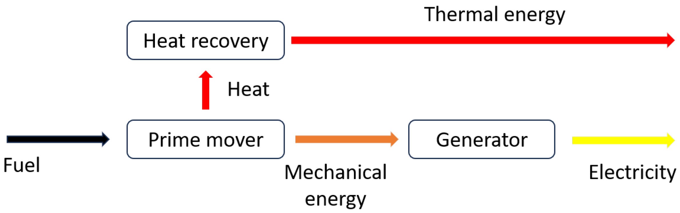
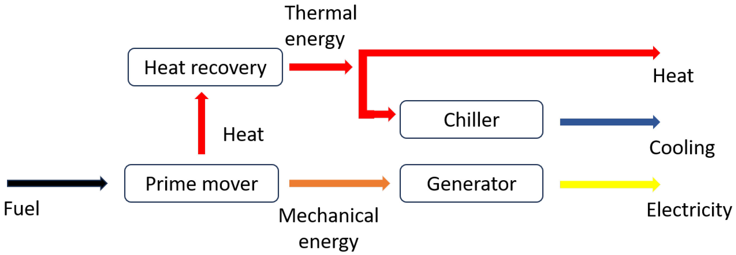
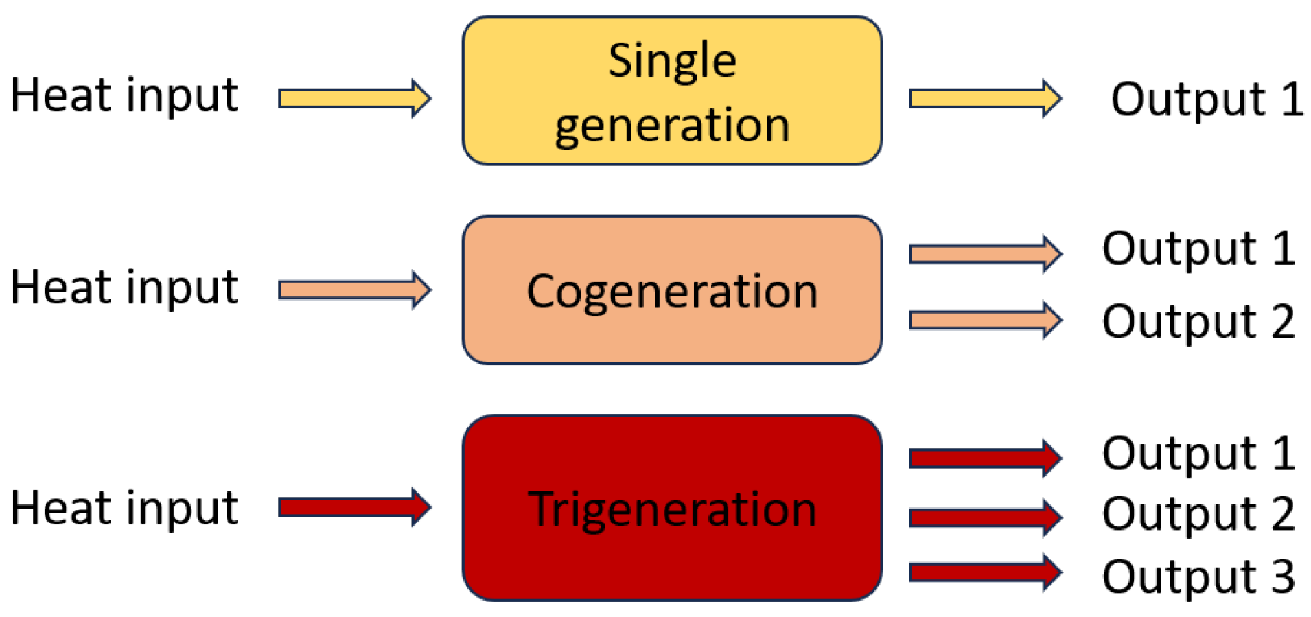
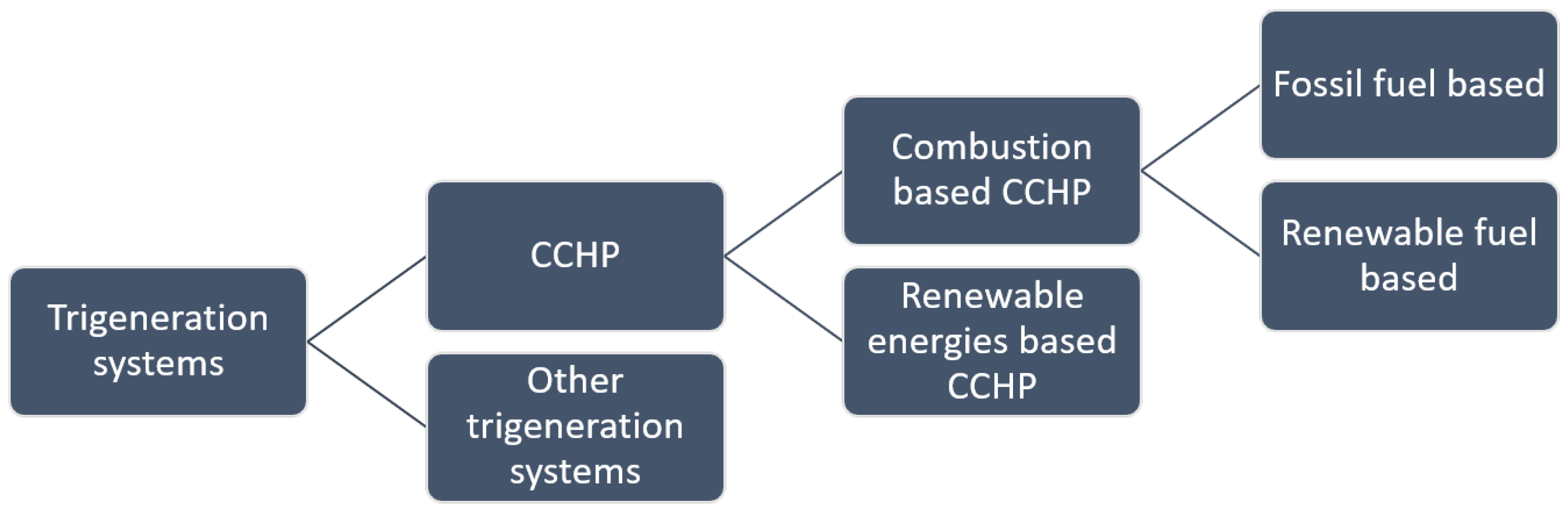
2. Usual Components Depending on the Type of Trigeneration System

As seen in Figure 4, trigeneration systems are not necessarily CCHPs. Other useful outputs can be considered than cooling, heating, and power generation. In this review, trigeneration systems that are not CCHPs will be considered as other multi-generation systems. The heat energy can come from either combustion or renewable sources, such as solar or geothermal sources [16,17,18]. As for the combustion process, this can be done with biogas or other types of renewable fuels.
Biogas as an example is the result of anaerobic digestion, the process through which biomass is transformed into gas in an environment deprived of oxygen. The resulting gases form biogas; a mix mainly composed of methane (CH4) and carbon dioxide (CO2). Biogas can then be refined in biomethane. Biofuels are the result of fermentation, where the sugars of the biomass are turned into alcohols. Bioethanol is the main biofuel produced through this process. Biomass gasification is especially considered as a promising way of producing sustainable fuels. The process of biomass gasification involves heating previously dried biomass to high temperatures (between 750 °C and 1000 °C) in a low-oxygen environment. The resulting gases are a mix of H2 and CO, often called syngas (synthetic gas). The last process of production generally involves cleaning the syngas to remove the potential impurities and solid particles [19,20]. A high-value by-product of biomass gasification is biochar, praised due to its effective use in agriculture. The process of gasification and its applications are further described in [21,22,23,24,25]. That said, fossil fuels are still commonly used. Regardless of the heat source generation, CCHPs and other multi-generation systems typically consist of several basic components in order to generate their different outputs. These components are prime movers, electricity generators, heat exchangers, and thermally activated systems (chillers, etc.). Prime movers convert the thermal energy coming from the heat source into mechanical energy. They are the most important part of a multigeneration system, as they determine to some extent the thermal availability for the other useful effects [26,27]. Both high and low-temperature-based prime movers are described in the following sections. Table 2 provides an assessment of CCHP systems depending on the type of prime mover considered.

2.1. Combustion Based/High-Temperature Prime Movers

Internal Combustion Engines (ICEs) are thermal engines in which the expansion of the gases produced by combustion generates mechanical energy that can be used to generate electricity. The heat from the exhaust gases or from the fluid used to cool the engine (“jacket water”) can be recovered and used as a source for thermally activated equipment. This technology has been shown to offer high reliability, low investment costs, and fast start-up capability [1,2,28]. A variety of fuels can be used, from traditional fossil fuels to renewable or plant-based fuels [2]. This type of prime mover is still investigated, with numerous authors considering ICEs as the prime mover of their trigeneration systems [7,8,9,10,11,29,30,31,32,33,34]. However, ICEs still have some unresolved drawbacks, such as high emissions, noisy operation, and frequent service intervals [1,2,28]. ICEs also tend to suffer damage when used with low-quality fuels [35,36].
Gas turbines also are thermal engines in which the expansion of hot gases drives a turbine, from which the rotary motion can be used to generate electricity. Fuel flexibility is good, as a wide variety of fossil or renewable fuels can be used. This technology is mature, reliable, and emits less GHG than reciprocating internal combustion engines. However, investment costs are on the higher side [28]. Heat recovery is made possible by using the heat from the hot exhaust gases. Micro-turbines use the same working principle but on a smaller scale. The possibility of having external combustion means that low-quality fuels can be used without clogging and damaging the internal parts, as opposed to ICEs [2]. The following studies make use of gas turbines in their CCHP configuration [37,38,39,40]. Micro-turbines are investigated in several studies as well [41,42,43,44]. Steam turbines have a similar working principle as gas turbines, yet the production sequence is fundamentally different. In gas turbines, the electricity production is the main product and the remaining thermal energy is used for other purposes. This is called a topping cycle. In steam turbines, electricity is a by-product of heat production, as vapor is produced first. This is called a bottoming cycle. Steam turbines have been in use for decades in energy production. Fuel flexibility is very high, as the boiler can be used with a variety of fossil and renewable fuels. Greenhouse gas emissions are in turn directly related to the fuel used. Although very reliable, steam turbines are considered to have low electrical efficiency and a long start up time, which can be detrimental in small-scale applications.
As opposed to ICEs, Stirling engines are external combustion engines [45]. Three different configurations of Stirling engines exist, namely alpha, beta, and gamma, with the latter considered to have the highest mechanical efficiency [46]. A variety of working fluids is also available, with helium or hydrogen often being chosen [47]. Just like other combustion-based prime movers, a wide variety of fuels can be used, both fossil and renewables. Wood pellets [48] or solar energy can also be considered [49], and the external combustion process even allows for hybrid solar/combustion layouts [50]. Stirling engines are also reported to have a quieter and lower-emission operation than their internal combustion counterparts [51]. These qualities have made Stirling engines an interesting choice for micro-scale cogeneration systems for residential applications where low emissions, noise, and vibration with high fuel flexibility are key aspects [52,53]. Despite this, the use of Stirling engines in CCHP systems is hindered by high development costs and low power generation efficiency [2,54,55]. Several authors have investigated Stirling engines performance for trigeneration systems [56,57,58,59,60].
Fuel cells convert the chemical energy of a fuel into electricity and heat [61]. Both hydrogen and typical hydrocarbons, fossil and renewables, can be used as fuels. Fuel cells are categorized into five groups: alkaline fuel cells (AFCs), phosphoric acid fuel cells (PAFCs), molten carbonate fuel cells (MCFCs), proton exchange membrane fuel cells (PEMFCs), and solid oxide fuel cells (SOFCs), with the latter two being investigated the most. Several authors have considered SOFCs as the prime movers of their biogas-based trigeneration systems [62,63,64,65,66,67]. Indeed, SOFCs operate at high temperatures, often exceeding 600 °C, which allows for high amounts of heat to be recovered and used for thermally activated equipment. PEMFCs operate at lower temperatures than SOFCs (between 30 and 100 °C) and have a fast start-up time but necessitate expensive materials [68]. Several studies have investigated the use of PEMFCs in CCHP systems [69,70,71,72]. Overall, fuel cells offer high reliability, low noise, and efficient energy production but are still expensive because of the expensive materials needed to make them work or the need for materials that can withstand the acids used in some of them [55,73,74].

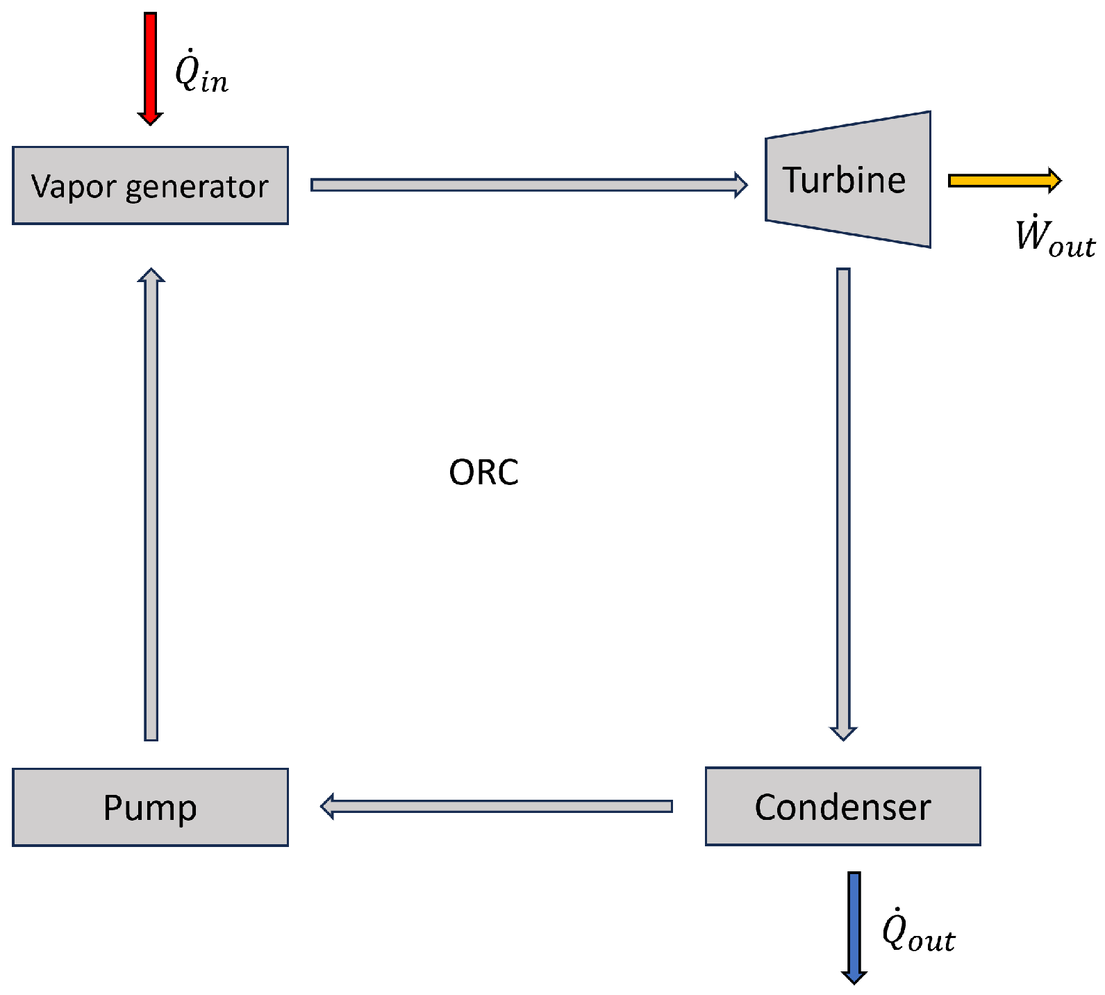
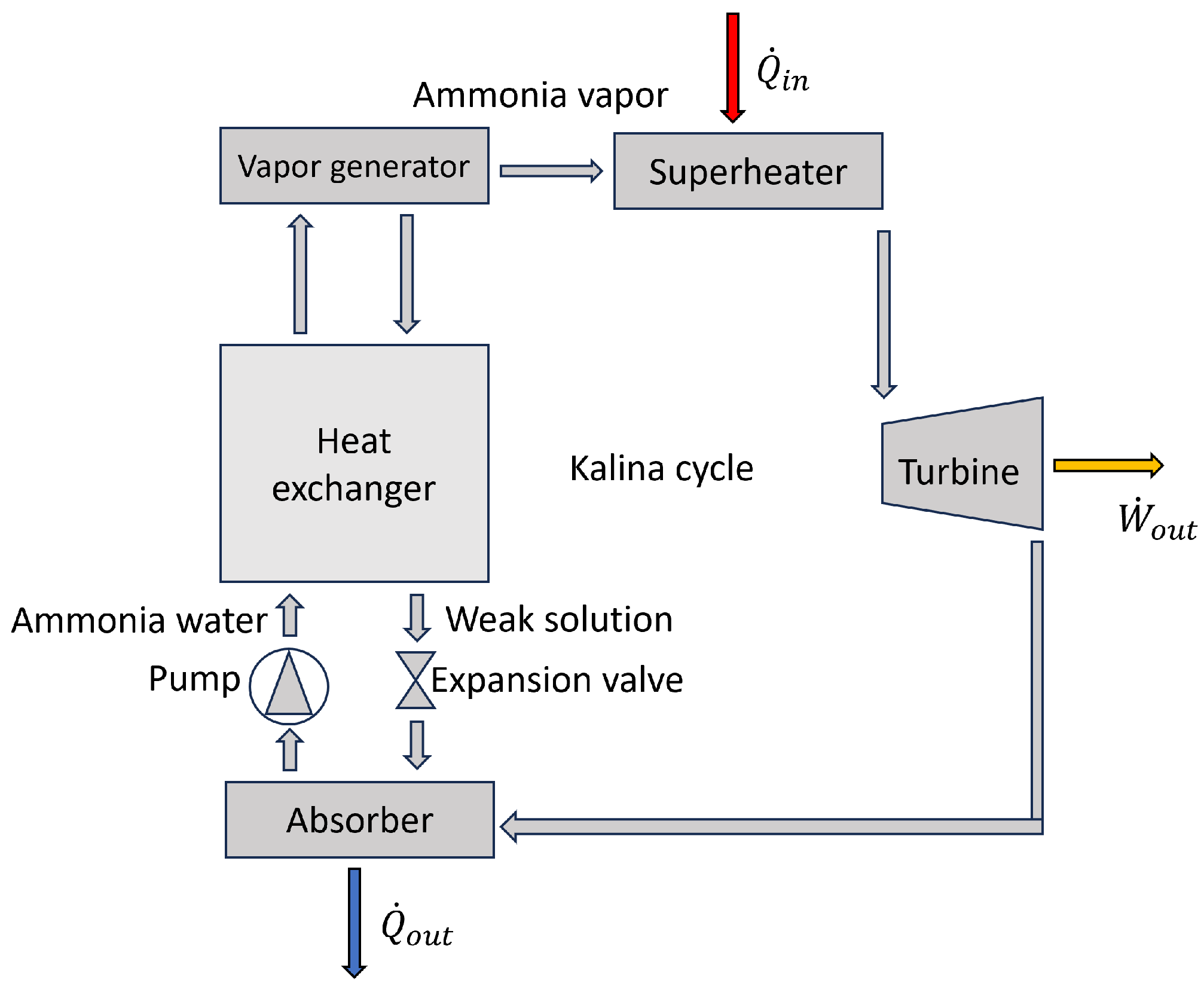
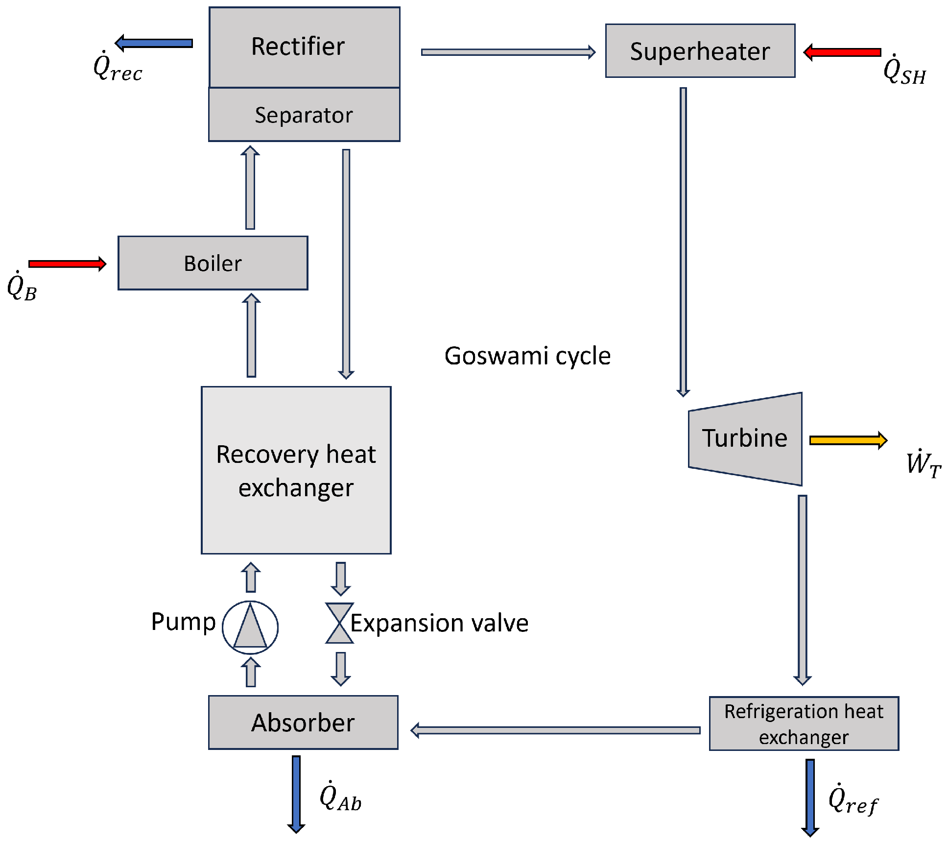
2.2. Low-Temperature Prime Movers

Because of the lower temperatures inherent to some heat sources, different prime movers are required in order to convert the heat into mechanical energy. Several thermodynamic cycles converting heat to mechanical energy exist, such as Rankine (Figure 5), Kalina (Figure 6), and Goswami (Figure 7) cycles.
A Rankine cycle is a closed-loop system that converts heat energy into mechanical energy. It is the most known and used cycle for electricity generation. A typical Rankine cycle is known as the Steam Rankine Cycle (SRC), using water as a working fluid. This cycle is typically found in steam turbines and usually requires combustion to reach a usable temperature. For fuel-free prime movers, an ORC (Organic Rankine Cycle) is commonly used, where an organic fluid is used instead of water. Organic fluids are heavy compounds with large molecular weights and low boiling temperatures and pressures [75]. The main benefit of this thermodynamic cycle is its ability to be used with internal or external combustion systems, and generally with any type of heat source [76]. ORCs can be used with lower temperature sources; thus, the first law efficiency of SRC tends to be higher than with an ORC [77]. Regardless of the working fluid chosen, a Rankine cycle consists of four components: a pump, a boiler, a turbine, and a condenser. The working fluid in liquid phase is pumped to the boiler, where it turns into steam. The high-pressure steam enters a turbine, where it expands, producing mechanical energy before entering the condenser and going back to the pump. The steam can be superheated to prevent condensation on the turbine’s blades, which can be detrimental to the electricity production. The use of dry organic working fluid allows systems to work without the superheating stage, as the expansion process ends in the superheated vapor region [78]. A study on ORCs’ optimization can be found in [79]. ORCs have been extensively considered as prime movers in CCHP systems. Research on different working fluids has been proposed in order to enhance performance and decrease environmental costs. Khan et al. [80] notably mentioned that R134a has better alternatives, including R290 and R1233zd.
A Kalina cycle is similarly used to produce mechanical energy using a low-temperature heat source. Improving the exergy efficiency of a steam Rankine cycle pushed Kalina et al. to develop this thermodynamic cycle [81]. Compared to Rankine cycles, which use either water or an organic working fluid, a Kalina cycle uses a mixture of ammonia ( N H 3 ) and water. This cycle has been considered both for cogeneration and for trigeneration [82]. Different Kalina cycle configurations have been investigated depending on the specific application [83,84,85,86]. In the heat recovery unit, the mixture of water and ammonia is separated. Because of the lower boiling point of ammonia, ammonia vapor is formed and is superheated before entering the turbine, where its expansion converts the thermal energy into mechanical energy. A generator then converts it into electricity. After leaving the turbine, the low-temperature vapor is mixed with the weak solution: the mixture of water and ammonia that has not evaporated. The mixture regains its initial concentration and is pumped back to the heat recovery where the cycle begins anew [81,87]. It is investigated in CCHP systems in [88,89,90].
A Goswami cycle is a modified Kalina cycle, as it combines the working principle of the latter, coupling it with an absorption refrigeration process [91]. In a similar manner to a KC, the ammonia and water mix is preheated by the weak solution going to the absorber. After being preheated, the mix is partially boiled to produce a two-phase mixture. The vapor with high ammonia concentration enters the rectifier after the remaining liquid is removed in the separator. The rectifier condenses out any remaining water, and almost pure ammonia vapor is superheated before entering the turbine. The expansion process produces mechanical energy. The vapor exiting the turbine then enters the refrigeration heat exchanger, where sensible heat exchange provides the cooling generation. The cold ammonia mixture lastly enters the absorber, where it is absorbed by the weak solution. The mixture regains its initial concentration and is pumped back to the heat recovery exchanger. Extensive research has been conducted in order to enhance this cycle’s operation. Because of the desired low vapor temperature required for cooling generation, which is detrimental to power production, a study shows that a heat source of 87 °C allows for optimum production of the two useful effects. It is reported that heat sources hotter than 167 °C would result in an absence of cooling generation [92]. This is present in the following studies [93,94,95].
Table 2. Assessment of CCHP systems depending on the type of prime mover used.
Prime MoverReferences
ICE [7,8,9,10,11,29,30,31,32,33,34]
GT [37,38,39,40]
Microturbine [41,42,43,44]
Stirling engine [56,57,58,59,60]
Fuell cells [62,63,64,65,66,67,69,70,71,72]
ORC [60,96,97]
KC [88,89,90]
GC [93,94,95]

2.3. Prime Mover Combinations

A vast majority of CCHP systems only feature a single prime mover in order to maintain low initial investment costs. However, several studies shed light on system layouts making use of a combination of prime movers. This allows for better use of the thermal energy released during the combustion in or before the first prime mover, or better fuel usage.
Several hybrid systems combining ICEs with other heat sources have been envisioned. Yousefi et al. [98] presented a solar-assisted CCHP system, coupling an ICE with Photovoltaic/Thermal (PV/T) panels. This study showed that although the initial investment cost was higher for a solar-assisted system than for a single ICE prime mover, the former had better performance in energy savings and lower GHG emissions. The reduction in CO2 emissions was reported to be twice as much for the solar-assisted system than for the single ICE system. PV/T panels could reach as high as 3.2% and 14.5% of the annual electric and heat load of the building, respectively. Ma et al. [15] proposed an hybrid ICE and solar system that also uses a heat pump and thermal storage. The fuel used for the ICE is syngas, produced by gasifying wood chips. A CCHP system combing a 1 MW gas turbine with a 1MW diesel ICE was proposed by Abbasi et al. [99] in which a single-effect LiBr-water absorption chiller was used as thermally activated cooling equipment and an auxiliary boiler was used to provide the rest of the building’s heating demands. The system’s energy efficiency with two prime movers was reported to have increased up to 10% compared to that of a single prime mover. Exergy efficiency also increased, reaching 62.8% for the best hybrid system compared to the value of 45% attained using a single gas turbine prime mover. Operating cost reduction reached 80%, along with a shorter payback period.
Numerous authors have proposed CCHP systems coupling SOFCs with gas turbines [100,101]. In these systems, the goal is to use the unreacted gases exiting the fuel cell and combust them in the gas turbine in order to produce more electricity and to have better fuel usage. Huang et al. [102] recently proposed a configuration in which the exhaust gases of the fuel cell, mainly consisting of unreacted fuel and air, are combusted in an afterburner before entering the gas turbine. The exhaust of the gas turbine is then used to drive the thermally activated equipment responsible for producing the other useful effects. Three different subsystems, namely a Rankine cycle, a hybrid organic Rankine cycle/steam ejector refrigeration, and a heat exchanger to produce domestic hot water, were positioned after the gas turbine, making use of the cascading thermal energy available after the combustion. In this study, the energy, electrical, and exergy efficiencies of the system were reported to be 78.55%, 65.73%, and 61.20%, respectively. Chen et al. [103] proposed a configuration attaining an energy efficiency of 61.9% and a fuel utilization factor of 0.75. Huang et al. and Dong et al. [104,105] proposed similar configurations, with energy efficiencies and fuel utilization factors ranging from 61.1% to 72% and from 0.75 to 0.85, respectively. Velumani et al. [42] proposed a system combining a micro-turbine and a SOFC, which reached 70% thermal efficiency. Khan et al. [80] proposed further enhancement of the SOFC-GT combination by proposing to add an ORC in series with the fuel cell and the gas turbine. The addition of this technology and of a cascaded vapor absorption refrigeration system (VARS) and vapor compression refrigeration system (VCRS) improved energy efficiency, exergy efficiency, power output, and total cost by 34.88%, 9.41%, 6.58%, and 11.71%, respectively, a well as decreasing CO2 emission per MWh of energy output by 25.85%. This system is reported as a better alternative both energetically and environmentally than traditional SOFC-GT systems.
The combination of SOFC and ORC was also studied by Al-Sulaiman et al. [106], where the system reached a trigeneration efficiency of 74%, cooling cogeneration efficiency of 57%, and heating cogeneration efficiency of 71%. Other examples can be found in [80,96,107].
A combination of different fuel cells can also be a solution to make use of the thermal and chemical energy still available exiting a SOFC. Several studies used a combination of SOFC and PEMFC rather than a gas turbine to use the excess fuel exiting the SOFC. In a study by Zhang et al. [108], a system combining a SOFC and a high-temperature PEMFC is proposed. In this system, biomass is gasified to produce syngas, which after being cleaned of its impurities is used in the SOFC. The cathode exhaust gas from the SOFC provides waste heat to an ORC system. Unreacted gas is further processed to produce carbon dioxide and hydrogen. Hydrogen from unreacted gas is purified and used in a HT-PEMFC for electricity generation. Cooling, domestic hot water, and electricity productions of the proposed system are 435 kW, 699 kW, and 1394 kW, respectively. System energetic efficiency is 49.48%, and exergetic efficiency reaches 25.06%.
You et al. [109] proposed a novel layout of SOFC and solar energy combination.
Chahartaghi et al. [110] proposed a CCHP system with two beta-type Stirling engines in parallel as prime movers. The values for the electrical efficiency and trigeneration efficiency were 27.31% and 74%, respectively. Chahartaghi et al. [111] also proposed a CCHP system with a hybrid solar microturbine as a prime mover for building applications. The authors reported the efficiency of the electricity generation to be approximately 20% and the CCHP efficiency to be around 55%. A combination of Stirling engine and ORC can be found in [60].

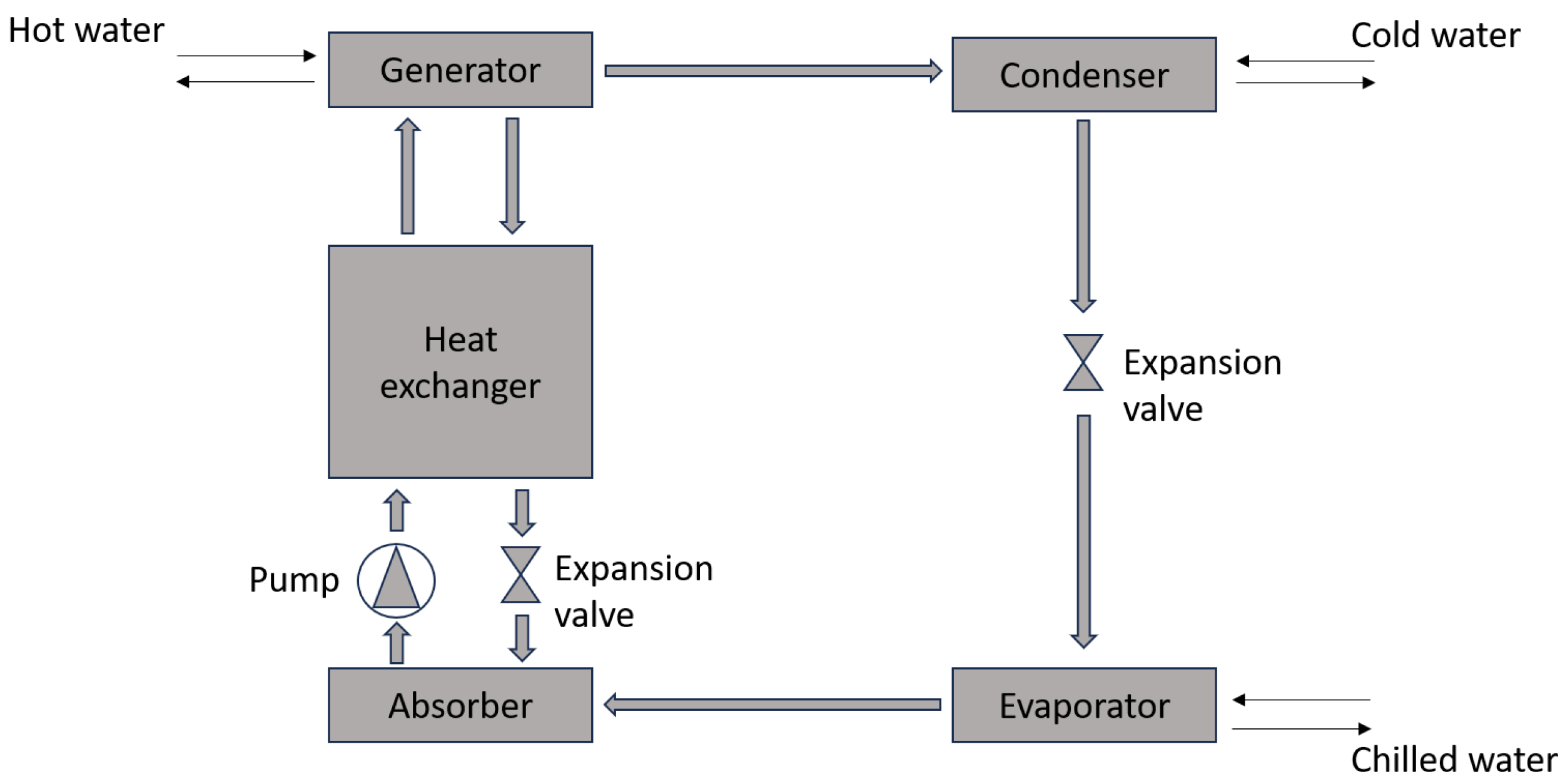
2.4. Cooling Systems and Thermally Activated Equipment

Cooling is usually provided by vapor compression systems. Such systems require high amounts of electricity to work and do not utilize renewable heat or waste-heat energy. Although being the most widely used refrigeration system worldwide, it is necessary to increase their efficiency or to use other, more performant, quieter cooling systems [112,113,114,115]. The use of thermally activated cooling rather than conventional compression units is what allows CCHP systems to have overall good energy and exergy efficiency, as heat exiting the prime mover can be used rather than released to the atmosphere. Absorption chillers (Figure 8) are heat-driven cooling systems. Such systems are able to use waste-heat from industrial sites as well as renewable heat sources and are considered better alternatives than vapor compression systems when heat is readily available [116]. Therefore, they are the most widely used cooling unit found in CCHP systems, regardless of prime mover used. The main difference between the working principles of VCS and ACs is that the vapor compressor is replaced by an absorber, a pump, and a generator. The use of a pump rather than a compressor allows for high electricity savings. The working fluids also are different, with ACs commonly using water/NH3 and LiBr/water as absorbent/refrigerant couples. Other working mixtures exist [117], and a review on the influence of nanoparticles on AC performance can be found in [118]. Absorption chillers are tri-thermal thermodynamic cycles; a “high” heat source (around 85 °C) allows the working fluid to evaporate, cooling is produced (around 5 °C), and heat (around 35 °C) is rejected. The more detailed working principle, similar to the KC (Kalina Cycle) or GC (Goswami Cycle), is as follows: the strong absorbent/refrigerant mixture is pumped to the generator and preheated in the solution heat exchanger by the weak solution. The weak solution is the low-refrigerant mixture that flows from the generator back to the absorber.The mixture heated in the generator releases refrigerant vapor, which is then cooled in the condenser. Heat is released to the environment or to an external fluid, and the refrigerant vapor is converted into a liquid state. The saturated refrigerant liquid expands through a valve, decreasing its pressure to the evaporator pressure, then it enters the evaporator. Heat is absorbed from the external fluid, turning the refrigerant back into vapor and producing the cooling effect. The refrigerant vapor leaving the evaporator enters the absorber, where it is mixed with the weak solution coming from the generator. The strong absorbent/refrigerant solution is regenerated and is pumped to the solution heat exchanger, closing the cycle [119]. As mentioned earlier, it is extensively used in CCHP systems [72,96,120,121].
Adsorption chillers are different from absorption units in several ways. Adsorption chillers use an adsorbent/adsorbate couple, with the adsorbent being a solid bed that is able to absorb and desorb the refrigerant, as opposed to the liquid state of the mixture found in absorption chillers [122]. Adsorption units are reported to be quiet, low-maintenance, and able to work with lower heat sources than absorption machines, making them an interesting prospect for residential micro-scale CCHP units [2,123,124]. An adsorption cycle works as follows [125]. In the desorption stage, hot water enters the first compartment, heating the solid adsorbent bed. Refrigerant vapor is released and enters the condenser, where it is cooled and liquefies. This low-pressure liquid refrigerant is sprayed in the evaporator, where the cooling effect is produced. Water gives its heat to low-pressure liquid refrigerant, vaporizing it. The refrigerant vapor enters the second compartment, where it is absorbed again and saturates the solid adsorbent. Different adsorbent/adsorbate pairs are used in various adsorption technologies, the most commonly used being the silica gel–water pair. This technology works with a heat source temperature below 100 °C, which makes it very appropriate for CCHP systems based on renewable energies as well as their absorption counterparts [97,126,127]. Heat pumps can also be considered as cooling equipment [119,128]. A reversible heat pump could use the waste heat from a prime mover as a heat source and provide cooling using electricity produced by the prime mover [129]. Such systems have been investigated with different renewable sources, mainly solar and geothermal [130,131,132]. Heat pumps can also be used to provide heating when the thermal energy recovered from the prime mover is not sufficient to meet the heating requirements [133]. Ejector cooling is another alternative to available cooling systems. The lack of moving parts allows for both low investment and maintenance costs [51], more specifically, lower costs than absorption chillers [134,135]. An extensive review of these systems can be found in [136]. Therefore, several studies use such systems for their CCHP configurations. Moghimi et al. [137] and Sadeghi et al. [138] both used ejector refrigeration systems. Saladi et al. [139] investigated a solar integrated ejector-based CCHP system and its performance in different climates encountered in India.

2.5. Other Multi-Generation Systems

Some trigeneration systems are not CCHP because one or more useful effects are different from those of a typical CCHP system. These systems are a type of multi-generation system, still producing three different outputs from a single heat input, but with different types of useful effects. The most common are hydrogen and fresh water production. In countries where one effect of a typical CCHP system is not as needed, having another type of useful effect can allow for better use of waste heat and overall efficiency. It is also reported that having other marketable effects (hydrogen, fresh water, etc.) can allow for a shorter payback period than traditional CCHP systems. In some cases, more than three useful effects can be simultaneously generated. These systems are called multigeneration systems and are an enhanced form of trigeneration. These systems are often traditional CCHP systems that will use a proportion of the electricity, cooling, or heating generated as a resource for another useful effect [140]. As mentioned earlier, hydrogen [141,142,143,144] and potable water [145,146,147,148,149] are the most frequently encountered useful effects that differ from traditional trigeneration systems. Some trigeneration systems even combine water and hydrogen production [36,150]. That said, other useful effects can be considered depending on the needs of the end user. Systems including production of ice [151], dried food, and ice [95] or methanol [152] have been described in the literature.

3. Performance Indicators

Several performance indicators may be used when studying a multigeneration system. The following parameters can be used to evaluate a CCHP’s system performance and its different components. As a whole, complete analysis of a system with these different performance indicators is referred to as 4E analysis in the literature [120,137,153,154,155].

3.1. Energy Efficiency

Based on the first law of thermodynamics, energy efficiency is the ratio of net energy output to gross energy input. Due to the losses present in all components, there is a difference between the amount of energy entering and leaving a given component. When considering the energy efficiency of a system, these losses must be taken into account. Therefore, the energy input must be considered before these losses (gross input), while the energy output must be considered after these losses (net output). As seen before, the energetic efficiency is the ratio between the net energy output and the gross energy input. For a generator as an example, it would be as follows:
η g e n e r a t o r = W ˙ e l e c Q ˙ i n p u t
As seen before, the energy efficiency measures the relationship between total energy inputs and useful energy outputs calculated over a predetermined time interval. For a CCHP system, it is as follows:
η o t r i g e n e r a t i o n = W e l e c + Q h e a t i n g + Q c o o l i n g Q i n p u t
The following formula is commonly found in the literature to calculate instantaneous energy efficiency using energy flows [82]:
η t r i g e n e r a t i o n = W ˙ e l e c + Q ˙ h e a t i n g + Q ˙ c o o l i n g Q ˙ i n p u t
As the efficiency is not suitable for machines producing more energy than they consume, COP (Coefficient Of Performance) is the parameter used to assess a system’s performance. It is the ratio of the cooling energy produced to the amount of work required. For an absorption chiller, COP is as follows:
C O P a b s o r p t i o n c h i l l e r = Q ˙ c o o l i n g Q ˙ i n p u t + W ˙ p u m p
Finally, the Primary Energy Savings (PESs) allows researchers to evaluate the amount of energy saved by using a CCHP system compared to three separate conventional single generation systems. This is further developed in [156,157].

3.2. Exergetic Efficiency

The exergetic efficiency is a meaningful performance indicator, but due to the different nature between the power and thermal outputs, an exergetic approach is often also needed. It is also commonly known as exergy efficiency. Indeed, exergetic performance indicators allow for a better comparison between systems regardless of their temperature levels. In a similar manner to energy efficiency analysis, the amount of exergy entering a given component system or component is equal to the amount of exergy leaving it and the amount of exergy lost in the process (Figure 9).
E x ˙ i n = E x ˙ o u t + E x ˙ D
The exergy balance of the system is as follows:
d E x d t = E ˙ x Q T + W ˙ + p 0 d V d t + m ˙ i n e x i n m ˙ o u t e x o u t + T 0 S ˙ i r r
where e x i = ( h i h 0 ) T 0 ( s i s 0 ) is the physical exergy and E ˙ x Q T is the exergy of heat:
E ˙ x Q T = 1 T 0 T Q ˙
In some studies, the chemical exergy in each point of the system is also considered. The amount of exergy in any point is therefore the sum of the physical and chemical exergy at this given point. The exergy efficiency of each component of a system can be obtained by first defining the amount of exergy entering (fuel), leaving (product), and destroyed in each component.
The exergetic efficiency is as follows:
η e x = P r o d u c t F u e l = E ˙ x P E ˙ x F
The exergetic efficiency for a CCHP is therefore given by the following equation:
η e x , C C H P = E ˙ x e l e c + E ˙ x h e a t i n g + E ˙ x c o o l i n g E ˙ x F

3.3. Economic Performance

Optimizing a CCHP system is not just a matter of finding the best technical performance. It also requires an economic analysis. The development of thermo-economic analysis makes it possible to optimize these factors simultaneously. More specifically, exergo-economic analysis allows the exergy analysis to be related to the economic constraints encountered when optimizing the performance of a complex thermodynamic system. For each component, an exergo-economic balance can be written, which makes it possible to relate the cost of the component to the cost per second of the flows necessary for its operation. It can be written as follows:
c o u t E ˙ x o u t + c W W ˙ = c i n E ˙ x i n + c Q Q ˙ + Z ˙
The investment cost of a component, Z, is a one-off cost that can be converted into an annual cost using the capital recovery factor (CRF):
C R F = i ( 1 + i ) N ( 1 + i ) N 1
with i the interest rate and N the expected number of years of the system’s life. Thus, the hourly investment cost can be expressed as follows, where ϕ is the maintenance factor and N is the number of yearly operating hours:
Z ˙ = Z · C R F · Φ N
As mentioned before, Z represent the investment cost of a given component. This cost depends on its complexity and different intrinsic characteristics (efficiency, area, area of reference, power, etc.). Some examples are given below [158]:
Z j = Z R j A j A R 0.6 Z t u r b i n e = 4750 ( W ˙ t u r b i n e ) 0.75 + 60 ( W ˙ t u r b i n e ) 0.95 Z p u m p = Z R j W ˙ p u m p W ˙ R , p u m p 0.26 1 η η 0.5
The Levelized Cost Of Energy (LCOE) is defined as the ratio of the cost of producing a unit of energy (€/kWh) from an energy source to the energy production of this source over a given period of time (one year, the life of the project, etc.). This concept can be generalized to other polygeneration concepts and products: levelized cost of electricity production (LCOP), levelized cost of electricity (LCE), and levelized cost of green hydrogen (LCOH) or ammonia (LCOA) are indicators found in the literature [159,160,161,162].
The same principle can also be applied to exergy costs, such as in [163]. In this article, LExCOE (Levelized Exergy Cost Of Electricity) is defined as the exergy invested throughout the lifecycle (including fuel and infrastructure) to deliver a unit of electricity.

3.4. Environmental Performance

The combination of exergy, environment, and life cycle analysis (LCA) is called exergoenvironmental analysis and aims to determine the environmental impacts of the components, fuel, and products in use or created in the studied system [158,164,165,166,167].
The environmental impact balance of a system’s k-component in terms of product B P , k and fuel B F , k can be written as follows:
B P , k = B F , k + Y k + B k P F
with Y depending on a lifetime of environmental impacts for a given component at different stages of its use, including manufacturing, transport and installation Y C O , k , operation and maintenance Y O M , k , and disposal Y D I , k For a given kth component, Y can be calculated as follows:
Y k = Y C O , k + Y O M , k + Y D I , k
B k P F is used to evaluate the pollutant formation in a given component. It is only needed when components release GHGs (Greenhouse Gases), which typically occurs in a combustion process, but its value is zero in combustion-free processes like compression or heat transfer. Considering the corresponding environmental impacts per unit exergy of fuel b F , k and product b P , k , Equation (12) becomes:
b P , k E x P , k = b F , k E x F , k + Y k + B k P F
Thus, an exergoenvironment factor can be calculated as follows:
f b , k = Y k Y k + b F , k E x D , k
The exergoenvironmental analysis can also be considered through the prism of exergodestruction, which aims to determine the impact of irreversibility to the environment. This is developed in a study by Zhang et al. [168].
Following the same principle as PES, avoided GHG emission (AGE) analysis aims to determine the environmental benefits of using a CCHP system over three separate conventional single generation systems. An example of the use of this indicator is detailed in [169].

3.5. Energy Storage Performance Indicators

The energy density is defined as the energy stored per unit mass or per unit volume of the energy storage system. It is a key technical performance indicator of an Energy Storage System (ESS) [170].
Round Trip Efficiency (RTE) is the ratio of the energy output (retrieved after it has been stored in the ESS) to the energy input. It is also a key performance indicator, as higher values indicate smaller losses. It varies significantly depending on the type of ESS used [171].

4. Comparison Between Different Plant Configurations and Technologies

4.1. Combustion Prime Mover Comparison

Extensive research has been carried out to assess CCHP system performance based on the prime mover used. However, no research has been found on the optimization of different CCHP plant configurations depending on the prime mover used. This may be due to the wide variety of technologies, fuels, applications, and scales available regarding trigeneration systems. Despite this, key takeaways can be identified based on existing prime mover comparisons.
The use of the ICE as a prime mover is praised in many studies, both for its performance and its cost efficiency. Ebrahimi et al. [43] compared the performance of ICEs, Stirling engines, and gas micro-turbines for a micro-scale CCHP system in Iran. Several scenarios were used following different climates that could be encountered in the region. The authors recommended using ICE as the main prime mover to build a micro-CCHP for residential buildings in the five climates. It has to be noted that fuel cells were not studied in these scenarios because of the unavailability of this technology. Roman et al. [44] studied the performance of reciprocating internal combustion engines (ICEs), micro-turbines, and phosphoric acid fuel cells (PAFCs) in a climate similar to the conditions found in Chicago, USA. This study aimed at finding the best prime mover for a medium-sized office building with an operational strategy and did not consider power storage or the ability to sell back electricity. The system would only have a single prime mover. The results showed emission reductions for all three types of prime movers compared to the separate, single generation of heating and power in the reference building. The greatest reduction encountered was from the ICE, followed by the fuel cell, then the micro turbine. Prime energy consumption was also shown to be reduced for all three cases, with the greatest reduction from the fuel cell, followed closely by the ICE, then the micro turbine. Economic considerations, however, indicate that the fuel cell PM would not be feasible for that building in this climate. The ICE would have the best economic savings, followed by the micro-turbine.
When comparing gas engines and gas turbines of the same power, Li et al. [172] reported that the fuel energy saving ratio (FESR) of CCHP systems based on gas turbines is lower than that of gas engines. The same comparison was made by Arcuri et al. [173]. Methane-fueled internal combustion engines were compared to simple cycle gas-turbines with the goal of finding the best prime mover for a CCHP system to be installed in a 930-bed hospital. The authors reported engines to be more cost-effective than gas turbines in both short and long-term analyses.
In contrast to the studies presented before, some research indicates that ICEs are not always the best prime mover available for CCHP systems. Depending on the scale, fuel, and performance indicator used, other technologies may be better suited. A recent study by Lucarelli et al. [13] compared the performance of ICEs, PEMFCs, and SOFCs as prime movers for a CCHP system meeting the needs of a large industrial user. The average electrical load in the four reference periods for this case study is equal to 4970 kW, the average thermal load is equal to 4370 kW, and the average cooling load is equal to approximately 410 kW, while the maximum cooling load is relative to the summer reference period and is approximately 780 kW. Internal combustion engines fueled by methane are reported to be the most convenient technology from an economic–financial point of view. However, when considering not only the economic–financial aspects but also the environmental impact and technological efficiency, SOFCs were chosen as the prime mover. SOFCs were reported as the most efficient prime movers in all cases studied, with PEMFCs reported by the authors as the most promising technology in terms of environmental performance when used with green hydrogen.

4.2. Comparison of Plant Configurations for Low-Grade Heat-Based Prime Movers

Because of the lower temperature heat source, geothermal and other low-temperature-based prime movers systems must be optimized differently than systems using combustion-based prime movers. Generally speaking, renewable energy-based CHP and CCHP systems are either in series or in parallel. In series, the hot fluid from combustion, Carnot battery storage, etc., passes through different heat exchangers, one after the other. For example, the fluid first passes through a heat exchanger in an ORC machine, where its heat is used to vaporize the working fluid. It is then sent to other exchangers to generate heat, and then to an absorption machine if the temperature level is high enough. If the hot fluid is separated into two separate flows after the prime mover, to supply a district heating network and an absorption machine simultaneously, for example, this is referred to as a parallel system. However, more complex systems combining series and parallel are frequently studied in the literature. In the following study, different systems will be presented in order to determine the most suitable geometry for low-heat renewable sources.

4.2.1. Serial Systems

The most technically and economically interesting cogeneration systems generally have a series configuration, or one derived from a conventional series configuration. Both Habka et al. and Van Erdeweghe et al. proposed extensive research on the subject [174,175,176,177,178,179,180,181]. Van Erdeweghe et al. [174] reported that the series CHP is generally the optimal CHP configuration.
Multigeneration systems—more specifically, low-temperature-based CCHP systems—are therefore initially envisaged in series. The hot fluid coming from the heat source passes through different heat exchangers, one after the other. In the case of CCHP trigeneration, the first component to receive the heat is usually the prime mover in order to maximize electricity production by ensuring that the heat engine receives the hottest fluid possible (Figure 10).
In the different systems described by Pastor-Martinez et al. [88], the hot fluid from a geothermal source (geothermal brine) is first supplied to the ORC system, where some of its heat is released to vaporize the working fluid. It is then sent to an absorption machine or a district heating generator, the third component being the one that has not been positioned in the second position. The impact of this choice is of course decisive in the overall efficiency of the trigeneration system. In the simplest system (SC1), the thermal energy is used in cascade: the geothermal brine flow is never separated and passes in its entirety through each component of the system. The production of heating and cooling depends on the temperature of the fluid leaving the ORC. In this configuration, electricity production is maximized, potentially to the detriment of other useful effects. This configuration has the best exergy efficiency of the eight systems presented in this article, for a brine temperature of between 100 and 150 °C. In the SC2 configuration, the hot fluid is separated into two identical flows, going to the ORC system and the absorption machine, respectively. The fluid leaving the ORC is reintegrated into the flow entering the absorption machine, so that all the geothermal fluid passes in series through the last two components of the system. In this configuration, thermal production still depends on the temperature of the fluid leaving the ORC, but electricity production is no longer the main objective. In the SC3 configuration, the fluid is again separated into two identical flows, towards the ORC and the heating generation. Cooling production depends directly on the temperature at the ORC outlet, while heating production depends on the temperature of the mixture between the initial fluid and the fluid leaving the absorption machine. Above 100 °C, this configuration offers the best thermal efficiency, with the best heating output at a temperature of 80 °C. The exergy efficiency of this configuration remains the third best at this temperature level.
The serial concept presented above was also studied by Schifflechner et al. [16]. As before, the fluid from the geothermal source first passes through the ORC cycle before being sent to the desorber of the absorption machine and then to the heat exchanger of the district heating network.
In the second series configuration presented in their study, the order is simply different: the district heating network heat exchanger is placed at the output of the ORC cycle, before the absorption machine. The temperature required for the component in the second position sets the ORC output temperature, and the same applies between the second and third components of the system. The results obtained for the series configurations are similar to those presented by Pastor-Martinez et al., with an exergy efficiency of the complete system of the order of 50%, here for an inlet temperature of 130 °C.
An equivalent configuration is also studied by Zare [82]. This article looks at the performance of two series systems, differentiated by whether they use a Rankine or Kalina cycle to produce electricity. The two systems presented in the study place the absorption chiller in second place, directly following the prime mover.
For this type of series configuration, the use of a Kalina cycle appears to be beneficial. The use of ammonia, which is very harmful, remains an area for improvement. It should also be noted that for both systems (ORC and KC), increasing the temperature of the geothermal brine increases the cold production. However, the presented exergy efficiencies are lower than those proposed by Schifflechner et al. and Pastor-Martinez et al.
The advantages of Kalina cycles in series configurations are confirmed in the study by Ambriz-Díaz et al. [95]. In the polygeneration systems presented in their study, a geothermal source at 135 °C is used to heat water, which is then fed into a thermal machine to produce electricity, followed by an absorption machine. At the end of the cycle, the residual heat is used to dry tomatoes. Although this last application is not common, it is interesting to study the overall efficiency of the polygeneration system as a function of the energy production cycle chosen.
The three production systems studied are the Rankine, Kalina, and Goswami cycles. This study shows that although the electricity production is highest for the system using a Kalina cycle, the best overall energy efficiency is achieved with an ORC cycle. The ORC system is also the most economically viable. However, it is also the least exergy efficient cycle.
Also using a Kalina cycle, the system presented by Mohammadi et al. [89] has a similar configuration to the ‘Serial Concept 3’ described by Pastor-Martinez et al. A Kalina cycle is placed in parallel with a conventional steam cycle, which provides 90% of the total power, and in series with a cooling production cycle. After supplying heat to the Kalina cycle, the geothermal fluid could be used to produce hot water. The energy efficiency of this configuration is about 38%. This system appears to be effective in producing the three desired benefits without using fossil fuels. However, the temperature of the geothermal source is high, around 230 °C.
Another innovative polygeneration system requiring high geothermal temperatures was proposed by Bamisile et al. [90]. The configuration presented is designed to operate with a geothermal resource whose temperature reaches 250 °C. This system can simultaneously produce hot air, hot and cold water, electricity, and hydrogen from renewable resources. The hydrogen could also be used to supply the connected building with energy and cooling at times of peak demand.
In contrast, the system studied by Behnam et al. [182] uses a geothermal source with a temperature below 100 °C; in this case, around 90 °C. It is interesting to note the series connection of an absorption machine followed by an ORC cycle. In this configuration, the exergy efficiency reaches 45%.
The system studied by Al-Ali et al. [183] represents a ’complex’ serial configuration. In this system, the geothermal fluid is mixed with the hot fluid leaving the second ORC cycle. A separator separates the steam from this mixture, which feeds a turbine to generate electricity, from a hot fluid that feeds the first ORC cycle before being reinjected into the geothermal well. On leaving the turbine, the fluid is sent to a heat exchanger to feed a heat network for an industrial process. On leaving the heat exchanger, the fluid is heated by the solar network before entering the second ORC cycle, where it heats the working fluid; in this case, n-octane. This fluid, at the outlet of the ORC turbine, is used to evaporate the steam in the generator of the absorption machine.

4.2.2. Parallel Systems

The first parallel system studied was that of Pastor-Martinez et al. In this configuration, the geothermal fluid is simply divided into three identical streams, each feeding a component of the trigeneration system (Figure 11). This configuration is conceivable if the temperature of the geothermal fluid is sufficient to allow for direct operation of the three thermal machines. The parallel configuration is the one with the lowest efficiency, because the available energy is divided into three equal flows, and the temperature difference between the inlet and outlet of the subsystems is relatively small compared to the other configurations. In fact, this type of system cannot be used in cascade. These conclusions are shared in the study of Schifflechner et al.
At a temperature of 200 °C, the electrical, heating, and cooling powers are 952.3 kW, 1618 kW, and 1896 kW, respectively. The energy and exergy efficiencies are 34.98% and 49.17% for the whole system. In this article, the parallel configuration is the configuration with the lowest thermal efficiency, at 5.8%, whereas the series configurations reach 11.68%. The parallel configuration appears to be contraindicated regardless of the temperature level of the geothermal resource.

4.2.3. Serial–Parallel Systems

The article by Pastor-Martinez et al. also presents four series–parallel configurations (Figure 12). The HSP configuration is a variant of the SC1 configuration, in which the geothermal fluid is first used to produce electricity via an ORC cycle at the first level of the cascade. At the ORC outlet, the fluid is separated into two identical streams, one feeding the absorption machine and the other feeding a heat exchanger for the production of heat. This second stage is used to recover residual heat, as this type of configuration is mainly focused on electricity production. Conversely, the HPS1 configuration is a derivative of the “parallel” concept. In this case, the thermal production is maximized and the electrical production is only complementary. The geothermal fluid is split into two identical streams feeding the heat exchanger and the absorption machine before being combined into a single stream entering the second stage of the thermal cascade in the ORC cycle. The HPS2 and HPS3 configurations are variations of the HPS1 configuration; in HPS2, the heat exchanger and ORC cycle are reversed. Electricity and cooling production are recovered, and the residual heat is used to produce heat at the second level of the cascade. In the HPS3 configuration, the ORC cycle and heat exchanger occupy the first level of the thermal cascade, relegating the absorption machine to the second level.
The study of these systems shows that none of these configurations is as efficient as the SC1 configuration presented above. Some configurations, although interesting for certain applications, never achieve the highest performance in terms of simultaneous production of the three useful effects. Configurations based on heating and electricity production achieve lower results than the SC1 configuration.
Serial–parallel configurations are presented in the article by Schifflechner et al. In the first, the configuration is identical to the HSP system described by Pastor-Martinez et al. The geothermal fluid is first used to produce electricity via an ORC cycle at the first level of the cascade. At the ORC outlet, the fluid is separated into two identical streams, one feeding the absorption machine and the other feeding a heat exchanger for heating. This second stage is used to recover residual heat, as this type of configuration is mainly focused on electricity production.
In the second configuration presented, known as ‘advanced serial–parallel’, the geothermal fluid flow is split after the evaporator. The entire fluid flow is available for evaporation and superheating of the ORC system. In addition, the temperature of the glycol water after the ORC preheater is not limited by the temperature required for the cooling and heating application. On days when the heating demand is high, the option of bypass flow is considered. Depending on the evaporator pressure selected for the ORC system (and therefore the evaporator glycol outlet temperature), a bypass may be required to provide the required temperature level for both heating and cooling. For the lowest heat demand scenario, the ASPC system performs best. On the other hand, the highest thermal demand scenario favors the SPC configuration.
However, the ORC system is not necessarily the first component to receive the hottest fluid. In the system presented by Calise et al. [184], the hot fluid passes through the absorption machine first. It is important to note, however, that the renewable energy source here is the sun, which also allows electricity to be generated using photovoltaic panels. It therefore works differently from the systems described above. The production of such a system is highly dependent on sunshine and season, unlike geothermal systems. Although the feasibility of the system has been demonstrated by its use in Southern Italy (a prototype is in operation at the University of Naples), its feasibility for areas with lower levels of sunlight remains to be investigated.

5. Possible Improvements for CCHP Systems

Several ameliorations can still be envisioned after a 4E analysis and optimization of a CCHP system has been carried out. Using renewable energies, energy storage systems and optimizing the operating strategy are some steps that can be taken in order to further enhance the system’s performance.

5.1. Operating Strategies and Analyses

Extensive research has been proposed by numerous authors for optimizing the operation of CCHP systems [185]. Due to different factors like start-up times, operating costs, fuel costs, and season, CCHP systems are not continuously operating at their nominal power nor only started up when the thermal or electric load increases. The operating strategy governs the overall efficiency of an already techno-economically optimal system. The optimal operating strategy depends on the technologies implemented in the system as well as the period of the year. Indeed, energy demand in the commercial, industrial, public, residential, and utilities sectors varies daily, weekly, and seasonally. However, different goals are to be achieved depending on the chosen strategy. Reducing carbon dioxide emissions or operating costs are possible goals found in the literature. The two most investigated CCHP operating strategies are known as following the thermal load (FTL) [186], in which the goal of the system is to prioritize the thermal load over the electric load, and following the electric load (FEL) [187], in which the system first caters to the electricity needs. In both cases, the system can be supported by outside sources to meet the demand for the load that is not prioritized (electricity from the grid, auxiliary boiler, etc.), if needed. The choice between these two strategies is governed by different factors including the utilized fuel costs, availability of a storage system for excess electricity or heat produced, and the access and/or ability to sell the electricity back to the grid. As mentioned before, the period of the year also plays a crucial role [13]. In summer, when the thermal load is low, a CCHP’s optimal operating strategy might be to follow the electric load, as the thermal energy produced can be used for cooling and the excess energy released to the environment. In winter, following the thermal load might be optimal if the electricity grid can supply the electricity load not covered by the system. Periods in between these extreme cases might require a more in-depth approach. Mago et al. [188] investigated a seasonal operating strategy that switched the system’s operating strategy from FTL to FEL depending on the monthly electric-to-thermal load ratio. However, Liu et al. [189] reported that FTL and FEL operating strategies can lead to higher energy waste, which sparked the need to develop operating strategies more focused on reducing operating costs or GHG emissions. Fumo et al. [190] presented an emission operational strategy (ES) to minimize the emissions of carbon dioxide from CCHP systems. It was reported that this strategy did not offer the best results in terms of primary energy consumption or operation cost, but it is really valuable for systems aiming to meet certain environmental regulations. Following the cold load (FCL) [191] and following hybrid load (FHL) [192] strategies have also been proposed. A duality operation strategy (DOS) has been proposed by Liu et al. [185] considering source-load fluctuations. It was found that the DOS reduced costs by 3.03% and 6.99% and emissions by 7.84% and 1.39% compared to FEL and FTL strategies, respectively. This strategy was validated for typical intermediate and summer days.
As well as implementing energy storage systems and gradually using a growing proportion of renewable sources, the importance of having a working energy grid is underlined by Sonar et al. [27].

5.2. Renewable Energy Sources and ESSs (Energy Storage Systems)

As mentioned earlier, energy demand in the commercial, industrial, public, residential, and utilities sectors varies daily, weekly, and seasonally. As the intermittency of renewable energies triggers fluctuations in energy production, it is necessary to develop ways to efficiently store either them or the excess energy produced when the production is superior to the load. This is therefore a concern for renewable energy-based trigeneration systems, which are impacted by the intermittency of such energies. Several ESSs already exist, with some already implemented in CCHP systems. These systems could be used to store the excess thermal or electric energy produced by CCHP systems if an energy grid is not available. More specifically, storing large amounts of electrical energy in its pure form can be difficult, which is why it is generally necessary to convert it into other forms of energy or potential. This is achieved through different types of storage systems, which are classified based on the form of energy converted, such as chemical, electrochemical, electrical, mechanical, and thermal systems. This section will focus on presenting different forms of ESSs applied to CCHP systems. A review of the different ESSs in existence can be found in [193].
Mechanical energy can be stored as kinetic energy, as potential energy in a raised object, as compression or deformation energy of an elastic material, or as the energy of compressing a gas. CAES typically involves compressing air using surplus electrical energy from the grid during off-peak hours, when demand and energy costs are lower (charging period), and releasing it during peak hours (discharging period), which drives a gas turbine generator to produce energy for the electrical grid [194]. The storage of the compressed air is either isochoric or isobaric. It can be carried out in large underground reservoirs, which can be artificial caverns like abandoned mines or natural geological formations such as salt caves. In the case of micro-CAES systems, small reservoirs under high pressure can be envisioned [195]. Two variants of CAES systems exist, namely adiabatic CAES and isothermal CAES. For the former, heat from compression is stored in a thermal energy storage system and reused for heating the air before entering the turbine or supplying heat for users [196]. Similarly, the cold air from the expansion is used for cooling the intermediate stages of the compression or to meet cooling demands. An improvement over adiabatic CAES (A-CAES) is Advanced Adiabatic CAES (AA-CAES), which uses high-efficiency heat exchangers [194,197]. For isothermal CAES (I-CAES), a near-constant temperature is maintained in the expansion and compression processes, which theoretically provides the best performance. However, this also proves difficult to achieve for a real-world application [194,198]. In our case, excess electricity produced by a CCHP system could be used to power the compressors, while the excess thermal energy might be stored and used for the compression and expansion processes. Combining CAES and CCHP systems has been well-studied in the literature. Sadeghi et al. [138], Jiang et al. [199,200,201], and Wang et al. [202] investigated the combination of CAES and gas turbine-based CCHP systems. It was reported by Vieira et al. [198] that systems combining organic Rankine cycle (ORC) and gas turbine (GT)-based CCHP systems with CAES systems had the highest thermal efficiency compared to other systems. Solar energy, wind turbines, waste heat, or ICEs are possible variations of CAES-CCHP hybrid systems [203,204,205,206,207].
Due to the nature of CCHP systems, thermal storage is especially important. The hourly fluctuations in cooling, heating, and power demand usually lead to a mismatch between supply and demand of energy. The need to develop efficient thermal storage especially prevails for renewable energy-based systems. This topic is well researched, and many studies have been found in the literature about combining CCHP systems and thermal storage [208,209,210,211,212]. Chu et al. [213] proposed active regulation of the thermal energy storage system, which provided decreases in primary energy consumption, carbon dioxide emissions, and annual total cost of the system of 2.24%, 2.12%, and 1.48% while improving the system exergy efficiency by 1.72%. The concept of storing electricity as thermal energy has emerged in recent years as a Carnot battery system. A definition proposed by Dumont et al. [214] is as follows: “A Carnot battery is a system primarily used to store electric energy. In a Carnot battery, the electric energy (input) is used to establish a temperature difference between two environments, namely the low temperature (LT) and high temperature (HT) reservoirs. In this way, the storage is charged, and the electric energy is stored as thermal exergy. As the heat flows against the thermal gradient, work is spent to chargethe storage. In the discharge phase, the thermal exergy is discharged by allowing the heat flowing from the HT to the LT reservoir. The heat flow powers a heat engine (HE) which converts it into work and discharges the residual heat into the LT reservoir. In this way, a fraction of the electric input is recovered”. A comprehensive review of the different Carnot battery configurations is also proposed. Vecchi et al. [215] provided a detailed review of the technical and economic indicators, application opportunities, and existing projects involving Carnot Batteries. In this type of ESS, heat storage is made possible using either sensible or latent heat storage. For the latter, the use of Phase Change Materials (PCMs) is considered especially promising [216,217]. Fu et al. [218] developed a phase-change energy storage thermal resistance model that reasonably reflected the actual heat transfer process and demonstrated that the heat storage/release rate in the series connection is greater than that in the parallel connection, whereas the flexibility in the parallel connection is higher than that in the series connection. Carnot batteries have not yet been implemented with CCHPs, but Qi et al. [219] proposed a multigeneration system combining a Carnot battery with the production of methanol, electricity, and heating. It was, however, reported that this promising technology needs further improvements [220] to be competitive with lithium-ion batteries. A few systems have already successfully combined batteries with CCHP operation [121,221].

6. Conclusions

This article proposes a detailed review of trigeneration systems, their importance, the common components found in such systems, and the different indicators used to evaluate their performance. A comprehensive definition was proposed, and several configurations and prime movers were compared. Finally, improvements and other concepts found in the literature were presented. Based on this research, it appears that further work is needed to better implement energy storage systems with low-temperature CCHP based on renewable energy sources. The combination of latent heat storage, Carnot batteries, and these systems seems to be very promising and will be investigated in further work. A serial arrangement of an ORC machine, an absorption machine, and a latent heat storage system would provide the best overall performance. However, great attention must be paid to the operating strategy and the storage system (type of PCM and heat exchanger used) in order to achieve the best performance.

Author Contributions

Writing—original draft preparation: A.D. (Arthur Dupuy) and A.A.P.; review and editing: A.D. (Arthur Dupuy), L.G., K.-H.T. and A.D. (Alexandru Dobrovicescu).; supervision: L.G. and A.D. (Alexandru Dobrovicescu). All authors have read and agreed to the published version of the manuscript.

Funding

This research received no external funding.

Conflicts of Interest

The authors declare no conflicts of interest.

Abbreviations

  • The following abbreviations, greek letters, indices and symbols are used in this manuscript:
ACAbsorption chiller
AFCAlkaline Fuel Cell
AGEAvoided Green house gases Emissions
CCHPCombined Cooling Heat and Power
CHPCombined Heat and Power
COPCoefficient Of Performance
GCGoswami Cycle
GHGGreen House Gases
GTGas Turbine
ICEInternal Combustion Engine
KCKalina Cycle
LCALife Cycle Analysis
LCELevelized Cost of Electricity
LCOALevelized Cost Of Ammonia
LCOELevelized Cost Of Energy
LCOHLevelized Cost Of green Hydrogen
LCOPLevelized cost Of electricity Production
LExCOELevelized Exergy Cost Of Electricity
MCFCMolten Carbonate Fuel Cell
ORCOrganic Rankine Cycle
PAFCPhosphoric Acid Fuel Cell
PEMFCProton Exchange Membrane Fuel Cell
PESPrimary Energy Savings
SOFCSolid Oxyde Fuel Cell
SRCSteam Rankine Cycle
Greek letters
η efficiency
η e x Exergetic efficiency
η o t r i g e n e r a t i o n operating efficiency
ϕ Maintenance factor
DDestroyed
DIDisposal
elecElectricity
FFuel
irrIrreversibilty
OMOperation and maintenance
PProduct
PFPollutant formation
RReference
Symbols
E ˙ x Exergy rate, W
m ˙ Mass, kg/s
Q ˙ Heat transfer rate, W
S ˙ Entropy rate, W/K
W ˙ Power, W
Z ˙ Cost rate, €/h
AExchange area, m2
ExExergy, J
exSpecific exergy, J/kg
hSpecific enthalpy, J/kg
mMass, kg
QHeat, J
sEntropy, J/K.kg
TTemperature, K
ttime, s
ZInvestment cost, €
NNumber of yearly operating hours, h

References

  1. Wu, D.W.; Wang, R.Z. Combined cooling, heating and power: A review. Prog. Energy Combust. Sci. 2006, 32, 459–495. [Google Scholar] [CrossRef]
  2. Liu, M.; Shi, Y.; Fang, F. Combined cooling, heating and power systems: A survey. Renew Sustain. Energy Rev. 2014, 35, 1–22. [Google Scholar] [CrossRef]
  3. Wegener, M.; Malmquist, A.; Isalgué, A.; Martin, A. Biomass-fired combined cooling, heating and power for small scale applications—A review. Renew. Sustain. Energy Rev. 2018, 96, 392–410. [Google Scholar] [CrossRef]
  4. Nondy, J. 4E analyses of a micro-CCHP system with a polymer exchange membrane fuel cell and an absorption cooling system in summer and winter modes. Int. J. Hydrogen Energy 2024, 52, 886–904. [Google Scholar] [CrossRef]
  5. Cozzolino, R. Thermodynamic Performance Assessment of a Novel Micro-CCHP System Based on a Low Temperature PEMFC Power Unit and a Half-Effect Li/Br Absorption Chiller. Energies 2018, 11, 315. [Google Scholar] [CrossRef]
  6. Romdhane, J.; Louahlia-Gualous, H. Energy assessment of PEMFC based MCCHP with absorption chiller for small scale French residential application. Int. J. Hydrogen Energy 2018, 43, 19661–19680. [Google Scholar] [CrossRef]
  7. Wang, J.-J.; Mao, T. Cost allocation and sensitivity analysis of multi-products from biomass gasification combined cooling heating and power system based on the exergoeconomic methodology. Energy Convers Manag. 2015, 105, 230–239. [Google Scholar] [CrossRef]
  8. Wang, J.-J.; Yang, K.; Xu, Z.-L.; Fu, C. Energy and exergy analyses of an integrated CCHP system with biomass air gasification. Appl. Energy 2015, 142, 317–327. [Google Scholar] [CrossRef]
  9. Gao, P.; Li, W.; Cheng, Y.; Tong, Y.; Dai, Y.; Wang, R. Thermodynamic performance assessment of a CCHP system driven by different composition gas. Appl. Energy 2014, 136, 599–610. [Google Scholar] [CrossRef]
  10. Gao, P.; Dai, Y.; Tong, Y.; Dong, P. Energy matching and optimization analysis of waste to energy CCHP (combined cooling, heating and power) system with exergy and energy level. Energy 2015, 79, 522–535. [Google Scholar] [CrossRef]
  11. Hossain, A.K.; Thorpe, R.; Vasudevan, P.; Sen, P.K.; Critoph, R.E.; Davies, P.A. Omnigen: Providing electricity, food preparation, cold storage and pure water using a variety of local fuels. Renew Energy 2013, 49, 197–202. [Google Scholar] [CrossRef]
  12. Abbasi, M.H.; Sayyaadi, H.; Tahmasbzadebaie, M. A methodology to obtain the foremost type and optimal size of the prime mover of a CCHP system for a large-scale residential application. Appl. Therm. Eng. 2018, 135, 389–405. [Google Scholar] [CrossRef]
  13. Lucarelli, G.; Genovese, M.; Florio, G.; Fragiacomo, P. 3E (energy, economic, environmental) multi-objective optimization of CCHP industrial plant: Investigation of the optimal technology and the optimal operating strategy. Energy 2023, 278, 127837. [Google Scholar] [CrossRef]
  14. Dincer, I.; Rosen, M.A. Chapter 1—Thermodynamic fundamentals. In Exergy, 3rd ed.; Dincer, I., Rosen, M.A., Eds.; Elsevier: Amsterdam, The Netherlands, 2021; pp. 1–22. ISBN 9780128243725. [Google Scholar] [CrossRef]
  15. Ma, Z.; Dong, F.; Wang, J.; Zhou, Y.; Feng, Y. Optimal design of a novel hybrid renewable energy CCHP system considering long and short-term benefits. Renew. Energy 2023, 206, 72–85. [Google Scholar] [CrossRef]
  16. Schifflechner, C.; Kuhnert, L.; Irrgang, L.; Dawo, F.; Kaufmann, F.; Wieland, C.; Spliethoff, H. Geothermal trigeneration systems with Organic Rankine Cycles: Evaluation of different plant configurations considering part load behaviour. Renew. Energy 2023, 207, 218–233. [Google Scholar] [CrossRef]
  17. Ramos, A.; Chatzopoulou, M.A.; Guarracino, I.; Freeman, J.; Markides, C.N. Hybrid photovoltaic-thermal solar systems for combined heating, cooling and power provision in the urban environment. Energy Convers. Manag. 2017, 150, 838–850. [Google Scholar] [CrossRef]
  18. Calise, F.; d’Accadia, M.D.; Vanoli, L. Design and dynamic simulation of a novel solar trigeneration system based on hybrid photovoltaic/thermal collectors (PVT). Energy Convers. Manag. 2012, 60, 214–225. [Google Scholar] [CrossRef]
  19. Wei, R.; Li, H.; Chen, Y.; Hu, Y.; Long, H.; Li, J.; Xu, C.C. 9.07—Environmental Issues Related to Bioenergy. In Comprehensive Renewable Energy, 2nd ed.; Letcher, T.M., Ed.; Elsevier: Amsterdam, The Netherlands, 2022; pp. 92–106. ISBN 9780128197349. [Google Scholar] [CrossRef]
  20. Hussain, C.M.I.; Norton, B.; Duffy, A. Technological assessment of different solar-biomass systems for hybrid power generation in Europe. Renew. Sustain. Energy Rev. 2017, 68, 1115–1129. [Google Scholar] [CrossRef]
  21. Sánchez-Lozano, D.; Aguado, R.; Escámez, A.; Awaafo, A.; Jurado, F.; Vera, D. Techno-economic assessment of a hybrid PV-assisted biomass gasification CCHP plant for electrification of a rural area in the Savannah region of Ghana. Appl. Energy 2025, 377, 124446. [Google Scholar] [CrossRef]
  22. Aguado, R.; Vera, D.; López-García, D.A.; Torreglosa, J.P.; Jurado, F. Techno-Economic Assessment of a Gasification Plant for Distributed Cogeneration in the Agrifood Sector. Appl. Sci. 2021, 11, 660. [Google Scholar] [CrossRef]
  23. Aguado, R.; Escámez, A.; Jurado, F.; Vera, D. Experimental assessment of a pilot-scale gasification plant fueled with olive pomace pellets for combined power, heat and biochar production. Fuel 2023, 344, 128127. [Google Scholar] [CrossRef]
  24. Aguado, R.; Vera, D.; Jurado, F.; Beltrán, G. An integrated gasification plant for electric power generation from wet biomass: Toward a sustainable production in the olive oil industry. Biomass Conv. Bioref. 2022, 1–20. [Google Scholar] [CrossRef]
  25. Basu, P. Chapter 1—Introduction. In Biomass Gasification, Pyrolysis and Torrefaction, 2nd ed.; Basu, P., Ed.; Academic Press: Cambridge, MA, USA, 2013; pp. 1–27. ISBN 9780123964885. [Google Scholar] [CrossRef]
  26. Gluesenkamp, K.; Radermacher, R. 11—Heat-activated cooling technologies for small and micro combined heat and power (CHP) applications. In Woodhead Publishing Series in Energy, Small and Micro Combined Heat and Power (CHP) Systems; Beith, R., Ed.; Woodhead Publishing: Cambridge, UK, 2011; pp. 262–306. ISBN 9781845697952. [Google Scholar] [CrossRef]
  27. Sonar, D. Chapter 4—Renewable energy based trigeneration systems—Technologies, challenges and opportunities. In Renewable-Energy-Driven Future; Ren, J., Ed.; Academic Press: Cambridge, MA, USA, 2021; pp. 125–168. ISBN 9780128205396. [Google Scholar] [CrossRef]
  28. Moussawi, H.A.; Fardoun, F.; Louahlia-Gualous, H. Review of tri-generation technologies: Design evaluation, optimization, decision-making, and selection approach. Energy Convers. Manag. 2016, 120, 157–196. [Google Scholar] [CrossRef]
  29. Hervé, P.L.; Michael, T.T.; Salomon, N.P.; Joseph, K.; Raphael, M.K.; Jean, N. Energy and exergy analyses of CCHP (combined cooling, heating and power) system based on co-firing of biogas and syngas produced from biomass. Heliyon 2023, 9, e21753. [Google Scholar] [CrossRef]
  30. Jia, J.; Paul, M.C. Thermodynamic and economic evaluation of a CCHP system with biomass gasifier, Stirling engine, internal combustion engine and absorption chiller. Energy Convers. Manag. 2024, 299, 117803. [Google Scholar] [CrossRef]
  31. Wang, J.-J.; Xu, Z.-L.; Jin, H.-G.; Shi, G.; Fu, C.; Yang, K. Design optimization and analysis of a biomass gasification based BCHP system: A case study in Harbin, China. Renew Energy 2014, 71, 572–583. [Google Scholar] [CrossRef]
  32. Wu, D.; Yu, H.; Harvey, A.; Roskilly, A.P. Micro distributed energy system driven with preheated Croton megalocarpus oil—A performance and particulate emission study. Appl. Energy 2013, 112, 1383–1392. [Google Scholar] [CrossRef]
  33. Coronado, C.R.; Yoshioka, J.T.; Silveira, J.L. Electricity, hot water and cold water production from biomass. Energetic and economical analysis of the compact system of cogeneration run with woodgas from a small downdraft gasifier. Renew Energy 2011, 36, 1861–1868. [Google Scholar] [CrossRef]
  34. Parise, J.A.R.; Castillo Martínez, L.C.; Marques, R.P.; Mena, J.B.; Vargas, J.V.C. A study of the thermodynamic performance and CO2 emissions of a vapour compression bio-trigeneration system. Appl. Therm. Eng. 2011, 31, 1411–1420. [Google Scholar] [CrossRef]
  35. Qian, Y.; Sun, S.; Ju, D.; Shan, X.; Lu, X. Review of the state-of-the-art of biogas combustion mechanisms and applications in internal combustion engines. Renew Sustain. Energy Rev. 2017, 69, 50–58. [Google Scholar] [CrossRef]
  36. Sui, L.; Zhou, Q.; Alsenani, T.R.; Ahmad, S.F.; Muhammad, T.; Pourtadayyon, M. Multi-level eco-friendly heat recovery process integrated into a gas turbine cycle of an innovative CCHP-desalination system: Assessment and optimization of the thermo-economic-environmental aspects. Desalination 2025, 597, 118323. [Google Scholar] [CrossRef]
  37. Nondy, J.; Gogoi, T.K. Tri-objective optimization of two recuperative gas turbine-based CCHP systems and 4E analyses at optimal conditions. Appl. Energy 2022, 323, 119582. [Google Scholar] [CrossRef]
  38. Nondy, J.; Gogoi, T.K. 4E analyses of an intercooled-recuperative gas turbine-based CCHP system: Parametric analysis and tri-objective optimization. Therm. Sci. Eng. Prog. 2023, 39, 101719. [Google Scholar] [CrossRef]
  39. Jana, K.; De, S. Polygeneration using agricultural waste: Thermodynamic and economic feasibility study. Renew Energy 2015, 74, 648–660. [Google Scholar] [CrossRef]
  40. Fan, J.; Hong, H.; Zhu, L.; Jiang, Q.; Jin, H. Thermodynamic and environmental evaluation of biomass and coal co-fuelled gasification chemical looping combustion with CO2 capture for combined cooling, heating and power production. Appl Energy 2017, 195, 861–876. [Google Scholar] [CrossRef]
  41. Chu, S.; Liu, Y.; Xu, Z.; Zhang, H.; Chen, H.; Gao, D. Multi-objective optimization of micro-gas turbine coupled with LCPV/T combined cooling, heating and power (CCHP) system based on following electric load strategy. Energy Convers. Manag. 2024, 299, 117860. [Google Scholar] [CrossRef]
  42. Velumani, S.; Enrique Guzmán, C.; Peniche, R.; Vega, R. Proposal of a hybrid CHP system: SOFC/microturbine/absorption chiller. Int. J. Energy Res. 2010, 34, 1088–1095. [Google Scholar] [CrossRef]
  43. Ebrahimi, M.; Keshavarz, A. Prime mover selection for a residential micro-CCHP by using two multi-criteria decision-making methods. Energy Build. 2012, 55, 322–331. [Google Scholar] [CrossRef]
  44. Roman, K.K.; Alvey, J.B. Selection of prime mover for combined cooling, heating, and power systems based on energy savings, life cycle analysis and environmental consideration. Energy Build. 2016, 110, 170–181. [Google Scholar] [CrossRef]
  45. Kong, X.Q.; Wang, R.Z.; Huang, X.H. Energy efficiency and economic feasibility of CCHP driven by stirling engine. Energy Convers. Manag. 2004, 45, 1433–1442. [Google Scholar] [CrossRef]
  46. Singh, U.R.; Kumar, A. Review on solar Stirling engine: Development and performance. Therm. Sci. Eng. Prog. 2018, 8, 244–256. [Google Scholar] [CrossRef]
  47. Chahartaghi, M.; Sheykhi, M. Energy, environmental and economic evaluations of a CCHP system driven by Stirling engine with helium and hydrogen as working gases. Energy 2019, 174, 1251–1266. [Google Scholar] [CrossRef]
  48. Perozziello, C.; Grosu, L.; Vaglieco, B.M. Free-Piston Stirling Engine Technologies and Models: A Review. Energies 2021, 14, 7009. [Google Scholar] [CrossRef]
  49. Moghadam, R.S.; Sayyaadi, H.; Hosseinzade, H. Sizing a solar dish Stirling micro-CHP system for residential application in diverse climatic conditions based on 3E analysis. Energy Convers. Manag. 2013, 75, 348–365. [Google Scholar] [CrossRef]
  50. Bataineh, K. Hybrid fuel-assisted solar-powered stirling engine for combined cooling, heating, and power systems: A review. Energy 2024, 300, 131506. [Google Scholar] [CrossRef]
  51. Jradi, M.; Riffat, S. Tri-generation systems: Energy policies, prime movers, cooling technologies, configurations and operation strategies. Renew. Sustain. Energy Rev. 2014, 32, 396–415. [Google Scholar] [CrossRef]
  52. Zhu, S.; Yu, G.; Liang, K.; Dai, W.; Luo, E. A review of Stirling-engine-based combined heat and power technology. Appl. Energy 2021, 294, 116965. [Google Scholar] [CrossRef]
  53. Lavinia, G.; Cătălina, D.; Stoian, P. Study of a Stirling engine used for domestic micro-cogeneration. Thermodynamic analysis and experiment. Int. J. Energy Res. 2015, 39, 1280–1294. [Google Scholar] [CrossRef]
  54. Sheykhi, M.; Chahartaghi, M.; Balakheli, M.M.; Kharkeshi, B.A.; Miri, S.M. Energy, exergy, environmental, and economic modeling of combined cooling, heating and power system with Stirling engine and absorption chiller. Energy Convers. Manag. 2019, 180, 183–195. [Google Scholar] [CrossRef]
  55. Murugan, S.; Horák, B. Tri and polygeneration systems—A review. Renew Sustain. Energy Rev. 2016, 60, 1032–1051. [Google Scholar] [CrossRef]
  56. Angrisani, G.; Roselli, C.; Sasso, M. Distributed micro trigeneration systems. Prog. Energy Combust. Sci. 2012, 38, 502–521. [Google Scholar] [CrossRef]
  57. Harrod, J.; Mago, P.J.; Luck, R. Sizing analysis of a combined cooling, heating, and power system for a small office building using a wood waste biomass-fired Stirling engine. Int. J. Energy Res. 2012, 36, 64–74. [Google Scholar] [CrossRef]
  58. Huang, Y.; Wang, Y.D.; Chen, H.; Zhang, X.; Mondol, J.; Shah, N.; Hewitt, N.J. Performance analysis of biofuel fired trigeneration systems with energy storage for remote households. Appl. Energy 2017, 186, 530–538. [Google Scholar] [CrossRef]
  59. Chen, J.; Li, X.; Dai, Y.; Wang, C.-H. Energetic, economic, and environmental assessment of a Stirling engine based gasification CCHP system. Appl. Energy 2021, 281, 116067. [Google Scholar] [CrossRef]
  60. Udeh, G.T.; Michailos, S.; Ingham, D.; Hughes, K.J.; Ma, L.; Pourkashanian, M. A techno-enviro-economic assessment of a biomass fuelled micro-CCHP driven by a hybrid Stirling and ORC engine. Energy Convers. Manag. 2021, 227, 113601. [Google Scholar] [CrossRef]
  61. Coralli, A.; Sarruf, B.J.M.; de Miranda, P.E.V.; Osmieri, L.; Specchia, S.; Minh, N.Q. Chapter 2—Fuel Cells. In Science and Engineering of Hydrogen-Based Energy Technologies; de Miranda, P.E.V., Ed.; Academic Press: ambridge, MA, USA, 2019; pp. 39–122. ISBN 9780128142516. [Google Scholar] [CrossRef]
  62. Soleimani, M.; Mosaffa, A.H.; Fallah, M. Energy, exergy, environmental, and economic evaluations of a proposed CCHP system based on solar, biomass, SOFC, micro-turbine, and LiBr/water absorption chiller. Biomass Bioenergy 2024, 190, 107419. [Google Scholar] [CrossRef]
  63. Yang, S.; Liu, Y.; Yu, Y.; Liu, Z.; Deng, C.; Xie, N. Thermodynamic and parametric analyses of a zero-carbon emission SOFC-based CCHP system using LNG cold energy. Energy 2024, 307, 132748. [Google Scholar] [CrossRef]
  64. Kazempoor, P.; Dorer, V.; Ommi, F. Evaluation of hydrogen and methane-fuelled solid oxide fuel cell systems for residential applications: System design alternative and parameter study. Int. J. Hydrogen Energy 2009, 34, 8630–8644. [Google Scholar] [CrossRef]
  65. Malico, I.; Carvalhinho, A.P.; Tenreiro, J. Design of a trigeneration system using a high-temperature fuel cell. Int. J. Energy Res. 2009, 33, 144–151. [Google Scholar] [CrossRef]
  66. Liu, Z.; Tao, T.; Deng, C.; Yang, S. Proposal and analysis of a novel CCHP system based on SOFC for coalbed methane recovery. Energy 2023, 283, 128996. [Google Scholar] [CrossRef]
  67. Ozcan, H.; Dincer, I. Performance evaluation of an SOFC based trigeneration system using various gaseous fuels from biomass gasification. Int. J. Hydrogen Energy 2015, 40, 7798–7807. [Google Scholar] [CrossRef]
  68. Dincer, I.; Bicer, Y. 4.22 Electrochemical Energy Conversion. In Comprehensive Energy Systems; Dincer, I., Ed.; Elsevier: Amsterdam, The Netherlands, 2018; pp. 856–894. ISBN 9780128149256. [Google Scholar] [CrossRef]
  69. Zhang, T.; Li, M.; Ni, J.; Qian, C. Study of dynamic performance of PEMFC-based CCHP system in a data center based on real-time load and a novel synergistic control method with variable working conditions. Energy 2024, 300, 131637. [Google Scholar] [CrossRef]
  70. Zhao, J.; Cai, S.; Luo, X.; Tu, Z. Dynamic characteristics and economic analysis of PEMFC-based CCHP systems with different dehumidification solutions. Int. J. Hydrogen Energy 2022, 47, 11644–11657. [Google Scholar] [CrossRef]
  71. Zhao, J.; Chang, H.; Luo, X.; Tu, Z.; Chan, S.H. A novel type of PEMFC-based CCHP system with independent control of refrigeration and dehumidification. Appl. Therm. Eng. 2022, 204, 117915. [Google Scholar] [CrossRef]
  72. Chen, X.; Gong, G.; Wan, Z.; Luo, L.; Wan, J. Performance analysis of 5 kW PEMFC-based residential micro-CCHP with absorption chiller. Int. J. Hydrogen Energy 2015, 40, 10647–10657. [Google Scholar] [CrossRef]
  73. Mahapatra, M.K.; Singh, P. Chapter 24—Fuel Cells: Energy Conversion Technology. In Future Energy, 2nd ed.; Letcher, T.M., Ed.; Elsevier: Amsterdam, The Netherlands, 2014; pp. 511–547. ISBN 9780080994246. [Google Scholar] [CrossRef]
  74. Choudhury, A.; Chandra, H.; Arora, A. Application of solid oxide fuel cell technology for power generation—A review. Renew. Sustain. Energy Rev. 2013, 20, 430–442. [Google Scholar] [CrossRef]
  75. Mahmoudi, A.; Fazli, M.; Morad, M.R. A recent review of waste heat recovery by Organic Rankine Cycle. Appl. Therm. Eng. 2018, 143, 660–675. [Google Scholar] [CrossRef]
  76. Campanari, S.; Fergnani, N. Chapter 1—Cogeneration plants for district heating (and cooling). In Current Trends and Future Developments on (Bio-) Membranes; Basile, A., Spazzafumo, G., Eds.; Elsevier: Amsterdam, The Netherlands, 2020; pp. 1–30. ISBN 9780128178072. [Google Scholar] [CrossRef]
  77. Kasaeian, A.; Shamaeizadeh, A.; Jamjoo, B. Combinations of Rankine with ejector refrigeration cycles: Recent progresses and outlook. Appl. Therm. Eng. 2022, 211, 118382. [Google Scholar] [CrossRef]
  78. Wang, T.; Zhang, Y.; Peng, Z.; Shu, G. A review of researches on thermal exhaust heat recovery with Rankine cycle. Renew. Sustain. Energy Rev. 2011, 15, 2862–2871. [Google Scholar] [CrossRef]
  79. Abam, F.I.; Ekwe, E.B.; Effiom, S.O.; Ndukwu, M.C.; Briggs, T.A.; Kadurumba, C.H. Optimum exergetic performance parameters and thermo-sustainability indicators of low-temperature modified organic Rankine cycles (ORCs). Sustain. Energy Technol. Assessments 2018, 30, 91–104. [Google Scholar] [CrossRef]
  80. Khan, Y.; Singh, P.K. Thermo-economic and environmental evaluation of a novel SOFC based trigeneration system using organic Rankine cycle and cascaded vapor compression-absorption refrigeration system. Therm. Sci. Eng. Prog. 2025, 57, 103097. [Google Scholar] [CrossRef]
  81. Dincer, I.; Bicer, Y. Chapter 4—Integration of conventional energy systems for multigeneration. In Integrated Energy Systems for Multigeneration; Dincer, I., Bicer, Y., Eds.; Elsevier: Amsterdam, The Netherlands, 2020; pp. 143–221. ISBN 9780128099438. [Google Scholar] [CrossRef]
  82. Zare, V. A comparative thermodynamic analysis of two tri-generation systems utilizing low-grade geothermal energy. Energy Convers. Manag. 2016, 118, 264–274. [Google Scholar] [CrossRef]
  83. Kalina, A.I.; Leibowitz, H.M. System Design and Experimental Development of the Kalina Cycle Technology; Energy Systems Laboratory: Bryan, TX, USA, 1987. [Google Scholar]
  84. Madhawa Hettiarachchi, H.D.; Golubovic, M.; Worek, W.M.; Ikegami, Y. The Performance of the Kalina Cycle System 11(KCS-11) With Low-Temperature Heat Sources. J. Energy Resour. Technol. 2007, 129, 243–247. [Google Scholar] [CrossRef]
  85. Desideri, U.; Bidini, G. Study of possible optimisation criteria for geothermal power plants. Energy Convers. Manag. 1997, 38, 1681–1691. [Google Scholar] [CrossRef]
  86. Nasruddin; Usvika, R.; Rifaldi, M.; Noor, A. Energy and exergy analysis of kalina cycle system (KCS) 34 with mass fraction ammonia-water mixture variation. J. Mech. Sci. Technol. 2009, 23, 1871–1876. [Google Scholar] [CrossRef]
  87. Madhlopa, A. Chapter 1—Introduction to concentrating solar power. In Solar Receivers for Thermal Power Generation; Madhlopa, A., Ed.; Academic Press: Cambridge, MA, USA, 2022; pp. 1–45. ISBN 9780323852715. [Google Scholar] [CrossRef]
  88. Pastor-Martinez, E.; Rubio-Maya, C.; Ambriz-Díaz, V.M.; Belman-Flores, J.M.; Pacheco-Ibarra, J.J. Energetic and exergetic performance comparison of different polygeneration arrangements utilizing geothermal energy in cascade. Energy Convers. Manag. 2018, 168, 252–269. [Google Scholar] [CrossRef]
  89. Mohammadi, A.; Mehrpooya, M. Energy and exergy analyses of a combined desalination and CCHP system driven by geothermal energy. Appl. Therm. Eng. 2017, 116, 685–694. [Google Scholar] [CrossRef]
  90. Bamisile, O.; Huang, Q.; Dagbasi, M.; Adebayo, V.; Okonkwo, E.C.; Ayambire, P.; Al-Ansari, T.; Ratlamwala, T.A.H. Thermo-environ study of a concentrated photovoltaic thermal system integrated with Kalina cycle for multigeneration and hydrogen production. Int. J. Hydrogen Energy 2020, 45, 26716–26732. [Google Scholar] [CrossRef]
  91. Besarati, S.M.; Goswami, D.Y. 8—Supercritical CO2 and other advanced power cycles for concentrating solar thermal (CST) systems. In Woodhead Publishing Series in Energy, Advances in Concentrating Solar Thermal Research and Technology; Blanco, M.J., Santigosa, L.R., Eds.; Woodhead Publishing: Cambridge, UK, 2017; pp. 157–178. ISBN 9780081005163. [Google Scholar] [CrossRef]
  92. Ayou, D.S.; Bruno, J.C.; Saravanan, R.; Coronas, A. An overview of combined absorption power and cooling cycles. Renew. Sustain. Energy Rev. 2013, 21, 728–748. [Google Scholar] [CrossRef]
  93. Wang, Z.; Sun, Y.; Wang, M. Multi-aspect assessment of a novel geothermal-driven polygeneration arrangement using water electrolyzer, methanol synthesis unit, and Goswami cycle. Appl. Therm. Eng. 2024, 249, 123360. [Google Scholar] [CrossRef]
  94. Zhou, X.; Cai, Y.; Li, X. Process arrangement and multi-aspect study of a novel environmentally-friendly multigeneration plant relying on a geothermal-based plant combined with the goswami cycle booted by kalina and desalination cycles. Energy 2024, 299, 131381. [Google Scholar] [CrossRef]
  95. Ambriz-Diaz, V.M.; Rubio-Maya, C.; Ruiz-Casanova, E.; Martínez-Patino, J.; PastorMartínez, E. Advanced exergy and exergoeconomic analysis for a polygeneration plant operating in geothermal cascade. Energy Convers. Manag. 2020, 203, 112227. [Google Scholar] [CrossRef]
  96. Ozcan, H.; Dincer, I. Thermodynamic analysis of an integrated SOFC, solar ORC and absorption chiller for tri-generation applications. Fuel Cells 2013, 13, 781–793. [Google Scholar] [CrossRef]
  97. Lombardo, W.; Sapienza, A.; Ottaviano, S.; Branchini, L.; Pascale, A.D.; Vasta, S. A CCHP system based on ORC cogenerator and adsorption chiller experimental prototypes: Energy and economic analysis for NZEB applications. Appl. Therm. Eng. 2021, 183, 116119. [Google Scholar] [CrossRef]
  98. Yousefi, H.; Ghodusinejad, M.H.; Kasaeian, A. Multi-objective optimal component sizing of a hybrid ICE+PV/T driven CCHP microgrid. Appl. Therm. Eng. 2017, 122, 126–138. [Google Scholar] [CrossRef]
  99. Abbasi, M.; Chahartaghi, M.; Hashemian, S.M. Energy, exergy, and economic evaluations of a CCHP system by using the internal combustion engines and gas turbine as prime movers. Energy Convers. Manag. 2018, 173, 359–374. [Google Scholar] [CrossRef]
  100. Beigzadeh, M.; Pourfayaz, F.; Ghazvini, M.; Ahmadi, M.H. Energy and exergy analyses of solid oxide fuel cell-gas turbine hybrid systems fed by different renewable biofuels: A comparative study. J. Clean. Prod. 2021, 280, 124383. [Google Scholar] [CrossRef]
  101. Chinda, P.; Brault, P. The hybrid solid oxide fuel cell (SOFC) and gas turbine (GT) systems steady state modeling. Int. J. Hydrogen Energy 2012, 37, 9237–9248. [Google Scholar] [CrossRef]
  102. Huang, Z.; You, H.; Chen, D.; Hu, B.; Liu, C.; Xiao, Y.; Prokazov, A.; Lysyakov, A. Thermodynamic, economic, and environmental analyses and multi-objective optimization of a CCHP system based on solid oxide fuel cell and gas turbine hybrid power cycle. Fuel 2024, 368, 131649. [Google Scholar] [CrossRef]
  103. Chen, J.; Li, Y.; Zhang, H.; Weng, S. Comparison of different fuel cell temperature control systems in an anode and cathode ejector-based SOFC-GT hybrid system. Energy Convers. Manag. 2021, 243, 114353. [Google Scholar] [CrossRef]
  104. Huang, Y.; Turan, A. Mechanical equilibrium operation integrated modelling of recuperative solid oxide fuel cell—gas turbine hybrid systems: Design conditions and off-design analysis. Appl. Energy 2021, 283, 116237. [Google Scholar] [CrossRef]
  105. Duong, P.A.; Ryu, B.; Kim, C.; Lee, J.; Kang, H. Energy and Exergy Analysis of an Ammonia Fuel Cell Integrated System for Marine Vessels. Energies 2022, 15, 3331. [Google Scholar] [CrossRef]
  106. Al-Sulaiman, F.A.; Dincer, I.; Hamdullahpur, F. Exergy analysis of an integrated solid oxide fuel cell and organic Rankine cycle for cooling, heating and power production. J. Power Sources 2010, 195, 2346–2354. [Google Scholar] [CrossRef]
  107. Al-Sulaiman, F.A.; Dincer, I.; Hamdullahpur, F. Energy analysis of a trigeneration plant based on solid oxide fuel cell and organic Rankine cycle. Int. J. Hydrogen Energy 2010, 35, 5104–5113. [Google Scholar] [CrossRef]
  108. Zhang, X.; Liu, W.; Pan, J.; Zhao, B.; Yi, Z.; He, X.; Liu, Y.; Li, H. Comprehensive performance assessment of a novel biomass-based CCHP system integrated with SOFC and HT-PEMFC. Energy 2024, 295, 131112. [Google Scholar] [CrossRef]
  109. You, H.; Zhou, X.; Chen, D.; Xiao, Y.; Hu, B.; Li, G.; Han, J.; Lysyakov, A. Techno-economic assessment of a novel combined cooling, heating, and power (CCHP) system driven by solid oxide fuel cell and solar thermal utilization. Renew. Energy 2025, 240, 122290. [Google Scholar] [CrossRef]
  110. Chahartaghi, M.; Sheykhi, M. Thermal modeling of a trigeneration system based on beta-type Stirling engine for reductions of fuel consumption and pollutant emission. J. Clean. Prod. 2018, 205, 145–162. [Google Scholar] [CrossRef]
  111. Chahartaghi, M.; Baghaee, A. Technical and economic analyses of a combined cooling, heating and power system based on a hybrid microturbine (solar-gas) for a residential building. Energy Build. 2020, 217, 110005. [Google Scholar] [CrossRef]
  112. Deng, J.; Wang, R.Z.; Han, G.Y. A review of thermally activated cooling technologies for combined cooling, heating and power systems. Prog. Energy Combust. Sci. 2011, 37, 172–203. [Google Scholar] [CrossRef]
  113. She, X.; Cong, L.; Nie, B.; Leng, G.; Peng, H.; Chen, Y.; Zhang, X.; Wen, T.; Yang, H.; Luo, Y. Energy-efficient and -economic technologies for air conditioning with vapor compression refrigeration: A comprehensive review. Appl. Energy 2018, 232, 157–186. [Google Scholar] [CrossRef]
  114. Dehghani-Sanij, A.; Bahadori, M.N. Chapter 3—Artificial production of ice. In Ice-Houses; Dehghani-Sanij, A., Bahadori, M.N., Eds.; Academic Press: Cambridge, MA, USA, 2021; pp. 89–130. ISBN 9780128222751. [Google Scholar] [CrossRef]
  115. Paiho, S.; Saastamoinen, H.; Hakkarainen, E.; Similä, L.; Pasonen, R.; Ikäheimo, J.; Rämä, M.; Tuovinen, M.; Horsmanheimo, S. Increasing flexibility of Finnish energy systems—A review of potential technologies and means. Sustain. Cities Soc. 2018, 43, 509–523. [Google Scholar] [CrossRef]
  116. Ahmadi, P.; Dincer, I. 1.28 Energy Optimization. In Comprehensive Energy Systems; Dincer, I., Ed.; Elsevier: Amsterdam, The Netherlands, 2018; pp. 1085–1143. ISBN 9780128149256. [Google Scholar] [CrossRef]
  117. Dai, Y.; Chen, J. Solar Cogeneration/Trigeneration. In Encyclopedia of Sustainable Technologies; Abraham, M.A., Ed.; Elsevier: Amsterdam, The Netherlands, 2017; pp. 357–366. ISBN 9780128047927. [Google Scholar] [CrossRef]
  118. Venegas, M.; de Vega, M.; García-Hernando, N. Performance improvement of absorption chillers: A review on nanoparticle addition. Renew. Sustain. Energy Rev. 2025, 208, 115008. [Google Scholar] [CrossRef]
  119. Assad, M.E.H.; Nazari, M.A.; Ehyaei, M.A.; Rosen, M.A. Chapter 11—Heat pumps and absorption chillers. In Design and Performance Optimization of Renewable Energy Systems; Assad, M.E.H., Rosen, M.A., Eds.; Academic Press: Cambridge, MA, USA, 2021; pp. 163–180. ISBN 9780128216026. [Google Scholar] [CrossRef]
  120. Xu, Y.; Luo, X.; Tu, Z. 4E analysis of a SOFC-CCHP system with a LiBr absorption chiller. Energy Rep. 2022, 8, 5284–5295. [Google Scholar] [CrossRef]
  121. Gimelli, A.; Iossa, R.; Karimi, A.; Muccillo, M.; Braccio, S.; Phan, H.T. Energy-saving and economic feasibility of a battery-integrated combined cooling, heating and power (CCHP) plant through waste heat recovery for H2O-NH3 based absorption, power and cooling (APC) system. Energy 2025, 317, 134640. [Google Scholar] [CrossRef]
  122. Hassan, A.A.; Elwardany, A.E.; Ookawara, S.; Ahmed, M.; El-Sharkawy, I.I. Integrated adsorption-based multigeneration systems: A critical review and future trends. Int. J. Refrig. 2020, 116, 129–145. [Google Scholar] [CrossRef]
  123. Li, S.; Wu, J.Y. Theoretical research of a silica gel–water adsorption chiller in a micro combined cooling, heating and power (CCHP) system. Appl. Energy 2009, 86, 958–967. [Google Scholar] [CrossRef]
  124. Wang, R.Z.; Wu, J.Y.; Xu, Y.X.; Wang, W. Performance researches and improvements on heat regenerative adsorption refrigerator and heat pump. Energy Convers. Manag. 2001, 42, 233–249. [Google Scholar] [CrossRef]
  125. Li, Y.; Ruzhu, W.Z. Adsorption Refrigeration: A Survey of Novel Technologies. Recent Patents Eng. 2007, 1, 1–21. [Google Scholar] [CrossRef]
  126. Ebrahimi, M.; Keshavarz, A. 2—CCHP Technology. In Heating and Power; Ebrahimi, M., Keshavarz, A., Cooling, C., Eds.; Elsevier: Amsterdam, The Netherlands, 2015; pp. 35–91. ISBN 9780080999852. [Google Scholar] [CrossRef]
  127. Hou, X.; Sun, R.; Huang, J.; Geng, W.; Li, X.; Zhang, X. 4E evaluation and optimization of a hybrid CCHP system integrated PEM fuel cell and adsorption chiller. Renew. Energy 2024, 231, 120981. [Google Scholar] [CrossRef]
  128. Burer, M.; Tanaka, K.; Favrat, D.; Yamada, K. Multi-criteria optimization of a district cogeneration plant integrating a solid oxide fuel cell–gas turbine combined cycle, heat pumps and chillers. Energy 2003, 28, 497–518. [Google Scholar] [CrossRef]
  129. Rey, G.; Ulloa, C.; Cacabelos, A.; Barragáns, B. Performance analysis, model development and validation with experimental data of an ICE-based micro-CCHP system. Appl. Therm. Eng. 2015, 76, 233–244. [Google Scholar] [CrossRef]
  130. Rybach, L. 7.06—Shallow Systems: Geothermal Heat Pumps. In Comprehensive Renewable Energy; Sayigh, A., Ed.; Elsevier: Amsterdam, The Netherlands, 2012; pp. 189–207. ISBN 9780080878737. [Google Scholar] [CrossRef]
  131. Chwieduk, D.A. 3.15—Solar-Assisted Heat Pumps. In Comprehensive Renewable Energy; Sayigh, A., Ed.; Elsevier: Amsterdam, The Netherlands, 2012; pp. 495–528. ISBN 9780080878737. [Google Scholar] [CrossRef]
  132. Urchueguia, J.F. 5—Shallow geothermal and ambient heat technologies for renewable heating. In Renewable Heating and Cooling; Stryi-Hipp, G., Ed.; Woodhead Publishing: Cambridge, UK, 2016; pp. 89–118. ISBN 9781782422136. [Google Scholar] [CrossRef]
  133. Wegener, M.; Isalgue, A.; Malmquist, A.; Martin, A.; Santarelli, M.; Arranz, P.; Camarra, O. Exergetic model of a small-scale, biomass-based CCHP/HP system for historic building structures. Energy Convers. Manag. X 2021, 12, 100148. [Google Scholar] [CrossRef]
  134. Ameri, M.; Behbahaninia, A.; Tanha, A.A. Thermodynamic analysis of a tri-generation system based on micro-gas turbine with a steam ejector refrigeration system. Energy 2010, 35, 2203–2209. [Google Scholar] [CrossRef]
  135. Alexis, G.K. Performance parameters for the design of a combined refrigeration and electrical power cogeneration system. Int. J. Refrig. 2007, 30, 1097–1103. [Google Scholar] [CrossRef]
  136. Besagni, G.; Mereu, R.; Inzoli, F. Ejector refrigeration: A comprehensive review. Renew. Sustain. Energy Rev. 2016, 53, 373–407. [Google Scholar] [CrossRef]
  137. Moghimi, M.; Emadi, M.; Ahmadi, P.; Moghadasi, H. 4E analysis and multi-objective optimization of a CCHP cycle based on gas turbine and ejector refrigeration. Appl. Therm. Eng. 2018, 141, 516–530. [Google Scholar] [CrossRef]
  138. Sadeghi, S.; Ahmadi, P. Thermo-economic optimization of a high-performance CCHP system integrated with compressed air energy storage (CAES) and carbon dioxide ejector cooling system. Sustain. Energy Technol. Assessments 2021, 45, 101112. [Google Scholar] [CrossRef]
  139. Saladi, J.K.; Suresh, R.; Datta, S.P. Diurnal performance investigation of solar integrated ejector-based Combined Cooling, Heating, and Power (CCHP) system for Indian climate. Appl. Therm. Eng. 2025, 263, 125250. [Google Scholar] [CrossRef]
  140. Dincer, I.; Rosen, M.A. Chapter 5—Cogeneration, Multigeneration, and Integrated Energy Systems. In Exergy Analysis of Heating, Refrigerating and Air Conditioning; Dincer, I., Rosen, M.A., Eds.; Elsevier: Amsterdam, The Netherlands, 2015; pp. 169–219. ISBN 9780124172036. [Google Scholar] [CrossRef]
  141. Khalid, F.; Suhail, S.A.; Akbulut, U. In-depth exergoeconomic analysis and optimization of a solar-wind hybrid trigeneration system for green hydrogen, power, and cooling. Int. J. Hydrogen Energy 2025, In Press. [Google Scholar] [CrossRef]
  142. Sharifishourabi, M.; Dincer, I.; Mohany, A. A novel trigeneration energy system with two modes of operation for thermal energy storage and hydrogen production. Energy 2024, 304, 132121. [Google Scholar] [CrossRef]
  143. Yousef, M.S.; Santana, D. Optimizing power, cooling, and hydrogen generation: A thermodynamic and exergoeconomic study of an advanced sCO2 trigeneration system. Case Stud. Therm. Eng. 2024, 53, 103902. [Google Scholar] [CrossRef]
  144. Şevik, S. Techno-economic evaluation of a grid-connected PV-trigeneration-hydrogen production hybrid system on a university campus. Int. J. Hydrogen Energy 2022, 47, 23935–23956. [Google Scholar] [CrossRef]
  145. Alabi, T.M.; Agbajor, F.D.; Yang, Z.; Lu, L.; Ogungbile, A.J. Strategic potential of multi-energy system towards carbon neutrality: A forward-looking overview. Energy Built Environ. 2023, 4, 689–708. [Google Scholar] [CrossRef]
  146. Ghamari, V.; Hajabdollahi, H.; Dehaj, M.S. Comparison of gas turbine and diesel engine in optimal design of CCHP plant integrated with multi-effect and reverse osmosis desalinations. Process Saf. Environ. Prot. 2021, 154, 505–518. [Google Scholar] [CrossRef]
  147. Nutakki, T.U.K.; Agrawal, M.K.; Chauhdary, S.T.; Ahmad, S.F.; Ayadi, M.; Hedi, E.; Muhammad, T.; Xiao, F. Thermo-economic-environmental analysis of a sustainable heat integration design for biomass-fueled power plant using integration of CCHP and sweater desalination application. Desalination 2024, 577, 117404. [Google Scholar] [CrossRef]
  148. Parvez, M.; Ahamad, T.; Lal, S.; Khan, O.; Khalid, F.; Yahya, Z. Energy, Exergy, Economic, and environmental assessment of a trigeneration system for combined power, cooling, and water desalination system driven by solar energy. Int. J. Thermofluids 2024, 22, 100694. [Google Scholar] [CrossRef]
  149. Moghimi, M.; Emadi, M.; Akbarpoor, A.M.; Mollaei, M. Energy and exergy investigation of a combined cooling, heating, power generation, and seawater desalination system. Appl. Therm. Eng. 2018, 140, 814–827. [Google Scholar] [CrossRef]
  150. Hai, T.; Chaturvedi, R.; Marjan, R.K.; Almujibah, H.; Thuong, T.V.; Soliman, N.F.; El-Shafai, W. Tri-objective optimization of electricity, fresh water, and hydrogen production in a biomass-driven trigeneration plant: Thermoeconomic and environmental evaluation. Energy 2024, 294, 130627. [Google Scholar] [CrossRef]
  151. Ambriz-Diaz, V.M.; Rubio-Maya, C.; Ibarra, J.J.P.; Galvan Gonzalez, S.R.; Martínez Patino, J. Analysis of a sequential production of electricity, ice and drying of agricultural products by cascading geothermal energy. Int. J. Hydrogen Energy 2017, 42, 18092–18102. [Google Scholar] [CrossRef]
  152. Faisal, S.; Abbas, A.; Eladeb, A.; Agrawal, M.K.; Muhammad, T.; Ayadi, M.; Ghachem, K.; Kolsi, L.; Wang, M.; Mustafa, A. Innovative modification process of a natural gas power plant using self-sufficient waste heat recovery and flue gas utilization for a CCHP-methanol generation application: A comprehensive multi-variable feasibility study. Process Saf. Environ. Prot. 2024, 183, 801–820. [Google Scholar] [CrossRef]
  153. Lior, N.; Zhang, N. Energy, exergy, and Second Law performance criteria. Energy 2007, 32, 281–296. [Google Scholar] [CrossRef]
  154. Zhao, J.; Cai, S.; Huang, X.; Luo, X.; Tu, Z. 4E analysis and multiobjective optimization of a PEMFC-based CCHP system with dehumidification. Energy Convers. Manag. 2021, 248, 114789. [Google Scholar] [CrossRef]
  155. Kotas, T.J. The Exergy Method of Thermal Plant Analysis; Elsevier: Amsterdam, The Netherlands, 1985. [Google Scholar] [CrossRef]
  156. Milani, D. Chapter 14—Renewable Energy Integration in Combined Cooling, Heating, and Power (CCHP) Processes. In Polygeneration with Polystorage for Chemical and Energy Hubs; Khalilpour, K.R., Ed.; Academic Press: Cambridge, MA, USA, 2019; pp. 459–491. ISBN 9780128133064. [Google Scholar] [CrossRef]
  157. Calise, F.; d’Accadia, M.D.; Quiriti, E.; Vicidomini, M.; Piacentino, A. Chapter 4—Trigeneration and Polygeneration Configurations for Desalination and Other Beneficial Processes. In Sustainable Desalination Handbook; Gude, V.G., Ed.; Butterworth-Heinemann: Oxford, UK, 2018; pp. 99–199. ISBN 9780128092408. [Google Scholar] [CrossRef]
  158. Samiee, S.; Aghdam, A.H. 4E analysis of a solar, wind and waste heat-driven CCHP system: A case study for a cruise ship. Appl. Therm. Eng. 2024, 252, 123600. [Google Scholar] [CrossRef]
  159. Akorede, M.F. 2—Design and performance analysis of off-grid hybrid renewable energy systems. In Hybrid Energy Systems, Hybrid Technologies for Power Generation; Faro, M.L., Barbera, O., Giacoppo, G., Eds.; Academic Press: Cambridge, MA, USA, 2022; pp. 35–68. ISBN 9780128237939. [Google Scholar] [CrossRef]
  160. Kamran, M. Chapter 7—Microgrid and hybrid energy systems. In Fundamentals of Smart Grid Systems; Kamran, M., Ed.; Academic Press: Cambridge, MA, USA, 2023; pp. 299–363. ISBN 9780323995603. [Google Scholar] [CrossRef]
  161. Kashani, B.O.; Saray, R.K.; Kheiri, R. Comparative analysis of a CCHP system based on municipal solid waste (MSW) gasification using micro gas turbine and internal combustion engine: Energy, exergy, economic, and environmental (4E) perspectives. Energy 2025, 326, 136004. [Google Scholar] [CrossRef]
  162. Kakavand, A.; Sayadi, S.; Tsatsaronis, G.; Behbahaninia, A. Techno-economic assessment of green hydrogen and ammonia production from wind and solar energy in Iran. Int. J. Hydrogen Energy 2023, 48, 14170–14191. [Google Scholar] [CrossRef]
  163. Torrubia, J.; Valero, A.; Valero, A. Non-renewable and renewable levelized exergy cost of electricity (LExCOE) with focus on its infrastructure: 1900–2050. Energy 2024, 313, 133987. [Google Scholar] [CrossRef]
  164. Meyer, L.; Castillo, R.; Buchgeister, J.; Tsatsaronis, G. Application of Exergoeconomic and Exergoenvironmental Analysis to an SOFC System with an Allothermal Biomass Gasifier. Int. J. Thermodyn. 2009, 12, 177–186. [Google Scholar]
  165. Meyer, L.; Tsatsaronis, G.; Buchgeister, J.; Schebek, L. Exergoenvironmental analysis for evaluation of the environmental impact of energy conversion systems. Energy 2009, 34, 75–89. [Google Scholar] [CrossRef]
  166. Tahir, M.F.; Haoyong, C.; Guangze, H. A comprehensive review of 4E analysis of thermal power plants, intermittent renewable energy and integrated energy systems. Energy Rep. 2021, 7, 3517–3534. [Google Scholar] [CrossRef]
  167. Pokson, C.; Chaiyat, N. Energy, economic, and environmental analysis of a novel combined cooling, heating, and power (CCHP) from infectious medical waste. Clean. Waste Syst. 2024, 8, 100155. [Google Scholar] [CrossRef]
  168. Zhang, D.; Yang, X.; Li, H.; Jia, Z.; Zhang, S.; Tang, S.; Liu, D.; Wu, X. 4E analysis and parameter study of a solar-thermochemical energy storage CCHP system. Energy Convers. Manag. 2024, 301, 118002. [Google Scholar] [CrossRef]
  169. Cai, C.; Zhang, L.; Lai, G.; Zhou, J.; Zhou, L.; Qin, Y.; Tang, Z. Optimal sizing and cost-benefit assessment of stand-alone microgrids with different energy storage considering dynamic avoided GHG emissions. J. Energy Storage 2025, 109, 115128. [Google Scholar] [CrossRef]
  170. Lin, J.; Zhao, Q.; Huang, H.; Mao, H.; Liu, Y.; Xiao, Y. Applications of low-temperature thermochemical energy storage systems for salt hydrates based on material classification: A review. Sol. Energy 2021, 214, 149–178. [Google Scholar] [CrossRef]
  171. Cesaro, Z.; Nayak-Luke, R.M.; Bañares-Alcántara, R. Chapter 2—Energy Storage Technologies: Power-to-X. In Techno-Economic Challenges of Green Ammonia as an Energy Vector; Valera-Medina, A., Banares-Alcantara, R., Eds.; Academic Press: Cambridge, MA, USA, 2021; pp. 15–26. ISBN 9780128205600. [Google Scholar] [CrossRef]
  172. Li, H.; Fu, L.; Geng, K.; Jiang, Y. Energy utilization evaluation of CCHP systems. Energy Build. 2006, 38, 253–257. [Google Scholar] [CrossRef]
  173. Arcuri, P.; Florio, G.; Fragiacomo, P. A mixed integer programming model for optimal design of trigeneration in a hospital complex. Energy 2007, 32, 1430–1447. [Google Scholar] [CrossRef]
  174. Erdeweghe, S.V.; Bael, J.V.; Laenen, B.; D’haeseleer, W. Optimal configuration for a low-temperature geothermal CHP plant based on thermoeconomic optimization. Energy 2019, 179, 323–335. [Google Scholar] [CrossRef]
  175. Erdeweghe, S.V.; Bael, J.V.; Laenen, B.; D’haeseleer, W. Design and off-design optimization procedure for low-temperature geothermal organic Rankine cycles. Appl. Energy 2019, 242, 716–731. [Google Scholar] [CrossRef]
  176. Heberle, F.; Brüggemann, D. Exergy based fluid selection for a geothermal Organic Rankine Cycle for combined heat and power generation. Appl. Therm. Eng. 2010, 30, 1326–1332. [Google Scholar] [CrossRef]
  177. Habka, M.; Ajib, S. Determination and evaluation of the operation characteristics for two configurations of combined heat and power systems depending on the heating plant parameters in low-temperature geothermal applications. Energy Convers. Manag. 2013, 76, 996–1008. [Google Scholar] [CrossRef]
  178. Habka, M.; Ajib, S. Studying effect of heating plant parameters on performances of a geothermal-fuelled series cogeneration plant based on Organic Rankine Cycle. Energy Convers. Manag. 2014, 78, 324–337. [Google Scholar] [CrossRef]
  179. Erdeweghe, S.V.; Bael, J.V.; Laenen, B.; D’haeseleer, W. Comparison of series/parallel configuration for a low-T geothermal CHP plant, coupled to thermal networks. Renew. Energy 2017, 111, 494–505. [Google Scholar] [CrossRef]
  180. Habka, M.; Ajib, S. Investigation of novel, hybrid, geothermal-energized cogeneration plants based on organic Rankine cycle. Energy 2014, 70, 212–222. [Google Scholar] [CrossRef]
  181. Erdeweghe, S.V.; Bael, J.V.; Laenen, B.; D’haeseleer, W. Optimal combined heat-and-power plant for a low-temperature geothermal source. Energy 2018, 150, 396–409. [Google Scholar] [CrossRef]
  182. Behnam, P.; Arefi, A.; Shafii, M.B. Exergetic and thermoeconomic analysis of a trigeneration system producing electricity, hot water, and fresh water driven by low-temperature geothermal sources. Energy Convers. Manag. 2018, 157, 266–276. [Google Scholar] [CrossRef]
  183. Al-Ali, M.; Dincer, I. Energetic and exergetic studies of a multigenerational solar–geothermal system. Appl. Therm. Eng. 2014, 71, 16–23. [Google Scholar] [CrossRef]
  184. Calise, F.; Vicidomini, M.; Cappiello, F.L.; D’Accadia, M.D. Chapter 8—Combined cooling, heat, and power systems. In Polygeneration Systems; Calise, F., D’Accadia, M.D., Vanoli, L., Vicidomini, M., Eds.; Academic Press: Cambridge, MA, USA, 2022; pp. 289–322. ISBN 9780128206256. [Google Scholar] [CrossRef]
  185. Liu, Z.; Huang, Y.; Kang, Q.; Li, Z.; Lu, J.; Gu, R.; Luo, X.; Chen, X.; Liu, Y.; Tang, Y.; et al. Optimal operation of CCHP system with duality operation strategy considering hydrogen trading and carbon capture. Sustain. Cities Soc. 2024, 115, 105881. [Google Scholar] [CrossRef]
  186. Kaldehi, B.J.; Keshavarz, A.; Pirooz, A.A.S.; Batooei, A.; Ebrahimi, M. Designing a micro Stirling engine for cleaner production of combined cooling heating and power in residential sector of different climates. J. Clean. Prod. 2017, 154, 502–516. [Google Scholar] [CrossRef]
  187. Ge, Y.; Ma, Y.; Wang, Q.; Yang, Q.; Xing, L.; Ba, S. Techno-economic-environmental assessment and performance comparison of a building distributed multi-energy system under various operation strategies. Renew. Energy 2023, 204, 685–696. [Google Scholar] [CrossRef]
  188. Mago, P.J.; Hueffed, A.K. Evaluation of a turbine driven CCHP system for large office buildings under different operating strategies. Energy Build. 2010, 42, 1628–1636. [Google Scholar] [CrossRef]
  189. Liu, M.; Shi, Y.; Fang, F. Optimal power flow and PGU capacity of CCHP systems using a matrix modeling approach. Appl. Energy 2013, 102, 794–802. [Google Scholar] [CrossRef]
  190. Fumo, N.; Mago, P.J.; Chamra, L.M. Emission operational strategy for combined cooling, heating, and power systems. Appl. Energy 2009, 86, 2344–2350. [Google Scholar] [CrossRef]
  191. Zhao, N.; Gu, W.; Zheng, Z.; Ma, T. Multi-objective bi-level planning of the integrated energy system considering uncertain user loads and carbon emission during the equipment manufacturing process. Renew. Energy 2023, 216, 119070. [Google Scholar] [CrossRef]
  192. Wen, Q.; Liu, G.; Wu, W.; Liao, S. Genetic algorithm-based operation strategy optimization and multi-criteria evaluation of distributed energy system for commercial buildings. Energy Convers. Manag. 2020, 226, 113529. [Google Scholar] [CrossRef]
  193. Assad, M.E.H.; Khosravi, A.; Malekan, M.; Rosen, M.A.; Nazari, M.A. Chapter 14—Energy storage. In Design and Performance Optimization of Renewable Energy Systems; Assad, M.E.H., Rosen, M.A., Eds.; Academic Press: Cambridge, MA, USA, 2021; pp. 205–219. ISBN 9780128216026. [Google Scholar] [CrossRef]
  194. Olabi, A.G.; Wilberforce, T.; Ramadan, M.; Abdelkareem, M.A.; Alami, A.H. Compressed air energy storage systems: Components and operating parameters—A review. J. Energy Storage 2021, 34, 102000. [Google Scholar] [CrossRef]
  195. Leszczyński, J.S.; Gryboś, D.; Markowski, J. Analysis of optimal expansion dynamics in a reciprocating drive for a micro-CAES production system. Appl. Energy 2023, 350, 121742. [Google Scholar] [CrossRef]
  196. Wang, J.; Ma, L.; Lu, K.; Miao, S.; Wang, D.; Wang, J. Current research and development trend of compressed air energy storage. Syst. Sci. Control Eng. 2017, 5, 434e48. [Google Scholar] [CrossRef]
  197. Han, Z.; Guo, S. Investigation of operation strategy of combined cooling, heating and power(CCHP) system based on advanced adiabatic compressed air energy storage. Energy 2018, 160, 290–308. [Google Scholar] [CrossRef]
  198. Vieira, F.S.; Balestieri, J.A.P.; Matelli, J.A. Applications of compressed air energy storage in cogeneration systems. Energy 2021, 214, 118904. [Google Scholar] [CrossRef]
  199. Jiang, R.; Qin, F.G.F.; Chen, B.; Yang, X.; Yin, H.; Xu, Y. Thermodynamic performance analysis, assessment and comparison of an advanced trigenerative compressed air energy storage system under different operation strategies. Energy 2019, 186, 115862. [Google Scholar] [CrossRef]
  200. Jiang, R.; Yin, H.; Yang, M.; Yang, X. Thermodynamic model development and performance analysis of a novel combined cooling, heating and power system integrated with trigenerative compressed air energy storage. Energy Convers. Manag. 2018, 168, 49–59. [Google Scholar] [CrossRef]
  201. Jiang, R.; Yin, H.; Chen, B.; Xu, Y.; Yang, M.; Yang, X. Multi-objective assessment, optimization and application of a grid-connected combined cooling, heating and power system with compressed air energy storage and hybrid refrigeration. Energy Convers. Manag. 2018, 174, 453–464. [Google Scholar] [CrossRef]
  202. Wang, X.; Yang, C.; Huang, M.; Ma, X. Multi-objective optimization of a gas turbine-based CCHP combined with solar and compressed air energy storage system. Energy Convers. Manag. 2018, 164, 93–101. [Google Scholar] [CrossRef]
  203. Mohammadi, A.; Ahmadi, M.H.; Bidi, M.; Joda, F.; Valero, A.; Uson, S. Exergy analysis of a Combined Cooling, Heating and Power system integrated with wind turbine and compressed air energy storage system. Energy Convers. Manag. 2017, 131, 69–78. [Google Scholar] [CrossRef]
  204. Gholamian, E.; Ahmadi, P.; Hanafizadeh, P.; Mazzarella, L. The use of waste heat recovery (WHR) options to produce electricity, heating, cooling, and freshwater for residential buildings. Energy Equip. Syst. 2020, 8, 277–296. [Google Scholar] [CrossRef]
  205. Yao, E.; Wang, H.; Wang, L.; Xi, G.; Marechal, F. Thermo-economic optimization of a combined cooling, heating and power system based on small-scale compressed air energy storage. Energy Convers Manag. 2016, 118, 377e86. [Google Scholar] [CrossRef]
  206. Yao, E.; Wang, H.; Wang, L.; Xi, G.; Marechal, F. Multi-objective optimization and exergoeconomic analysis of a combined cooling, heating and power based compressed air energy storage system. Energy Convers Manag. 2017, 138, 199e209. [Google Scholar] [CrossRef]
  207. Wei, X.; Li, K.; Zhang, C.; Yan, Y.; Sun, Y. Operation strategy and economic analysis of biogas CCHP system including compressed air energy storage. In Proceedings of the 2017 36th Chinese Control Conference (CCC), Dalian, China, 26–28 July 2017; pp. 9107–9112. [Google Scholar] [CrossRef]
  208. Feng, L.; Dai, X.; Mo, J.; Shi, L. Analysis of energy-matching performance and suitable users of conventional CCHP systems coupled with different energy storage systems. Energy Convers. Manag. 2019, 200, 112093. [Google Scholar] [CrossRef]
  209. Wang, J.; Xie, X.; Lu, Y.; Liu, B.; Li, X. Thermodynamic performance analysis and comparison of a combined cooling heating and power system integrated with two types of thermal energy storage. Appl. Energy 2018, 219, 114–122. [Google Scholar] [CrossRef]
  210. Jiang, X.Z.; Li, M.; Zeng, G.; Shi, L. Multiple effects of energy storage units on combined cooling, heating and power (CCHP) systems. Int. J. Energy Res. 2016, 40, 853–862. [Google Scholar] [CrossRef]
  211. Jiang, X.Z.; Zeng, G.; Li, M.; Shi, L. Evaluation of combined cooling, heating and power (CCHP) systems with energy storage units at different locations. Appl. Therm. Eng. 2016, 95, 204–210. [Google Scholar] [CrossRef]
  212. Liu, W.; Chen, G.; Yan, B.; Zhou, Z.; Du, H.; Zuo, J. Hourly operation strategy of a CCHP system with GSHP and thermal energy storage (TES) under variable loads: A case study. Energy Build. 2015, 93, 143–153. [Google Scholar] [CrossRef]
  213. Chu, S.; Zhang, H.; Chen, H. Performance analysis and optimization of a combined cooling, heating and power system based on active regulation of thermal energy storage. Energy 2024, 312, 133694. [Google Scholar] [CrossRef]
  214. Dumont, O.; Frate, G.F.; Pillai, A.; Lecompte, S.; Paepe, M.D.; Lemort, V. Carnot battery technology: A state-of-the-art review. J. Energy Storage 2020, 32, 101756. [Google Scholar] [CrossRef]
  215. Vecchi, A.; Knobloch, K.; Liang, T.; Kildahl, H.; Sciacovelli, A.; Engelbrecht, K.; Li, Y.; Ding, Y. Carnot Battery development: A review on system performance, applications and commercial state-of-the-art. J. Energy Storage 2022, 55, 105782. [Google Scholar] [CrossRef]
  216. Khan, M.M.A.; Saidur, R.; Al-Sulaiman, F.A. A review for phase change materials (PCMs) in solar absorption refrigeration systems. Renew. Sustain. Energy Rev. 2017, 76, 105–137. [Google Scholar] [CrossRef]
  217. Tony, M.A. Recent frontiers in solar energy storage via nanoparticles enhanced phase change materials: Succinct review on basics, applications, and their environmental aspects. Energy Storage 2021, 3, e238. [Google Scholar] [CrossRef]
  218. Fu, Z.; Feng, L.; Han, Y.; Sui, J.; Dong, R.; Chu, J. The active thermal energy storage regulation of combined cooling, heating, and power systems based on energy storage/release performance. Appl. Therm. Eng. 2024, 255, 123963. [Google Scholar] [CrossRef]
  219. Qi, M.; Cui, C.; Yu, H.; He, T.; Zhao, D. Synergies between Carnot battery and power-to-methanol for hybrid energy storage and multi-energy generation. J. Clean. Prod. 2023, 430, 139548. [Google Scholar] [CrossRef]
  220. Nitsch, F.; Wetzel, M.; Gils, H.C.; Nienhaus, K. The future role of Carnot batteries in Central Europe: Combining energy system and market perspective. J. Energy Storage 2024, 85, 110959. [Google Scholar] [CrossRef]
  221. Dezhdar, A.; Assareh, E.; Agarwal, N.; Baheri, A.; Ahmadinejad, M.; Zadsar, N.; Fard, G.Y.; bedakhanian, A.; Aghajari, M. Modeling, optimization, and economic analysis of a comprehensive CCHP system with fuel cells, reverse osmosis, batteries, and hydrogen storage subsystems Powered by renewable energy sources. Renew. Energy 2024, 220, 119695. [Google Scholar] [CrossRef]
Figure 1. Typical CHP operating diagram.
Energies 18 02594 g001
Figure 2. Typical CCHP operating diagram.
Energies 18 02594 g002
Figure 3. Visualization of the improvement in global efficiency depending on the type of generation system.
Energies 18 02594 g003
Figure 4. Types of trigeneration systems.
Energies 18 02594 g004
Figure 5. Organic Rankine Cycle (ORC) operating diagram.
Energies 18 02594 g005
Figure 6. Kalina Cycle (KC) operating diagram.
Energies 18 02594 g006
Figure 7. Goswami Cycle (GC) operating diagram.
Energies 18 02594 g007
Figure 8. Absorption chiller operating diagram.
Energies 18 02594 g008
Figure 9. Visualization of exergy flows in a component.
Energies 18 02594 g009
Figure 10. Typical serial CCHP system operating diagram.
Energies 18 02594 g010
Figure 11. Typical parallel CCHP system operating diagram.
Energies 18 02594 g011
Figure 12. Typical serial–parallel CCHP system operating diagram.
Energies 18 02594 g012
Disclaimer/Publisher’s Note: The statements, opinions and data contained in all publications are solely those of the individual author(s) and contributor(s) and not of MDPI and/or the editor(s). MDPI and/or the editor(s) disclaim responsibility for any injury to people or property resulting from any ideas, methods, instructions or products referred to in the content.

