Abstract
During the electromagnetic launching process, the actual current input into the launcher is obtained by controlling the discharge of the pulsed power supply. Generally, the waveform of the pulse current is determined by the discharge characteristics and discharge time of the pulse power supply. Due to the limitation of control accuracy, the driving current is not an ideal trapezoidal wave, but there is a certain fluctuation (current ripple) in the flat top portion of the trapezoidal wave. The fluctuation of the current will affect the thickness of the liquefied layer at the armature–rail interface as well as the magnitude of the contact pressure, thereby inducing instability at the armature–rail interface and generating micro-arcs, which result in a reduction in the service life of the rails within the launcher. Consequently, it is imperative to conduct an in-depth analysis of the influence of current ripple on the liquefied layer during electromagnetic launching. In this paper, a thermoelastic magnetohydrodynamic model is constructed by coupling temperature, stress, and electromagnetic fields, which are predicated on the Reynolds equation of the metal liquefied layer at the armature–rail contact interface. The effects of current fluctuations on the melting rate of the surface of the armature, the thickness of the liquefied layer, and the hydraulic pressure of the liquefied layer under four different current ripple coefficients (RCs) were analyzed. The results show the following: (1) The thickness and the pressure of the liquefied layer at the armature–rail interface fluctuate with the fluctuation of the current, and, the larger the ripple coefficient, the greater the fluctuations in the thickness and pressure of the liquefied layer. (2) The falling edge of the current fluctuation leads to a decrease in the hydraulic pressure of the liquefied layer, which results in the instability of the liquefied layer between the armature and rails. (3) As the ripple coefficient increases, the time taken for the liquefied layer to reach a stable state increases. In addition, a launching experiment was also conducted in this paper, and the results showed that, at the falling edge of the current fluctuation, the liquefied layer is unstable, and a phenomenon such as the ejection of molten armature and transition may occur. The results of the experiment and simulations mutually confirm that the impact of current fluctuations on the armature–rail interface increases with increases in the ripple coefficient.
1. Introduction
In electromagnetic railgun technology, the armature is accelerated to a high velocity by an electromagnetic force, which results from the interaction between a pulse current and the magnetic field generated by the closed circuit composed of armature and rails [1]. The formation of the liquefied layer between the armature and rails has long been a focal point of research in electromagnetic railgun technology, due to its significant impact on sliding electrical contact between the armature and rails, system performance, and material degradation [2]. Due to the requirement for a certain level of current flow between the armature and rails, it is necessary to use the interference fit between the armature and rails to provide the required contact pressure to ensure good electrical contact [3]. Furthermore, since the fact that the armature–rail contact is actually facilitated through some A-spots, these spots generate locally high Joule heating when subjected to relatively high currents [4]. Under the combined influence of localized high Joule heating and frictional heating, the local temperature at the armature–rail contact interface exceeds the melting point of the armature material, which results in the melting of the armature and the formation of a liquified layer between the armature and rails. Consequently, the contact between the armature and the rails changes from a solid–solid contact to a solid–liquid–solid contact [5].
In 2005, a launch experiment was conducted, and macroscopic and microscopic observations were made on the surface of rails. It was observed that certain areas of the rail exhibited weak bonding between the aluminum and the rail material, with the presence of white, scaly, curly formations that were easily detached from the rail. These observations suggest that the aluminum had melted and subsequently solidified on the rails [6]. After multiple launches, a microscopic analysis revealed the presence of a significant number of small gas bubbles within the deposition layer on the rail surface, which suggested the occurrence of melting phenomena during the launch process [7]. In addition to experimental studies on the liquefied layer, some research teams also explored the liquefied layer using theoretical and computational methods. In 1984, a hydrodynamic model was used to evaluate the liquefied layer at the armature–rail contact interface and investigate its thickness [8]. In 1999, a study was conducted to model the impact of the liquefied layer on armature motion. The results indicated that the primary effect of the liquefied layer was a reduction in the peak current density [9]. Subsequently, without considering magnetohydrodynamics and Joule heating, modeling was conducted for laminar flow and viscous heating under high velocities. Momentum equations, Reynolds equations, and energy equations were established, based on fluid dynamics, to model and solve the relationship between armature wear rate and sliding velocity [10]. In 2005, based on a thermodynamic model, the lubrication of the metallic liquefied layer was analyzed using both laminar and turbulent flow. The model calculated the thickness of the liquefied layer and the melting wear rate. By comparing the calculated melting volume with the experimentally measured melting generation, it was suggested that the laminar flow model might be more applicable than the turbulent flow model for the metallic liquefied layer at the armature–rail contact interface in electromagnetic railgun systems [11]. In the same year, Maxwell’s equations, energy equations, and momentum equations were employed to investigate the effects of an injected liquefied layer (specifically, of indium) on thermal and electromagnetic distributions. The study found that the liquefied layer had little effect on the magnetic field distribution; however, it played a role in enhancing the stability of the electrical contact and improving the smoothness and continuity of the current [12]. In 2007, a magnetohydrodynamic model for the interface of the metallic liquefied layer was established to investigate the effects of the metallic liquefied layer on the characteristics of the launch system [13]. In 2019, a study was conducted on the total pressure distribution, considering both uniform and non-uniform acceleration of the thin film. The research found that the self-acceleration of the liquefied layer could generate positive pressure, which strengthens the overall pressure distribution [14]. Subsequently, a three-dimensional magneto-elastic flow dynamic pressure multi-physics coupling model was established, which considers the dynamic changes in the liquefied layer’s magnetic pressure, self-acceleration, fluid pressure, and thickness. And the distribution characteristics of the thickness, pressure, and velocity of the liquified layer were obtained [15]. In 2023, a magnetocaloric fluid dynamic lubrication model was established using the finite difference method, and the magnetocaloric diffusion characteristics between the armature and rails and the liquefaction behavior of the metal liquefied layer at the interface were analyzed [16]. This team then considered the coupling effects of the electromagnetic field and the temperature field to establish a transient hybrid fluid dynamic lubrication model. The temperature distribution of the liquefied layer was analyzed. It was proposed that the liquefied film exhibited significant fluctuation characteristics in the electrical contact behavior during electromagnetic launching. Due to factors such as the fluctuation of electrical contact and surface roughness, the temperature of the liquefied layer presented a complex spatial distribution [17]. At present, there is relatively little research on considering changes in the thickness and pressure of the liquefied layer or on considering the impact of current fluctuations on the liquefied layer.
In this paper, a multi-physics coupling model of electromagnetics, structural mechanics, fluid dynamics, and heat transfer was established. The effects of current fluctuations with different ripple coefficients on the melting rate of the armature surface, thickness, and pressure of the liquefied layer were analyzed. Additionally, a launch experiment was conducted, and the macroscopic morphology of the rail surface was observed. Then, the impact of current fluctuations on the liquefied layer and the subsequent influence on the sliding electrical contact between the armature and rails were analyzed.
2. Simulation Theory and Modeling
During the launching process, the combination of Joule heating and frictional heat leads to the melting of the surface of the armature. This results in the formation of a liquefied layer between the armature and rails, which reduces the friction coefficient and consequently enhances the efficiency of the launching. During the actual launch process, the current fluctuations not only change the magnetic field, but also cause changes in the contact between the armature and rails, thereby resulting in changes to the liquefied layer. The analysis of the liquefied layer between the armature and rails is divided into four parts: fluid dynamics, electromagnetics, solid mechanics, and heat transfer. The schematic diagram of the liquefied layer at the armature–rail contact surface is shown in Figure 1. The three-dimensional schematic diagram of the liquefied layer between the armature and the rails is shown in Figure 1a, wherein the yellow parts are rails, the dark gray part is the armature, and the light gray parts are the liquefied layer. The schematic diagram of the two-dimensional model of the liquefied layer between the armature and rails is shown in Figure 1b, where L is the length of the liquefied layer, which is 16 mm, and O is the coordinate origin, located at the corner vertex on the left edge of the liquefied layer. Because the structure of the electromagnetic railgun is a typical symmetrical structure, a half model is used for modeling, which results from reducing the time cost of the calculation. Because the axis of symmetry of the armature remains relatively unchanged during the movement of the armature, this model sets the axis of symmetry of the armature as a fixed boundary.
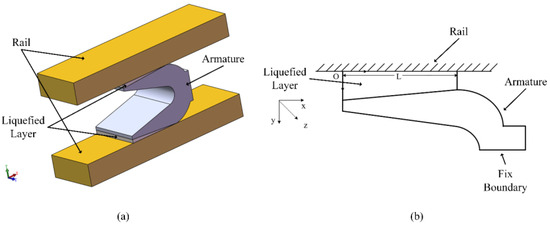
Figure 1.
The schematic diagram of the liquefied layer at the armature–rail contact surface. (a) is a three-dimensional schematic diagram, (b) is a simplified schematic diagram.
2.1. Fluid Dynamics Field
Ignoring the variation in the thickness of liquefied layer in the z-direction, the one-dimensional Reynolds equation between the armature and rails can be expressed as Equation (1), as follows [18]:
where U is the relative velocity between the armature and rails, is the viscosity coefficient, is the density of the liquefied layer, is the melting rate of the surface of the armature, and is the thickness of the liquefied layer.
The boundary conditions of the Reynolds equation are given in Equations (2) and (3), as follows [18]:
where is the atmospheric pressure, L is the length of the armature, is the magnetic pressure, is the magnetic induction in the z-direction, and is magnetic permeability.
2.2. Electromagnetic Field
Assuming that the armature and rails are sufficiently thick in the z-direction, the components of the magnetic flux density in the x and y directions, as well as the current component in the z-direction, can be neglected. By deriving from Maxwell’s equations, the two-dimensional magnetic diffusion model equation is given in Equation (4), as follows [19]:
where t is time and is electrical conductivity.
Assuming the armature is stationary, with the armature as the reference frame, the rail moves backward with a velocity of −U. The calculations for current density in the x-direction and current density in the y-direction are given in Equations (5) and (6), as follows [19]:
The forces exerted on the armature in the x and y directions are described in Equations (7) and (8), as follows [19]:
2.3. Thermal Field
The heat at the armature–rail interface mainly consists of two components: the Joule heating generated by the contact resistance, as given in Equation (9), and the frictional heat generated by the relative motion between the armature and rails, as given in Equation (10):
where is the Joule heating, is the frictional heat, R is the contact resistance, is the friction coefficient, and is the electromagnetic force exerted on the armature in the y-direction.
Thus, the total thermal power at the contact interface is given in Equation (11):
The heat transferred into the interior of the armature from the armature–rail interface is given in Equation (12):
where is the thermal conductivity of the armature, is the thickness of the armature, is the thermal conductivity of the armature–rail interface, an is the thickness of the armature–rail interface.
Assuming that all the heat transferred from the armature–rail interface into the armature is used for melting the armature, the mass of the armature melted per unit of time is given in Equation (13):
where is the mass of the armature melted per unit of time, is the latent heat of the armature, is the specific heat capacity of the armature, is the melting temperature of the armature, and is the initial temperature of the armature.
The melting rate of the surface of the armature is given in Equation (14):
where is the area of the melted region.
2.4. Solid Mechanics Field
The hardness of the rail is higher than that of the armature, and it is well supported, so only the deformation of the armature is considered, while the deformation of the rail is neglected. When a liquefied layer exists at the armature–rail interface, the armature mainly experiences pressure from the liquefied layer and the electromagnetic force induced by the magnetic field. We assume that, under the action of these two forces, the armature deforms, and all the gaps after deformation between the armature and rails are filled by the metal liquefied layer. The armature has a symmetrical structure, as shown in Figure 2, and in the y-direction, it is mainly subjected to electromagnetic force and liquid pressure. In order to reduce computational complexity, the 1/2 model is used in this paper. In practice, both tails of the armature experience equal and opposite electromagnetic forces in the y-direction. The expansion force at the tail of the armature is equal to the combined force of the electromagnetic force acting on the tail of the armature in the y-direction and the internal stress cancelation of the armature structure. Due to the assumption of a fixed armature head in the cantilever beam model, the electromagnetic force counteracted by the internal structure of the armature is ignored, resulting in an overestimation of the calculated thickness of the liquefied layer. This model uses the axis of symmetry of the armature as a fixed boundary to counteract the structural forces acting on the interior of the armature, as shown in Figure 2.
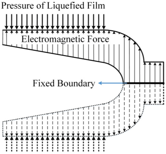
Figure 2.
The symmetrical structure of the armature.
2.5. Model Assumptions
- (1)
- The liquefied layer is an incompressible liquid and is laminar.
- (2)
- Given that the liquefied layer is on the micron scale, the variation in the magnetic field within the liquefied layer in the magnetic diffusion model is neglected.
- (3)
- Due to the hardness and melting point of rails being higher than those of the armature, the deformation and melting of the rail are disregarded.
- (4)
- This paper focuses on calculations under a two-dimensional steady state, ignoring parameter changes in the z-direction.
- (5)
- The pressure and the thickness of the liquefied layer calculated in this paper are the values obtained under steady-state conditions.
2.6. Multiphysics Coupling
The calculation process is mainly divided into two parts: parameter solving and iterative solving. In the parameter solving part, the magnetic diffusion model is used to calculate the current, magnetic field, the velocity of the armature, heat generation between the armature and rails, and the melting rate of the armature. In the iterative solving part, an initial thickness of the liquefied layer is assumed and the parameters calculated in the parameter solving part are substituted into the Reynolds equation to compute the pressure of the liquefied layer (P1). Then, the pressure of the liquefied layer is used in the solid mechanics module to calculate the thickness of the liquefied layer (h1). The two processes are iteratively solved, and convergence is considered to have been achieved when the difference in the thickness of the liquefied layer between two iteration steps is smaller than a predetermined threshold. Parameters of the simulation are presented in Table 1, and the flowchart is shown in Figure 3.

Table 1.
Parameters of the simulation.
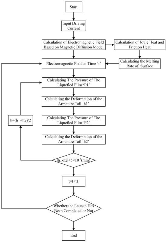
Figure 3.
The flowchart of the simulation.
3. Results and Discussion of Simulation
3.1. Setup of Simulation
In order to investigate the influence of different ripple coefficients on the thickness and pressure of liquefied layer, four driving currents with different ripple coefficients are set in the calculation, as shown in Figure 4. The RC of the ideal trapezoidal waveform is 0%, with a peak value of 250 kA, a rise time of 0.25 ms, and a flat-top stage of 1.25 ms. For the current waveform with small amplitude fluctuations, the RC is 5.7%, with a fluctuation amplitude of 10 kA and a fluctuation period of 0.25 ms. The current waveform with medium amplitude fluctuations has a RC of 8.6%, a fluctuation amplitude of 15 kA, and a fluctuation period of 0.25 ms. For the current waveform with large amplitude fluctuations, the RC is 11.4%, with a fluctuation amplitude of 20 kA and a fluctuation period of 0.25 ms.
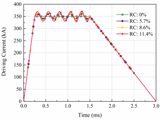
Figure 4.
Driving current in the simulation.
3.2. Velocity of the Armature
The velocity of the armature under four different driving currents is shown in Figure 5. In this calculation, the current ripple is sinusoidal. Therefore, the velocities calculated for the four current waveforms exhibit identical behavior at the rising and falling edges of the current, both reaching 1998 m/s at 2.5 ms. Since the current waveform begins to fluctuate at the flat top stage, the current and magnetic field fluctuate during the launch process, and the velocity of the armature also fluctuates, as shown in the enlarged area in Figure 5. The velocity of the armature changes with the ripple, but the overall variation is relatively small. Because the current fluctuation with an RC of 11.4% is the largest, the fluctuation of the velocity of the armature is also the largest.
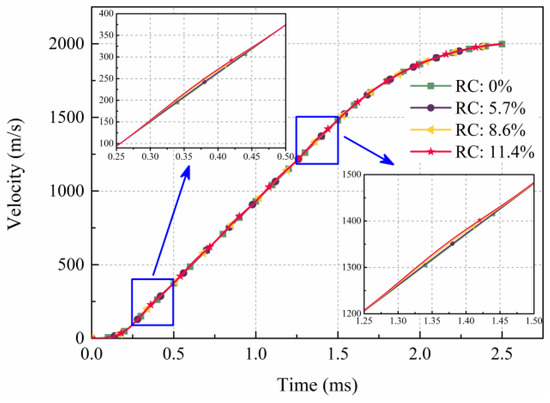
Figure 5.
The velocity of the armature for different current ripples.
3.3. Melting of the Armature
Figure 6 shows the melting rates of the armature of four different current waveforms, which are influenced by both Joule heating and frictional heating. The rising and falling edges of the four current waveforms are consistent, so the melting rates are consistent. The maximum melting rate is 1.4 m/s at 1.5 ms. During the rising edge, the current increases rapidly, and the velocity of the armature and the electromagnetic force acting on the armature tail are relatively small. The heat is mainly generated by Joule heat at the armature–rail interface, and the melting rate rises rapidly. When the RC is 0%, at 0.25 ms, the current reaches the flat top stage, the current is stable, and the generated Joule heat remains constant. The movement of the armature can be regarded as uniformly accelerated motion. The pressure between the armature and the rail remains unchanged, while the frictional heat increases linearly. Therefore, the melting rate of the armature begins to rise linearly. However, after 0.25 ms, the driving currents with RCs of 5.7%, 8.6%, and 11.4% cause the melting rate to fluctuate by affecting the electromagnetic force of the armature tail, Joule heating, and the velocity of the armature. The amplitude of fluctuations in the melting rate increases with increases in the ripple coefficient. Although the current and the velocity fluctuate, the melting rate increases continuously within the range of 0.25–1.5 ms. This is because of the accumulation of the heat on the contact surface of armature and rail.
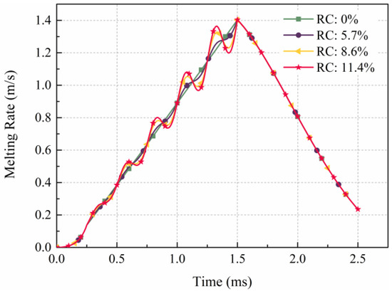
Figure 6.
The melting rate of the armature.
3.4. Thickness of Liqufied Layer
Figure 7 presents the distribution of thickness of the liquefied layer corresponding to four different currents over a time range of 0.1 to 1.5 ms, where x = 0 mm and x = 36 mm corresponding to the armature tail and shoulder, respectively. The maximum thickness of the liquefied layer is greater than 168.1 μm. In this paper, the C-shaped armature structure is used. In this paper, the C-shaped armature is used and the velocity skin effect that results in the current is concentrated in the tail of the armature, which causes the largest electromagnetic force in the tail of the armature. Due to the greater thickness of the armature shoulder and the thinner tail in the y-direction, along with the fixed constraints at the shoulder, the deformation of the armature tail is more significant than that of the shoulder under the combined influence of electromagnetic and liquefied layer pressures. During the rising edge of the current, due to the significant variation in current, the change in Joule heat is also substantial, resulting in a corresponding increase in the thickness of the liquefied layer. In the flat top stage, since the current variation is minimal, the change in Joule heat is also small, leading to negligible changes in the liquefied layer thickness. As shown in Figure 7a, for a current with a RC of 0%, the thickness of the liquefied layer increases over time. This is because the heat is mainly from Joule heat at the rising edge of current. In the flat top stage and falling edge stage, the heat is mainly from Joule heat and friction heat. The thickness of the liquefied layer is positively correlated with the heat; the thickness also fluctuates with current fluctuation, as shown in Figure 7b–d. When the RC is 5.7%, the thickness distribution of the liquefied layer is basically consistent with that with an RC of 0%. However, when x < 8, the thickness of the liquefied layer at 1.3 ms is greater than that at 1.5 ms; this is due to the fact that large fluctuations in the current result in the large fluctuations in Joule heat and friction heat, which directly affect the thickness of the liquefied layer. Thickness curves of a liquefied layer with x = 0 are shown in Figure 8. The amplitude of the fluctuation has a significant impact on the thickness of the liquefied layer. The large fluctuations in the thickness of the liquefied layer may have adverse effects on the contact at the armature–rail interface.
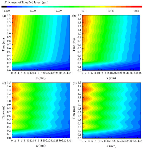
Figure 7.
The distribution of thickness of the liquefied layer. (a) RC: 0% (b) RC: 5.7% (c) RC: 8.6% (d) RC: 11.4%.
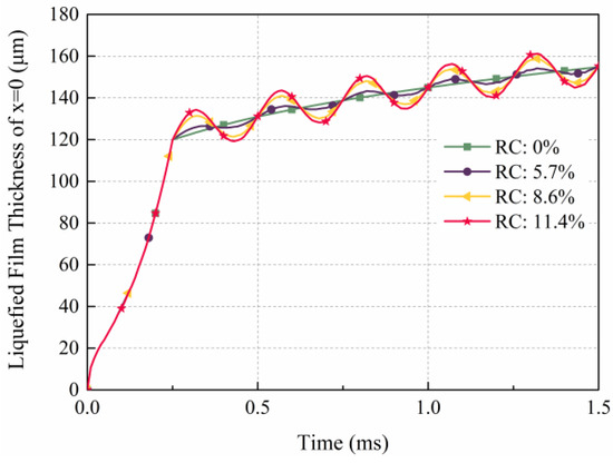
Figure 8.
Thickness curves of liquefied layer with x = 0.
3.5. Pressure of Liqufied Layer
The distribution of pressure in the liquefied layer is shown in Figure 9. Due to Joule heating and frictional heating, the armature reaches the melting point, resulting in the formation of a liquefied layer. The liquefied layer generates pressure at the armature–rail interface. In the current with an RC of 0%, the current remains constant during the flat top stage, so the pressure of the liquefied layer remains unchanged after 0.25 ms at x = 0. Similarly, in the currents with RCs of 5.7%, 8.6%, and 11.4%, the pressure of the liquefied layer is the same at different times due to current fluctuations. The maximum pressure of the liquefied layer, under four currents, is observed at a location approximately 25 mm from the tail of the armature. The maximum pressure of the liquefied layer exceeds 164.9 MPa. Because the armature tail is thin and unconstrained, the deformation is large, and the pressure of the liquefied layer at the armature tail is small. On the contrary, because the armature shoulder is thick and the armature symmetry axis is constrained, the deformation is small, and the pressure of the liquefied layer at the armature shoulder is large. When the RC is 0%, the pressure of the liquefied layer increases with time. In the currents with RCs of 5.7%, 8.6%, and 11.4%, the pressure of the liquefied layer fluctuates with the fluctuation of the current. The greater the ripple coefficient, the greater the pressure of liquefied layer. As shown in Figure 9b–d, for a constant x, the pressure of the liquefied layer initially increases, then decreases, and subsequently increases again over time. This behavior can be attributed to the current fluctuations, which induce variations in the thickness of the liquefied layer, consequently leading to changes in the liquefied layer’s pressure. The instability of the pressure of the liquefied layer leads to the phenomenon of ejection at the armature–rail contact surface, causing instability within the liquefied layer. This instability also affects the lubricating function of the liquefied layer, which reduces the velocity of the armature. Additionally, the pressure instability of the liquefied layer enables the uneven deformation of the armature, resulting in unstable contact resistance. Electrical arcs or even transition between the armature and rails may occur, and the lifetime of the launcher may be reduced.
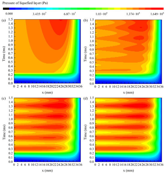
Figure 9.
The distribution of pressure of the liquefied layer: (a) RC: 0%; (b) RC: 5.7%; (c) RC: 8.6%; (d) RC: 11.4%.
By integrating the thickness of the liquefied layer, the volume of the liquefied layer at each time can be obtained. The change in the liquefied layer volume of the four current waveforms with time is consistent with the change in the liquefied layer thickness at the armature tail. By multiplying the melting rate by the area of the armature-rail contact surface and integrating the time, the curve of the total melting amount of the armature with time can be obtained, as shown in Figure 10. The intersection of the two curves represents that the total volume of molten metal on the armature surface is equal to the volume of the liquefied layer at that moment. In other words, without considering the ideal situation that the liquefied layer is deposited on the track and ejected on the insulators, at the intersection of the two curves, the total amount of molten metal melted on the armature surface can reach the volume required for the stable state of the liquefied layer. As illustrated in the figure, the time at which the intersection point occurs advances with an increase in the ripple coefficient, while the corresponding volume decreases. It can be seen from Figure 10 that the time corresponding to the intersection is advanced with the increase in the ripple coefficient, while the corresponding volume decreases. This can be attributed to the current fluctuations, which induce the fluctuation in the liquefied layer at the armature–rail interface and the volume of the liquefied layer. The higher the ripple coefficient, the greater the fluctuation of the liquefied layer’s volume. Consequently, the intersection of the armature melting volume occurs earlier, and the associated volume becomes smaller. During the startup stage of the armature, since the liquefied layer has not yet reached a steady state and the velocity of the armature is relatively low, the liquified layer between the armature and rails is in a very unstable state, leading to the significant ejection of molten metal. Therefore, the actual time at which the liquefied layer between the armature and rails reaches a stable state may occur later than that at the intersection point. As the current fluctuates, the volume of the liquefied layer also fluctuates. At the falling edge of the ripple, the volume required for the liquefied layer to reach a steady state is reduced. However, as molten metal is still melting out of the armature–rail interface, the surplus molten metal either deposits on the rail surface or ejects from the armature–rail interface, which causes the occurrence of arc or even transition at the armature–rail interface.
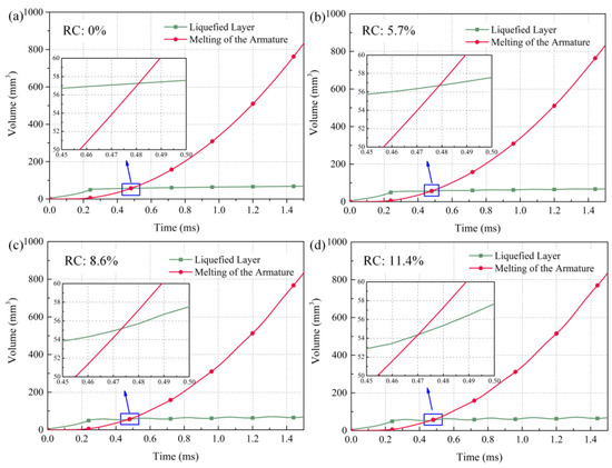
Figure 10.
The total melting amount of the armature: (a) RC: 0%; (b) RC: 5.7%; (c) RC: 8.6%; (d) RC: 11.4%.
4. Experimental, Results and Discussion
4.1. Setup of Experiment
One launch experiment was carried out. The schematic of the electromagnetic launcher system is shown in Figure 11. The launching system consists of a pulsed power supply, hydraulic loading device, busbar, launcher, silencer, and collector. The caliber of the launcher is 14 mm × 16 mm, and the length of the launcher is 1000 mm. Because the rail needs to be connected to the busbar, the length of the rail is 1130 mm. The rail material used in the experiment is chromium–zirconium–copper alloy. The armature used in the experiment is a C-shaped armature made of 6061 aluminum alloy, shown as Figure 11. The driving current, muzzle voltage, and macro morphology of the surface of the rails were measured using a Rogowski coil, a high-voltage differential probe, and a camera.
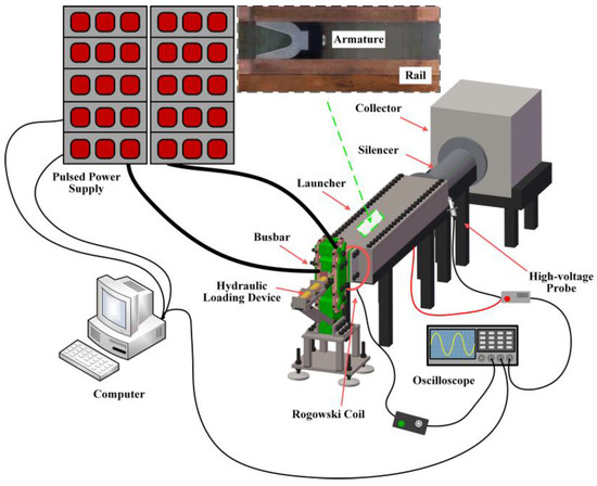
Figure 11.
Schematic of electromagnetic launcher system.
4.2. Discussion and Results of Experiments
The driving current and muzzle voltage are shown in Figure 12. The X axis is the armature displacement and x = 0 is the startup position of the armature. The peak value of the current is 216 kA. There are fluctuations in the current waveform, with a total of six peaks, because the pulse power supply is conducted in six distinct time sequences. The muzzle voltage is represented by the red line in Figure 12. Before the displacement of the armature reaches 400 mm, the muzzle voltage is relatively smooth, indicating that the sliding electrical contact is in good condition. However, when the displacement of the armature is between 400 and 460 mm, as indicated by the blue dashed area in Figure 12, the muzzle voltage increases by approximately 50 V, which indicates that there are some arcs or even transition between the armature and rail at this position. This area corresponds to the falling edge of the current ripple. By observing the rails after the experiment, we found there to be traces of arcs on the surface of the anode rail when the armature displacement is 400–460 mm, as shown in the blue dashed box in Figure 13. Between 120 mm and 400 mm, there are some traces of molten metal ejecting at the edges of the cathode and anode tracks, as shown in the green dashed box in Figure 13. The driving current only fluctuates of armature displacement between 120 mm and 400 mm is significant. Because of the current’s fluctuation, the thickness and pressure of the liquefied layer between the armature and the rail also fluctuate, leading to the deposition of molten metal ejection marks on the rail surface during the startup and low-velocity stages of the armature. During the high-velocity stage, the volume of the liquefied layer decreases, due to the falling edge of the current fluctuation. This is combined with the fluctuations in the thickness and pressure of the liquefied layer between the armature and rail, which results in the degradation of the sliding electrical contact. Consequently, arcs or even transitions may occur between the armature and rail, leading to a reduction in the service life of rails. Experiments and simulations confirm the accuracy of the calculation results.
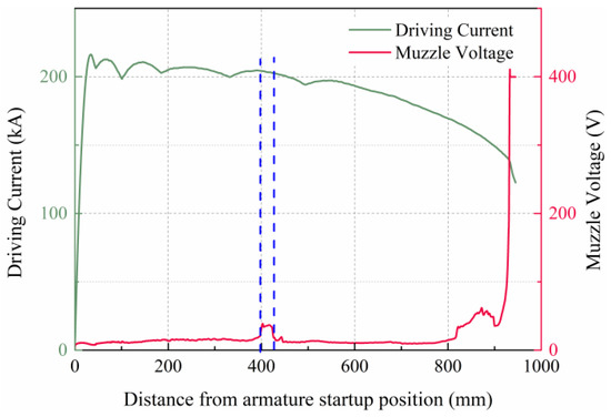
Figure 12.
Driving current and muzzle voltage.
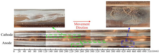
Figure 13.
Macro-morphology of the surfaces of the rails.
5. Conclusions
In this paper, a thermoelastic hydrodynamics model is established by coupling temperature, stress, and an electromagnetic field. The effect of current ripple fluctuation on the thickness and pressure of the liquefied layer and on the melting rate of the armature is analyzed. In addition, a launching experiment is conducted to investigate the effect of the current ripple fluctuation on a sliding electrical contact by analyzing muzzle voltage and traces on the surfaces of the rails. The conclusions are as follows.
- (1)
- The thickness and pressure of the liquefied layer at the armature–rail interface and the melting rate of the armature fluctuate with the fluctuation of the current. As the fluctuation coefficient increases, the amplitudes of fluctuations in both the thickness and pressure of the liquefied layer become more pronounced.
- (2)
- Due to the instability of the thickness and pressure of the liquefied layer, as well as the high velocity of the armature, the sliding electrical contact between the armature and rails deteriorates, and arcs or even transition occurs between the armature and the rails, which reduces the life of the rails.
- (3)
- During the startup and low-velocity stages of the armature, fluctuations in the driving current lead to fluctuations in the melting rate of the armature and the volume of liquefied layer, ultimately resulting in the deposition of the liquified layer at the edges of the rail in the form of ejection.
In this paper, a thermoelastic magnetohydrodynamic model is conducted to study the influence of fluctuations in current on armature–rail contact, without considering the current, pressure, and melting rate in the Z direction, which may affect the accuracy of the calculations. In the future, a three-dimensional thermoelastic magnetohydrodynamic model should be established to study the liquefied layer, which is more in line with actual phenomena.
Author Contributions
Conceptualization, W.T. and G.W.; methodology, W.T., G.W. and W.Y.; software, W.T. and G.W.; validation, W.T., G.W. and Y.Z.; formal analysis, W.T., G.W. and W.Y.; investigation, W.T. and G.W.; resources, W.T. and G.W.; data curation, W.T; writing—original draft preparation, W.T. and G.W.; writing—review and editing, Y.Z., W.Z., W.Y. and P.Y.; visualization, W.Y. and P.Y.; supervision, P.Y.; project administration, W.Z. and Y.Z.; funding acquisition, W.Z. and Y.Z. All authors have read and agreed to the published version of the manuscript.
Funding
This research was funded by the National Natural Science Foundation of China (Grant Nos. 52173089 and 52207178).
Data Availability Statement
The original contributions presented in this study are included in the article. Further inquiries can be directed to the corresponding authors.
Conflicts of Interest
Author Weikang Zhao was employed by the IEIT Systems Co, Ltd. The remaining authors declare that the research was conducted in the absence of any commercial or financial relationships that could be construed as a potential conflict of interest.
References
- Li, J.; Yan, P.; Yuan, W. Electromagnetic gun technology and its development. High Volt. Eng. 2014, 40, 1052–1064. [Google Scholar]
- Ma, W.; Lu, J. Electromagnetic Rail Launch Theory and Technology; Science Press: Washington, DA, USA, 2020; pp. 211–217. [Google Scholar]
- Stefani, F.; Levinson, S.; Satapathy, S.; Parker, J. Electrodynamic transition in solid armature railguns. IEEE Trans. Magn. 2001, 37, 101–105. [Google Scholar] [CrossRef]
- Braunovic, M.; Myshkin, N.K.; Konchits, V.V. Electrical Contacts: Fundamentals, Applications and Technology; Marcel Dekker Inc.: New York, NY, USA, 2006; pp. 163–169. [Google Scholar]
- Persad, C.; Yeoh, A.; Prabhu, G.; White, G.; Eliezer, Z. On the nature of the armature-rail interface: Liquid metal effects. IEEE Trans. Magn. 1997, 33, 140–145. [Google Scholar] [CrossRef]
- Meger, R.A.; Cooper, K.; Jones, H.; Neri, J.; Qadri, S.; Singer, I.L.; Sprague, J.; Wahl, K.J. Analysis of rail surfaces from a multishot railgun. IEEE Trans. Magn. 2005, 41, 211–213. [Google Scholar] [CrossRef]
- Persad, C.; Castro, Z. Railgun tribology: Characterization and control of multishot wear debris. IEEE Trans. Magn. 2007, 43, 173–177. [Google Scholar] [CrossRef]
- Stiffler, A.K. Friction and wear with a fully melting surface. J. Tribol. 1984, 106, 416–419. [Google Scholar] [CrossRef]
- Drobyshevski, É.M.; Kolesnikova, É.N.; Yuferev, V.S. Influence of lubricant on the motion of a body in an electromagnetic railgun accelerator. I. Electric current distribution in the accelerated body and the rails. Tech. Phys. 1999, 44, 831–838. [Google Scholar] [CrossRef]
- Kothmann, R.E.; Stefani, F. A thermal hydraulic model of melt-lubrication in railgun armatures. IEEE Trans. Magn. 2001, 37, 86–91. [Google Scholar] [CrossRef]
- Merrill, R.; Stefani, F. A turbulent melt-lubrication model of surface wear in railgun armatures. IEEE Trans. Magn. 2005, 41, 414–419. [Google Scholar] [CrossRef]
- Ghassemi, M.; Molayi Barsi, Y. Effect of liquid film (indium) on thermal and electromagnetic distribution of an electromagnetic launcher with new armature. IEEE Trans. Magn. 2005, 41, 408–413. [Google Scholar] [CrossRef]
- Thiagarajan, V.; Hsieh, K.-T. A magnetofluid mechanical model to describe rail–armature interface phenomena. IEEE Trans. Magn. 2007, 43, 198–203. [Google Scholar] [CrossRef]
- Yao, J.; Xia, S.; Chen, L.; He, J.; Xiong, Y.; Zhang, C. Analysis of hydrodynamic lubrication considering the self-acceleration of a liquid conducting film at rail–armature interface. IEEE Trans. Plasma Sci. 2019, 47, 2256–2263. [Google Scholar] [CrossRef]
- Xia, S.; Wu, P.; Xiong, Y.; Xu, J.; Ruan, J.; Wang, Z.; Chen, L.; Li, C. Simulation on side-ejecting characteristics of metal liquid film in electromagnetic launcher. IEEE Trans. Plasma Sci. 2020, 48, 4006–4013. [Google Scholar] [CrossRef]
- Liao, G.; Wang, W.; Wei, C.; Zhao, H.; Liu, X. Characterization of magneto-thermo-hydrodynamic lubrication of metal liquid film at armature/rail interface. Tribol. Int. 2023, 189, 108912. [Google Scholar] [CrossRef]
- Liao, G.; Wang, W.; Wang, B.; Chen, Q.; Liu, X. Transient mixed-lubrication and contact behavior analysis of metal liquid film under magneto-thermal effect. Int. J. Mech. Sci. 2024, 271, 109142. [Google Scholar] [CrossRef]
- Li, C.; Xia, S. Study on lubrication characteristics of metal liquid film based on Electromagnetic-Elastic Mechanics-Hydrodynamics Multiphysics coupling model. Materials 2020, 13, 1056. [Google Scholar] [CrossRef] [PubMed]
- Ruan, J.; Chen, L.; Wang, Z.; Li, C.; Wu, P.; Xia, S. Transition mechanism based on load imbalance of liquid metal film. IEEE Trans. Plasma Sci. 2020, 48, 3720–3726. [Google Scholar] [CrossRef]
Disclaimer/Publisher’s Note: The statements, opinions and data contained in all publications are solely those of the individual author(s) and contributor(s) and not of MDPI and/or the editor(s). MDPI and/or the editor(s) disclaim responsibility for any injury to people or property resulting from any ideas, methods, instructions or products referred to in the content. |
© 2025 by the authors. Licensee MDPI, Basel, Switzerland. This article is an open access article distributed under the terms and conditions of the Creative Commons Attribution (CC BY) license (https://creativecommons.org/licenses/by/4.0/).