Abstract
In the field of mining transportation, methanol range-extended powertrain systems are emerging as the preferred solution to address heavy-duty transport challenges in mining areas, leveraging their low-carbon emissions and long-range endurance. However, conventional energy storage technologies face trade-offs between energy density, power density, and cycle life: lithium-ion batteries (Li-ion) have a high energy density but short cycle life, while supercapacitors (SCs) have a high power density and long cycle life but low energy density. To address these limitations, a hybrid energy storage system (HESS) combining Li-ion and supercapacitors (SCs) is proposed as the energy storage unit for the methanol range-extended mining truck (MRMT) in this study. Firstly, the power architecture of MRMT with HESS is designed. Then, the range-extender, Li-ion battery, and SCs are matched and selected based on the operating conditions of the mining truck. Finally, a whole vehicle energy management strategy is developed, and the vehicle power system performance is simulated by combining MATLAB/Simulink (R2022a) with AVL-Cruise (R2019.2). Comparison with conventional single Li-ion range-extender system reveals that the MRMT with HESS reduces methanol consumption by 6.4% and extends the cycle life of Li-ion by 353.4%. This study provides a technological path for the green transformation of mine transportation that is both economical and sustainable.
1. Introduction
The application of a range-extender system in mining trucks can significantly extend mileage and enhance performance. In the context of the global promotion of renewable energy development and efforts to achieve energy transformation [1,2,3,4,5], it has a very considerable promotion prospect [6,7]. With the continuous advancement of methanol engine research, the emission level of the MRMT is expected to be further optimized and improved [8,9]. At the same time, the energy storage form and control method of range-extended mining trucks are undergoing rapid and continuous changes and updates [10,11].
The range-extended powertrain has emerged as a critical direction for commercial vehicle power innovation due to its high thermal-to-electric conversion efficiency and low-carbon emission characteristics [12]. This technological system has not only garnered dual attention from academia and industry but also driven breakthrough progress in key areas such as the optimization of power topology configurations, the coordinated control of multi-source energy consumption, and enhanced adaptability to dynamic operating conditions [13]. Empirical studies indicate that intelligent energy allocation strategies improve mission completion rates for range-extenders in heavy-duty transportation while effectively reducing carbon emissions and operational costs and enhancing power system reliability [14].
Current research primarily focuses on powertrain architecture design and energy management strategies [15,16], yet persisting technical bottlenecks remain. Existing achievements predominantly rely on single energy storage systems or steady-state condition modeling, with insufficient analysis of multi-energy dynamic coupling characteristics in complex mining operation scenarios [17,18]. Theoretical gaps persist in areas such as battery thermal management optimization [19], the dynamic allocation of regenerative braking energy [20], and composite energy storage topology design [21,22]. Specifically, while the multi-scale energy allocation method proposed by Liu’s team [23] enhances system efficiency, its adaptability to dynamic operating conditions remains limited. Han [24] and Lu [25], respectively, employed deep reinforcement learning and model predictive control for energy management optimization, yet neither established a coordinated control framework for hybrid energy storage systems. These limitations indicate that current range-extended mining trucks still have potential for improvement in terms of comprehensive energy utilization efficiency and critical component durability [26,27].
The root cause of these technical barriers lies in inherent contradictions in the performance parameters of traditional energy storage devices: Li-ion batteries offer high energy density advantages but suffer from low power density and limited cycle life, while SCs possess ultrahigh power density and exceptional cycle longevity but are constrained by insufficient energy density [28]. This mutually exclusive performance parameter relationship severely restricts mining vehicles’ operational performance under extreme conditions. Consequently, how to achieve the complementary optimization of multi-energy dynamic characteristics through hybrid energy storage topology innovation has become a crucial research direction for breaking through industry technical barriers [29].
To address the above problems, this paper proposes an energy management strategy for MRMT based on HESS with the following core contributions:
- Focusing on the working characteristics of Li-ion batteries, SCs and range-extenders, this study puts forward the topology of the programmable mining truck based on HESS, analyzes the energy supply mode and energy flow path of the whole vehicle, and provides a theoretical basis for subsequent work.
- Based on the multiple energy sources of this system and the power supply mode of the whole vehicle, the working modes of the whole vehicle are divided into three levels, namely, SOC for Li-ion batteries, SOC for SCs, and vehicle demand power, and the switching rules for each working mode are summarized so as to formulate a three-dimensional energy management method integrating the constant power control strategy and the power-following control strategy, so as to make the energy utilization rate of each component reach its optimal value.
- After completing the selection of the range-extender, in order to further test the relevant performance parameters of the range-extender, this study conducts a complete bench test of the target range-extender to determine the optimal working mode of the range-extender and the relevant core indexes, which provides a data basis for the subsequent simulation experiments.
This study provides a theoretical basis and technical paradigm for the engineering application of heavy-duty supercharged mining trucks through the co-simulation of AVL-Cruise and MATLAB/Simulink and the verification of bench experiments. The research results not only fill the gap of multi-energy co-optimization under complex working conditions in mines but also provide new ideas for the design of dynamic control strategies for HESSs.
2. Power Architecture of MRMT with HESS
The power architecture of the MRMT with an HESS proposed in this paper is shown in Figure 1. It mainly consists of a methanol engine, a generator, a Li-ion battery, an SC, a drive motor, and their respective controllers. The engine is connected to the generator by means of a spline. The engine control unit (ECU) communicates with the engine and the generator control unit (GCU) communicates with the generator with the aid of the CAN bus, the range-extender control unit (RCU), the engine, and the generator. The ECU and GCU together form the auxiliary power unit (APU). The vehicle control unit (VCU) establishes communication with each control unit via the CAN bus. The Li-ion battery and supercapacitor are connected in parallel and together with the battery management system (BMS1 and BMS2), forming the power battery system as the vehicle energy storage unit.
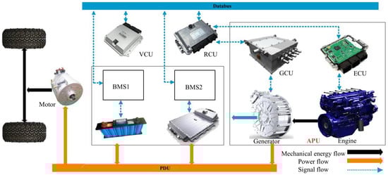
Figure 1.
The power architecture of MRMT with HESS.
The RCU receives control commands from the VCU and provides feedback. The RCU sends start/stop/torque/speed commands to the GCU/ECU and receives status information from the GCU/ECU to realize the closed-loop control of the GCU and ECU. The energy flow is controlled by the RCU and power distribution unit (PDU) based on the status of the vehicle, the power battery, the engine, and the generator. The composition of multiple energy sources allows the vehicle to call the energy supply unit with the best performance under the current working conditions in real time during driving, which further reduces energy waste.
There are three energy flow paths in the proposed power system, as shown in Figure 2.
- Path (I): Engine → Generator → Li-ion → Drive motor;
- Path (II): Engine → Generator → SC → Drive motor;
- Path (III): Engine → Generator → Drive motor.
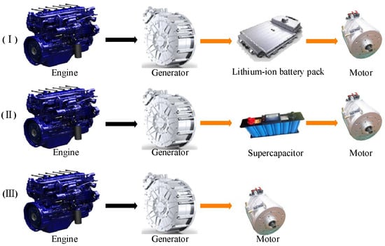
Figure 2.
Schematic diagram of the energy transmission path of MRMT with HESS.
That is, it is divided into three power supply methods: the Li-ion power supply, the supercapacitor power supply, and the range-extender direct power supply. Firstly, the SC has a high power density, an extremely long charging and discharging cycle life, etc. It is set as the most prioritized power supply unit, so that it is frequently charging and discharging in order to share the pressure of the Li-ion battery’s energy supply. Secondly, although the power density of the Li-ion battery is not as high as that of the supercapacitor, it has an energy density far exceeding the former and has zero emission and pollution-free characteristics, so it is treated as the core energy storage device for this system. Finally, the APU acts as a power assist unit, converting the internal energy of the fuel into electrical energy through combustion, thus supplying power to the power battery system or directly driving the vehicle.
3. Working Modes and Control Strategy of MRMT
3.1. Working Modes of MRMT
There are seven operating modes in the MRMT with HESS proposed in this paper, and their judgment is based on the SOC for SCs, SOC for Li-ion batteries, and the power demanded by the whole vehicle together. As illustrated in Figure 3, the system first categorizes the supercapacitor’s SOC into predefined intervals (Event 1, Event 2, and Event 3) based on preliminary thresholds, as shown in Figure 3a. Subsequently, the current operating state is refined according to the SOC of the Li-ion battery and the power demand level, as detailed in Figure 3b–d:
- (1)
- When the SC power is sufficient and the Li-ion battery does not need to be charged, only the SC supplies power to the drive motor, and the whole vehicle is in mode 1;
- (2)
- When the SC power is sufficient but the Li-ion battery is in a low potential state, only the SC supplies power to the drive motor, the APU turns on to supply power to the Li-ion battery, and the whole vehicle is in mode 2;
- (3)
- When the Li-ion battery has enough power, the SC is in a low power state, and the power demand of the whole vehicle is less than Pe_low, the Li-ion supplies power to the drive motor alone, the APU starts to supply power to the SC, and the whole vehicle is in mode 3;
- (4)
- When the supercapacitor and Li-ion battery are in a low power state and the demand power of the whole vehicle is less than Pe_low, the APU will be turned on to charge the Li-ion battery and SC while supplying power to the drive motor, and the whole vehicle is in mode 4;
- (5)
- When the SC and Li-ion battery are in a low power state and the power demand of the whole vehicle is greater than Pe_hi, the APU supplies power to the drive motor only, and the whole vehicle is in mode 5;
- (6)
- When the Li-ion power is sufficient, the SC is in a low power state, the power demand of the vehicle is greater than Pe_hi, and the Li-ion drive alone cannot meet the needs of the vehicle, the Li-ion and the APU jointly supply power to the drive motor; that is, the whole vehicle is in mode 6;
- (7)
- When the Li-ion power is sufficient, the supercapacitor is in a low power state, and the vehicle demand power is located between Pe_low and Pe_hi, the Li-ion and the APU co-supply power to the drive motor. Meanwhile, the APU also supplies power to the supercapacitor. In this case, the SOC range is set as = 20% and = 80%, which indicates mode 7.
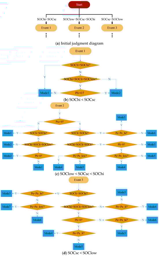
Figure 3.
Vehicle status determination rule chart.
In the proposed energy management strategy, the charging power from the APU to the Li-ion and SC is equal to the rated working power of the Li-ion and SC, respectively. The supplied power from the APU to the drive motors is equal to the rated power of the motor when the APU directly drives. The following is the power relationship of devices in each working mode:
Mode 1:
Mode 2:
Mode 3:
Mode 4:
Mode 5:
Mode 6:
Mode 7:
3.2. Control Strategy of MRMT
When the vehicle is in operation, the vehicle recognizes the current working condition and transmits signals to the system described herein, and each component works according to a predetermined strategy, as shown in Figure 4. For example, when the vehicle is under a high power demand, that is, = 20%, = 80%, , and the SC and Li-ion battery are in a high power stage, that is, = 20%, = 80%, , , the vehicle operating mode enters the scheme shown in Figure 4c. The SC supplies power to the drive motor alone (Mode 1) until the SC power drops to the medium-power stage, and the vehicle operating mode enters that shown in Figure 4b. In this mode, the SC continues to supply power to the drive motor alone (Mode 1). Since the SC drops from the high-power stage to the medium-power stage, the APU operating state judgment result (Mode 1 or Mode 3) in this stage is that the APU does not charge the SC. This strategy can prevent engine fatigue caused by frequent starting and stopping. Then, the SC continues to work until it falls to the low battery stage, and then the vehicle operating mode enters the mode shown in Figure 4a. The SC no longer supplies power to the vehicle, the APU starts to supply power to the SC, and the Li-ion battery starts to drive the vehicle (Mode 3). When the SC is charged to the medium-power stage, that is, = 20% and = 80%, as shown in Figure 4b, the APU working state is judged again (Mode 1 or Mode 3) and the APU continues to supply power to the SC until its power reaches the high-power stage.
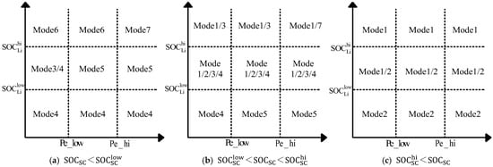
Figure 4.
Energy control strategy of MRMT with HESS.
4. Power Parameter Matching of MRMT with HESS
4.1. Power Matching of Range-Extender
According to the basic parameters and design objectives of the 18-ton MRMT with an HESS, the main parameters of the APU are determined through the allocation of the maximum total power of the whole vehicle; the vehicle’s energy requirements come from either the APU or the power battery system. The total power provided by the co-drive of the APU and power battery and the separate drive of the supercapacitor depends on the maximum speed, climbing ability, and acceleration performance of the MRMT. The maximum power of the APU depends on the maximum speed of the APU in the standalone drive mode, and the peak power of the power battery depends on the maximum speed of the vehicle in the pure electric mode. The power parameters of the APU and battery system are matched from five points of view: the maximum speed, climbing performance, acceleration performance, the maximum speed of the APU in the single drive mode, and the maximum speed in the pure electric mode.
The maximum total power is determined according to the maximum speed of the hybrid drive as follows:
where is the maximum total power of the whole vehicle determined according to the maximum speed of the vehicle in hybrid drive (kW); is the maximum speed in the hybrid drive of the MRMT (km/h); is the total vehicle mass (kg); is the drive train efficiency; is the coefficient of rolling resistance of the tire; is the coefficient of air resistance; and is the windward area (m2).
According to the maximum climbing degree of the hybrid drive of the MRMT, the maximum power of the vehicle is determined as follows:
where is the maximum power of the whole vehicle based on the maximum climbing degree of the hybrid drive of the MRMT (kW); is the maximum climbing angle (deg); and is the speed corresponding to the maximum climbing gradient (km/h).
According to the acceleration performance of the MRMT, the maximum power of the vehicle is determined as follows:
where is the maximum total power of the vehicle determined from the acceleration performance of the MRMT (kW); is the rotating mass conversion factor; is the driving speed (km/h); and is the acceleration (m/s2).
The maximum power of the MRMT yields the following:
The maximum battery power is determined according to the maximum speed of the battery drive mode as follows:
where is the maximum battery system power determined according to the maximum speed of the battery drive mode of the MRMT (kW) and is the maximum speed of the battery drive mode (km/h).
The maximum power of the range-extender is determined according to the maximum speed of the range-extender drive mode as follows:
where is the maximum engine power determined from the maximum speed of the APU drive mode (kW) and is the maximum speed of the APU drive mode of the MRMT (km/h).
4.2. Capacity Matching of Energy Storage System
The total energy of the power battery needs to be determined according to the mileage in the pure electric mode:
where is the total energy of the energy storage system (kWh); is the average vehicle speed (km/h); is the range of the MRMT at a speed of (km); is the high energy point of the power cell; and is the low energy point of the power cell. To avoid deep charging and discharging of the battery and prolong its service life, the SOC (state of charge) of this power battery pack is controlled to range from 0.2 to 0.8; that is, = 20% and = 80%. The internal resistance of the power cell is minimized under this interval and the energy efficiency is the highest.
The supercapacitor power needs to be determined according to the maximum power of the vehicle:
where is the rated power of the supercapacitor, and is the charge–discharge rate.
Table 1 shows the matching and selection results:

Table 1.
Vehicle and core component parameters.
5. Performance Test of Methanol Range-Extender
According to the matching results, the rated power of the range-extender should be no lower than 150 kW. A 7 L methanol engine and a permanent magnet synchronous motor were selected, and the two were mechanically connected to form a methanol range-extender with a rated power of 150 kW.
The methanol range-extender bench experiment is shown in Figure 5. The core part consists of a 7 L methanol engine, a generator, an ECU, a GCU, an RCU, a power analyzer, and a battery simulator. The methanol engine and the generator make up the methanol range-extender. The three-phase AC power from the range-extender is collected by the power analyzer and then continues to be transmitted to the GCU, rectified and transformed by the GCU, and then collected by the pathway power analyzer, and then the processed DC power is transmitted to the battery simulator and finally fed back to the grid by an inverter. During the experiment, the upper computer of the test stand acts as the VCU and sends power requests, the control mode, and control commands to the RCU, which splits the received power request into speed request and torque request and sends them to the GCU and ECU, respectively. The torque is controlled by the ECU, and the speed is controlled by the GCU.
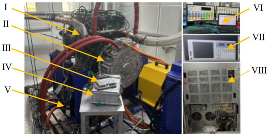
Figure 5.
Methanol range-extender test stand; I—7 L, methanol engine; II, electricity generator; III, RCU; IV, GCU; V, ECU; VI, user interface; VII, power analyzer; VIII, battery simulator.
The bench experiment test should be carried out to meet the requirements of all the working conditions of the range-extender as much as possible. The test speed ranges from 800 rpm to 1700 rpm with an interval of 25 rpm, and the torque takes each 25 Nm as a gradient to reach the external characteristics of the given speed value. After the experiment is completed, the following data can be obtained: Figure 6a shows the maximum power generation of the methanol range-extender at each speed, as well as the power when it has the lowest fuel consumption rate (FCR) and the highest power generation efficiency at each speed, that is, the external characteristic curve and the optimal operating curve. The subsequent experimental data are all based on the optimal working curve of the range-extender as the actual working point. The FCR of this methanol range-extender under each working condition is shown in Figure 6b, and the lowest FCR is 480.2 g/kWh when the power generation is 130 kW. Figure 7 is a map of the universal performance characteristics of the engine, from which it can be seen that the engine has the best fuel economy at a speed of 1200–1800 rpm and an output torque of 650–900 Nm. Figure 8 is a map of the universal performance characteristics of the methanol range-extender, from which it can be seen that the methanol range-extender also has the best fuel economy at a speed of 1200–1800 rpm and an output torque of 650–900 Nm.
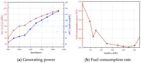
Figure 6.
Methanol range-extender test data.
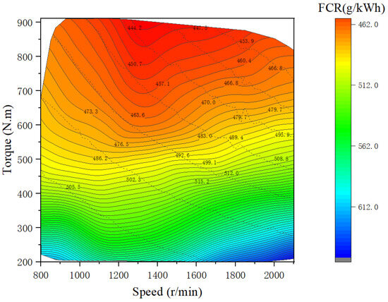
Figure 7.
The map of the methanol engine.
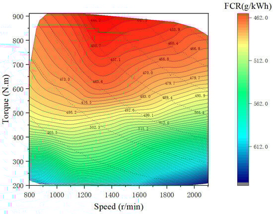
Figure 8.
The map of the methanol range-extender.
6. Simulation of Dynamic and Economic Performance
The vehicle simulation model is built in AVL-Cruise software. The model consists of powertrain, transmission, chassis, and body systems, and the corresponding parameters are set according to the matching power and test data. In the MRMT model, a Li-ion battery and SC are selected as energy storage devices. Key operational parameters include a gross vehicle mass of 18 tons under full load conditions and a standardized DC bus voltage of 540 V. In addition, in this model, due to the existence of a variety of energy flow paths, but also the need to join the DC/DC module to act as a switch for each branch, the software strategy is used to control its switching on and off. Also, considering the complexity of the control strategy, the kinetic energy recovery part is not involved in this model. Mechanical and electrical links are established, and the signal network is set up. The energy management strategy model is built in MATLAB/Simulink, and the co-simulation is performed with AVL-Cruise software by the input/output interfaces. The co-simulation model is shown in Figure 9.
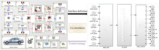
Figure 9.
Schematic of co-simulation.
The co-simulation results of AVL-Cruise and MATLAB/Simulink are shown in Figure 10. Figure 10a shows the target speed and the actual speed of the MRMT with the HESS model built in this paper under 20 CHTC cycles. The two curves completely overlap, which verifies the reliability of this algorithm. Figure 10b shows the operating mode in which the MRMT with an HESS is in actual operation. Figure 10c shows the cycle of the Li-ion battery and SC under 20 CHTC cycles, and the results show that for every charge/discharge cycle of the Li-ion battery, on average, the SC charge/discharge cycle is carried out 58 times. The frequent charging and discharging of the SC effectively alleviate the working pressure of the Li-ion battery. Figure 10d shows the comparison of energy consumption between the Li-ion battery and SC. The total energy consumption of the Li-ion battery under the whole-cycle condition is 136,841 kJ, and the SC consumes 64,450.9 kJ. The energy consumption ratio is about 2.1:1. Figure 10e,f show the actual mechanical power and generation power of the engine and generator, respectively, during 20 cycles.
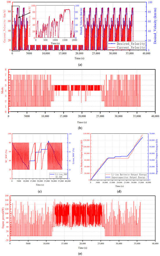
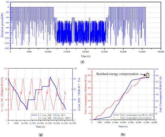
Figure 10.
Dynamic and economic simulation results. (a) Comparison of theoretical and actual speeds. (b) Working modes. (c) SC-Li-ion Charge/Discharge Cycle Comparison. (d) Comparison of energy output between Li-ion and SC. (e) Mechanical power of methanol engine. (f) Range-extender power generation. (g) Li-ion charge/discharge comparison. (h) Methanol Consumption Comparison.
In order to compare our model with a traditional MRMT, the SC is removed, and the power-following control scheme is applied to the whole vehicle to carry out a co-simulation again. Figure 10g shows the SOC comparison of the Li-ion battery with and without an SC. After 20 CHTC cycles, the Li-ion battery undergoes 6.71 charge/discharge cycles in the traditional MRMT and 1.48 cycles in our MRMT with an HESS. A methanol consumption comparison is shown in Figure 10h: under cyclic conditions, the vehicle consumes 301.5 L of methanol in total when a single Li-ion battery is used as the energy storage device, and the 100 km fuel consumption is about 73.4 L. The vehicle consumes 268 L of methanol in total after adopting the HESS, and the 100 km fuel consumption is about 65.51 L. Considering the difference between the initial and final energy storage values, the total fuel consumption is reduced by 6.4% for the MRMT with an HESS.
7. Conclusions
In this paper, the methanol range-extender is selected as the main energy source of a mining truck according to the working condition and performance requirements. The HESS is designed as the energy storage unit, the parameters of the whole vehicle power system are matched, and the energy management strategy is proposed. The dynamic and economic performance of the MRMT with an HESS is co-simulated with AVL-Cruise and MATLAB/Simulink software, and the results are compared with a traditional MRMT, revealing its practical application potential in advancing the green transformation of mine transportation. The main findings and practical implications are summarized as follows:
- (1)
- The integration of an SC significantly alleviated the power stress on the Li-ion battery. Over 20 CHTC cycles, the energy consumption ratio of the Li-ion battery to the SC reaches 2.1:1, with the SC completing 58 cycles for every single charge–discharge cycle of the Li-ion battery. Compared with conventional lithium-only configurations, the Li-ion cycle count decreased from 6.71 to 1.48 cycles and achieved a 353.4% increase in its theoretical lifespan. These advancements provide mining enterprises with an energy solution that balances economic viability with sustainability.
- (2)
- By integrating an HESS that combines a Li-ion battery with an SC, the MRMT achieves marked improvements in energy utilization efficiency. Testing over 20 CHTC cycles demonstrates a 6.4% reduction in methanol consumption compared to a conventional MRMT, with fuel consumption optimized to 65.51 L per 100 km. This innovation has proven to be suitable for high-intensity haulage operations in mining environments, enabling enterprises to reduce fuel expenditures while maintaining the level of operational throughput that characterizes modern mine logistics.
- (3)
- The energy management framework and hybrid energy storage topology design proposed in this study are generic and can be extended to other heavy-duty transportation vehicles or renewable energy storage systems that require dynamic power regulation.
To alleviate the power supply pressure on energy storage units and prolong the service life of hardware components in range-extended mining trucks, this paper proposes a power topology for the vehicle based on an HESS. However, due to time constraints, several unresolved deficiencies remain in the current study, which should be addressed in follow-up research:
- (1)
- In the matching design of the range-extender, the high efficiency interval between the methanol engine and the generator is not well matched, which affects the overall efficiency of the system, and the matching problem between the engine and the generator will be further developed.
- (2)
- In terms of hardware testing, due to the limitations of the experimental conditions of this paper, considering only a methanol range-extender for a complete data test and not analyzing the lithium battery + supercapacitor hybrid energy storage system experiments, the follow-up will be the complete performance analysis of various modules to ensure the feasibility of parameter matching.
- (3)
- The current hardware design and energy management strategy excluded the regenerative braking module due to the complexity of control strategies and hardware integration. Subsequent research will incorporate regenerative braking into the vehicle’s energy management framework to further enhance energy utilization efficiency.
- (4)
- The findings presented in this paper are derived from co-simulation results using AVL-Cruise and MATLAB/Simulink. However, many real-world influencing factors were not fully considered. Future work will validate the proposed strategy through physical vehicle testing when experimental resources become available, thereby enhancing the reliability of this research.
Author Contributions
Y.R.: conceptualization, investigation, methodology, validation, supervision, writing—review and editing. Y.L.: conceptualization, methodology, experiment, investigation, software, validation, writing—original draft. W.L.: investigation, methodology, project administration, resources, software. J.Q.: investigation, methodology, project administration. All authors have read and agreed to the published version of the manuscript.
Funding
This research was funded by the Taiyuan University of Science and Technology High-Level Talent Introduction Research Funding (Grant No. 20242083) awarded to Yong Shu, and the Taiyuan University of Science and Technology Talent Introduction Research Funding (Grant No. 20222114) awarded to Qisheng Zhang. The APC was funded by the aforementioned grants.
Data Availability Statement
Data will be made available on request.
Acknowledgments
This work was financially supported by the Shanxi Engineering Research Center of Internal Combustion Engine Power Technology and the Advanced Technology Innovation Center of Zero Carbon Power Special Vehicle.
Conflicts of Interest
The authors declare that they have no known competing financial interests or personal relationships that could have appeared to influence the work reported in this paper.
Abbreviations
| HESS | Hybrid energy storage system |
| MRMT | Methanol range-extended mining truck |
| Li-ion | Lithium battery |
| SC | Supercapacitor |
| ECU | Engine control unit |
| RCU | Range-extender control unit |
| VCU | Vehicle control unit |
| APU | Auxiliary power unit |
| PDU | Power distribution unit |
| CHTC | China heavy-duty commercial vehicle test cycle |
| SOC | State of charge |
| SOCli | State of charge for Li-ion |
| SOCSC | State of charge for SC |
| GenPwr | Generation power |
| FCR | Fuel consumption rate |
References
- Wang, B.; Yu, X.; Xu, H.; Wu, Q.; Wang, L.; Huang, R.; Li, Z.; Zhou, Q. Scenario analysis, management, and optimization of a new vehicle-to-micro-grid (V2μG) network based on off-grid renewable building energy systems. Appl. Energy 2022, 99, 119873. [Google Scholar] [CrossRef]
- Liang, X.; Wang, P.; Cao, X.; Wan, X.; Chao, P.; Zhao, X.; Yu, A.; Liu, C.; Li, J. Research on improving the safety of new energy vehicles exploits vehicle operating data. Saf. Sci. 2024, 181, 106681. [Google Scholar] [CrossRef]
- Yang, H.; Yang, Z.; Liu, S.; Zhang, D.; Yu, Y. Optimization dispatching strategy for an energy storage system considering its unused capacity sharing. Glob. Energy Interconnect. 2024, 7, 590–602. [Google Scholar] [CrossRef]
- Song, Y.; Xu, L.; Li, J.; Taherian, H.; Zhang, Y.; Liu, D.; Li, Z.; Hou, G. Multi-objective optimization and long-term performance evaluation of a hybrid solar-hydrogen energy system with retired electric vehicle batteries for off-grid power and heat supply. Int. J. Hydrogen Energy 2024, 6, 867–882. [Google Scholar] [CrossRef]
- Yahia, M.; Hicham, B.S.; Fatima, E.; Es-Sbai, N. A soft actor-critic reinforcement learning framework for optimal energy management in electric vehicles with hybrid storage. J. Energy Storage 2024, 99 Pt B, 113344. [Google Scholar] [CrossRef]
- Wang, Y.J.; Tian, J.Q.; Sun, Z.D.; Wang, L.; Xu, R.L.; Li, M.C.; Chen, Z.H. A comprehensive review of battery modeling and state estimation approaches for advanced battery management systems. Renew. Sust. 2020, 131, 10015. [Google Scholar] [CrossRef]
- Wei, Z.B.; Li, P.F.; Cao, W.K.; Chen, H.S.; Wang, W.; Yu, Y.F.; He, H.W. Machine learning-based hybrid thermal modeling and diagnostic for lithium-ion battery enabled by embedded sensing. Appl. Therm. Eng. 2022, 216, 119059. [Google Scholar] [CrossRef]
- Xu, Z.; Wang, J.; Zhao, P.; Jia, M.; Chang, Y.; Du, L. Exploring energy utilization of the methanol/dimethyl ether dual-fuel engine under the methanol reforming strategy: A comparison of different low-temperature combustion modes. Energy 2024, 312, 133659. [Google Scholar] [CrossRef]
- Yin, X.; Yan, Y.; Ren, X.; Yu, L.; Duan, H.; Hu, E.; Zeng, K. Effects of methanol energy substitution ratio and diesel injection timing on a methanol/diesel dual-fuel direct injection engine. Fuel 2024, 382 Pt B, 133773. [Google Scholar] [CrossRef]
- AlKawak, O.A.; Kumar, J.R.; Daniel, S.S.; Reddy, C.V. Hybrid method based energy management of electric vehicles using battery-super capacitor energy storage. J. Energy Storage 2024, 77, 109835. [Google Scholar] [CrossRef]
- Yang, Y.; Xu, Y.; Zhang, H.; Yang, F.; Ren, J.; Wang, X.; Jin, P.; Huang, D. Research on the energy management strategy of extended range electric vehicles based on a hybrid energy storage system. Energy Rep. 2022, 8, 6602–6623. [Google Scholar] [CrossRef]
- Zander, L.; Svens, P.; Svärd, H.; Dahlander, P. Evaluation of a Back-up Range-extender and Other Heavy-Duty BEV-Supporting Systems. World Electr. Veh. J. 2022, 13, 102. [Google Scholar] [CrossRef]
- Wu, X.; Hu, X.; Yin, X.; Peng, Y.; Volker, P. Convex programming improved online power management in a range extended fuel cell electric truck. J. Power Sources 2022, 476, 228642. [Google Scholar] [CrossRef]
- Shiledar, A.; Villani, M.; Rizzoni, G. Hardware-in-the-Loop Implementation of an Optimized Energy Management Strategy for Range-Extended Electric Trucks. Energies 2024, 17, 5294. [Google Scholar] [CrossRef]
- He, L.; Gu, Z.; Zhang, Y.; Jing, H.; Li, P. Study on a novel thermal management system and heat recovery strategy of range extend electric vehicle. Renew. Energy 2024, 237 Pt A, 121538. [Google Scholar] [CrossRef]
- Liu, H.; Lei, Y.; Sun, W.; Chang, C.; Jiang, W.; Liu, Y.; Hu, J. Research on approximate optimal energy management and multi-objective optimization of connected automated range-extended electric vehicle. Energy 2024, 306, 132368. [Google Scholar] [CrossRef]
- Villani, M.; Shiledar, A.; D’Arpino, M.; Rizzoni, G. Battery Selection and Optimal Energy Management for a Range-Extended Electric Delivery Truck. SAE Tech. Pap. 2022, 5, 1282–1291. [Google Scholar] [CrossRef]
- Anil, V.S.; Zhao, T.; Zhao, M.; Villani, M.; Ahmed, Q.; Rizzoni, G. Powertrain design optimization for a range-extended electric pickup and delivery truck. SAE Int. J. Commer. Veh. 2020, 13, 189–203. [Google Scholar] [CrossRef]
- Arasu, M.; Ahmed, Q.; Rizzoni, G. Optimizing Battery Cooling System for a Range Extended Electric Truck; SAE Technical Paper No. 2019-01-0158; SAE International: Warrendale, PA, USA, 2019. [Google Scholar] [CrossRef]
- Koray, E.; Engin, Ö. Prototype production and comparative analysis of high-speed flywheel energy storage systems during regenerative braking in hybrid and electric vehicles. J. Energy Storage 2021, 43, 103237. [Google Scholar] [CrossRef]
- Nguyen-Minh, T.; Nguyễn, B.H.; Vo-Duy, T.; Ta, M.C.; Trovão, J.P.; Antunes, C.H. A universal optimal sizing for hybrid energy storage system of electric vehicles. J. Energy Storage 2024, 92, 112128. [Google Scholar] [CrossRef]
- Yu, X. The Effect of Ultracapacitor on the Performance of Series Range-Extended Hybrid Commercial Vehicle. SAE Int. J. Commer. Veh. 2024, 17, 287–301. [Google Scholar] [CrossRef]
- Liu, H.; Lei, Y.; Fu, Y.; Li, X. A novel hybrid-point-line energy management strategy based on multi-objective optimization for range-extended electric vehicle. Energy 2022, 247, 123357. [Google Scholar] [CrossRef]
- Han, L.; Zhou, X.; Yang, N.; Liu, H.; Xiang, C. Hierarchical energy management for extended-range electric vehicles considering range-extender dynamic coordination. J. Power Sources 2024, 476, 235349. [Google Scholar] [CrossRef]
- Lu, L.; Zhao, H.; Xu, F.; Luo, Y.; Chen, J.; Ding, X. GA-LSTM speed prediction-based DDQN energy management for extended-range vehicles. Energy AI 2024, 17, 100367. [Google Scholar] [CrossRef]
- Ahmadi, S.; Bathaee, S.M.; Hosseinpour, A.H. A review on recent advances on improving fuel economy and performance of a fuel cell hybrid electric vehicle. Int. J. Hydrogen Energy 2024, 89, 22–47. [Google Scholar] [CrossRef]
- Ullah, S.; Hayat, R.; Zeb, K.; Rasheed, A.; Muyeen, S.M. Super-twisting sliding mode controller for energy storage system of a novel multisource hybrid electric vehicle: Simulation and hardware validation. Int. J. Hydrogen Energy 2024, 71, 952–963. [Google Scholar] [CrossRef]
- Yang, K.; Zhang, B.; Chu, Y.; Wang, Z.; Shao, C.; Ma, C. Research on the configuration design and energy management of a novel plug-in hybrid electric vehicle based on the double-rotor motor and hybrid energy storage system. Energy 2024, 302, 131854. [Google Scholar] [CrossRef]
- Maciej, W.; Sebastian, W.; Joanna, W.; Rafał, P. Hybrid battery energy storage for light electric vehicle—From lab to real life operation tests. J. Energy Storage 2024, 81, 110545. [Google Scholar] [CrossRef]
Disclaimer/Publisher’s Note: The statements, opinions and data contained in all publications are solely those of the individual author(s) and contributor(s) and not of MDPI and/or the editor(s). MDPI and/or the editor(s) disclaim responsibility for any injury to people or property resulting from any ideas, methods, instructions or products referred to in the content. |
© 2025 by the authors. Licensee MDPI, Basel, Switzerland. This article is an open access article distributed under the terms and conditions of the Creative Commons Attribution (CC BY) license (https://creativecommons.org/licenses/by/4.0/).