Review

Review of the Diffusion Process, Explosion Mechanism, and Detection Technology of Hydrogen and Ammonia

1
School of Safety Science and Engineering (School of Emergency Management), Nanjing University of Science and Technology, Nanjing 210094, China
2
Graduate School of Technology Management, Kyung Hee University, Yongin-si 17104, Gyeonggi-do, Republic of Korea
*
Author to whom correspondence should be addressed.
Energies 2025, 18(10), 2526; https://doi.org/10.3390/en18102526
Submission received: 25 January 2025 / Revised: 9 March 2025 / Accepted: 14 March 2025 / Published: 14 May 2025
(This article belongs to the Special Issue Green Hydrogen Energy Production)

Abstract

:
Increasing the proportion of clean energy within the energy structure is a crucial strategy for achieving energy transformation. Hydrogen and ammonia, as leaders in clean energy technologies, have garnered significant global attention. The combination of hydrogen and ammonia has emerged as a novel form of energy storage, transportation, and conversion; however, the safety aspects of their application process warrant closer attention. Research on hydrogen safety has been conducted extensively, with particular focus on the leakage, diffusion, combustion, and explosion processes. Both theoretical research and engineering applications have advanced significantly. In particular, hydrogen detection technology, primarily based on electrical measurement, has matured considerably, while schlieren imaging-based flow field visualization technology is progressing steadily. In contrast, safety research concerning ammonia remains in its early stages. Research on the leakage and diffusion characteristics of ammonia predominantly focuses on liquid ammonia, with a strong emphasis on engineering applications. Studies on the combustion and explosion characteristics of ammonia primarily address flame parameters and the combustion development laws. Ammonia serves as an efficient hydrogen storage medium. The conversion process involving hydrogen and ammonia will occur simultaneously in both time and space. Current research has not adequately addressed the safety concerns associated with the application process of hydrogen–ammonia mixtures. Future research on the safety of hydrogen–ammonia application processes should focus on the diffusion characteristics and combustion and explosion behaviors, as well as the development of electrical measurement detection technologies and optical flow field visualization techniques for hydrogen–ammonia mixtures.

1. Introduction

The traditional energy structure is a hierarchical pyramid, predominantly fueled by fossil energy. Given the societal advancements and shifts in supply dynamics, the restructuring of the energy sector is essential to ensure efficient, clean, and orderly development [1,2,3,4,5,6,7,8,9]. Hydrogen energy is a promising emerging energy source in the 21st century [10,11,12,13]. It possesses the characteristics of high energy density, environmentally friendly byproducts, and abundant sources. Hydrogen energy can participate in energy conversion through two primary methods. One method involves converting hydrogen energy into electrical energy via a fuel cell, which is then utilized. This conversion method is considered more moderate [14], and the other approach involves utilizing an internal combustion engine for energy conversion, which serves as a crucial pathway towards achieving decarbonization goals [15]. Currently, numerous countries have implemented hydrogen energy as a novel form of energy supply. China has developed policies aimed at fostering the hydrogen energy automobile industry, thereby significantly promoting the widespread adoption of hydrogen fuel cell vehicles [16]. Early research efforts on hydrogen fuel cell vehicles in South Korea have been extensive. Hyundai was the first to launch a mass-produced fuel cell SUV vehicle globally [17]. India has consistently conducted research on hydrogen production and storage technologies [18], the Japanese government has implemented various fiscal incentives for clean-fuel vehicles to promote their transition to environmentally friendly transportation [19], and Denmark has invested in developing hydrogen-powered cars to achieve its target of a fossil fuel-free transportation sector by 2050 [20]. Additionally, hydrogen-powered ships are increasingly gaining visibility among the public. The world’s first mass-produced hydrogen fuel cell yacht, ‘Energy Observer’, as shown in Figure 1, has footprints all over the world, and Norway, China, and Germany are actively involved in the development of hydrogen-powered ships.
Safe and effective storage and transportation of hydrogen are crucial for its widespread use as an energy form. Currently, there are four primary methods of hydrogen storage: high-pressure gaseous hydrogen storage, low-temperature liquid hydrogen storage, solid-state storage, and chemical hydrogen storage, as shown in Figure 2 [21,22]. High-pressure gaseous hydrogen storage involves compressing the gas to achieve the purpose of storing hydrogen. The hydrogen remains in a gaseous state during this process. Cryogenic liquid hydrogen storage, compared to high-pressure gaseous hydrogen storage, is in liquid form, offering a volume density approximately 845 times greater. It achieves high storage density and efficient hydrogen storage, with its transport efficiency surpassing that of gaseous hydrogen. Solid-state hydrogen storage technology integrates the rapid response of high-pressure gaseous hydrogen storage during charging and discharging with the high volumetric hydrogen storage density and low operating pressure of solid hydrides [23]. Chemical hydrogen storage encompasses organic liquid hydrogen storage and liquid ammonia hydrogen storage. Organic liquid hydrogen storage technology exhibits high hydrogen storage density. Organic liquid can be recycled through hydrogenation and dehydrogenation processes, resulting in relatively low costs. Additionally, hydrogen storage can be achieved at normal temperature and pressure, ensuring high safety standards [24].
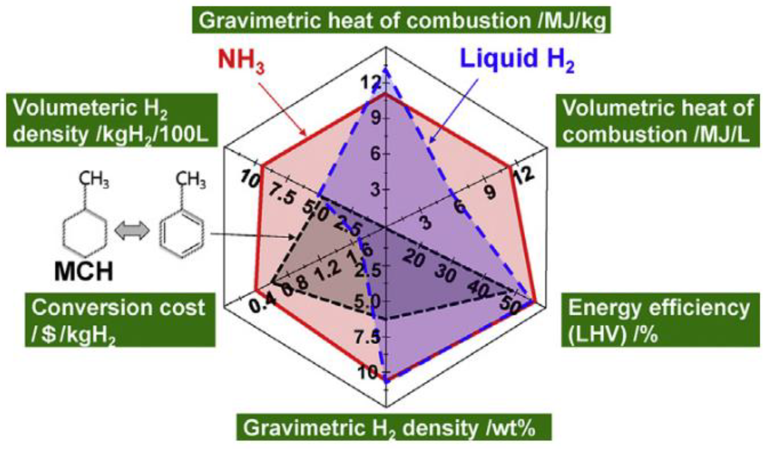
Another chemical hydrogen storage method is liquid ammonia storage. Liquid ammonia storage involves synthesizing nitrogen and hydrogen into ammonia through chemical reactions, which can then be reversibly decomposed into nitrogen and hydrogen using a catalyst, thus serving as a carrier for hydrogen storage, there are distinct advantages, as illustrated in Figure 3 [25,26,27,28,29,30]. The implementation of liquid ammonia-based hydrogen storage faces multiple challenges. Economic viability, environmental sustainability, and regulatory/policy constraints must be carefully addressed [31]. Notably, technical barriers remain critical: the interconversion of ammonia and hydrogen involves processes such as catalytic membrane reactors, thermochemical methods, non-thermal plasma techniques, solar-driven decomposition, and electrolysis, all of which fundamentally rely on redox (reduction–oxidation) catalytic mechanisms [32]. However, the required temperature and pressure conditions for efficient ammonia–hydrogen conversion are highly demanding [27]. Additionally, catalysts play an indispensable role in these processes [33]. As an upstream industry in hydrogen production, the development of appropriate catalysts will advance the viability of ammonia as a hydrogen carrier [34,35]. These challenges collectively hinder the practical deployment of liquid ammonia-based hydrogen storage systems.
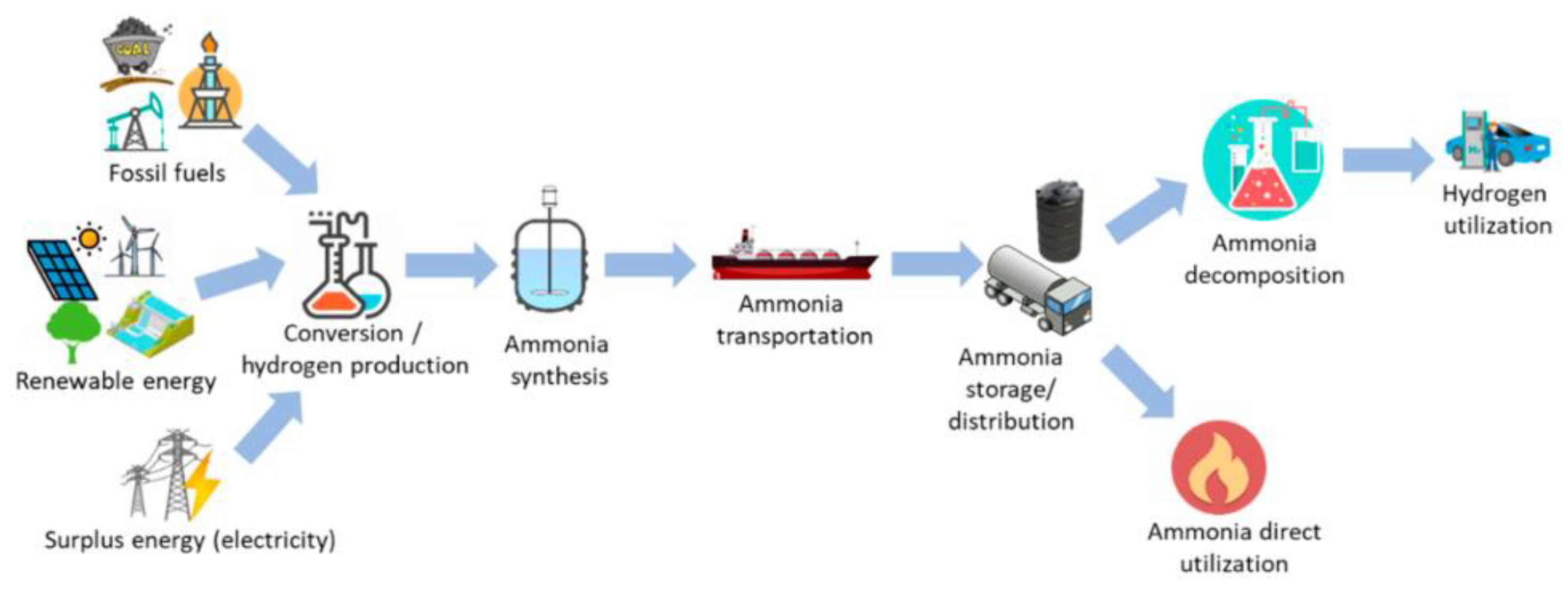
Unlike other chemical hydrogen storage methods, liquid ammonia hydrogen storage does not introduce new carbon and avoids carbon dioxide emissions. The decomposition of ammonia into nitrogen and hydrogen does not result in atmospheric pollution. Simultaneously, the liquefaction conditions of ammonia are simpler compared to those of hydrogen. The critical temperature of liquid ammonia is −33.4 °C, and the critical pressure is 11.25 MPa. Achieving storage conditions for liquid ammonia is easier compared to those for liquid hydrogen. Hydrogen storage in liquid ammonia plays a crucial role in the transregional transport of energy. As illustrated in Figure 4, this represents an energy conversion form with ammonia as the carrier. Utilizing fossil fuels, wind energy, solar energy, and hydropower generation, hydrogen is produced through the electrolysis of water. Subsequently, ammonia is synthesized with nitrogen using a catalyst, compressed into liquid ammonia for transregional transport, and then hydrogen is produced by cracking using a catalyst to participate in further energy conversion processes. The utilization of an ammonia energy storage system for energy conversion enables cross-temporal, large-scale storage and mitigates power plant pollutants. It addresses the temporal and seasonal limitations of wind and photovoltaic power generation, facilitating cross-seasonal and long-term energy storage.
In addition, liquid ammonia can serve as a standalone energy supply for participation in the energy conversion process [36,37]. Ammonia, composed of nitrogen and hydrogen, produces nitrogen and water upon complete combustion. It represents a crucial pathway toward achieving low-carbon and decarbonization goals and promoting the transition to decarbonized energy systems [38,39]. Ammonia can serve as a green fuel for vehicles, boasting an energy density second only to gasoline and liquefied petroleum gas (LPG). As a sustainable fuel, ammonia offers potential benefits and technical advantages for vehicle power generation [40,41,42]. Additionally, it can also be utilized in submarines and ships [43,44,45]. Despite the limited studies on ammonia as an energy application, it remains a key pathway toward achieving a low-carbon future.
The unique properties of hydrogen and ammonia pose certain safety challenges. Regarding hydrogen, the current predominant method for energy storage and utilization is high-pressure gaseous hydrogen storage, driven by the pursuit of higher energy density and greater economy, along with the technical maturity of hydrogen storage methods. The working pressure of high-pressure hydrogen storage tanks ranges from 35 to 70 MPa. Enhancing hydrogen storage pressure yields high economic benefits but also introduces significant risks. The safe use of high-pressure hydrogen necessitates that the design of high-pressure storage tanks considers material degradation due to hydrogen embrittlement and repeated filling stress, leading to potential ruptures, high-pressure hydrogen ejections, and hydrogen leakage diffusion in the operational environment. Due to hydrogen’s low ignition energy and wide explosion limits, it is susceptible to explosion accidents, posing significant hazards.
The risks associated with ammonia are primarily manifested in four aspects. Firstly, the health hazards of ammonia, including frostbite and toxicity, are comparable to those of liquid hydrogen, LNG, and carbon monoxide. Exposure to external ammonia sources through ingestion, inhalation, direct contact with the skin, or contact with the eyes leads to ammonia toxicity in susceptible individuals. Ammonia toxicity results in various harmful acute and chronic effects on patients. Ammonia is exposed in various ways, and gas leakage can occur during its production, storage, or transportation. Secondly, ammonia is flammable and poses a risk of explosion [28]. Thirdly, ammonia is corrosive. When combined with water to form ammonia water, it can corrode metals. Fourthly, ammonia exists as a gas at room temperature. Upon leakage from a hydrogen storage container, ammonia will escape as a gas. To enhance energy density, ammonia is applied in a pressurized and liquefied form. Following the leakage of the ammonia storage container, liquid ammonia will be released, causing significant harm. Particularly for liquid ammonia, when it participates in energy conversion as an energy storage carrier, a small amount of ammonia residue may remain in the hydrogen gas produced after the cracking of liquid ammonia [27]. Compared to single-component gases, this hybrid gas poses greater hazards.
In conclusion, when hydrogen and ammonia become the primary components of the future energy structure, safety remains a critical factor limiting their development. Clarifying the safety throughout the entire process of hydrogen and ammonia application is a fundamental task to advance the development of the hydrogen and ammonia energy system. Special attention should be given to the safety concerning hydrogen and ammonia diffusion and the risk of explosions during their use. This paper will comprehensively review the existing research on hydrogen and ammonia diffusion processes, explosion mechanisms, and prevention and detection techniques, providing theoretical support for the efficient development of the hydrogen and ammonia energy system.

2. Research Progress of Hydrogen Application Safety

2.1. Research on Hydrogen Leakage Safety

The occurrence of a hydrogen explosion is predicated on hydrogen reaching the explosive limit in air, and the extent and severity of the explosion are influenced by the area and concentration formed by hydrogen diffusion following a leak. Investigating the diffusion behavior of hydrogen following accidental leaks is crucial for effectively reducing the likelihood of explosion incidents. Currently, research on hydrogen diffusion employs experimental and simulation methods, focusing on how internal and external environmental parameters affect hydrogen diffusion behavior.
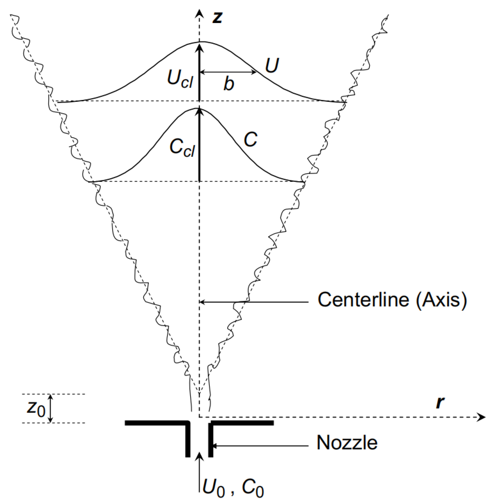
Hydrogen under varying initial conditions exhibits distinct motion modes upon exiting the leakage hole. Currently, existing research on circular hole leakage is more comprehensive. When the leakage flow rate is low, hydrogen forms a steady, vertically symmetric buoyant-free jet upon exiting a circular hole in the vertical direction, as depicted in Figure 5. Here, U denotes the average velocity, U0 is the initial velocity at the exit, Ucl is the central jet velocity, C represents the hydrogen concentration (mass fraction), C0 is the initial concentration, Ccl is the central concentration, and Z0 is the undispersed jet length. When hydrogen diffuses horizontally from the circular hole, a horizontal buoyancy jet is formed, as illustrated in Figure 6. Here, θ0 is the angle of the initial jet relative to the horizontal, s and r establish a coordinate system with the jet as a reference, g is the gravity vector aligned vertically downward along the z-axis, θ is the angle between the s-axis and the horizontal plane, and φ is the azimuth angle of the s-axis within the jet’s cross-section.
When the leakage flow rate is high, hydrogen forms an under-expanded jet after exiting the leakage hole, referred to as a high-pressure under-expanded jet. This type of jet cannot be directly modeled using the low-pressure jet integral model. Simplifying a high-pressure under-expanded jet into a low-pressure jet necessitates an equivalent inlet model, commonly referred to as a ‘virtual nozzle’. Numerous studies exist on the virtual nozzle, and several scholars have proposed specific virtual nozzle models.
Depicted in Figure 7 is the virtual nozzle model proposed by Brich in 1984 [48], where dps represents the pseudo-diameter. The model assumes that the gas exists in three distinct states. LEVEL 1 represents the initial conditions of the gas, characterized by parameters P1, T1, and ρ1. LEVEL 2 corresponds to the gas conditions at the leakage hole, defined by parameters P2, T2, ρ2, and V2. LEVEL 3 describes the gas conditions at the virtual nozzle position post-leakage, characterized by parameters P3, T3, ρ3, and V3. It is assumed that V3 equals the local sound velocity. Parameters P3 and T3 are set to match the atmospheric conditions, and the entire process adheres to the mass conservation principle. The proposed model is appropriate for predicting the concentration attenuation along the jet centerline during the leakage of high-pressure natural gas ranging from 2 to 70 bar.
In this model, Brich assumed that the airflow velocity at the virtual nozzle position equaled the local sound velocity. To address this issue, he introduced a modified model in 1987 [49]. In the new model, the assumption regarding airflow velocity was eliminated, and the momentum conservation equation was incorporated. The model proposed by Ewan in 1985 is analogous to Brich’s model from 1984. The distinction lies in the fact that it posits that the temperature T3 at the virtual nozzle equals the temperature T2 at the leakage outlet [50]. In 2002, Yüceil introduced a virtual nozzle model with greater degrees of freedom, which assumes only that the pressure of the airflow at the virtual nozzle outlet equals the ambient pressure, while the velocity, temperature, and diameter at the outlet remain unknown [51].
Research on non-circular hole leakage remains relatively limited. The jet shape of non-circular holes, such as rectangular or slit-shaped openings, is complex, with variations in the initial kinetic energy distribution resulting in a wider diffusion range and higher velocity [52,53]. For instance, leakage from a rectangular hole may enhance turbulent mixing due to an uneven momentum distribution [54,55]. However, most of the existing research has focused on circular holes, while studies on the dynamic leakage behavior—such as transient pressure distribution and turbulence characteristics—and the effects of complex geometric structures in non-circular holes remain insufficient.
The theoretical study of the diffusion model of hydrogen after exiting the leakage hole provides a preliminary prediction of hydrogen diffusion. However, in practice, the diffusion distribution of hydrogen after leakage is influenced by various internal and external environmental parameters, including leakage flow, initial pressure, initial temperature, geometric parameters of the leakage hole, ventilation, obstacles, and other factors.
When hydrogen leaks upward continuously in an unobstructed space for a brief period, a stable concentration field forms rapidly around the leakage source [56]. If the release duration is sufficiently long, the hydrogen concentration will undergo three stages during the release process: rapid growth, slow growth, and a relatively stable stage [57,58,59,60,61,62,63]. During the diffusion process, the leaked hydrogen tends to rise and delaminate towards the top of the space [64]. Research indicates that a lower leakage source position facilitates the formation of a high hydrogen concentration cloud near the ground, whereas a higher leakage source position promotes the upward diffusion of the combustible cloud. In large-scale spaces, an increase in leakage velocity reduces the dispersion time of hydrogen, leading to a significant variation in concentration distribution. Changes in the leakage direction will affect the interaction between hydrogen and the walls, subsequently altering the diffusion behavior of hydrogen [65,66,67,68]. In a small-scale space (<1 m3), the gas is more likely to accumulate in the upper portion of the space, resulting in higher hydrogen concentrations and a longer time to reach a stable state. Wind accelerates the diffusion of hydrogen. Under natural ventilation, the hydrogen concentration increases rapidly after leakage but accumulates in the walls and corners [69]. Compared to longitudinal wind conditions, transverse wind energy is more effective in reducing the hydrogen concentration [70]. Forced ventilation significantly prevents hydrogen accumulation. Strong winds of 10 m/s and above reduce hydrogen concentration levels in the vicinity of the leakage position to below the lower flammability limit. The closer the blowing position is to the leakage hole, the faster the hydrogen concentration decreases [71,72]. The presence of obstacles influences the accumulation of hydrogen. Compared to the process of liquid hydrogen leakage and diffusion under barrier-free conditions, placing obstacles in the upwind direction accelerates the diffusion rate of hydrogen, while placing obstacles in the downwind direction leads to hydrogen cloud accumulation near the ground. The influence of obstacles on hydrogen diffusion behavior increases as the distance from the obstacle to the leakage position decreases. In a semi-open space, hydrogen leaks and diffuses within a hydrogenation station. The shape and volume of the combustible hydrogen cloud are influenced by the obstacles in the leakage direction, hydrogen storage pressure, and wind speed. Obstacles in the leakage direction are congested, resulting in an irregular shape and large volume of the combustible gas cloud [73].
In an open space, the temperature influences the hydrogen diffusion pattern. The diffusion process of cryogenic hydrogen in an open space manifests in three forms: forced convection, mixed convection (forced and natural convection), and natural convection. Under the mixed convection mechanism, the temperature distribution within the gas cloud is discontinuous, and the cloud shape exhibits periodic characteristics. Under continuous leakage conditions, the maximum distance and height of the cloud ultimately stabilize periodically. Under ventilation conditions, increasing the windward wind speed reduces the maximum and stable volumes of the combustible hydrogen cloud and decreases the time required to reach these volumes. The size of the horizontal warning area and the positive warning area of hydrogen decreases with increasing wind speed, and the shape changes accordingly. Upon cessation of leakage, the combustible hydrogen cloud rapidly disperses and disappears. In an unventilated space, the influence of obstacles on hydrogen dispersion varies with the dispersed phase. In a naturally ventilated space, the hydrogen concentration is higher on the side with obstacles compared to the side without obstacles [74]. The presence of wind facilitates the formation of a recirculation zone near the obstacle. As the wind speed increases, the recirculation zone shifts downward along the obstacle, enhancing the accumulation of hydrogen near the obstacle [75]. The distance between the obstacle and the leakage port significantly affects hydrogen diffusion. As the distance decreases, the influence of the obstacle on hydrogen diffusion increases [76]. During hydrogen leakage, the change in hydrogen cloud concentration aligns well with the Reynolds number of the flow field. The diffusion of hydrogen is influenced by devices surrounding the high-pressure hydrogen storage tank, leading to uneven hydrogen concentration distribution in the flow field. During a combustion explosion, the gradients of the shockwave parameters and turbulent kinetic energy exhibit significant changes.
Hydrogen energy vehicles and ships represent a significant application of hydrogen energy in the transportation sector. For fuel cell vehicles and ships, the leakage rate, leakage location, ventilation, and the presence of obstacles influence the leakage and diffusion process of hydrogen. Among these factors, ventilation significantly impacts the leakage process. Specifically, lateral wind energy is more effective in reducing hydrogen concentration levels [68,70,74,76,77,78,79,80,81,82,83]. In the underground garage, the initial release rate of hydrogen is the primary factor influencing the distribution of hydrogen concentration. Additionally, the change in leakage direction affects the interaction between hydrogen and wall surfaces, subsequently altering the diffusion behavior of hydrogen. The presence of top obstacles leads to increased local hydrogen concentration. The hydrogen diffusion behavior in hydrogen refueling stations for fuel cell vehicles and ships is analogous to hydrogen diffusion in an open space. Several scholars have investigated the influence of wind speed and leakage location. The study found that low altitudes tend to form turbulent zones, and the upwind area also poses an explosion risk. As the ambient wind speed increases, the diffusion rate of hydrogen clouds increases. Changes in the hydrogen leakage direction directly influence its diffusion behavior, leading to significant differences in the distribution area of hydrogen–air mixture clouds.
Currently, theoretical research on hydrogen leakage primarily focuses on circular hole leakage. Limited studies have examined leakage hole shapes, such as non-circular holes, and theoretical diffusion models primarily provide only preliminary predictions of hydrogen dispersion under simplified conditions. There is a lack of theoretical discussion on long-term diffusion behavior under complex conditions, and the generalizability of existing prediction models remains limited.

2.2. Research on the Safety of Hydrogen Explosion

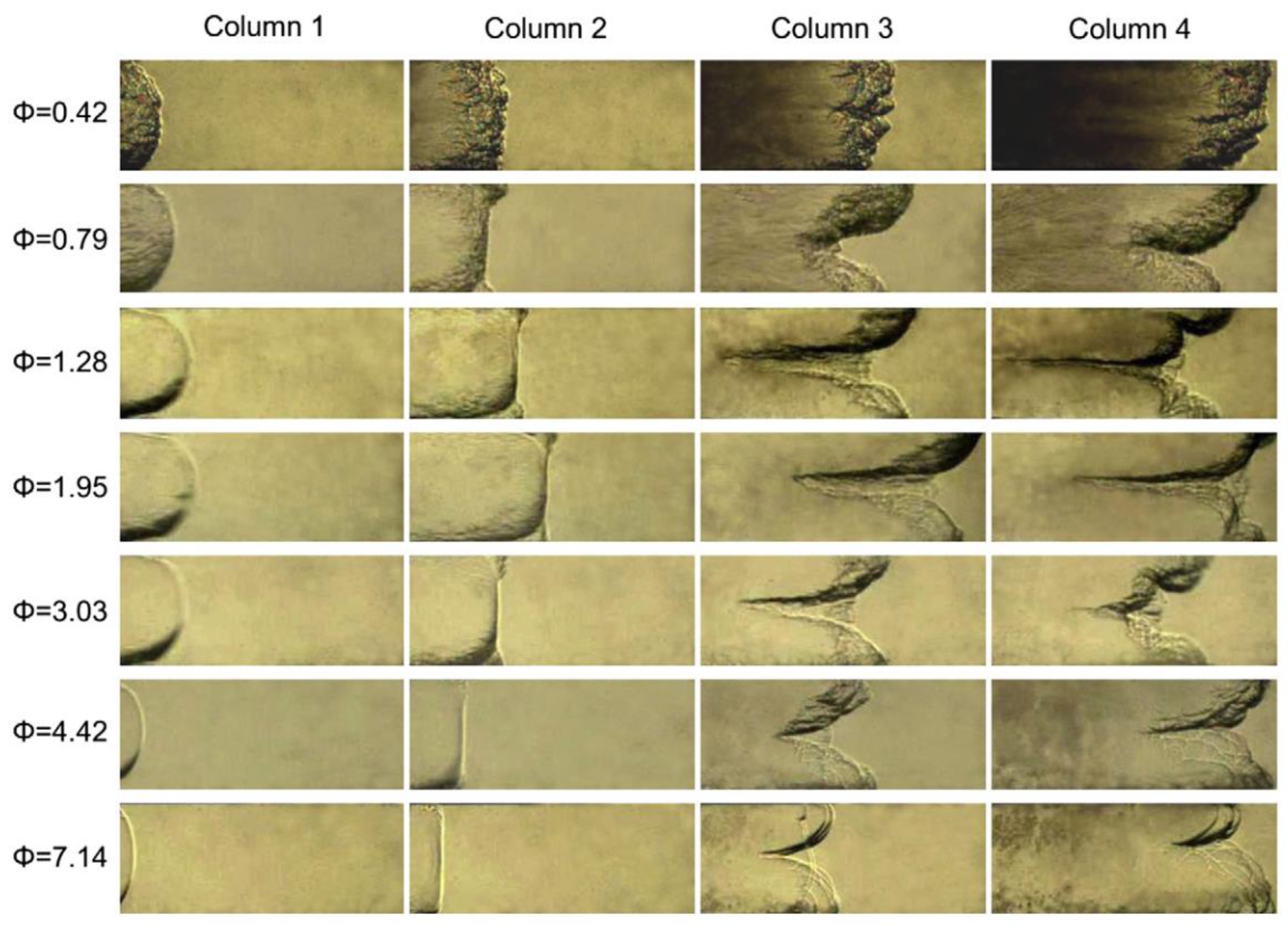
Currently, research on the combustion and explosion safety of hydrogen primarily focuses on the propagation and pressure variation characteristics of hydrogen flames in pipelines. The flame forms a tulip flame as it propagates in the pipeline. The evolution process of the tulip flame is divided into four stages: the first stage is a spherical flame, generated at the ignition stage; the second stage is a finger-shaped flame, generated after ignition and unaffected by the inner wall of the pipeline. The third stage is a planar flame. When the flame skirt touches the side wall of the pipe, the flame surface area decreases, forming a planar flame. The fourth stage is the tulip flame formation, as shown in Figure 8 [84,85].
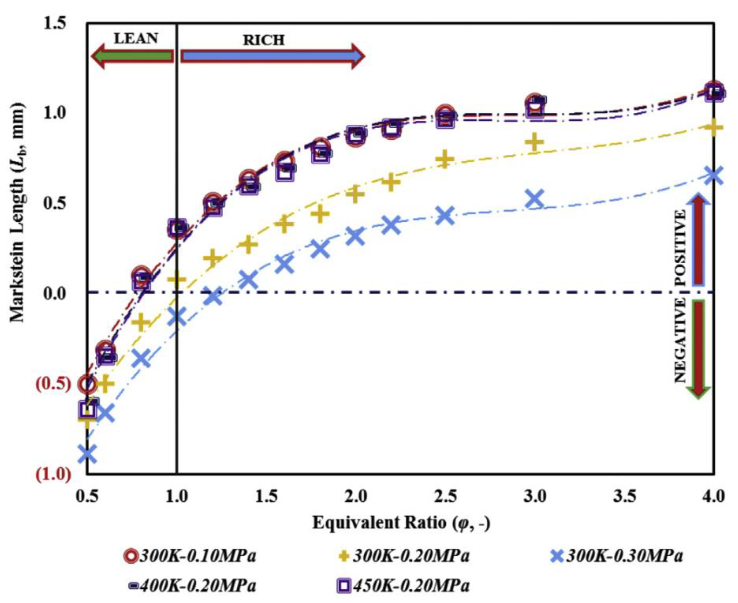
Flame stability is influenced by Rayleigh–Taylor (R–T) instability and Darrieus–Landau (D–L) instability (hydrodynamic instabilities). The R–T instability induces interpenetration between fluid regions of differing densities, while the D–L instability arises from gas expansion caused by heat release during combustion. This phenomenon generates hydrodynamic perturbations that amplify disturbances at the flame front [86]. In a closed tube, the unstable distorted tulip flames (DTFs) in the hydrogen–air premixed flame propagation process, initiated by planar ignition, is caused by the combined effect of pressure wave-driven vortex motion and Rayleigh–Taylor (R–T) instability, while subsequent DTFs are caused by reverse flow and Rayleigh–Taylor (R–T) instability [87,88]. The Markstein length, a critical parameter extensively studied in flame propagation research, characterizes the stretch rate’s influence on laminar flame speed. This parameter serves as a key indicator of premixed laminar flame stability, with higher values corresponding to enhanced flame stability. Temperature changes significantly influence the hydrogen–air flame propagation law. Large expansion ratios and pressure rise rates at low temperatures can simultaneously promote Darrieus–Landau (D–L) instability and Rayleigh–Taylor (R–T) instability, significantly increase the flame surface area, and accelerate the flame propagation in hydrogen–air mixed gas at low temperatures [89].
Currently, the Markstein length parameter is a key focus in studies on flame propagation characteristics. The Markstein length characterizes the effect of the stretch rate on the laminar flame speed and serves as an indicator of premixed laminar flame stability. A higher Markstein length value indicates greater flame stability. However, the Markstein length is sensitive to the equivalence ratio and initial pressure but is relatively insensitive to the initial temperature. As shown in Figure 9 [90], at low pressures, the behavior of the laminar combustion speed exhibits irregularity, depending on the equivalence ratio range [91,92]. Under high-temperature and high-pressure conditions, the laminar burning velocity increases with the rising initial temperature and decreases with the increasing initial pressure. As the initial pressure increases, the onset of cellular instability occurs earlier, and the Markstein length decreases, indicating an increase in flame instability [93]. The initial pressure influences the unstretched laminar burning velocity and flame instability, with the flame stability decreasing as the initial pressure increases. The Markstein length of low-hydrogen content fuel is particularly sensitive to variations in the initial pressure [94,95,96,97,98]. For propylene/hydrogen/air mixtures, the unstretched flame propagation speed and laminar combustion speed increase with the rising initial temperature and decrease with the increasing initial pressure. As the initial pressure increases, the onset time of cellular instability advances while the critical radius and Markstein length decrease, indicating greater hydrodynamic instability [99].
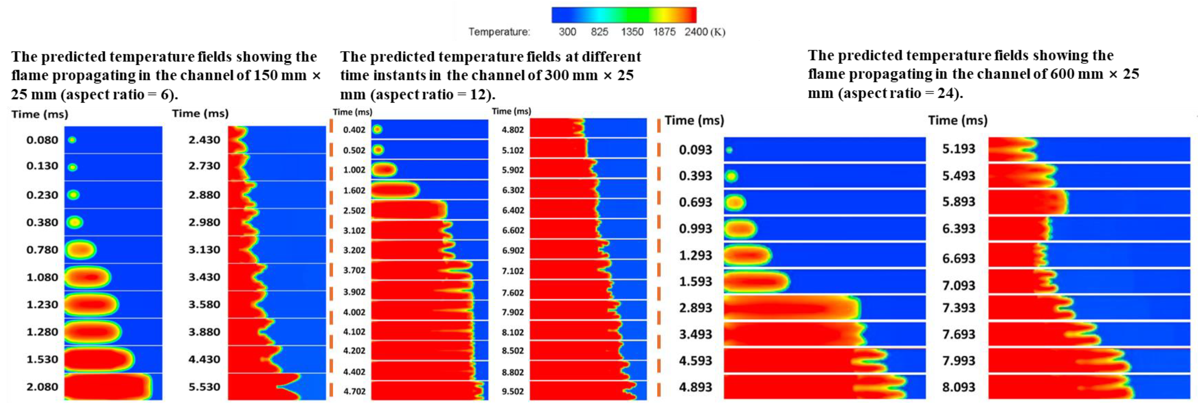
Parameters such as the pipe shape and opening rate also affect the development of the flame. Due to the enhancement of the pressure wave and the interaction between the flame and pressure wave, the hydrogen/air premixed flame in the closed rectangular channel changes with the aspect ratio. When the aspect ratio changed from 6 to 12 to 24, the flame shape and pressure propagation law change more dramatically, as shown in Figure 10 [100]. Crack bifurcation in the pipeline significantly increases the fracture opening rate, thereby controlling the strength and shape of the explosion wave. The initiation and propagation of cracks lead to the formation of a shockwave from the burst pipe, which is then strengthened by subsequent compression waves [101].
The concentration gradient and ignition position influence the dynamics of unrestricted non-uniform hydrogen explosions. The maximum overpressure, overpressure rise rate, and positive impulse increase significantly as the concentration gradient decreases. When ignition occurs at different positions, flame propagation from the equivalent concentration zone to the flammable limit zone is suppressed by the concentration gradient. The explosion process triggered by central ignition is the most intense and shortest, resulting in the highest temperature [102,103]. The addition of other components also affects the combustion and explosion characteristics of hydrogen, increasing the proportion of hydrogen in the hydrogen–methane mixture, which results in an increase in the combustion speed and a widening of the flammability limit. The combustion effect of a 30% hydrogen and 70% methane mixture is optimal [94,95,104]. The hydrogen fraction, initial pressure, and equivalence ratio affect the unstretched laminar burning velocity and flame instability, and the flame stability decreases with the increasing initial pressure. For a given equivalence ratio and hydrogen blending ratio, the flame thickness is more sensitive to changes in the initial pressure than to changes in the density ratio, and the Markstein length of fuels with a low hydrogen content is more sensitive to changes in the initial pressure than fuels with a high hydrogen content [94,95,96,97,98]. For the propylene/hydrogen/air mixture, both the unstretched flame propagation speed and the unstretched laminar combustion speed increase with the increasing hydrogen blending ratio and initial temperature and decrease with the increasing initial pressure. With increasing the initial pressure, the onset time of cell instability advances, and the critical radius and Markstein length decrease, indicating increased hydrodynamic instability with increasing the initial pressure. The addition of hydrogen increases the hydrodynamic instability [99]. The increase in laminar flame velocity after adding hydrogen is likely due to the increase in active free radicals in the combustion process, rather than changes in the adiabatic flame temperature [105]. The combustion and explosion flame structure of the methane/hydrogen mixture: as the hydrogen fraction increases, the flame propagates while maintaining its tulip shape, accompanied by a small amplitude of oscillation. As shown in Figure 11 [106], when the hydrogen volume fraction is 20%, the peak overpressure and maximum flame speed of the premixed gas are maximized, reaching 1.266 MPa and 168 m/s [107].
In the presence of obstacles, the methane/hydrogen explosion flame undergoes splitting and merging as it propagates through dual-channel obstacles. The fusion behavior of the split flame varies depending on the obstacle position and barrier ratio, manifesting as either complementary fusion or merging. As the obstacle distance from the ignition point increases, the maximum velocity initially rises and then declines, reaching more than five times its original value [108]. The presence of obstacles significantly affects the flame propagation law, and the arrangement of obstacles influences the flame propagation speed and explosion pressure. As the number of obstacles increases, the Kelvin–Helmholtz (K–H) instability and R–T instability intensify, the more pronounced the flame stretching, and the greater the turbulence intensity of the flame propagation. The shape of the obstacle influences the overpressure peak (Figure 12). The triangular obstacle induces a higher overpressure peak, which is 7% and 30% higher than that of the square and circular obstacles, respectively. In a closed rectangular pipe with obstacles, as the number of obstacles changes, the flame transitions into hemispherical, finger, tongue, quasi-plane, and mouth flames. The coupling of the flame–obstacle flow field and its hydrodynamic phenomena determines the deformation of the flame and the change in propagation velocity. The results of the dimensional analysis indicate that the drag coefficient effectively characterizes the influence of the obstacle shape. The size of the obstacle also influences the flame propagation behavior. For granular obstacles, smaller-diameter obstacles exhibit a more effective suppression of the chemical equivalence than nearby flames [103,109,110,111,112,113].
The presence of the venting hole also influences hydrogen flame propagation. Flame propagation behavior in the pipeline is significantly influenced by the venting pressure of the hole. The maximum overpressure inside the pipeline increases with the rupture pressure, and the location of the maximum internal overpressure is influenced by this pressure. Flame propagation is delayed in a pipe with both ends open, while such a configuration also facilitates the propagation process. When the flame is ignited at one end of the opening and propagates to the other end, the mitigation effect becomes more pronounced [114]. The discharge process induces displacement of the discharge device, and the peak displacement is significantly influenced by the hydrogen volume fraction, increasing with its rise. The peak acceleration is also influenced by the ignition position. The central ignition scenario results in higher peak acceleration than the back end ignition scenario. The effect of the number of obstacles on the dynamic response of the structure is non-monotonic. When the hydrogen flame is released from the spherical device, both the flame front distance and propagation velocity increase with the length of the venting tube [115]. When the explosion venting port size is large, hydrogen venting in a confined space leads to the formation of a large combustible gas cloud, which is ignited by the ejected flame, resulting in an external explosion. A monotonic relationship exists between the maximum overpressure and concentration at various positions outside the vent, while a non-monotonic relationship is observed between the overpressure change rate and concentration at different positions near the venting port. The improved venting efficiency of the large aperture venting port causes significant distortion of the flame front as it passes through, while increasing the distance between the venting port and ignition end reduces the degree of flame front distortion. Additionally, the venting effects differ significantly, depending on the size of the venting port.
The detonation of hydrogen generates thermal radiation and shockwave damage to the surrounding buildings and individuals. In large-scale hydrogen detonations, the closer an object is to the detonation source, the greater the negative drag pulse, while the positive drag impulse is generated at a greater distance from the source [116]. In a confined space, the shockwave overpressure caused by detonation is significantly higher [117]. In open spaces, such as hydrogen refueling stations, the front of the combustible cloud in the external area is spherical at low wind speeds, significantly increasing the probability of a hydrogen explosion. Additionally, an increase in ignition delay time may intensify the explosion. When the ignition delay time is long, the backpropagation of two flame fronts and explosion overpressure can be observed, as shown in Figure 13 [118]. A significant correlation exists between the overpressure following a hydrogen explosion in a full-scale hydrogen filling station, ignition time, and the distance from the ignition point [119]. There are variations in the propagation patterns of unconstrained hydrogen explosion overpressure in different directions. The flame exhibits the fastest upward propagation speed and the slowest downward propagation speed, resulting in an irregularly spherical flame shape [120].
The overpressure propagation of gas cloud explosions exhibits self-similarity in a space; however, due to the influence of acoustic characteristics, built-in obstacles significantly increase the positive overpressure peak, while the absolute value of the negative overpressure peak remains smaller than the positive peak [121]. The size of the gas cloud and the presence of built-in obstacles affect the development of the gas cloud explosion. Both the maximum explosion pressure and maximum flame front velocity increase with the scale of the gas cloud. Built-in obstacles increase the rate of increase in both flame front velocity and explosion pressure [122]. Flame acceleration caused by obstacles generates two overpressure peaks. A prediction model for forward overpressure and impulse peaks, excluding built-in obstacles, is proposed [123]. Flame acceleration in hydrogen cloud explosions with built-in obstacles is attributed to the combined effects of flame instability and obstacle-induced turbulence [124]. Flat petal-shaped flames were observed at the doors of both obstacle-free and obstacle-containing chambers, which differs significantly from the mushroom-shaped flame morphology observed in traditional large opening venting explosions and the associated rolling vortex bubble venting [125]. When a hydrogen cloud explosion occurs in a long, congested area and flame deceleration takes place, the maximum pressure may be generated by the pressure wave produced during an earlier stage of the explosion process. If these pressure waves are tightly coupled with the enhanced pressure peak of the flame front, they may contribute to flame deceleration [126]. The flame propagation characteristics of gas cloud explosions are influenced by both the internal and external environmental parameters. In an inert gas atmosphere, the effect of thermal diffusivity on laminar burning velocity is significantly greater than that of the adiabatic flame temperature [127]. When external turbulence is present and the flame radius exceeds a certain critical value, flame acceleration due to external turbulence is attributed to the coupling of flame instability and external turbulence [128]. As the intensity of the external turbulence increases, the flame accelerates and explosion overpressure rises gradually [129]. A study of the heat energy propagation characteristics and hazard effects of hydrogen cloud explosions reveals that the temperature–distance curve of the hydrogen explosion flame is of the ‘Z’ type [130].
Research on the combustion and explosion characteristics of hydrogen is conducted from two perspectives: the propagation dynamics of combustion and explosion flames and the assessment of their destructive potential. Research primarily focuses on the propagation characteristics and pressure response of combustion and explosion flames within pipelines. The flame propagation and development process is influenced by multiple factors, including temperature, pressure, pipe geometry, opening ratio, obstacles, composition, concentration gradient, and ignition position. For large-scale hydrogen detonations, factors such as the distance from the detonation source, spatial constraints, and ventilation influence the development of the detonation shockwave. Comparatively, research on the propagation dynamics of combustion flames is more extensive, whereas the assessment of their destructive potential remains limited. A more in-depth investigation of this aspect would help mitigate the destructive potential of combustion flames.

2.3. Research on Hydrogen Leakage Detection Technology

Since the lower explosion limit of hydrogen is 4%, timely detection of hydrogen after leakage and the establishment of the relationship between hydrogen concentration distribution and temporal changes in a space will provide substantial support for the safe utilization of hydrogen energy. Currently, hydrogen detection is primarily categorized into two types: electrical measurement and optical measurement.
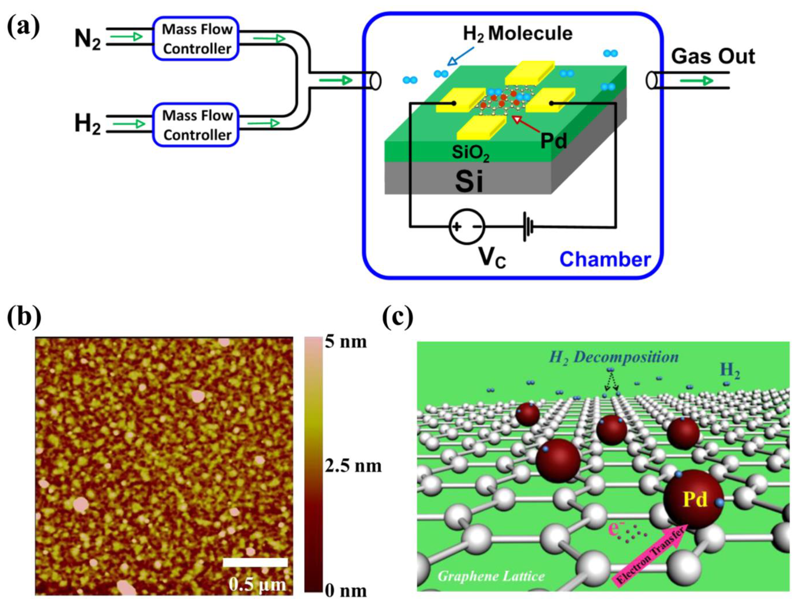
The electrical measurement method involves using a hydrogen sensor to determine the concentration. The current hydrogen concentration sensors are primarily of the conductivity type. These sensors feature a straightforward measurement principle and low cost. The conductivity-type hydrogen concentration sensors utilize metals, semiconductor metal oxides, carbon-based materials, and other substances, as shown in Figure 14 [131,132,133].
Research on metal-based conductive hydrogen concentration sensors began earlier. As early as 1990, Canadian scholars carried out research work on the availability of Pd-based hydrogen concentration sensors [134]. Scharnagl pointed out that Pd/Ni is a very promising room temperature hydrogen detection material [135]. The nanostructured palladium film can be used for rapid response hydrogen detection microsensors with a very low H2 detection threshold, wide dynamic range, and very good selectivity [136]. Metal-polymer hybrid nanomaterials enable ultrafast hydrogen detection in plasma. The polymer coating lowers the apparent activation energy for hydrogen adsorption and desorption in plasma nanoparticles, aligning with the optimal volume-to-surface ratio of the nanoparticle-based signal converter. The sensor achieves a sub-second response time [137].
Metal oxides are employed as the detection elements in hydrogen sensors. The sensor, composed of titanium dioxide nanoarray tubes, selectively detects low-concentration hydrogen at room temperature, demonstrating complete reversibility, repeatability, high selectivity, negligible drift, and a wide dynamic range [138]. Under vacuum conditions, sintered cerium oxide nanoparticles detect hydrogen, converting gas adsorption into electrical signals with high sensitivity and durability [139]. The combination of metal oxides and metals enhances the sensor performance. Rumiche investigated the gas sensing properties of hydrogen by preparing a nanostructured sensing device based on anodic aluminum oxide (AAO) nanopores. The response time of the AAO nanopore/Pd nanostructure detector was significantly reduced, the nanostructure schematic is illustrated in Figure 15 [140]. The p-type semiconductor copper oxide film is suitable for hydrogen detection, exhibiting good response and recovery capabilities in an air atmosphere [141]. Titanium oxide is also effective for hydrogen detection. The gas sensor, based on solgel-grown nanocrystalline p/TiO2 film, is suitable for rapid hydrogen detection [142]. The UV-assisted hydrogen sensor, composed of Pd nanoparticle-modified hollow TiO2 nanospheres, exhibits high sensitivity, selectivity, and long-term stability for hydrogen [143]. Under the modification of Pd, SnO2 can also exhibit good hydrogen detection performance. After modification with Pd nanoparticles, the hydrogen sensing response is significantly increased [144]. Pd modification significantly improves the hydrogen gas sensing performance, with ultrafast response and high selectivity [145]. Zinc titanate thin films were prepared on Si/SiO2 substrates by the spin-coating process with Al as the electrode, which has excellent hydrogen gas sensing properties [146].
Zinc oxide is widely used in the fabrication of hydrogen sensors. The design of a hierarchical zinc oxide (ZnO) microstructure modified by silver (Ag) nanoparticles has become an effective method to improve the gas sensing performance of hydrogen [147]. The hydrogen gas sensing performance of Pd @ ZnO core–shell nanoparticles (CSNPs) is affected by the core and surface area. The sensor has a high selectivity for hydrogen in the interference target gas. This is because the high content of metal Pd0 in CSNPs and the high specific surface area of the core–shell material also provide a large number of active sites for accelerating the sensing reaction [148]. At low temperatures, Pd-modified ultrathin ZnO nanosheets demonstrate p-type sensing behavior. The enhanced sensing performance of Pd-modified sensors is attributed to the presence of Pd/ZnO heterojunctions, the formation of PdHx, and the high catalytic activity of Pd [149]. MoS2 nanosheet-coated ZnO thin-film sensors exhibit exceptional error-free repeatability [150]. The Pd–ZnO double-layer structure sensor is effective for hydrogen detection at room temperature. The detection limit (LOD) of the double-layer sensor is approximately 4.5 times higher than that of the single-layer ZnO film and nearly twice that of the single-layer Pd film.
Carbon-based materials can also be used for the detection of hydrogen. Graphene sensors have also been proven to be high-performance hydrogen sensors with a high gas response, excellent linearity, and good repeatability and selectivity, The operating principle of the multifunctional graphene sensor for H₂ detection is illustrated in Figure 16 [151]. A novel resistive gas sensor based on a single-walled carbon nanotube (SWNT) as an active sensing element has been evaluated for hydrogen detection [152]. Carbon nanotubes with a Pd/CNT/n∂-Si structure are suitable for hydrogen measurements in an open environment [153]. The detection performance of 2D hybrid Pd/rGO for hydrogen is greatly affected by temperature, humidity, and ultraviolet irradiation [154]. Platinum plating on graphene will affect the hydrogen gas sensing performance. The graphene sensor with a platinum layer thickness of 1 nm has the highest hydrogen sensitivity and also exhibits good hydrogen detection selectivity [155]. Graphene/Ag2S composite nanostructures can also be used for hydrogen measurement, with high gas sensitivity and a fast response time, which is attributed to the various properties and synergistic effects between Ag2S/GNS hybrids [156].
Optical measurement methods encompass hydrogen detection through optical fiber sensors and flow field visualization using schlieren technology.
Hydrogen detection using optical fiber sensors was initially employed in the aerospace industry. Nanofiber tapers coated with palladium films can rapidly detect hydrogen [157]. A hydrogen concentration below the explosion limit can be detected swiftly and accurately based on the reflectivity change of the palladium micromirror deposited on the output end face of a multimode fiber, in accordance with the concentration and temperature differences [158]. The fiber optic sensor has distributed measurement capabilities, allowing for the detection of hydrogen leakage points along the fiber [159]. Additionally, Mg-based metal hydrides can be utilized in the fabrication of optical fiber hydrogen detectors, with Mg/Ti-based alloys offering enhanced optical and switching properties [160]. The combination of Pd-based catalysts will show a better detection performance. Incorporating silver into the Pd catalytic layer enhances the sensing performance in oxygen-rich mixed gases and ambient air [161]. Subsequent research has focused on the combined application of Pd and optical fiber sensors. A nanostructured Pd-long period fiber grating integrated optical sensor can be employed for hydrogen detection. The Pd layer, fabricated through sputtering deposition, consists of 30–40 nm nanocrystals. The sensor exhibits a rapid response time, though its recovery speed is relatively slow. The sensor retains its functionality after several cycles of hydrogen detection and recovery [162]. A thicker palladium layer (560 nm), prepared via magnetron sputtering, yields higher sensitivity. As demonstrated in Figure 17, it effectively detects the concentration of trace amounts of hydrogen dissolved in the transformer’s insulating oil, with a sensitivity of up to 13.5 ppm/pm [163]. The incorporation of additives can enhance the performance of these sensors. Adding polyimide to the adhesive layer increases the reliability of the sensor, with minimal impact from external factors on the sensor performance [164].
In addition to optical fiber sensors, there have also been new optical hydrogen detectors in recent years. A novel optical detector capable of indicating a hydrogen presence at low concentrations through reversible and tunable color changes shows promise for chemical, biochemical, and biomedical applications [165]. A palladium-coated optical fiber sensor alone fails to meet the performance criteria for rapid response time and resistance to deactivation caused by poisoning. The large-tilt fiber Bragg grating facilitates faster hydrogen measurement response times and greater resistance to deactivation through its narrow bandwidth cladding mode [166]. Recent advancements include the proposal of photoinduced thermoelastic spectroscopy for hydrogen detection. Sensors developed through this method exhibit rapid response times, high sensitivity, and a highly linear response to the H2 concentration levels [167].
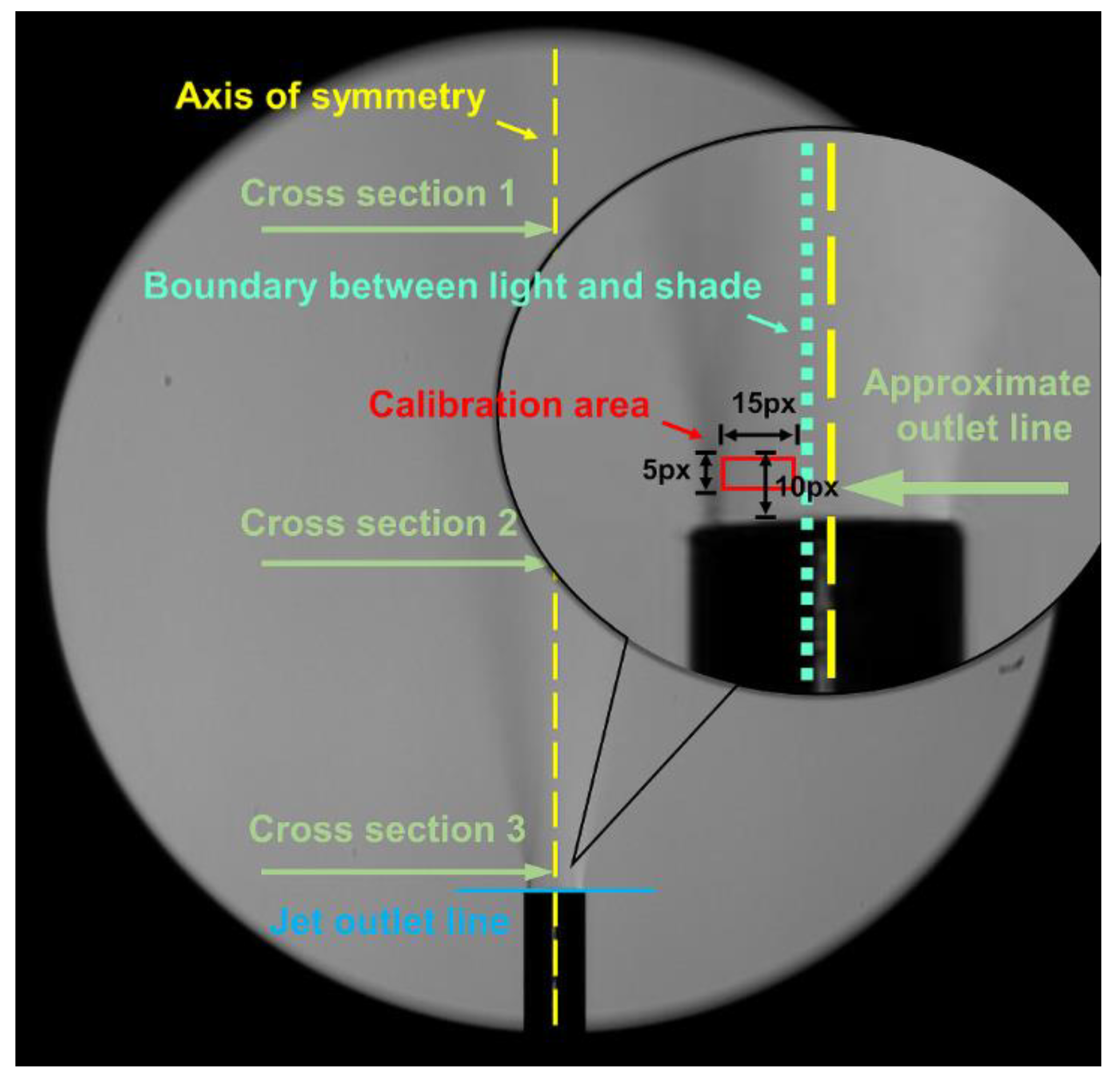
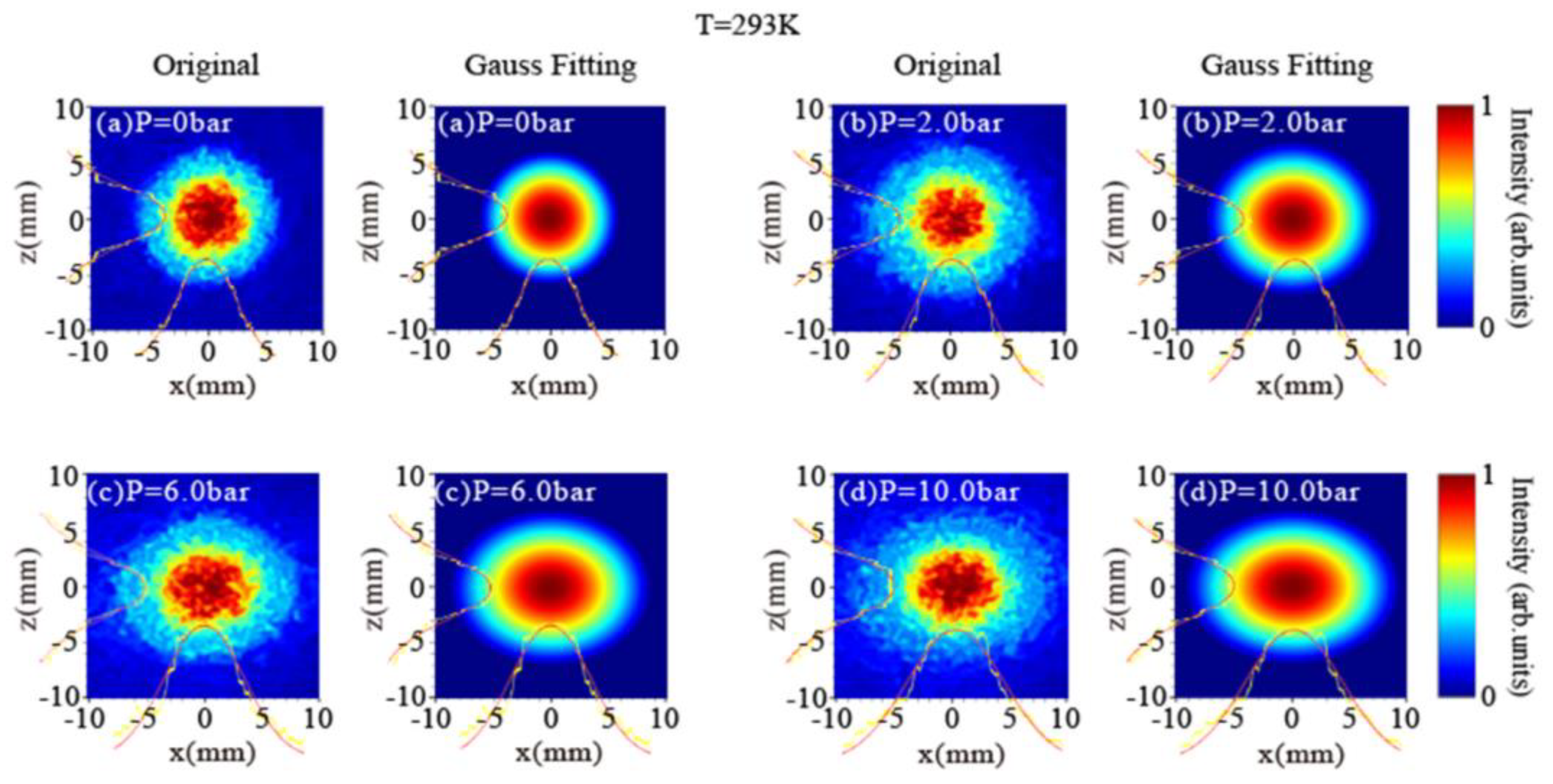
Figure 18 illustrates a flow field visualization method based on schlieren technology. This method serves as a novel approach for detecting hydrogen leakage and measuring the concentration. It relies on the refractive index differences caused by variations in the gas concentration to establish the relationship between display effects and concentration. A novel visualization and concentration calibration method enables the derivation of a concentration attenuation formula in both axial and radial directions by extracting quantitative concentration data from the schlieren image, which characterizes hydrogen leakage and distribution. The attenuation formula effectively represents the jet concentration distribution, with the average error in the processing results being less than 10% [168]. By employing schlieren technology, the hydrogen concentration is decoupled from the complex schlieren image data, and the mapping relationship between the hydrogen leakage concentration and the schlieren image gray level is determined through experimental procedures, enabling a quantitative hydrogen concentration analysis [169]. The advanced background oriented schlieren (BOS) technology enables hydrogen leakage detection across both low-power and high-power peaks. It offers benefits such as simple equipment, low cost, high sensitivity, fast response, and high reliability [170]. The dual-channel interferometric self-imaging method enables the simultaneous visualization of hydrogen leakage density and pressure. The two-way propagation of the laser beam within the hydrogen jet enhances the phase sensitivity, and the object is relayed between each pass to preserve the spatial resolution. The deformation of the laser beam profile in the horizontal direction increases linearly with the increasing jet pressure. The laser effect is depicted in Figure 19 [171]. The intensity projection of the laser beam also facilitates the visualization of the hydrogen jet. The hydrogen jet acts as a gas lens with adjustable laser beam energy. Changes in the jet pressure alter the full width at half-maximum of the spectrum, thereby influencing the intensity distribution of the laser beam after passing through the hydrogen jet. By analyzing the intensity data of the laser after it passes through the hydrogen jet, the change in jet pressure can be estimated [172].
Electrical and optical measurement techniques are essential for hydrogen detection. Electrical measurement primarily relies on conductive hydrogen concentration sensors, utilizing metals, semiconductor metal oxides, carbon-based materials, and other compounds. Optical measurement techniques encompass optical fiber sensors and schlieren-based flow field visualization. Conductive hydrogen concentration sensors exhibit high gas sensitivity and rapid response. However, the detection range of existing conductive sensors remains limited; they enable rapid detection of low hydrogen concentrations but struggle with high concentrations. Extensive research on optical fiber sensors in optical measurements has demonstrated their capability for the rapid and accurate detection of hydrogen concentrations below the explosion limit. Schlieren-based flow field visualization technology has recently emerged. The refractive index variations caused by gas concentration changes are utilized to establish the correlation between visualization effects and concentration, offering high sensitivity, rapid response, and strong reliability. The detection limit of conductance-type hydrogen concentration sensors requires further enhancement, and their linear accuracy needs improvement. Single-point measurement techniques fail to accurately capture the spatial distribution of the hydrogen concentration. Schlieren-based flow field visualization imposes strict requirements on environmental parameters, making it a key focus of future research.

3. Research Progress of Ammonia Application Safety

3.1. Research Progress of Ammonia Application Safety

Currently, research on the leakage and diffusion of liquid ammonia is primarily concentrated in China, with most studies employing numerical simulations. The research primarily focuses on the leakage and diffusion processes of liquid ammonia refrigerant in cold storage. The oxygen density is lower than that of air. After leakage from the pipe section or high-pressure equipment, the pressure difference between the internal and surrounding environments provides the initial kinetic energy for the ammonia leakage, creating a distinct jet trajectory near the leakage port. The ammonia moves rapidly upwards and diffuses [173]. The ammonia concentration change during leakage and diffusion in a confined space occurs in three stages: linear growth, fluctuation, and stable growth [174]. When obstacles are present near the leakage source, the dangerous concentration range extends from the release source to the obstacles and outward from them. Lethal concentration and explosion areas exist only near the release source. The liquid ammonia pool formed after colliding with obstacles does not evaporate rapidly [175,176,177]. As the wind speed increases, the influence of obstacles on the affected area becomes more pronounced [178]. When the leakage direction is horizontal or upward, the ammonia concentration is highest at the four corners of the top of the plant under undisturbed conditions, with the concentration at the top exceeding that at ground level. When the leakage direction is downward, the ammonia concentration on the ground initially rises sharply before gradually diffusing upward [179]. The exhaust port is more effective when positioned at the top of the plant rather than on the side wall, and the smaller the distance between the exhaust port and the ammonia accumulation area, the better the ventilation effect [180]. The location of the leakage hole and wind speed influence the diffusion process of liquid ammonia [181].
When the leakage occurs at the top of the tank, increasing the ambient wind speed causes the ammonia gas cloud with a high concentration threshold to be blown over a greater distance [182]. When the leakage occurs at the bottom of the storage tank, the ammonia concentration at each position along the X-positive direction increases with the increasing ambient wind speed, and the air transport effect is enhanced. The concentration and area of the ammonia gas cloud exhibit a decreasing trend. At different wind speeds, the diffusion distance of ammonia along the Y-axis decreases gradually as the wind speed increases. Therefore, wind speed can accelerate the diffusion rate of ammonia in the downwind direction and increase the area affected by gas diffusion. It can also accelerate the dilution rate of gas in the atmosphere, preventing the accumulation of ammonia concentration during the diffusion process. When the wind direction aligns with the direction of the leakage source, increasing the wind speed makes the effects of ammonia diffusion more pronounced, and the diffusion distance and hazardous area decrease [183,184,185,186]. Leakage time significantly influences the distribution of the ammonia concentration. As time increases, the ammonia concentration at each point in space gradually rises before stabilizing. The concentration increase follows different paths at various points, and the time for the concentration to stabilize also varies [187,188]. When the leakage port is located on the side of the storage tank, higher wind speeds result in stronger external air forces, increasing the diffusion distance of the ammonia gas cloud in the downwind direction, enhancing the dilution in the air, and reducing the concentration of ammonia gas that exceeds the safety threshold. Leakage pressure affects the leakage process. The initial leakage velocity in the low-pressure pipeline is low, and the duration of the ejection stage is brief. Under the influence of eddy current disturbance in the confined space, the jet direction is deflected when ammonia gas leaks in various directions. The diffusion area concentrates on the upwind side of the leakage source. Leakage at the top of the tank has a minimal effect on the ammonia concentration near the ground. When leakage occurs at the bottom, high concentrations of ammonia gas are primarily concentrated near the ground [189,190]. When leakage occurs in the liquid ammonia tank, the leakage aperture significantly influences the post-leakage diffusion concentration. The leakage rate of the ammonia tank and the gas diffusion concentration at the same location increase with the aperture size. When the leakage aperture exceeds 20 mm, the ammonia leakage diffusion concentration and range increase significantly. However, when the leakage aperture exceeds 90 mm, it is no longer the primary factor affecting diffusion [191,192]. Changes in the leakage height also affect the leakage process. The higher the leakage height, the smaller the influence on the ground ammonia concentration [193]. As the tank pressure increases, the apparent diffusion range of ammonia gas increases but eventually decreases [191].
Currently, research on ammonia diffusion is primarily focused on the leakage and dispersion of liquid ammonia, while studies on the leakage and dispersion process of gaseous ammonia remain unexplored. Future research on the leakage and dispersion process should be conducted based on practical ammonia applications.

3.2. Research on the Explosion Characteristics of Ammonia Gas

Currently, research on the combustion and explosion characteristics of ammonia primarily focuses on its flame parameters. These parameters include the laminar burning velocity, Markstein length, and minimum critical radius. Existing studies primarily investigate the laminar burning velocity of ammonia flames.
The laminar burning velocity is a crucial parameter for characterizing ammonia combustion flames. It is influenced by the mixture composition, oxygen content, and initial pressure. The maximum laminar burning velocity in a NH3/O2 mixture is 1.09 m/s. H2 enhances the laminar burning velocity of NH3/air flames. The laminar burning velocity increases exponentially with the rising hydrogen content, with a pronounced acceleration effect in the initial combustion stage. The tensile sensitivity of the laminar premixed flame increases with the hydrogen content, reaching its maximum near the stoichiometric ratio [194]. Additionally, the ratio of turbulent to laminar burning velocity rises with the increasing turbulence intensity [195,196,197,198,199,200,201,202,203,204,205,206,207]. Under high-pressure conditions, the ratio of the CH4/NH3/air turbulent premixed flame combustion rate to the unstretched laminar combustion rate decreases as the ammonia ratio increases, and the flame area also decreases with a higher ammonia content. CH4 has minimal influence on increasing the laminar combustion rate [208]. Under oxygen-enriched and high-pressure conditions, the laminar burning velocity rises with the increasing oxygen content but declines with a higher initial pressure. Compared to the hydrogen ratio and equivalence ratio, the initial pressure has the weakest effect on the laminar burning velocity of a H2/NH3/air mixture [209,210,211,212]. The laminar burning velocity is also influenced by the degree of ammonia dissociation, increasing monotonically with higher dissociation levels. When ammonia is fully dissociated, the maximum laminar burning velocity increases from 7.9 cm/s to 228 cm/s, with the equivalence ratio corresponding to the peak value shifting from 1.1 to 1.6 [213].
Currently, several studies have investigated the Markstein length and minimum critical radius of ammonia combustion flames. The propagation of NH3/O2 combustion flames is primarily governed by inertial forces, with gravity playing a secondary role [214]. The minimum critical radius in NH3/O2 mixtures is 1.8 cm and decreases with the increasing initial pressure [211,215]. The Markstein length of ammonia combustion increases with a higher equivalence ratio but decreases with the increasing initial pressure. In CH4/NH3/air mixtures, the Markstein length increases with the rising ammonia concentration [216,217]. As the equivalence ratio increases, the Markstein length and critical instability radius increase monotonically [218].
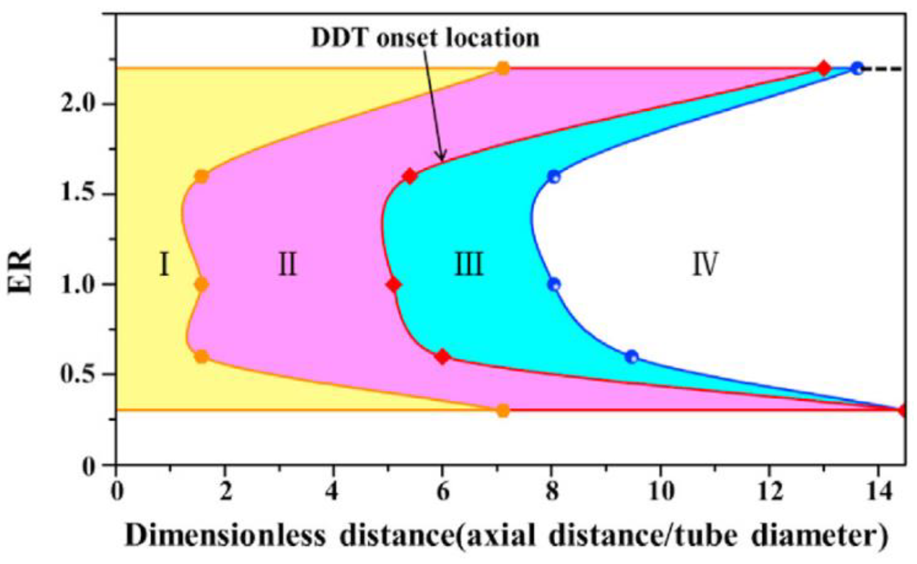
The deflagration-to-detonation transition (DDT) is a crucial process for evaluating the performance of ammonia deflagration. In a stoichiometric NH3/O2 mixture, the flame front and leading shockwave propagate at different speeds until they become tightly coupled at a stable velocity. The DDT process in the NH3/O2 mixture consists of four stages: the slow propagation stage, the flame and pressure wave acceleration stage, the rapid propagation and detonation wave formation stage, and the detonation wave self-sustaining propagation stage, as shown in Figure 20 [219]. An increase in the pressure and hydrogen concentration enhances the chemical reaction rate of ammonia combustion, accelerates the flame, induces noticeable oscillations, and advances the onset of the deflagration-to-detonation transition. Consequently, the detonation wave propagation velocity increases, with a gradual rise as the hydrogen ratio increases [220,221]. A higher hydrogen content results in an increasingly distorted flame, as shown in Figure 21 [222]. The wrinkle rate rises with the increasing ammonia concentration and turbulence intensity [199]. The pulse detonation frequency increases with the equivalence ratio under lean combustion conditions, peaks under stoichiometric conditions, and decreases as the equivalence ratio rises further under rich combustion conditions [223].
Research on the combustion and explosion characteristics of ammonia primarily focuses on the combustion and explosion parameters. Potential combustion and explosion scenarios in practical engineering applications remain unexamined, and further investigation is required into the development characteristics and destructive potential of combustion and explosion flames.

4. Conclusions and Foresight

4.1. Research Progress Summary

To achieve the dual carbon goals of ‘carbon peak’ and ‘carbon neutrality’ and to transform the existing pyramid energy structure, the application of hydrogen and ammonia as new energy fuels is a crucial aspect of energy structure transformation and an essential step toward efficient, clean, and orderly development. Safety is a critical factor influencing the future application of new energy fuels. In particular, the distinct physical and chemical properties of hydrogen and ammonia exacerbate the risks associated with their use. Currently, research on the safety of hydrogen and ammonia applications primarily focuses on the leakage and diffusion processes of hydrogen and liquid ammonia, hydrogen leakage detection technology, and the explosion processes of hydrogen and ammonia.
Research on the hydrogen leakage and diffusion process began earlier, and significant progress has been made in both theoretical analysis and engineering applications. The leakage and diffusion process of hydrogen exhibits different motion control states influenced by the initial state parameters. During the release process, the hydrogen concentration undergoes three stages: rapid growth, slow growth, and relative stability. The virtual nozzle model effectively explains this process. Furthermore, the diffusion of hydrogen is influenced by external environmental parameters, such as temperature, pressure, ventilation, and obstacles, which affect the diffusion process. The timely detection of hydrogen leakage significantly reduces the probability of hydrogen explosion accidents. Current detection technologies include electrical and optical measurement technologies. Electrical measurement technology has been under development for a long time. Conductive hydrogen concentration sensors include metals, semiconductor metal oxides, carbon-based materials, and other substances. It is characterized by low cost and a simple measurement principle. However, this detection technology still has the disadvantages of long response times, low detection accuracy, and significant sensitivity to external environmental parameters. Optical detection technology includes hydrogen detection using optical fiber sensors and flow field visualization based on schlieren technology. Hydrogen detection technology using optical fiber sensors determines the hydrogen concentration by analyzing reflectivity changes at the optical fiber output end. Flow field visualization technology based on schlieren technology uses the refractive index difference caused by changes in the gas concentration to determine the relationship between the display effect and concentration. Currently, there are relatively few studies on ammonia leakage. The existing research primarily uses simulation methods, focusing on the leakage and diffusion processes of liquid ammonia refrigerant in cold storage. Studies show that ammonia quickly moves upward and diffuses after leakage. The change in ammonia concentration in a confined space occurs in three stages: linear growth, fluctuation, and stable growth. Additionally, the diffusion process of liquid ammonia is significantly influenced by parameters such as obstacles and ventilation.
Currently, the research on hydrogen explosion safety mainly focuses on the propagation characteristics and pressure response of hydrogen flames in pipelines. The unstable distorted tulip flames (DTFs) formed in a closed tube are caused by the combined effects of eddy currents and Rayleigh–Taylor (R–T) instability. The propagation and development of the flame are influenced by several factors, including temperature, pressure, pipe shape, opening rate, obstacles, concentration gradient, and ignition position. For large-scale hydrogen detonation, the distance from the detonation source influences the development of the detonation shockwave. The overpressure propagation of a gas cloud explosion in an unrestricted space is self-similar. The size of the gas cloud affects the development of the gas cloud explosion. The maximum explosion pressure and maximum flame front velocity increase as the cloud scale increases. The addition of other components also affects the combustion and explosion characteristics of hydrogen. Increasing the hydrogen proportion in the hydrogen–methane mixture leads to an increase in the combustion rate and a broadening of the flammability limit. The hydrogen fraction, initial pressure, and equivalence ratio influence the unstretched laminar burning velocity and flame instability. For the explosion flame structure of methane–hydrogen components, with an increase in the hydrogen fraction, the flame propagates while maintaining its tulip shape, accompanied by small amplitude oscillations.
Currently, research on the combustion and explosion characteristics of ammonia primarily focuses on its combustion and explosion flame parameters. The Markstein length of ammonia combustion increases with the equivalence ratio and decreases with the increasing initial pressure. The critical radius of the ammonia–oxygen flame decreases as the initial pressure increases. In the ammonia-oxygen mixed system, the deflagration-to-detonation transition (DDT) process consists of four stages: slow propagation, flame and pressure wave acceleration, rapid propagation and detonation wave formation, and detonation wave self-sustaining propagation. Compared to methane, hydrogen promotes ammonia flame, and increasing the hydrogen content in the fuel mixture causes the flame to become increasingly distorted. The characteristics of the combustion flame are influenced by the stoichiometric ratio. The pulse detonation frequency increases with the equivalence ratio under lean combustion conditions, peaks at stoichiometric conditions, and gradually decreases under rich combustion conditions.

4.2. Research Prospect

As an efficient hydrogen storage carrier, ammonia inevitably coexists with hydrogen energy conversion. The current research does not account for the accidental leakage of hydrogen–ammonia mixtures in practical applications, nor has it sufficiently studied their diffusion dynamics, detection technology, and explosion hazards. Future research on the safety of the hydrogen–ammonia application process should focus on the following areas:
  • Research on the diffusion characteristics of hydrogen–ammonia mixtures should investigate their diffusion mechanisms, with a focus on the impact of the initial environmental conditions, external parameters, obstacles, and ventilation.
  • It is necessary to conduct research on the deflagration characteristics of hydrogen–ammonia mixtures. Based on the study of flame propagation and evolution in pipelines, it is essential to add research on deflagration characteristics and hazard assessments for scenarios where accidents may occur during the integrated application of hydrogen and ammonia.
  • It is necessary to enhance the new gas concentration detection technology, improve the accuracy and speed of gas concentration detection, and be able to respond quickly to possible leakage situations.
  • It is necessary to optimize the gas concentration detection technology based on schlieren imaging, clarify the jet development process after the leakage of hydrogen–ammonia mixtures, establish the attenuation formula of hydrogen–ammonia mixtures, and achieve concentration predictions.

Author Contributions

Conceptualization, Z.Z. (Zilong Zhang); methodology, Z.Z. (Zilong Zhang); validation, Z.Z. (Zhaotong Zhang), Y.O. and J.S.; investigation, J.Z.; resources, D.Z.; data curation, Y.W.; writing—original draft preparation, Z.Z. (Zilong Zhang); writing—review and editing, Z.Z. (Zilong Zhang) and Y.Z.; visualization, D.Z.; supervision, B.L. and L.X.; project administration, J.Y., H.X. and L.X.; funding acquisition, J.Z. and L.X. All authors have read and agreed to the published version of the manuscript.

Funding

This research was funded by the Postgraduate Research & Practice Innovation Program of Jiangsu Province, grant number KYCX24_0626, this funding belongs to Zilong Zhang; the China Postdoctoral Science Foundation, grant number 2023M741715, this funding belongs to Jing Zhang; and the Natural Science Foundation of Jiangsu Province of China, grant number BK20241488, this funding belongs to Jing Zhang.

Data Availability Statement

No new data were created or analyzed in this study. Data sharing is not applicable to this article.

Conflicts of Interest

The authors declare no conflicts of interest.

Abbreviations

The following abbreviations are used in this manuscript:
DTFsUnstable distorted tulip flames
DDTDeflagration-to-detonation transition
R–TRayleigh–Taylor
K–HKelvin–Helmholtz
D–LDarrieus–Landau

References

  1. Duro, J.A.; Padilla, E. Inequality across Countries in Energy Intensities: An Analysis of the Role of Energy Transformation and Final Energy Consumption. Energy Econ. 2011, 33, 474–479. [Google Scholar] [CrossRef]
  2. Michael, T. (Ed.) Evolution in the Global Energy Transformation to 2050; Energy subsidies; International Renewable Energy Agency: Abu Dhabi, United Arab Emirates, 2020; ISBN 978-92-9260-125-6. [Google Scholar]
  3. Vanegas Cantarero, M.M. Of Renewable Energy, Energy Democracy, and Sustainable Development: A Roadmap to Accelerate the Energy Transition in Developing Countries. Energy Res. Soc. Sci. 2020, 70, 101716. [Google Scholar] [CrossRef]
  4. Hafner, M.; Tagliapietra, S. (Eds.) The Geopolitics of the Global Energy Transition; Lecture Notes in Energy; Springer International Publishing: Cham, Switzerland, 2020; Volume 73, ISBN 978-3-030-39065-5. [Google Scholar]
  5. Blondeel, M.; Bradshaw, M.J.; Bridge, G.; Kuzemko, C. The Geopolitics of Energy System Transformation: A Review. Geogr. Compass 2021, 15, e12580. [Google Scholar] [CrossRef]
  6. Shu, Y.; Chen, G.; He, J.; Zhang, F. Building a New Electric Power System Based on New Energy Sources. Chin. J. Eng. Sci. 2021, 23, 61. [Google Scholar] [CrossRef]
  7. Dyczko, A.; Kamiński, P.; Stecuła, K.; Prostański, D.; Kopacz, M.; Kowol, D. Thermal and Mechanical Energy Storage as a Chance for Energy Transformation in Poland. Polityka Energ. Energy Policy J. 2021, 24, 43–60. [Google Scholar] [CrossRef]
  8. Liu, Y.; Tan, Q.; Zhang, X.; Han, J.; Guo, M. How Does Electricity Supply Mode Affect Energy-Water-Emissions Nexus in Urban Energy System? Evidence from Energy Transformation in Beijing, China. J. Clean. Prod. 2022, 366, 132892. [Google Scholar] [CrossRef]
  9. Cheba, K.; Bąk, I.; Szopik-Depczyńska, K.; Ioppolo, G. Directions of Green Transformation of the European Union Countries. Ecol. Indic. 2022, 136, 108601. [Google Scholar] [CrossRef]
  10. Veziroğlu, T.N.; Şahi, S. 21st Century’s Energy: Hydrogen Energy System. Energy Convers. Manag. 2008, 49, 1820–1831. [Google Scholar] [CrossRef]
  11. Jain, I.P. Hydrogen the Fuel for 21st Century. Int. J. Hydrog. Energy 2009, 34, 7368–7378. [Google Scholar] [CrossRef]
  12. Johnston, B.; Mayo, M.C.; Khare, A. Hydrogen: The Energy Source for the 21st Century. Technovation 2005, 25, 569–585. [Google Scholar] [CrossRef]
  13. Marchenko, O.V.; Solomin, S.V. The Future Energy: Hydrogen versus Electricity. Int. J. Hydrog. Energy 2015, 40, 3801–3805. [Google Scholar] [CrossRef]
  14. Singla, M.K.; Nijhawan, P.; Oberoi, A.S. Hydrogen Fuel and Fuel Cell Technology for Cleaner Future: A Review. Environ. Sci. Pollut. Res. 2021, 28, 15607–15626. [Google Scholar] [CrossRef] [PubMed]
  15. Stępień, Z. A Comprehensive Overview of Hydrogen-Fueled Internal Combustion Engines: Achievements and Future Challenges. Energies 2021, 14, 6504. [Google Scholar] [CrossRef]
  16. Jiang, Z.; Gao, X. Quantification and Evaluation of China’s Hydrogen Automobile Industry Policy. Int. J. Hydrog. Energy 2024, 56, 757–768. [Google Scholar] [CrossRef]
  17. Wei, Q.S.; Zhang, X.; Oh, B.S. The Effect of Driving Cycles and H2 Production Pathways on the Lifecycle Analysis of Hydrogen Fuel Cell Vehicle: A Case Study in South Korea. Int. J. Hydrog. Energy 2021, 46, 7622–7633. [Google Scholar] [CrossRef]
  18. Medisetty, V.M.; Kumar, R.; Ahmadi, M.H.; Vo, D.-V.N.; Ochoa, A.A.V.; Solanki, R. Overview on the Current Status of Hydrogen Energy Research and Development in India. Chem. Eng. Technol. 2020, 43, 613–624. [Google Scholar] [CrossRef]
  19. Khan, U.; Yamamoto, T.; Sato, H. Consumer Preferences for Hydrogen Fuel Cell Vehicles in Japan. Transp. Res. Part Transp. Environ. 2020, 87, 102542. [Google Scholar] [CrossRef]
  20. Apostolou, D.; Welcher, S.N. Prospects of the Hydrogen-Based Mobility in the Private Vehicle Market. a Social Perspective in Denmark. Int. J. Hydrog. Energy 2021, 46, 6885–6900. [Google Scholar] [CrossRef]
  21. Tarhan, C.; Çil, M.A. A Study on Hydrogen, the Clean Energy of the Future: Hydrogen Storage Methods. J. Energy Storage 2021, 40, 102676. [Google Scholar] [CrossRef]
  22. Usman, M.R. Hydrogen Storage Methods: Review and Current Status. Renew. Sustain. Energy Rev. 2022, 167, 112743. [Google Scholar] [CrossRef]
  23. Pu, L.; Yu, H.; Dai, M.; He, Y.; Sun, R.; Yan, T. Research Progress and Application of High-Pressure Hydrogen and Liquid Hydrogen in Storage and Transportation. Chin. Sci. Bull. 2022, 67, 2172–2191. [Google Scholar] [CrossRef]
  24. Lebedeva, O.; Kultin, D.; Kalenchuk, A.; Kustov, L. Advances and Prospects in Electrocatalytic Hydrogenation of Aromatic Hydrocarbons for Synthesis of “Loaded” Liquid Organic Hydrogen Carriers. Curr. Opin. Electrochem. 2023, 38, 101207. [Google Scholar] [CrossRef]
  25. Kojima, Y.; Yamaguchi, M. Ammonia as a Hydrogen Energy Carrier. Int. J. Hydrog. Energy 2022, 47, 22832–22839. [Google Scholar] [CrossRef]
  26. Aziz, M.; Wijayanta, A.T.; Nandiyanto, A.B.D. Ammonia as Effective Hydrogen Storage: A Review on Production, Storage and Utilization. Energies 2020, 13, 3062. [Google Scholar] [CrossRef]
  27. Klerke, A.; Christensen, C.H.; Nørskov, J.K.; Vegge, T. Ammonia for Hydrogen Storage: Challenges and Opportunities. J. Mater. Chem. 2008, 18, 2304. [Google Scholar] [CrossRef]
  28. Kojima, Y. Safety of Ammonia as a Hydrogen Energy Carrier. Int. J. Hydrog. Energy 2024, 50, 732–739. [Google Scholar] [CrossRef]
  29. Makepeace, J.W.; He, T.; Weidenthaler, C.; Jensen, T.R.; Chang, F.; Vegge, T.; Ngene, P.; Kojima, Y.; De Jongh, P.E.; Chen, P.; et al. Reversible Ammonia-Based and Liquid Organic Hydrogen Carriers for High-Density Hydrogen Storage: Recent Progress. Int. J. Hydrog. Energy 2019, 44, 7746–7767. [Google Scholar] [CrossRef]
  30. Ulucan, T.H.; Akhade, S.A.; Ambalakatte, A.; Autrey, T.; Cairns, A.; Chen, P.; Cho, Y.W.; Gallucci, F.; Gao, W.; Grinderslev, J.B.; et al. Hydrogen Storage in Liquid Hydrogen Carriers: Recent Activities and New Trends. Prog. Energy 2023, 5, 012004. [Google Scholar] [CrossRef]
  31. Olabi, A.G.; Abdelkareem, M.A.; Al-Murisi, M.; Shehata, N.; Alami, A.H.; Radwan, A.; Wilberforce, T.; Chae, K.-J.; Sayed, E.T. Recent progress in green ammonia: Production, applications, assessment; barriers, and its role in achieving the sustainable development goals. Energy Convers. Manag. 2023, 277, 116594. [Google Scholar] [CrossRef]
  32. Mashhadimoslem, H.; Safarzadeh Khosrowshahi, M.; Delpisheh, M.; Convery, C.; Rezakazemi, M.; Aminabhavi, T.M.; Kamkar, M.; Elkamel, A. Green Ammonia to Hydrogen: Reduction and Oxidation Catalytic Processes. Chem. Eng. J. 2023, 474, 145661. [Google Scholar] [CrossRef]
  33. Lamb, K.E.; Dolan, M.D.; Kennedy, D.F. Ammonia for Hydrogen Storage; a Review of Catalytic Ammonia Decomposition and Hydrogen Separation and Purification. Int. J. Hydrog. Energy 2019, 44, 3580–3593. [Google Scholar] [CrossRef]
  34. Li, X.; Wang, Q.; Wu, S.; Hu, Z.; Bai, J. Critical Upstream Technologies for Hydrogen Energy Industry: Research Progress on Ammonia Decomposition Catalysts. Sustain. Chem. Pharm. 2024, 38, 101492. [Google Scholar] [CrossRef]
  35. Mukherjee, S.; Devaguptapu, S.V.; Sviripa, A.; Lund, C.R.F.; Wu, G. Low-Temperature Ammonia Decomposition Catalysts for Hydrogen Generation. Appl. Catal. B Environ. 2018, 226, 162–181. [Google Scholar] [CrossRef]
  36. Valera-Medina, A.; Xiao, H.; Owen-Jones, M.; David, W.I.F.; Bowen, P.J. Ammonia for Power. Prog. Energy Combust. Sci. 2018, 69, 63–102. [Google Scholar] [CrossRef]
  37. Guiberti, T.F.; Pezzella, G.; Hayakawa, A.; Sarathy, S.M. Mini Review of Ammonia for Power and Propulsion: Advances and Perspectives. Energy Fuels 2023, 37, 14538–14555. [Google Scholar] [CrossRef]
  38. Tan, H.; Sang, Z.; Tian, Y.; Peng, W.; Liu, X.; Liang, J. Ammonia as a Green Carbon-Free Fuel: A Pathway to the Sustainable Energy Economy. ACS Energy Lett. 2024, 5120–5136. [Google Scholar] [CrossRef]
  39. Jeerh, G.; Zhang, M.; Tao, S. Recent Progress in Ammonia Fuel Cells and Their Potential Applications. J. Mater. Chem. A 2021, 9, 727–752. [Google Scholar] [CrossRef]
  40. Zamfirescu, C.; Dincer, I. Ammonia as a Green Fuel and Hydrogen Source for Vehicular Applications. Fuel Process. Technol. 2009, 90, 729–737. [Google Scholar] [CrossRef]
  41. Al-Hamed, K.H.M.; Dincer, I. A Novel Ammonia Solid Oxide Fuel Cell-Based Powering System with on-Board Hydrogen Production for Clean Locomotives. Energy 2021, 220, 119771. [Google Scholar] [CrossRef]
  42. Wan, Z.; Tao, Y.; Shao, J.; Zhang, Y.; You, H. Ammonia as an Effective Hydrogen Carrier and a Clean Fuel for Solid Oxide Fuel Cells. Energy Convers. Manag. 2021, 228, 113729. [Google Scholar] [CrossRef]
  43. Machaj, K.; Kupecki, J.; Malecha, Z.; Morawski, A.W.; Skrzypkiewicz, M.; Stanclik, M.; Chorowski, M. Ammonia as a Potential Marine Fuel: A Review. Energy Strategy Rev. 2022, 44, 100926. [Google Scholar] [CrossRef]
  44. Akgun, I.; Dincer, I. Development of a Smart Powering System with Ammonia Fuel Cells and Internal Combustion Engine for Submarines. Energy 2024, 294, 130747. [Google Scholar] [CrossRef]
  45. Cheliotis, M.; Boulougouris, E.; Trivyza, N.L.; Theotokatos, G.; Livanos, G.; Mantalos, G.; Stubos, A.; Stamatakis, E.; Venetsanos, A. Review on the Safe Use of Ammonia Fuel Cells in the Maritime Industry. Energies 2021, 14, 3023. [Google Scholar] [CrossRef]
  46. El-Amin, M.F. Non-Boussinesq Turbulent Buoyant Jet Resulting from Hydrogen Leakage in Air. Int. J. Hydrog. Energy 2009, 34, 7873–7882. [Google Scholar] [CrossRef]
  47. El-Amin, M.F.; Sun, S. Horizontal H2–Air Turbulent Buoyant Jet Resulting from Hydrogen Leakage. Int. J. Hydrog. Energy 2012, 37, 3949–3957. [Google Scholar] [CrossRef]
  48. Birch, A.D.; Brown, D.R.; Dodson, M.G.; Swaffield, F. The Structure and Concentration Decay of High Pressure Jets of Natural Gas. Combust. Sci. Technol. 1984, 36, 249–261. [Google Scholar] [CrossRef]
  49. Birch, A.D.; Hughes, D.J.; Swaffield, F. Velocity Decay of High Pressure Jets. Combust. Sci. Technol. 1987, 52, 161–171. [Google Scholar] [CrossRef]
  50. Ewan, B.C.R.; Moodie, K. Structure and Velocity Measurements in Underexpanded Jets. Combust. Sci. Technol. 1986, 45, 275–288. [Google Scholar] [CrossRef]
  51. Yüceil, K.B.; Ötügen, M.V. Scaling Parameters for Underexpanded Supersonic Jets. Phys. Fluids 2002, 14, 4206–4215. [Google Scholar] [CrossRef]
  52. Kang, Y.; Ma, S.; Song, B.; Xia, X.; Wu, Z.; Zhang, X.; Zhao, M. Simulation of Hydrogen Leakage Diffusion Behavior in Confined Space. Int. J. Hydrog. Energy 2023, 53, 75–85. [Google Scholar] [CrossRef]
  53. Wang, T.; Huang, T.; Hu, S.; Li, Y.; Yang, F.; Ouyang, M. Simulation and Risk Assessment of Hydrogen Leakage in Hydrogen Production Container. Int. J. Hydrog. Energy 2023, 48, 20096–20111. [Google Scholar] [CrossRef]
  54. Kang, Y.; Ma, S.; Song, B.; Xia, X.; Wu, Z.; Zhang, X.; Zhao, M. Study on the Hydrogen Leakage Diffusion Behavior by Obstacles in Confined Spaces. Fuel 2023, 358, 130110. [Google Scholar] [CrossRef]
  55. Zhang, T.; Jiang, Y.; Wang, S.; Pan, X.; Hua, M.; Wang, Z.; Wang, Q.; Li, Y.; Jiang, J. Numerical Study on the Flow Characteristics of Pressurized Hydrogen Leaking into the Confined Space through Different Shaped Orifices. Int. J. Hydrog. Energy 2022, 47, 35527–35539. [Google Scholar] [CrossRef]
  56. Shu, Z.; Liang, W.; Zheng, X.; Lei, G.; Cao, P.; Dai, W.; Qian, H. Dispersion Characteristics of Hydrogen Leakage: Comparing the Prediction Model with the Experiment. Energy 2021, 236, 121420. [Google Scholar] [CrossRef]
  57. Xin, J.; Duan, Q.; Jin, K.; Sun, J. A Reduced-Scale Experimental Study of Dispersion Characteristics of Hydrogen Leakage in an Underground Parking Garage. Int. J. Hydrog. Energy 2023, 48, 16936–16948. [Google Scholar] [CrossRef]
  58. Cerbarano, D.; Tieghi, L.; Delibra, G.; Lo Schiavo, E.; Minotti, S.; Corsini, A. Characterization of High-Pressure Hydrogen Leakages. J. Eng. Gas Turbines Power 2024, 146, 51019. [Google Scholar] [CrossRef]
  59. Longden, T.; Beck, F.J.; Jotzo, F.; Andrews, R.; Prasad, M. ‘Clean’ Hydrogen?—Comparing the Emissions and Costs of Fossil Fuel versus Renewable Electricity Based Hydrogen. Appl. Energy 2022, 306, 118145. [Google Scholar] [CrossRef]
  60. Shu, Z.; Liang, W.; Liu, F.; Lei, G.; Zheng, X.; Qian, H. Diffusion Characteristics of Liquid Hydrogen Spills in a Crossflow Field: Prediction Model and Experiment. Appl. Energy 2022, 323, 119617. [Google Scholar] [CrossRef]
  61. Yang, N.; Deng, J.; Wang, C.; Bai, Z.; Qu, J. High Pressure Hydrogen Leakage Diffusion: Research Progress. Int. J. Hydrog. Energy 2023, 50, 1029–1046. [Google Scholar] [CrossRef]
  62. Park, J.; Kang, S.; Kim, S.; Kim, H.; Kim, S.-K.; Lee, J.H. Optimizing Green Hydrogen Systems: Balancing Economic Viability and Reliability in the Face of Supply-Demand Volatility. Appl. Energy 2024, 368, 123492. [Google Scholar] [CrossRef]
  63. Yan, Y.; Wang, Y.; Yan, J.; Zhang, H.; Shang, W. Wind Electricity-hydrogen-Natural Gas Coupling: An Integrated Optimization Approach for Enhancing Wind Energy Accommodation and Carbon Reduction. Appl. Energy 2024, 369, 123482. [Google Scholar] [CrossRef]
  64. Thawani, B.; Hazael, R.; Critchley, R. Numerical Modelling of Hydrogen Leakages in Confined Spaces for Domestic Applications. Int. J. Hydrog. Energy 2024, 56, 797–806. [Google Scholar] [CrossRef]
  65. Xu, Q.; Chen, G.; Xie, M.; Li, X.; Zhao, Y.; Su, S.; Li, S. Experimental and Numerical Studies on Hydrogen Leakage and Dispersion Evolution Characteristics in Space with Large Aspect Ratios. J. Clean. Prod. 2024, 438, 140467. [Google Scholar] [CrossRef]
  66. Xie, Y.; Liu, J.; Qin, J.; Xu, Z.; Zhu, J.; Liu, G.; Yuan, H. Numerical Simulation of Hydrogen Leakage and Diffusion in a Ship Engine Room. Int. J. Hydrog. Energy 2023, 55, 42–54. [Google Scholar] [CrossRef]
  67. Sun, R.; Pu, L.; Yu, H.; Dai, M.; Li, Y. Modeling the Diffusion of Flammable Hydrogen Cloud under Different Liquid Hydrogen Leakage Conditions in a Hydrogen Refueling Station. Int. J. Hydrog. Energy 2022, 47, 25849–25863. [Google Scholar] [CrossRef]
  68. Mao, X.; Ying, R.; Yuan, Y.; Li, F.; Shen, B. Simulation and Analysis of Hydrogen Leakage and Explosion Behaviors in Various Compartments on a Hydrogen Fuel Cell Ship. Int. J. Hydrog. Energy 2020, 46, 6857–6872. [Google Scholar] [CrossRef]
  69. Li, F.; Yuan, Y.; Yan, X.; Malekian, R.; Li, Z. A Study on a Numerical Simulation of the Leakage and Diffusion of Hydrogen in a Fuel Cell Ship. Renew. Sustain. Energy Rev. 2018, 97, 177–185. [Google Scholar] [CrossRef]
  70. Shen, Y.; Lv, H.; Zheng, T.; Liu, Y.; Zhou, W.; Zhang, C. Temporal and Spatial Evolution of Hydrogen Leakage and Diffusion from Tube Fittings on Fuel Cell Vehicles under the Effect of Ambient Wind. Renew. Sustain. Energy Rev. 2023, 185, 113596. [Google Scholar] [CrossRef]
  71. Xie, L.; Rong, Y.; Chen, J.; Yuan, F.; Long, R. Impacts of Wind Conditions on Hydrogen Leakage during Refilling Hydrogen-Powered Vehicles. Energy Storage Sav. 2023, 2, 449–458. [Google Scholar] [CrossRef]
  72. Li, X.; Xu, Y.; Li, X.; Jin, Z.; Qian, J. Effect of Wind Condition on Unintended Hydrogen Release in a Hydrogen Refueling Station. Int. J. Hydrog. Energy 2020, 46, 5537–5547. [Google Scholar] [CrossRef]
  73. Wang, Y.; Chen, Y.; Zhao, H.; Xiong, Y. Study on the Influence of Barriers in the Diffusion Process of Liquid Hydrogen Leakage. IOP Conf. Ser. Earth Environ. Sci. 2020, 546, 42–48. [Google Scholar] [CrossRef]
  74. Hou, X.; Lan, H.; Zhao, Z.; Li, J.; Hu, C.; Li, Y. Effect of Obstacle Location on Hydrogen Dispersion in a Hydrogen Fuel Cell Bus with Natural and Mechanical Ventilation. Process Saf. Environ. Prot. 2023, 171, 995–1008. [Google Scholar] [CrossRef]
  75. Qian, J.; Li, X.; Gao, Z.; Jin, Z. A Numerical Study of Hydrogen Leakage and Diffusion in a Hydrogen Refueling Station. Int. J. Hydrog. Energy 2020, 45, 14428–14439. [Google Scholar] [CrossRef]
  76. Li, Y.; Hou, X.; Wang, C.; Wang, Q.; Qi, W.; Li, J.; Zhang, X. Modeling and Analysis of Hydrogen Diffusion in an Enclosed Fuel Cell Vehicle with Obstacles. Int. J. Hydrog. Energy 2021, 47, 5745–5756. [Google Scholar] [CrossRef]
  77. Jiao, M.; Zhu, H.; Huang, J.; Zhang, X. Numerical Simulation of Hydrogen Leakage and Diffusion Process of Fuel Cell Vehicle. World Electr. Veh. J. 2021, 12, 193. [Google Scholar] [CrossRef]
  78. Xie, Y.; Lv, N.; Wang, X.; Wu, D.; Wang, S. Thermal and Fire Characteristics of Hydrogen Jet Flames in the Tunnel at Longitudinal Ventilation Strategies. Fuel 2021, 306, 121659. [Google Scholar] [CrossRef]
  79. Liu, S.; He, R. Optimization of Hydrogen Sensor Placement for Hydrogen Leakage Monitoring in the Fuel Cell Truck. J. Braz. Soc. Mech. Sci. Eng. 2023, 45, 193. [Google Scholar] [CrossRef]
  80. Lv, H.; Shen, Y.; Zheng, T.; Zhou, W.; Ming, P.; Zhang, C. Numerical Study of Hydrogen Leakage, Diffusion, and Combustion in an Outdoor Parking Space under Different Parking Configurations. Renew. Sustain. Energy Rev. 2023, 173, 113093. [Google Scholar] [CrossRef]
  81. Hao, D.; Wang, X.; Zhang, Y.; Wang, R.; Chen, G.; Li, J. Experimental Study on Hydrogen Leakage and Emission of Fuel Cell Vehicles in Confined Spaces. Automot. Innov. 2020, 3, 111–122. [Google Scholar] [CrossRef]
  82. Wang, X.; Yi, F.; Su, Q.; Zhou, J.; Sun, Y.; Guo, W.; Shu, X. Influence of Longitudinal Wind on Hydrogen Leakage and Hydrogen Concentration Sensor Layout of Fuel Cell Vehicles. Sustainability 2023, 15, 10712. [Google Scholar] [CrossRef]
  83. Tamura, Y.; Takeuchi, M.; Sato, K. Effectiveness of a Blower in Reducing the Hazard of Hydrogen Leaking from a Hydrogen-Fueled Vehicle. Int. J. Hydrog. Energy 2014, 39, 20339–20349. [Google Scholar] [CrossRef]
  84. Xiao, H.; Wang, Q.; He, X.; Sun, J.; Shen, X. Experimental Study on the Behaviors and Shape Changes of Premixed Hydrogen–Air Flames Propagating in Horizontal Duct. Int. J. Hydrog. Energy 2011, 36, 6325–6336. [Google Scholar] [CrossRef]
  85. Xiao, H.; Duan, Q.; Sun, J. Premixed Flame Propagation in Hydrogen Explosions. Renew. Sustain. Energy Rev. 2018, 81, 1988–2001. [Google Scholar] [CrossRef]
  86. Matalon, M. The Darrieus–Landau Instability of Premixed Flames. Fluid Dyn. Res. 2018, 50, 051412. [Google Scholar] [CrossRef]
  87. Kwon, O.C.; Faeth, G.M. Flame/Stretch Interactions of Premixed Hydrogen-Fueled Flames: Measurements and Predictions. Combust. Flame 2001, 124, 590–610. [Google Scholar] [CrossRef]
  88. Shen, T.; Li, M.; Xiao, H. Propagation of Premixed Hydrogen-Air Flame Initiated by a Planar Ignition in a Closed Tube. Int. J. Hydrog. Energy 2022, 47, 4903–4915. [Google Scholar] [CrossRef]
  89. Yang, L.; Chen, Z. Effects of Cryogenic Temperature on Premixed Hydrogen/Air Flame Propagation in a Closed Channel. Proc. Combust. Inst. 2023, 39, 2991–2999. [Google Scholar] [CrossRef]
  90. Sun, Z.-Y.; Li, G.-X. Propagation Characteristics of Laminar Spherical Flames within Homogeneous Hydrogen-Air Mixtures. Energy 2016, 116, 116–127. [Google Scholar] [CrossRef]
  91. Pareja, J.; Burbano, H.J.; Amell, A.; Carvajal, J. Laminar Burning Velocities and Flame Stability Analysis of Hydrogen/Air Premixed Flames at Low Pressure. Int. J. Hydrog. Energy 2011, 36, 6317–6324. [Google Scholar] [CrossRef]
  92. Dayma, G.; Halter, F.; Dagaut, P. New Insights into the Peculiar Behavior of Laminar Burning Velocities of Hydrogen–Air Flames According to Pressure and Equivalence Ratio. Combust. Flame 2014, 161, 2235–2241. [Google Scholar] [CrossRef]
  93. Hu, E.; Huang, Z.; He, J.; Miao, H. Experimental and Numerical Study on Laminar Burning Velocities and Flame Instabilities of Hydrogen–Air Mixtures at Elevated Pressures and Temperatures. Int. J. Hydrog. Energy 2009, 34, 8741–8755. [Google Scholar] [CrossRef]
  94. Huang, Z.; Zhang, Y.; Zeng, K.; Liu, B.; Wang, Q.; Jiang, D. Measurements of Laminar Burning Velocities for Natural Gas–Hydrogen–Air Mixtures. Combust. Flame 2006, 146, 302–311. [Google Scholar] [CrossRef]
  95. Di Sarli, V.; Benedetto, A.D. Laminar Burning Velocity of Hydrogen–Methane/Air Premixed Flames. Int. J. Hydrog. Energy 2007, 32, 637–646. [Google Scholar] [CrossRef]
  96. Miao, H.; Jiao, Q.; Huang, Z.; Jiang, D. Effect of Initial Pressure on Laminar Combustion Characteristics of Hydrogen Enriched Natural Gas. Int. J. Hydrog. Energy 2008, 33, 3876–3885. [Google Scholar] [CrossRef]
  97. Miao, H.; Ji, M.; Jiao, Q.; Huang, Q.; Huang, Z. Laminar Burning Velocity and Markstein Length of Nitrogen Diluted Natural Gas/Hydrogen/Air Mixtures at Normal, Reduced and Elevated Pressures. Int. J. Hydrog. Energy 2009, 34, 3145–3155. [Google Scholar] [CrossRef]
  98. Hu, E.; Huang, Z.; He, J.; Zheng, J.; Miao, H. Measurements of Laminar Burning Velocities and Onset of Cellular Instabilities of Methane–Hydrogen–Air Flames at Elevated Pressures and Temperatures. Int. J. Hydrog. Energy 2009, 34, 5574–5584. [Google Scholar] [CrossRef]
  99. Tang, C.; He, J.; Huang, Z.; Jin, C.; Wang, J.; Wang, X.; Miao, H. Measurements of Laminar Burning Velocities and Markstein Lengths of Propane–Hydrogen–Air Mixtures at Elevated Pressures and Temperatures. Int. J. Hydrog. Energy 2008, 33, 7274–7285. [Google Scholar] [CrossRef]
  100. Shen, X.; Xu, J.; Wen, J.X. Phenomenological Characteristics of Hydrogen/Air Premixed Flame Propagation in Closed Rectangular Channels. Renew. Energy 2021, 174, 606–615. [Google Scholar] [CrossRef]
  101. Du, Y.; Liu, Y.; Zhou, F.; Li, L.; Zhang, J.; Zhang, Z. Propagation and Intensity of Blast Wave from Hydrogen Pipe Rupture Due to Internal Detonation. J. Loss Prev. Process Ind. 2023, 81, 104933. [Google Scholar] [CrossRef]
  102. Yang, Z.; Wang, Z.; Cao, X.; Chen, B.; Fan, R.; Lu, Y. Influences of Concentration Gradients and Ignition Positions on Unconfined Inhomogeneous Hydrogen Explosion. Int. J. Hydrog. Energy 2024, 50, 857–869. [Google Scholar] [CrossRef]
  103. Wang, X.; Li, B.; Han, B.; Jin, X.; Zhang, D.; Bi, M. Explosion of High Pressure Hydrogen Tank in Fire: Mechanism, Criterion, and Consequence Assessment. J. Energy Storage 2023, 72, 108455. [Google Scholar] [CrossRef]
  104. Ilbas, M.; Crayford, A.; Yilmaz, I.; Bowen, P.; Syred, N. Laminar-Burning Velocities of Hydrogen–Air and Hydrogen–Methane–Air Mixtures: An Experimental Study. Int. J. Hydrog. Energy 2006, 31, 1768–1779. [Google Scholar] [CrossRef]
  105. Cheng, T.S.; Chang, Y.-C.; Chao, Y.-C.; Chen, G.-B.; Li, Y.-H.; Wu, C.-Y. An Experimental and Numerical Study on Characteristics of Laminar Premixed H2/CO/CH4/Air Flames. Int. J. Hydrog. Energy 2011, 36, 13207–13217. [Google Scholar] [CrossRef]
  106. Zheng, K.; Yu, M.; Zheng, L.; Wen, X.; Chu, T.; Wang, L. Experimental Study on Premixed Flame Propagation of Hydrogen/Methane/Air Deflagration in Closed Ducts. Int. J. Hydrog. Energy 2017, 42, 5426–5438. [Google Scholar] [CrossRef]
  107. Jia, J.; Chen, Y.; Che, G.; Zhu, J.; Wang, F.; Jia, P. Experimental Study on the Explosion Characteristics of Hydrogen-Methane Premixed Gas in Complex Pipe Networks. Sci. Rep. 2021, 11, 21204. [Google Scholar] [CrossRef]
  108. Wang, S.; Xiao, G.; Mi, H.; Feng, Y.; Chen, J. Experimental and Numerical Study on Flame Fusion Behavior of Premixed Hydrogen/Methane Explosion with Two-Channel Obstacles. Fuel 2023, 333, 126530. [Google Scholar] [CrossRef]
  109. Chen, J.; Jin, K.; Duan, Q.; Sun, J. Dynamics of Premixed Hydrogen-Air Flame Propagation in the Duct with Pellets Bed. Int. J. Hydrog. Energy 2021, 46, 15780–15792. [Google Scholar] [CrossRef]
  110. Sheng, Z.; Yang, G.; Li, S.; Shen, Q.; Sun, H.; Jiang, Z.; Liao, J.; Wang, H. Modeling of Turbulent Deflagration Behaviors of Premixed Hydrogen-Air in Closed Space with Obstacles. Process Saf. Environ. Prot. 2022, 161, 506–519. [Google Scholar] [CrossRef]
  111. Qiming, X.; Guohua, C.; Qiang, Z.; Shen, S. Numerical Simulation Study and Dimensional Analysis of Hydrogen Explosion Characteristics in a Closed Rectangular Duct with Obstacles. Int. J. Hydrog. Energy 2022, 47, 39288–39301. [Google Scholar] [CrossRef]
  112. Sheng, Z.; Yang, G.; Gao, W.; Li, S.; Shen, Q.; Sun, H. Study on the Dynamic Process of Premixed Hydrogen-Air Deflagration Flame Propagating in a Closed Space with Obstacles. Fuel 2023, 334, 126542. [Google Scholar] [CrossRef]
  113. Jeon, J.; Kim, S.J. Recent Progress in Hydrogen Flammability Prediction for the Safe Energy Systems. Energies 2020, 13, 6263. [Google Scholar] [CrossRef]
  114. Yang, X.; Yu, M.; Han, S.; Luo, Z. Experimental Study on the Premixed Syngas-Air Explosion in Duct with Both Ends Open. Int. J. Hydrog. Energy 2021, 46, 11004–11014. [Google Scholar] [CrossRef]
  115. Cao, W.; Li, W.; Zhang, L.; Chen, J.; Yu, S.; Zhou, Z.; Zhang, Y.; Shen, X.; Tan, Y. Flame Characteristics of Premixed H2-Air Mixtures Explosion Venting in a Spherical Container through a Duct. Int. J. Hydrog. Energy 2021, 46, 26693–26707. [Google Scholar] [CrossRef]
  116. Heidari, A.; Ferraris, S.; Wen, J.X.; Tam, V.H.Y. Numerical Simulation of Large Scale Hydrogen Detonation. Int. J. Hydrog. Energy 2011, 36, 2538–2544. [Google Scholar] [CrossRef]
  117. Machniewski, P.; Molga, E. CFD Analysis of Large-Scale Hydrogen Detonation and Blast Wave Overpressure in Partially Confined Spaces. Process Saf. Environ. Prot. 2022, 158, 537–546. [Google Scholar] [CrossRef]
  118. Liu, K.; He, C.; Yu, Y.; Guo, C.; Lin, S.; Jiang, J. A Study of Hydrogen Leak and Explosion in Different Regions of a Hydrogen Refueling Station. Int. J. Hydrog. Energy 2023, 48, 14112–14126. [Google Scholar] [CrossRef]
  119. Tanaka, T.; Azuma, T.; Evans, J.; Cronin, P.; Johnson, D.; Cleaver, R. Experimental Study on Hydrogen Explosions in a Full-Scale Hydrogen Filling Station Model. Int. J. Hydrog. Energy 2007, 32, 2162–2170. [Google Scholar] [CrossRef]
  120. Zhou, Y.; Li, Y.; Gao, W. Experimental Research on Unconfined Hydrogen Explosion of Different Gas Scale and the Overpressure Prediction Method. Int. J. Hydrog. Energy 2023, 48, 30985–30996. [Google Scholar] [CrossRef]
  121. Zhou, Y.; Li, Y.; Gao, W. The Analysis on the Overpressure Propagation Characteristics of Gas Cloud Explosion. Int. J. Hydrog. Energy 2024, 64, 212–219. [Google Scholar] [CrossRef]
  122. Li, Y.; Xie, H.; Bi, M.; Bo, Y.; Gao, W. Effects of Cloud Size and Built-in Obstacles on Hydrogen Cloud Explosion Using Large Eddy Simulation. J. Loss Prev. Process Ind. 2022, 77, 104788. [Google Scholar] [CrossRef]
  123. Zhou, Y.; Huang, L.; Li, Y.; Gao, W. The Prediction Model for Explosion Overpressure in Unconfined Hydrogen Cloud Explosion. J. Loss Prev. Process Ind. 2024, 88, 105254. [Google Scholar] [CrossRef]
  124. Li, Y.; Bi, M.; Zhou, Y.; Jiang, H.; Huang, L.; Zhang, K.; Gao, W. Experimental and Theoretical Evaluation of Hydrogen Cloud Explosion with Built-in Obstacles. Int. J. Hydrog. Energy 2020, 45, 28007–28018. [Google Scholar] [CrossRef]
  125. Gill, J.; Atkinson, G.; Cowpe, E.; Phylaktou, H.; Andrews, G. Experimental Investigation of Potential Confined Ignition Sources for Vapour Cloud Explosions. Process Saf. Environ. Prot. 2020, 135, 187–206. [Google Scholar] [CrossRef]
  126. Lowesmith, B.J.; Hankinson, G.; Johnson, D.M. Vapour Cloud Explosions in a Long Congested Region Involving Methane/Hydrogen Mixtures. Process Saf. Environ. Prot. 2011, 89, 234–247. [Google Scholar] [CrossRef]
  127. Li, Y.; Bi, M.; Huang, L.; Liu, Q.; Li, B.; Ma, D.; Gao, W. Hydrogen Cloud Explosion Evaluation under Inert Gas Atmosphere. Fuel Process. Technol. 2018, 180, 96–104. [Google Scholar] [CrossRef]
  128. Li, Y.; Zhou, Y.; Zhang, Z.; Shang, S.; Gao, W. Experimental and Theoretical Investigation on Hydrogen Cloud Explosion Subjected to External Turbulence. Int. J. Hydrog. Energy 2023, 48, 15331–15340. [Google Scholar] [CrossRef]
  129. Jiang, Y.; Li, Y.; Zhou, Y.; Jiang, H.; Zhang, K.; Gao, Z.; Gao, W. Investigation on Unconfined Hydrogen Cloud Explosion with External Turbulence. Int. J. Hydrog. Energy 2022, 47, 8658–8670. [Google Scholar] [CrossRef]
  130. Wan, H.; Wang, C.; Zhang, Q. Thermal Energy Propagation Characteristics and Hazard Effects of Hydrogen Cloud Explosion. Appl. Therm. Eng. 2024, 257, 124396. [Google Scholar] [CrossRef]
  131. Koo, W.-T.; Cho, H.-J.; Kim, D.-H.; Kim, Y.H.; Shin, H.; Penner, R.M.; Kim, I.-D. Chemiresistive Hydrogen Sensors: Fundamentals, Recent Advances, and Challenges. ACS Nano 2020, 14, 14284–14322. [Google Scholar] [CrossRef]
  132. Ramaiyan, K.; Tsui, L.; Brosha, E.L.; Kreller, C.; Stetter, J.R.; Russ, T.; Du, W.; Peaslee, D.; Hunter, G.; Xu, J.; et al. Recent Developments in Sensor Technologies for Enabling the Hydrogen Economy. ECS Sens. Plus 2023, 2, 045601. [Google Scholar] [CrossRef]
  133. Shah, V.; Bhaliya, J.; Patel, G.M.; Joshi, P. Recent Advancement in Pd-Decorated Nanostructures for Its Catalytic and Chemiresistive Gas Sensing Applications: A Review. Top. Catal. 2022. [Google Scholar] [CrossRef]
  134. Christofides, C.; Mandelis, A. Solid-State Sensors for Trace Hydrogen Gas Detection. J. Appl. Phys. 1990, 68, R1–R30. [Google Scholar] [CrossRef]
  135. Scharnagl, K.; Eriksson, M.; Karthigeyan, A.; Burgmair, M.; Zimmer, M.; Eisele, I. Hydrogen Detection at High Concentrations with Stabilised Palladium. Sens. Actuators B Chem. 2001, 78, 138–143. [Google Scholar] [CrossRef]
  136. Patton, J.F.; Hunter, S.R.; Sepaniak, M.J.; Daskos, P.G.; Smith, D.B. Rapid Response Microsensor for Hydrogen Detection Using Nanostructured Palladium Films. Sens. Actuators Phys. 2010, 163, 464–470. [Google Scholar] [CrossRef]
  137. Nugroho, F.A.A.; Darmadi, I.; Cusinato, L.; Susarrey-Arce, A.; Schreuders, H.; Bannenberg, L.J.; Da Silva Fanta, A.B.; Kadkhodazadeh, S.; Wagner, J.B.; Antosiewicz, T.J.; et al. Metal–Polymer Hybrid Nanomaterials for Plasmonic Ultrafast Hydrogen Detection. Nat. Mater. 2019, 18, 489–495. [Google Scholar] [CrossRef]
  138. Varghese, O.K.; Mor, G.K.; Grimes, C.A.; Paulose, M.; Mukherjeeb, N. A Titania Nanotube-Array Room-Temperature Sensor for Selective Detection of Hydrogen at Low Concentrations. J. Nanosci. Nanotechnol. 2004, 4, 733–737. [Google Scholar] [CrossRef]
  139. Suzuki, K.; Miyazaki, H.; Yuzuriha, Y.; Maru, Y.; Izu, N. Characterization of a Novel Gas Sensor Using Sintered Ceria Nanoparticles for Hydrogen Detection in Vacuum Conditions. Sens. Actuators B Chem. 2017, 250, 617–622. [Google Scholar] [CrossRef]
  140. Rumiche, F.; Wang, H.H.; Hu, W.S.; Indacochea, J.E.; Wang, M.L. Anodized Aluminum Oxide (AAO) Nanowell Sensors for Hydrogen Detection. Sens. Actuators B Chem. 2008, 134, 869–877. [Google Scholar] [CrossRef]
  141. Hoa, N.D.; An, S.Y.; Dung, N.Q.; Van Quy, N.; Kim, D. Synthesis of P-Type Semiconducting Cupric Oxide Thin Films and Their Application to Hydrogen Detection. Sens. Actuators B Chem. 2010, 146, 239–244. [Google Scholar] [CrossRef]
  142. Hazra, A.; Das, S.; Kanungo, J.; Sarkar, C.K.; Basu, S. Studies on a Resistive Gas Sensor Based on Sol–Gel Grown Nanocrystalline p-TiO2 Thin Film for Fast Hydrogen Detection. Sens. Actuators B Chem. 2013, 183, 87–95. [Google Scholar] [CrossRef]
  143. Thathsara, T.; Harrison, C.J.; Schönauer-Kamin, D.; Mansfeld, U.; Moos, R.; Malherbe, F.M.; Hocking, R.K.; Shafiei, M. Pd Nanoparticles Decorated Hollow TiO2 Nanospheres for Highly Sensitive and Selective UV-Assisted Hydrogen Gas Sensors. ACS Appl. Energy Mater. 2024, 7, 5608–5620. [Google Scholar] [CrossRef]
  144. Cai, Z.; Park, S. Synthesis of Pd Nanoparticle-Decorated SnO2 Nanowires and Determination of the Optimum Quantity of Pd Nanoparticles for Highly Sensitive and Selective Hydrogen Gas Sensor. Sens. Actuators B Chem. 2020, 322, 128651. [Google Scholar] [CrossRef]
  145. Meng, X.; Bi, M.; Xiao, Q.; Gao, W. Ultra-Fast Response and Highly Selectivity Hydrogen Gas Sensor Based on Pd/SnO2 Nanoparticles. Int. J. Hydrog. Energy 2022, 47, 3157–3169. [Google Scholar] [CrossRef]
  146. Kerketta, U.; Daniel, T.T.; Yadav, V.K.S.; Paily, R.P. Room Temperature Hydrogen Gas Sensing Using Zn2 TiO4 Thin Film. IEEE Sens. Lett. 2023, 7, 1–4. [Google Scholar] [CrossRef]
  147. Agarwal, S.; Kumar, S.; Agrawal, H.; Moinuddin, M.G.; Kumar, M.; Sharma, S.K.; Awasthi, K. An Efficient Hydrogen Gas Sensor Based on Hierarchical Ag/ZnO Hollow Microstructures. Sens. Actuators B Chem. 2021, 346, 130510. [Google Scholar] [CrossRef]
  148. Nguyen, T.T.D.; Dao, D.V.; Kim, D.-S.; Lee, H.-J.; Oh, S.-Y.; Lee, I.-H.; Yu, Y.-T. Effect of Core and Surface Area toward Hydrogen Gas Sensing Performance Using pd@ZnO Core-Shell Nanoparticles. J. Colloid Interface Sci. 2021, 587, 252–259. [Google Scholar] [CrossRef]
  149. Kim, J.-H.; Mirzaei, A.; Osada, M.; Kim, H.W.; Kim, S.S. Hydrogen Sensing Characteristics of Pd-Decorated Ultrathin ZnO Nanosheets. Sens. Actuators B Chem. 2021, 329, 129222. [Google Scholar] [CrossRef]
  150. Gottam, S.R.; Tsai, C.-T.; Li, C.-Y.; Chu, S.-Y. Investigation of MoS2 Nanosheet-Coated ZnO Thin Films for Hydrogen Gas Sensing Applications and the Effect of Temperature on the Enhanced Sensor Response. J. Electrochem. Soc. 2020, 167, 087507. [Google Scholar] [CrossRef]
  151. Huang, L.; Zhang, Z.; Li, Z.; Chen, B.; Ma, X.; Dong, L.; Peng, L.-M. Multifunctional Graphene Sensors for Magnetic and Hydrogen Detection. ACS Appl. Mater. Interfaces 2015, 7, 9581–9588. [Google Scholar] [CrossRef]
  152. Sayago, I.; Terrado, E.; Aleixandre, M.; Horrillo, M.C.; Fernández, M.J.; Lozano, J.; Lafuente, E.; Maser, W.K.; Benito, A.M.; Martinez, M.T.; et al. Novel Selective Sensors Based on Carbon Nanotube Films for Hydrogen Detection. Sens. Actuators B Chem. 2007, 122, 75–80. [Google Scholar] [CrossRef]
  153. Wong, Y.M.; Kang, W.P.; Davidson, J.L.; Wisitsora-at, A.; Soh, K.L. A Novel Microelectronic Gas Sensor Utilizing Carbon Nanotubes for Hydrogen Gas Detection. Sens. Actuators B Chem. 2003, 93, 327–332. [Google Scholar] [CrossRef]
  154. Hashtroudi, H.; Kumar, R.; Savu, R.; Moshkalev, S.; Kawamura, G.; Matsuda, A.; Shafiei, M. Hydrogen Gas Sensing Properties of Microwave-Assisted 2D Hybrid Pd/rGO: Effect of Temperature, Humidity and UV Illumination. Int. J. Hydrog. Energy 2021, 46, 7653–7665. [Google Scholar] [CrossRef]
  155. Chu, B.H.; Nicolosi, J.; Lo, C.F.; Strupinski, W.; Pearton, S.J.; Ren, F. Effect of Coated Platinum Thickness on Hydrogen Detection Sensitivity of Graphene-Based Sensors. Electrochem. Solid-State Lett. 2011, 14, K43. [Google Scholar] [CrossRef]
  156. Aysha Parveen, R.; Ajay Rakkesh, R.; Durgalakshmi, D.; Balakumar, S. Graphene-Ag2S Hybrid Nanostructures: A Hybrid Gas Sensor for Room Temperature Hydrogen Sensing Application. Mater. Lett. 2021, 303, 130470. [Google Scholar] [CrossRef]
  157. Villatoro, J.; Monzón-Hernández, D. Fast Detection of Hydrogen with Nano Fiber Tapers Coated with Ultra Thin Palladium Layers. Opt. Express 2005, 13, 5087. [Google Scholar] [CrossRef]
  158. Bévenot, X.; Trouillet, A.; Veillas, C.; Gagnaire, H.; Clément, M. Hydrogen Leak Detection Using an Optical Fibre Sensor for Aerospace Applications. Sens. Actuators B Chem. 2000, 67, 57–67. [Google Scholar] [CrossRef]
  159. Sumida, S.; Okazaki, S.; Asakura, S.; Nakagawa, H.; Murayama, H.; Hasegawa, T. Distributed Hydrogen Determination with Fiber-Optic Sensor. Sens. Actuators B Chem. 2005, 108, 508–514. [Google Scholar] [CrossRef]
  160. Slaman, M.; Dam, B.; Pasturel, M.; Borsa, D.M.; Schreuders, H.; Rector, J.H.; Griessen, R. Fiber Optic Hydrogen Detectors Containing Mg-Based Metal Hydrides. Sens. Actuators B Chem. 2007, 123, 538–545. [Google Scholar] [CrossRef]
  161. Slaman, M. Optimization of Mg-Based Fiber Optic Hydrogen Detectors by Alloying the Catalyst. Int. J. Hydrog. Energy 2008, 33, 1084–1089. [Google Scholar] [CrossRef]
  162. Wei, X.; Wei, T.; Xiao, H.; Lin, Y.S. Nano-Structured Pd-Long Period Fiber Gratings Integrated Optical Sensor for Hydrogen Detection. Sens. Actuators B Chem. 2008, 134, 687–693. [Google Scholar] [CrossRef]
  163. Ma, G.; Li, C.; Luo, Y.; Mu, R.; Wang, L. High Sensitive and Reliable Fiber Bragg Grating Hydrogen Sensor for Fault Detection of Power Transformer. Sens. Actuators B Chem. 2012, 169, 195–198. [Google Scholar] [CrossRef]
  164. Ma, G.-M.; Li, C.-R.; Mu, R.-D.; Jiang, J.; Luo, Y.-T. Fiber Bragg Grating Sensor for Hydrogen Detection in Power Transformers. IEEE Trans. Dielectr. Electr. Insul. 2014, 21, 380–385. [Google Scholar] [CrossRef]
  165. Ngene, P.; Radeva, T.; Slaman, M.; Westerwaal, R.J.; Schreuders, H.; Dam, B. Seeing Hydrogen in Colors: Low-cost and Highly Sensitive Eye Readable Hydrogen Detectors. Adv. Funct. Mater. 2014, 24, 2374–2382. [Google Scholar] [CrossRef]
  166. Cai, S.; Liu, F.; Wang, R.; Xiao, Y.; Li, K.; Caucheteur, C.; Guo, T. Narrow Bandwidth Fiber-Optic Spectral Combs for Renewable Hydrogen Detection. Sci. China Inf. Sci. 2020, 63, 222401. [Google Scholar] [CrossRef]
  167. Ma, Y.; Liang, T.; Qiao, S.; Liu, X.; Lang, Z. Highly Sensitive and Fast Hydrogen Detection Based on Light-Induced Thermoelastic Spectroscopy. Ultrafast Sci. 2023, 3, 0024. [Google Scholar] [CrossRef]
  168. Li, J.; Tian, Z.; Yang, Q.; Feng, L.; Su, H.; Lan, H. A New Visual Approach with the Concentration Calibration Method for the Hydrogen Leakage and Distribution Research. Fuel 2023, 346, 128132. [Google Scholar] [CrossRef]
  169. Zou, W.; Li, J.; Wan, X.; Jia, B. Investigation of Concentration Measurement for Hydrogen Leakage with a New Calibration Visual Approach. Int. J. Hydrog. Energy 2023, 48, 28235–28245. [Google Scholar] [CrossRef]
  170. Sun, L.; Jia, C.; Miao, Y. Visualization of Hydrogen Leak for Electro-Hydrogen Coupled System Based on Background Oriented Schlieren. Process Saf. Environ. Prot. 2023, 175, 437–446. [Google Scholar] [CrossRef]
  171. Miao, Y.; Jia, C.; Hua, Y.; Li, Y.; Tang, Q.; Xu, J.; Wu, D.; Zhang, X. Simultaneous Visualization of Density and Pressure in Hydrogen Leakage Based on Self-Imaging via Dual-Channel Interference. Process Saf. Environ. Prot. 2023, 177, 976–985. [Google Scholar] [CrossRef]
  172. Miao, Y.; Jia, C.; Zhang, X.; Li, Y.; Sun, L.; Yiao, L.; Huang, G.; Liu, H. Visualization of Hydrogen Jet Using Intensity Projection of the Laser Beam. Int. J. Hydrog. Energy 2023, 48, 34094–34104. [Google Scholar] [CrossRef]
  173. Cao, R. Simulation Study on Leakage and Diffusion of the Refrigerant in Ammonia Refrigeration Plant Room. Master’s Thesis, Harbin University of Commerce, Harbin, China, 2024. [Google Scholar]
  174. Shi, X. Diffusion Law of Ammonia Leakage in Finite Space. Master’s Thesis, College of Mechanical Engineering Zhejiang University of Technology, Hangzhou, China, 2018. [Google Scholar]
  175. Du, H. Study on Ammonia Leakage and Dispersion in Liquid Ammonia Refrigeration System Specific Space. Master’s Thesis, Tianjin University, Tianjin, China, 2018. [Google Scholar]
  176. Bouet, R.; Duplantier, S.; Salvi, O. Ammonia Large Scale Atmospheric Dispersion Experiments in Industrial Configurations. J. Loss Prev. Process Ind. 2005, 18, 512–519. [Google Scholar] [CrossRef]
  177. Chen, D.; Yang, L.; Ni, K. Research on Leakage and Diffusion Impact of Ammonia Leak Accident. Adv. Mater. Res. 2014, 926–930, 4298–4301. [Google Scholar] [CrossRef]
  178. Galeev, A.D.; Starovoytova, E.V.; Ponikarov, S.I. Numerical Simulation of the Consequences of Liquefied Ammonia Instantaneous Release Using FLUENT Software. Process Saf. Environ. Prot. 2013, 91, 191–201. [Google Scholar] [CrossRef]
  179. Tong, L.; Zhou, W.; Shi, X.; Chang, B.; Sun, M. Analysis of Ammonia Diffusion Process in Finite Space. China Special Equip. Saf. 2018, 34, 8–12. [Google Scholar] [CrossRef]
  180. Liu, D.; Wang, L.; Wang, T.; Liu, Y.; Chen, Y. Optimization of Ventilation and Alarm Setting during the Process of Ammonia Leak in Refrigeration Machinery Room Based on Numerical Simulation. J. Risk Anal. Crisis Response 2017, 7, 37. [Google Scholar] [CrossRef]
  181. Jia, L. Study on Leakage and Diffusion Law of Storage Tank in Ammonia Refrigeration Room. Master’s Thesis, Tianjin University of Commerce, Tianjin, China, 2021. [Google Scholar]
  182. Guan, W.; Wang, H.; Liu, L.; Li, J. Simulation of leakage and diffusion of liquid ammonia in tank area. J. Tianjin Univ. Technol. 2023, 39, 51–57. [Google Scholar] [CrossRef]
  183. Zhang, J. Study on Numerical Stimulation of Liquid Ammonia Leakage and Evacuation. Master’s Thesis, Tianjin University of Technology, Tianjin, China, 2017. [Google Scholar]
  184. Galeev, A.D.; Salin, A.A.; Ponikarov, S.I. Consequence Analysis of Aqueous Ammonia Spill Using Computational Fluid Dynamics. J. Loss Prev. Process Ind. 2013, 26, 628–638. [Google Scholar] [CrossRef]
  185. Jie, J.; Xiaoxia, C.; Xuefeng, H. Rapid Simulation and Visualization Analysis of Liquid Ammonia Tank Leakage Risk. Procedia Eng. 2014, 84, 682–688. [Google Scholar] [CrossRef]
  186. Tan, W.; Du, H.; Liu, L.; Su, T.; Liu, X. Experimental and Numerical Study of Ammonia Leakage and Dispersion in a Food Factory. J. Loss Prev. Process Ind. 2017, 47, 129–139. [Google Scholar] [CrossRef]
  187. Qi, H.; Wu, Y.; Wang, D.; Wang, Q.; Li, D. Analysis of Ammonia Leakage Diffusion Characteristics and Accident Consequence of Ammonia Transport Pipeline for Cold Storage. Environ. Protect. Sci. 2020, 46, 117–122. [Google Scholar] [CrossRef]
  188. Tong, L.; Zhou, W.; Shi, X.; Sun, W. Simulation analysis of ammonia leakage in confined space. Special Equip. Saf. Technol. 2017, 6, 23–25. [Google Scholar] [CrossRef]
  189. Wang, Z.; Men, H.; Liao, H.; Wang, D.; Guo, X.; Liu, Y.; Zhao, Z. Study on diffusion characteristics of leakage refrigerant in low pressure pipeline of ammonia refrigeration compressor. Chem. Eng. Equip. 2024, 1, 1–4. [Google Scholar] [CrossRef]
  190. Cheng, J.; Shen, J.; Jia, L.; Hu, K. Simulation Analysis of the Influence of Leakage Location and Flow Rate on the Leakage of Liquid Ammonia Tank. In Proceedings of the International Conference on Computational Modeling, Simulation, and Data Analysis (CMSDA 2021), Sanya, China, 3–5 December 2021; Cen, F., Bouras, C.J., Yaakob, R., Eds.; SPIE: Sanya, China, 2022; p. 88. [Google Scholar]
  191. Mao, S.; Zhang, X.; Wang, Y.; Shi, X. Study on leakage and diffusion characteristics of liquid ammonia horizontal storage tank in chemical park. Energy Chem. Ind. 2021, 42, 67–70. [Google Scholar] [CrossRef]
  192. Pang, B.; Liang, C.; Ma, L.; Luo, B. Numerical Simulation of Leakage and Diffusion of Liquid Ammonia Tank. In Proceedings of the 2014 Fourth International Conference on Instrumentation and Measurement, Computer, Communication and Control, Harbin, China, 18–20 September 2014; IEEE: Piscataway, NJ, USA, 2014; pp. 216–220. [Google Scholar]
  193. Lei, X.; Wang, J. Study on the influencing factors of ammonia diffusion in liquid ammonia storage tank leakage in chemical plant. Coal Chem. Ind. 2023, 51, 108–111. [Google Scholar] [CrossRef]
  194. Lhuillier, C.; Brequigny, P.; Lamoureux, N.; Contino, F.; Mounaïm-Rousselle, C. Experimental Investigation on Laminar Burning Velocities of Ammonia/Hydrogen/Air Mixtures at Elevated Temperatures. Fuel 2020, 263, 116653. [Google Scholar] [CrossRef]
  195. Ichikawa, A.; Hayakawa, A.; Kitagawa, Y.; Kunkuma Amila Somarathne, K.D.; Kudo, T.; Kobayashi, H. Laminar Burning Velocity and Markstein Length of Ammonia/Hydrogen/Air Premixed Flames at Elevated Pressures. Int. J. Hydrog. Energy 2015, 40, 9570–9578. [Google Scholar] [CrossRef]
  196. Wang, Y.; Zhou, X.; Liu, L. Theoretical Investigation of the Combustion Performance of Ammonia/Hydrogen Mixtures on a Marine Diesel Engine. Int. J. Hydrog. Energy 2021, 46, 14805–14812. [Google Scholar] [CrossRef]
  197. Wang, D.; Ji, C.; Wang, S.; Yang, J.; Wang, Z. Numerical Study of the Premixed Ammonia-Hydrogen Combustion under Engine-Relevant Conditions. Int. J. Hydrog. Energy 2021, 46, 2667–2683. [Google Scholar] [CrossRef]
  198. Cai, T.; Tang, A.; Li, C. Experimental and Kinetic Analyses on the Flame Dynamics and Stabilization of Ammonia/Hydrogen-Air Mixtures in a Micro-Planar Combustor. Chem. Eng. J. 2023, 477, 147038. [Google Scholar] [CrossRef]
  199. Zitouni, S.; Brequigny, P.; Mounaïm-Rousselle, C. Turbulent Flame Speed and Morphology of Pure Ammonia Flames and Blends with Methane or Hydrogen. Proc. Combust. Inst. 2023, 39, 2269–2278. [Google Scholar] [CrossRef]
  200. He, X.; Shu, B.; Nascimento, D.; Moshammer, K.; Costa, M.; Fernandes, R.X. Auto-Ignition Kinetics of Ammonia and Ammonia/Hydrogen Mixtures at Intermediate Temperatures and High Pressures. Combust. Flame 2019, 206, 189–200. [Google Scholar] [CrossRef]
  201. Chen, J.; Jiang, X.; Qin, X.; Huang, Z. Effect of Hydrogen Blending on the High Temperature Auto-Ignition of Ammonia at Elevated Pressure. Fuel 2021, 287, 119563. [Google Scholar] [CrossRef]
  202. Zhang, K.; Shang, S.; Li, X.; Gao, W. Lower Flammability Limits of NH3/H2 Mixtures under Different Initial Temperatures and Initial Pressures. Fuel 2023, 331, 125982. [Google Scholar] [CrossRef]
  203. Fernández-Tarrazo, E.; Gómez-Miguel, R.; Sánchez-Sanz, M. Minimum Ignition Energy of Hydrogen–Ammonia Blends in Air. Fuel 2023, 337, 127128. [Google Scholar] [CrossRef]
  204. Lhuillier, C.; Brequigny, P.; Contino, F.; Mounaïm-Rousselle, C. Experimental Study on Ammonia/Hydrogen/Air Combustion in Spark Ignition Engine Conditions. Fuel 2020, 269, 117448. [Google Scholar] [CrossRef]
  205. Lee, J.H.; Kim, J.H.; Park, J.H.; Kwon, O.C. Studies on Properties of Laminar Premixed Hydrogen-Added Ammonia/Air Flames for Hydrogen Production. Int. J. Hydrog. Energy 2010, 35, 1054–1064. [Google Scholar] [CrossRef]
  206. Cai, T.; Zhao, D.; Chan, S.H.; Shahsavari, M. Tailoring Reduced Mechanisms for Predicting Flame Propagation and Ignition Characteristics in Ammonia and Ammonia/Hydrogen Mixtures. Energy 2022, 260, 125090. [Google Scholar] [CrossRef]
  207. Gaucherand, J.; Laera, D.; Schulze-Netzer, C.; Poinsot, T. DNS of Turbulent Premixed Ammonia/Hydrogen Flames: The Impact of Thermo-Diffusive Effects. Flow Turbul. Combust. 2024, 112, 587–614. [Google Scholar] [CrossRef]
  208. Ichikawa, A.; Naito, Y.; Hayakawa, A.; Kudo, T.; Kobayashi, H. Burning Velocity and Flame Structure of CH4/NH3/Air Turbulent Premixed Flames at High Pressure. Int. J. Hydrog. Energy 2019, 44, 6991–6999. [Google Scholar] [CrossRef]
  209. Chen, X.; Liu, Q.; Zhao, W.; Li, R.; Zhang, Q.; Mou, Z. Experimental and Chemical Kinetic Study on the Flame Propagation Characteristics of Ammonia/Hydrogen/Air Mixtures. Fuel 2023, 334, 126509. [Google Scholar] [CrossRef]
  210. Mei, B.; Zhang, X.; Ma, S.; Cui, M.; Guo, H.; Cao, Z.; Li, Y. Experimental and Kinetic Modeling Investigation on the Laminar Flame Propagation of Ammonia under Oxygen Enrichment and Elevated Pressure Conditions. Combust. Flame 2019, 210, 236–246. [Google Scholar] [CrossRef]
  211. Liu, Q.; Chen, X.; Huang, J.; Shen, Y.; Zhang, Y.; Liu, Z. The Characteristics of Flame Propagation in Ammonia/Oxygen Mixtures. J. Hazard. Mater. 2019, 363, 187–196. [Google Scholar] [CrossRef] [PubMed]
  212. Wang, N.; Huang, S.; Zhang, Z.; Li, T.; Yi, P.; Wu, D.; Chen, G. Laminar Burning Characteristics of Ammonia/Hydrogen/Air Mixtures with Laser Ignition. Int. J. Hydrog. Energy 2021, 46, 31879–31893. [Google Scholar] [CrossRef]
  213. Ji, C.; Wang, Z.; Wang, D.; Hou, R.; Zhang, T.; Wang, S. Experimental and Numerical Study on Premixed Partially Dissociated Ammonia Mixtures. Part I: Laminar Burning Velocity of NH3/H2/N2/Air Mixtures. Int. J. Hydrog. Energy 2022, 47, 4171–4184. [Google Scholar] [CrossRef]
  214. Li, Y.; Bi, M.; Li, B.; Gao, W. Explosion Behaviors of Ammonia–Air Mixtures. Combust. Sci. Technol. 2018, 190, 1804–1816. [Google Scholar] [CrossRef]
  215. Hayakawa, A.; Goto, T.; Mimoto, R.; Arakawa, Y.; Kudo, T.; Kobayashi, H. Laminar Burning Velocity and Markstein Length of Ammonia/Air Premixed Flames at Various Pressures. Fuel 2015, 159, 98–106. [Google Scholar] [CrossRef]
  216. Okafor, E.C.; Naito, Y.; Colson, S.; Ichikawa, A.; Kudo, T.; Hayakawa, A.; Kobayashi, H. Experimental and Numerical Study of the Laminar Burning Velocity of CH4–NH3–Air Premixed Flames. Combust. Flame 2018, 187, 185–198. [Google Scholar] [CrossRef]
  217. Xiao, H.; Chen, A.; Zhang, M.; Guo, Y.; Ying, W. Using Ammonia as Future Energy: Modelling of Reaction Mechanism for Ammonia/Hydrogen Blends. J. Phys. Conf. Ser. 2022, 2361, 12012. [Google Scholar] [CrossRef]
  218. Hu, X.; Luo, C.; Chen, X.; Liu, Q.; Su, M. Study on Flame Propagation and Inherent Instability of Hydrogen/Ammonia/Air Mixture. Fuel 2024, 357, 129848. [Google Scholar] [CrossRef]
  219. Jing, Q.; Huang, J.; Liu, Q.; Wang, D.; Chen, X.; Wang, Z.; Liu, C. The Flame Propagation Characteristics and Detonation Parameters of Ammonia/Oxygen in a Large-Scale Horizontal Tube: As a Carbon-Free Fuel and Hydrogen-Energy Carrier. Int. J. Hydrog. Energy 2021, 46, 19158–19170. [Google Scholar] [CrossRef]
  220. Sun, Z.; Huang, Y.; Luan, Z.; Gao, S.; You, Y. Three-Dimensional Simulation of a Rotating Detonation Engine in Ammonia/Hydrogen Mixtures and Oxygen-Enriched Air. Int. J. Hydrog. Energy 2023, 48, 4891–4905. [Google Scholar] [CrossRef]
  221. Zhu, R.; Zhao, M.; Zhang, H. Numerical Simulation of Flame Acceleration and Deflagration-to-Detonation Transition in Ammonia-Hydrogen–Oxygen Mixtures. Int. J. Hydrog. Energy 2021, 46, 1273–1287. [Google Scholar] [CrossRef]
  222. Mukundakumar, N.; Bastiaans, R. DNS Study of Spherically Expanding Premixed Turbulent Ammonia-Hydrogen Flame Kernels, Effect of Equivalence Ratio and Hydrogen Content. Energies 2022, 15, 4749. [Google Scholar] [CrossRef]
  223. Zhu, R.; Fang, X.; Xu, C.; Zhao, M.; Zhang, H.; Davy, M. Pulsating One-Dimensional Detonation in Ammonia-Hydrogen–Air Mixtures. Int. J. Hydrog. Energy 2022, 47, 21517–21536. [Google Scholar] [CrossRef]
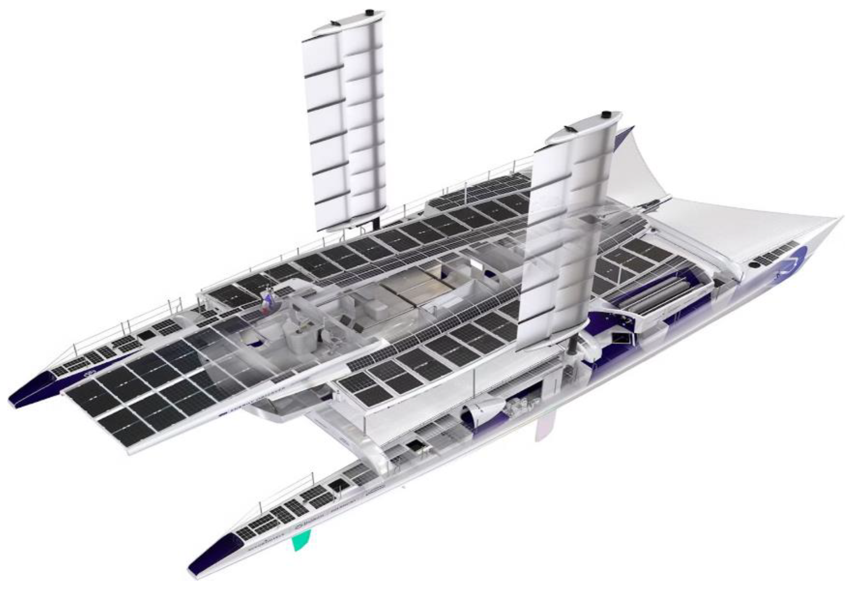
Figure 1. Hydrogen fuel cell yacht ‘Energy Observer’.
Energies 18 02526 g001
Figure 2. Hydrogen storage methods and types [22].
Energies 18 02526 g002
Figure 3. Advantages of liquid ammonia hydrogen storage over other methods [25].
Energies 18 02526 g003
Figure 4. Production and utilization routes of ammonia in the energy sector [26].
Energies 18 02526 g004
Figure 5. Steady vertical axisymmetric buoyant-free jet [46].
Energies 18 02526 g005
Figure 6. Schematic diagram of horizontal H2/air buoyant jet [47].
Energies 18 02526 g006
Figure 7. Virtual nozzle model proposed by Brich [48].
Energies 18 02526 g007
Figure 8. High-speed schlieren images of flame premixed hydrogen–air shape changes during propagation in a closed duct at various equivalence ratios [84].
Energies 18 02526 g008
Figure 9. Markstein length as the function of the equivalence ratio under different initial thermodynamic conditions [90].
Energies 18 02526 g009
Figure 10. Flame propagation process under different aspect ratios [100].
Energies 18 02526 g010
Figure 11. Detailed process of flame propagation: (a) φ = 0, (b) φ = 50%, and (c) φ = 100% [106].
Energies 18 02526 g011
Figure 12. Flame structure under different obstacle conditions [110].
Energies 18 02526 g012
Figure 13. Pressure response process of a hydrogen gas cloud explosion in the space of a hydrogenation station [118].
Energies 18 02526 g013
Figure 14. Schematic illustration of representative materials for chemiresistive H2 sensors [131].
Energies 18 02526 g014
Figure 15. Schematic of the anodic aluminum oxide nanowell–Pd nanostructure [140].
Energies 18 02526 g015
Figure 16. Multifunctional graphene sensors for H2 detection. (a) Gas detection schematics of the graphene sensors. (b) Atomic force microscopic image of a graphene channel covered with Pd nanoparticles. (c) Schematic diagram of the interaction between graphene and Pd nanoparticles [151].
Energies 18 02526 g016
Figure 17. Structure of a FBG hydrogen sensor: (1) fiber core, (2) fiber cladding, (3) polyimide layer, (4) titanium layer, and (5) palladium layer [163].
Energies 18 02526 g017
Figure 18. Image preprocessing (taking 76% of the initial concentration schlieren image as an example) [168].
Energies 18 02526 g018
Figure 19. Pattern of the laser beam passing through a hydrogen jet at different outlet pressures [171].
Energies 18 02526 g019
Figure 20. Distribution of the four stages of the deflagration-to-detonation transition process [219].
Energies 18 02526 g020
Figure 21. Iso-surfaces of the flame kernel taken after one eddy turnover time colored with the local equivalence ratio. Significant deviation from the global equivalence ratio can be seen from this image [222].
Energies 18 02526 g021
Disclaimer/Publisher’s Note: The statements, opinions and data contained in all publications are solely those of the individual author(s) and contributor(s) and not of MDPI and/or the editor(s). MDPI and/or the editor(s) disclaim responsibility for any injury to people or property resulting from any ideas, methods, instructions or products referred to in the content.