Article

Molten-Salt-Based Thermal Storage for Thermal Power Unit Plant Peaking

1
Institute of Thermal Science and Technology, Shandong University, Jinan 250061, China
2
Logistics Support Department, Shandong University, Jinan 250061, China
3
Anhui Special Equipment Inspection Institute, 45 Dalian Road, Hefei 230051, China
*
Authors to whom correspondence should be addressed.
Energies 2025, 18(10), 2522; https://doi.org/10.3390/en18102522
Submission received: 12 March 2025 / Revised: 22 April 2025 / Accepted: 29 April 2025 / Published: 13 May 2025

Abstract

As the integration of renewable energy sources continues to increase, thermal power units are increasingly required to enhance their operational flexibility to accommodate grid fluctuations. However, frequent load variations in conventional thermal power plants result in decreased efficiency, accelerated equipment wear, and high operational costs. In this context, molten-salt thermal energy storage (TES) has emerged as a promising solution due to its high specific heat capacity and thermal stability. By enabling the storage of surplus energy and its regulated release during peak demand periods, molten salt TES contributes to improved grid stability, reduced start-up frequency, and minimized operational disturbances. This study employs comprehensive thermodynamic simulations to investigate three representative schemes for heat storage and release. The results indicate that the dual steam extraction configuration (Scheme 3) offers the highest thermal storage capacity and peak-load regulation potential, albeit at the cost of increased heat consumption. Conversely, the single steam extraction configurations (Scheme 1 and 2) demonstrate improved thermal efficiency and reduced system complexity. Furthermore, Scheme 3, which involves extracting feedwater from the condenser outlet, provides enhanced operational flexibility but necessitates a higher initial investment. These findings offer critical insights into the optimal integration of molten-salt thermal-storage systems with conventional thermal power units. The outcomes not only highlight the trade-offs among different design strategies but also support the broader objective of enhancing the efficiency and adaptability of thermal power generation in a renewable-dominated energy landscape.

1. Introduction

As the global energy transition accelerates, the power sector faces both unprecedented challenges and opportunities. Fossil fuel-based power generation, particularly in thermal power plants, remains a vital component of the global electricity supply [1]. However, the rapid growth of renewable energy sources has introduced fluctuations and intermittency, creating significant challenges for grid stability. To address these issues, thermal power units must enhance their flexibility to effectively manage peak loads and respond swiftly to demand variations. Traditional peaking methods, however, increase the frequency of start-ups and shutdowns, leading to greater operational fluctuations, accelerated equipment wear, reduced efficiency, and higher costs. Therefore, the development of advanced energy storage and regulation technologies is critical for improving the reliability and economic viability of power systems. Molten-salt thermal storage has garnered significant attention as an efficient energy storage solution due to its high thermal capacity, superior heat transfer properties, and cost-effectiveness. This technology enables the storage of excess thermal energy, which can be released during peak demand periods, thereby stabilizing the power output, reducing the start-up and shutdown cycles, and enhancing the overall energy utilization. Its integration has the potential to redefine the role of thermal power units in future energy markets by improving their adaptability, efficiency, and grid stability.
Molten-Salt Thermal Storage Shows Significant Advantages in Medium- and High-Temperature Thermal Energy Storage [2,3]. Nitrate molten salts have been the main object of study because of their good thermal stability; however, their heat capacity is low, and the study was extended to chloride and fluoride molten salt materials [4,5,6]. The corrosion resistance and thermal properties can be further improved by optimizing the composition of the molten salt and by adding antioxidants [7]. Studies have shown that molten-salt thermal storage can significantly reduce the start-up and shutdown frequency of thermal power units and lower operating costs [8,9,10]. In addition, the integration of molten-salt thermal storage in multi-energy systems has significant economic and technological advantages [11,12]. Klasing et al. demonstrated the long-term cost-effectiveness of a molten-salt thermal storage system in a load fluctuation region through system modeling and economic analysis [13]. Despite the high initial cost, the potential benefits of highly volatile power markets make them an important direction for future energy storage technologies. Although previous research has laid the foundation for the development and application of molten-salt heat storage systems, some problems remain unsolved. The combination of thermal power units and molten-salt energy storage is an effective way to increase the flexibility of the units and improve the efficiency of the entire process cycle. However, few studies have been conducted on the operating conditions of thermal power units coupled with molten-salt energy storage, and the safety assurance of dual-tank systems requires further practical research. The feasibility of extracting reheated or superheated steam to heat molten salt has been demonstrated; however, the criteria for the exact amount of steam to be extracted are not yet clear, and the negative impact on the thermal power system as a whole needs to be further studied in a comparative manner. The long-term stability of molten salts and material corrosion have not yet been fully resolved [7,14]. Especially under high-temperature operating conditions, the corrosion of vessel materials and the chemical stability of molten salts significantly impact the system’s life, limiting its large-scale application. Existing research has focused on laboratory testing and theoretical modeling but lacks validation for real thermal power plant environments [15,16]. There are still many challenges in heat loss control and storage efficiency optimization in engineering applications. Although several studies have demonstrated the economic feasibility of molten-salt thermal storage under specific conditions, its high initial investment and operational complexity [13] make it an obstacle to its diffusion. The balance between technological advancement and economic cost requires further study.
This research in this paper aims to explore the feasibility and optimized design method of molten-salt heat storage technology in response to the problems of insufficient flexibility, equipment wear, and inefficiency in thermal power unit peaking. Through an in-depth analysis of the material properties, system integration, and economy of molten-salt heat storage systems, this study provides theoretical support and technical guidance for their practical application in thermal power plants. The significance of this study is to enhance the operational efficiency and reliability of molten-salt thermal storage systems by improving the materials and design, verifying the potential benefits of this technology in the power market, providing solutions for the economic operation of thermal power units, and support the further integration of renewable energy sources, contributing to energy transition and emission reduction targets.
For various thermal energy extraction points, three heat storage and heat release schemes are designed in this paper, aiming at flexibility requirements, peak performance optimization, and thermal economy trade-offs based on thermal power units under different operating conditions. Among the thermal storage schemes, Schemes 1 and 2 provide thermal energy by extracting the main steam and reheating steam, respectively, which simplifies the system structure and is suitable for schemes with medium flexibility requirements and high economic priority. Scheme 3 jointly extracts the main steam and reheat steam, which makes full use of the high-quality thermal energy of the two types of steam to significantly increase the thermal storage capacity and peak shifting depth, which is suitable for high flexibility requirements. In the heat release scheme, Scheme 1 and Scheme 2 extract feed water from the outlet of the deaerator to meet different load regulation requirements with better economy and adaptability. Scheme 3 significantly improves the heat transfer capacity and heat release by extracting low-temperature feed water from the outlet of the condenser to realize the maximum flexibility of peak shifting, which is applicable to working conditions with large load fluctuations. Through the design of these three schemes, system complexity, economy, and operational flexibility are taken into account, providing a comprehensive solution for the coupling of thermal power units with molten-salt thermal storage systems under different demands. Molten-salt storage system offers substantial advantages in accommodating variable renewable energy sources such as wind and solar power. Its ability to absorb excess energy during periods of high renewable generation and discharge it during times of low generation or high demand mitigates the inherent intermittency and volatility of renewables. This not only reduces the curtailment of renewable energy but also contributes to improved grid stability and facilitates complementary multi-energy operations. Consequently, the integration of molten salt systems into thermal power plants provides a promising pathway toward a more flexible, efficient, and renewable-friendly energy system.

2. Retrofit Program for Thermal Unit Coupled Molten-Salt Thermal Storage System

2.1. Thermal Power Unit Modeling

As shown in Figure 1, the Subcritical 330 MW thermal power unit contains a boiler, turbine, and power generation system. The exhaust gases from the high-pressure cylinder (HPT) are sent back to the boiler for reheating, after which they flow through the intermediate-pressure cylinder (IPT) and low-pressure cylinder (LPT). The heat recovery system consists of three high-pressure heaters (HPHS), four low-pressure heaters (LPHS), and a deaerator (DEA). The condensate is pumped into the low-pressure heater (LPHS) and deaerator to remove oxygen. Feedwater is then pumped into the High-Pressure Heater System (HPHS) to absorb heat from steam discharged from the High-Pressure Turbine (HPT) and Intermediate Pressure Turbine (IPT). Finally, the high-pressure, high-temperature feedwater re-enters the boiler to generate the main steam.
In this study, thermodynamic simulations of six integrated thermal power-molten-salt thermal storage systems were performed to calculate the parameters of the turbine at various thermodynamic states and evaluate the thermal efficiency of these integrated systems. The critical parameters of the thermal units at 100% THA under the rated operating conditions are listed in Table 1. The simulation assumptions used to simplify the system model during the simulation are as follows:
(1) Turbine shaft seals and valve stem leakages are not considered.
(2) Heat and leakage losses from equipment and piping are not considered.

2.2. Model Verification

A thermodynamic model of the thermal power unit was developed using EBSILON Professional software 13. The key input parameters, including the mass flow rate, temperature, and pressure of the main steam, as well as the reheat steam temperature and condenser backpressure, were specified based on the actual design conditions corresponding to various operational loads. Table 2 presents a comparison between the simulated results and original design data for three representative operating conditions (100% THA, 50% THA, and 40% THA). The relative error between the simulated and design values of the major operating parameters, such as the turbine output, steam flow rate, and thermal efficiency, was calculated to evaluate the accuracy of the model. The maximum relative deviation was found to be less than 2%, thereby demonstrating the high fidelity of the simulation model and confirming its reliability for further performance analyses.

2.3. Molten-Salt Heat Storage System

Molten-salt storage tanks are mainly categorized into single-tank and double-tank systems. Single-tank molten-salt energy storage systems are simple in structure and low in cost; however, they have the problem of lower heat storage efficiency due to the slanting temperature layer. The double-tank system contains cold and hot tanks, which avoids the problem of a slanting temperature layer by separating the cold and hot molten salts and circulating the heat exchange in the double tanks, and the technical risk is also relatively low. Therefore, a dual-tank system is selected for this study.
The thermal power unit model analyzed in this study operates with a main steam temperature of 537 °C and a reheat steam temperature of 537 °C. As shown in Table 3, from the perspective of physical properties, solar salt exhibits the highest melting point among the compared candidates, along with a relatively high density, specific heat capacity, and relatively low viscosity, making it advantageous for thermal storage applications. In terms of chemical stability, solar salt is also more favorable than Hetic salt, as the latter is prone to oxidation and decomposition. Although the introduction of an inert gas atmosphere is a common strategy for mitigating this issue, such an approach inevitably increases system complexity and operational costs. Furthermore, the price of Hetic salt is approximately 15% higher than that of solar salt, mainly due to the higher cost of its components, such as KNO3 and nitrites. These combined factors contribute to the relatively lower commercial maturity of Hetic salt compared to that of solar salt. Therefore, this study selects high-temperature-resistant solar salt (a eutectic mixture of 60% NaNO3 and 40% KNO3) as the thermal storage medium. It offers a high operating temperature of up to 565 °C, making it suitable for integration with the heat storage and peak-shaving operations of the thermal power unit. During off-peak load periods, steam from the combined-cycle thermal power unit transfers its thermal energy to the molten salt via a heat exchanger, which is referred to as the charging phase of the molten-salt thermal storage system. Conversely, during peak demand periods, the stored thermal energy is released to support power generation, which is known as the discharging phase. The integration scheme of a molten-salt thermal storage system with a thermal power unit significantly influences its thermal storage capacity, operational flexibility, and overall energy efficiency. Accordingly, the objective of this paper is to identify an optimal coupling configuration by evaluating the performance and efficiency of a thermal power unit before and after its integration with a molten-salt thermal storage system.
In this study, the fundamental design parameters of the heat exchanger, including the heat transfer area, heat transfer coefficient, and flow channel structure—exert a significant impact on the accuracy of the simulation results and overall system performance. Firstly, the heat transfer coefficient is a critical factor that governs the rate of thermal energy exchange. A higher coefficient enhances the heat transfer rate, thereby improving the overall thermal efficiency of the system. Secondly, the geometric structure of the heat exchanger influences the internal flow dynamics and heat transfer behavior, which in turn affects the residence time and temperature distribution of the molten salt within the exchanger. Additionally, the size of the heat transfer area directly determines its heat transfer capacity. An undersized area may result in insufficient thermal exchange, compromising system performance, while an oversized design can lead to unnecessary capital investment and increased operational costs. Therefore, the optimal design of an integrated heat exchanger requires a balanced and comprehensive consideration of these parameters to ensure both technical reliability and economic feasibility. The selected design parameters adopted in this study are summarized in Table 4 to substantiate the validity and rationality of the simulation outcomes.

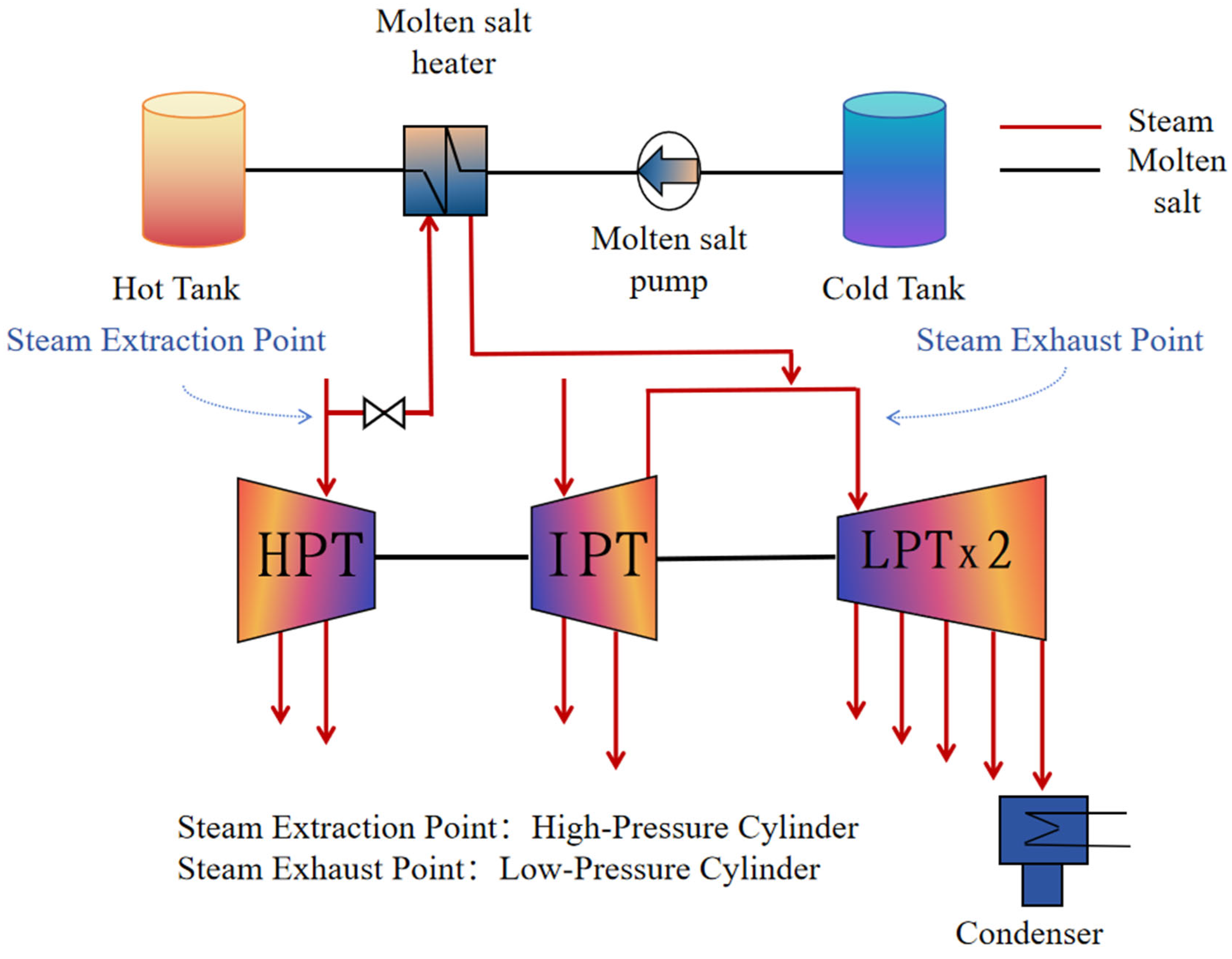
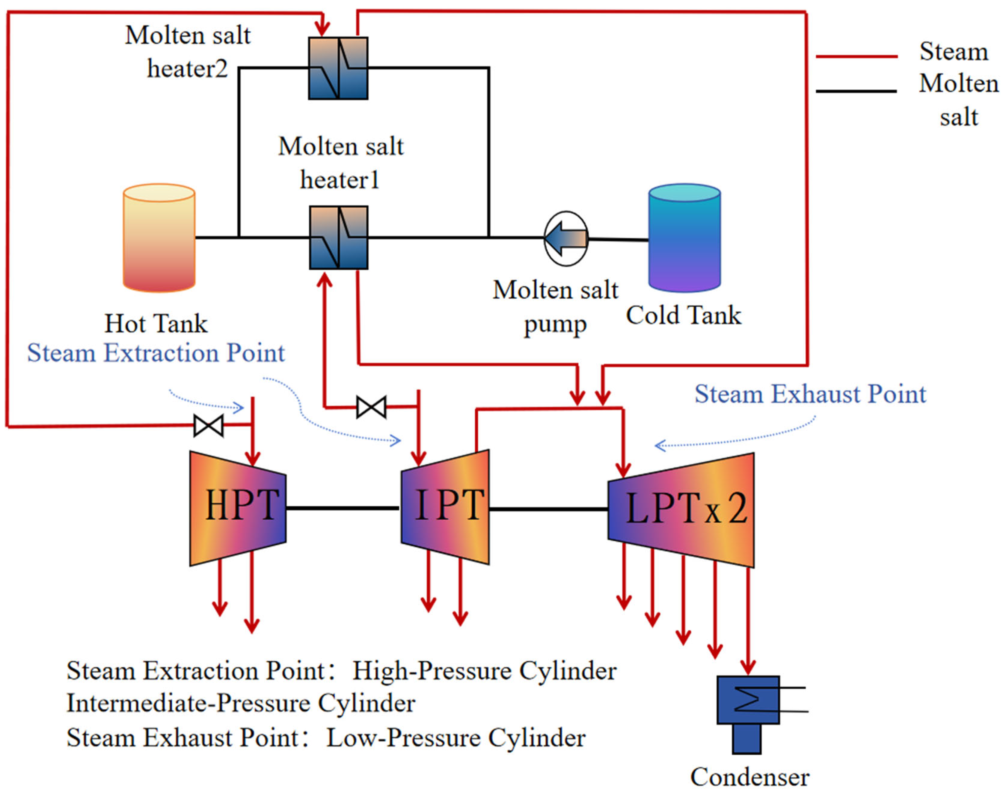
2.4. Thermal Storage

Currently, there are two main methods of applying molten-salt energy storage technology in thermal power units: one is to extract steam to heat the molten salt, and the other is to heat the molten salt using electricity. The extraction of steam for energy storage involves extracting high-temperature steam from a turbine system and using this steam to heat low-temperature molten salts, thereby transferring thermal energy to the molten salts and storing it in high-temperature molten salts. This approach requires determining the optimal extraction point and its associated parameters. The low-temperature molten salt is heated using an electric heater, which converts electrical energy into thermal energy and stores it in the high-temperature molten salt. This method is relatively simple because it uses electrical energy directly to heat molten salt. However, the economics of electrically heating molten salt are poor compared to those of vapor extraction for energy storage.
Molten salt is provided with thermal energy at the energy storage stage by extracting the main steam, reheating steam, and combining the heating of the main and reheating steam using three heat storage methods. At the same time, considering the stability of the turbine during low-load operation and the need for deep peaking, the extraction of main steam is limited to no more than 20% in order to prevent the reheater temperature from being too high; in order to adapt to the changes in the axial thrust of the turbine and the stress of the final stage blades, the extraction of reheat steam is controlled to no more than 30%.
As shown in Figure 2, Scheme 1 is heated by the main steam, and the molten salt delivered by the cold salt pump participates in the heat exchange. After the heat exchange of the main steam, it enters the low-pressure cylinder together with the medium-pressure cylinder exhaust steam to do work. The molten salt is first pumped from the cold tank by the cold salt pump, then heated by heat exchange with the extracted steam in the molten salt heat exchanger, and finally pumped into the hot tank for storage. The heat-exchanged steam is returned to the low-pressure cylinder to perform work.
As shown in Figure 3, Scheme 2 involves reheated steam heating, and the heat storage process is similar to that of Scheme 1. The reheat steam is selected to exchange heat with the molten salt, and the extraction point is selected at the inlet of the medium-pressure cylinder.
As shown in Figure 4, Scheme 3, in the heat storage process, the main steam is extracted to be used to heat a part of the molten salt, while the other part of the molten salt is heated by the reheated steam. These two portions of molten salt are then mixed and stored in the hot tank, and the main steam and reheated steam, after heat exchange, enter the low-pressure cylinder together with the medium-pressure cylinder exhaust steam to perform work.

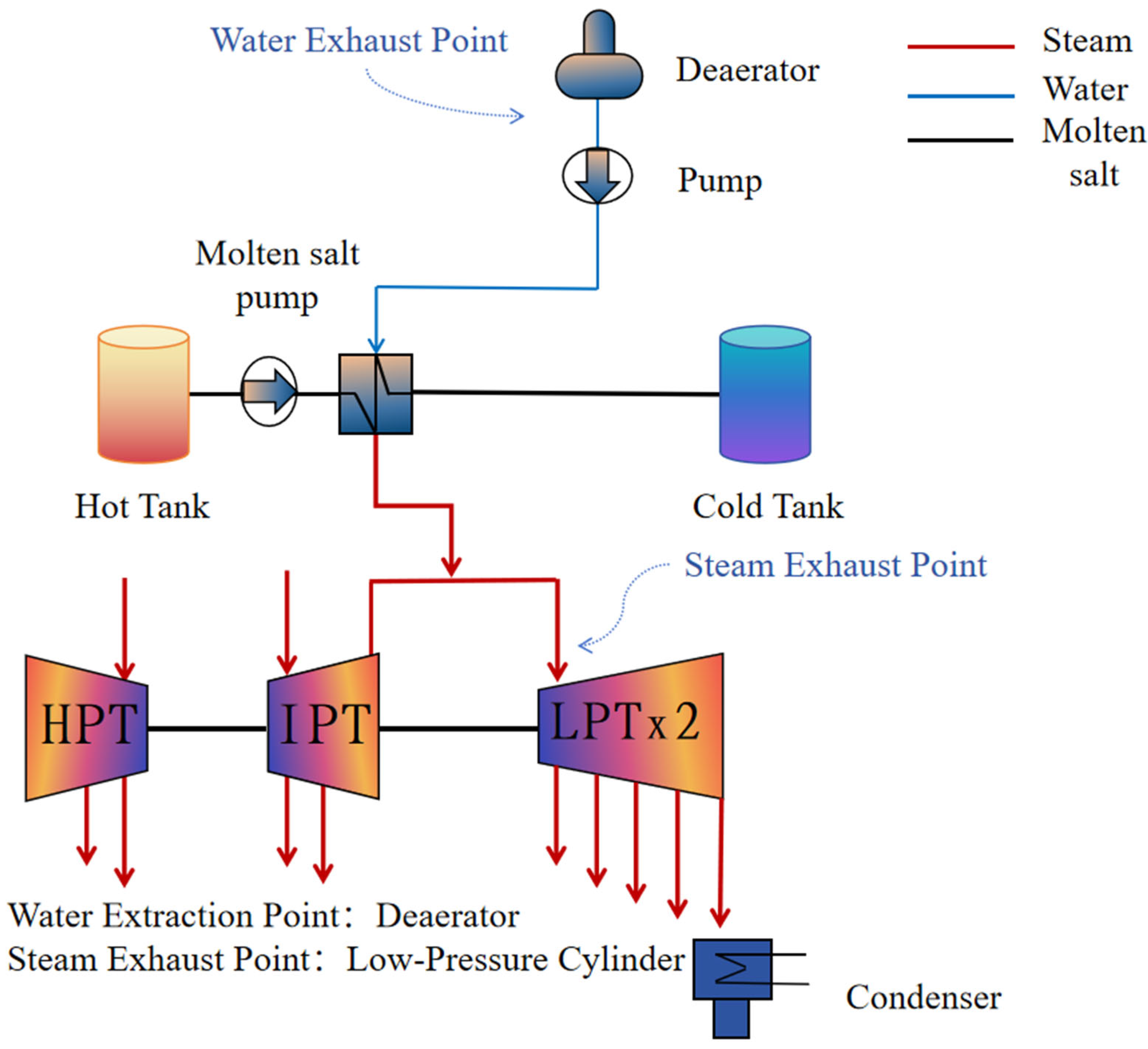
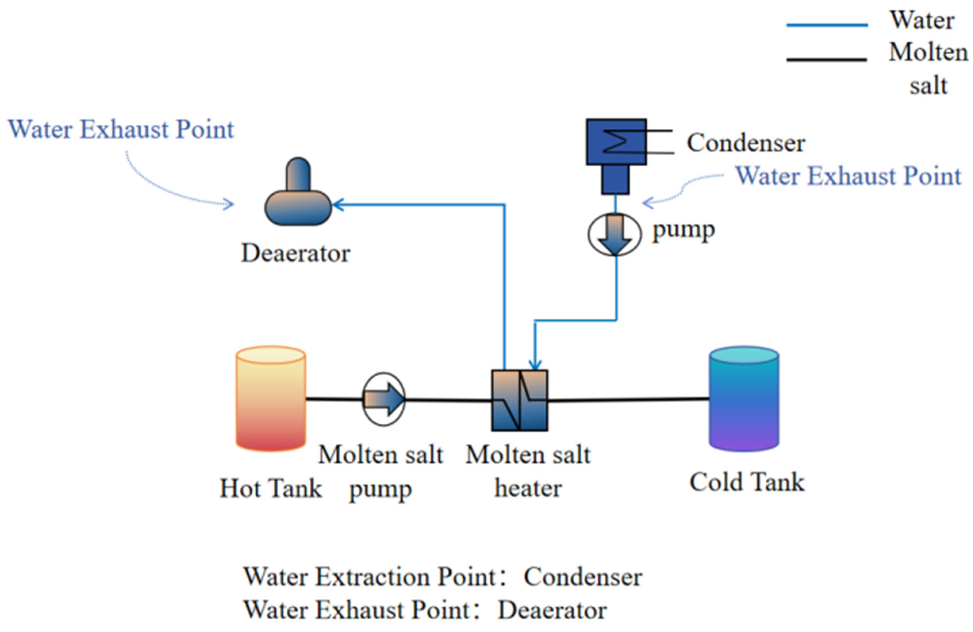
2.5. Exothermic Process

As shown in Figure 5, when heat is released in Scheme 1, feed water is first drawn from the outlet of the deaerator, which is then used to absorb the heat stored in the molten salt. The molten salt is at a high temperature when heat is stored, and when it comes into contact with subcritical water, the heat is transferred from the molten salt to the water. The feedwater is heated and enters the boiler, and by heating a portion of the feedwater, the turbine’s steam draw is reduced, resulting in an increase in power generation.
As shown in Figure 6, Scheme 2 changes the discharge point of feedwater on the basis of Scheme 1, and after the feedwater passes through the molten salt heat exchanger, the generated steam has the parameter conditions suitable for entering the steam low-pressure cylinder to work, and together with the medium-pressure cylinder exhaust steam, it enters the low-pressure cylinder to do work.
As shown in Figure 7, Scheme 3 can reduce the amount of steam extraction required by the turbine by extracting the feedwater from the outlet of the condenser and heating it with the molten-salt energy storage system; the feedwater, after heat exchange, enters the deaerator.

2.6. Evaluation Indicators

(1) Peak adjustment capacity and depth when coupling system heat storage: an important indicator of the flexibility of generating units and load adjustment ability in the power system, especially in response to load fluctuations or new energy access, plays a key role.
Δ P 1 = P e P 1 ; ψ 1 = Δ P 1 P e × 100 %
P1 is the output power of the coupled system when storing heat, Pe is the output power of the unit under rated conditions, Δ P1, ψ 1 are the peaking capacity and peaking depth of the coupled system during heat storage, respectively;
(2) Peaking capacity and depth of coupled systems when exothermic:
Δ P 2 = P 2 P 0 ; ψ 2 = Δ P 2 P e × 100 %
P2 is the output power when the coupled system is exothermic; Pe is the output power of the unit under rated conditions; Δ P2, ψ 2 are the peaking capacity and the peaking depth of the coupled system during heat release, respectively;
(3) The individual components are denoted as follows:
E es   E eg   + E ed   = W out   W in  
Ees, Eeg, and Eed are the effective energy supply, gain, and loss, respectively. Win and Wout are the power input and output, respectively.
(4) Heat consumption rate of thermal power units: The efficiency of the generating unit in converting fuel energy into electrical energy is an important indicator for evaluating the energy utilization efficiency of power generation equipment.
E 1 = ( h 2 h 1 ) + ( h 4 h 3 ) w
h 1 , h 2 , h 3 and h 4 feedwater enthalpy, main steam enthalpy, desuperheating water enthalpy, and reheat steam enthalpy, respectively. w is the electrical energy generated by the unit.
(5) Steam consumption rate of thermal power units: This reflects the amount of steam consumed per unit of electrical energy output and is commonly used to assess the efficiency of steam energy utilization of a generating unit.
E 2 = m w
m is the flow of steam consumed by the turbine in the process of generating electricity.

2.7. Capacity Analysis of Molten-Salt Thermal Storage Systems

330 MW thermal unit coupled to a molten-salt thermal storage system set for 1 h of peaking operation, the required stored electrical energy is:
E e = P · t = 330   M W × 1   h = 330   M W h
Considering that the turbine thermoelectric conversion efficiency is about η = 40%, and the heat energy required is
Q = E e η = 330 0.4 = 825   M W h = 2.97 × 10 9  KJ
A typical solar molten salt (60% NaNO3 + 40% KNO3) is used as the heat storage medium, taking its specific heat capacity c = 1.5 kJ/(kg·K), and the operating temperature difference ΔT = 290 K. Then, the mass of molten salt required is:
m = Q c · T = 2.97 × 10 9 1.5 × 290 = 6830 t
If the density of molten salt ρ = 1899 kg/m3, then the required volume of the heat storage tank is:
V = m ρ = 6.83 × 10 6 1899 = 3596   m 3
In summary, under the design condition of a 1 h peak duration, the coupled molten-salt thermal storage system needs to be equipped with about 6830 tons of molten salt and 3596 m3 of thermal storage volume to realize the thermo-electrolytic coupling operation of the 330 MW thermal power unit.

3. Result and Discussion

3.1. Thermal Storage Process Analysis

In the combined-cycle system of a molten-salt-coupled thermal power unit, there is a strong link between the heat storage capacity, peaking capacity, and peaking depth in different combined-cycle modes. These performance indicators are not only influenced by the design of the molten salt system but also directly depend on the safety constraints of the turbine operation, in particular, the minimum requirements for the pumping mass flow (which usually needs to be maintained at least 10% of the full load flow) in order to ensure a safe turbine operation.
As shown in Figure 8, the heat storage capacity of Scheme 3 (combined extraction of main steam and reheat steam) reaches 15.17 MW, which is significantly higher than that of Scheme 1 (7.14 MW) and Scheme 2 (about 10 MW). This result is attributed to the fact that Scheme 3 is able to effectively improve the heat transfer efficiency of the molten-salt heat exchanger while enhancing the heat capacity of the molten salt when combining two types of high-quality steam. This result validates the unique advantages of the combined steam extraction approach for exploiting the thermal potential of the turbine. In contrast, Scheme 1 utilizes only a single reheat steam and has a lower heat storage capacity. Scheme 2 partially compensates for the deficiency by extracting the main steam; however, due to the fact that the efficiency of the two-phase heat transfer after main steam extraction is slightly lower than that of the single-phase heat transfer (as in the case of the reheat steam heat exchanger), the heat storage capacity is still lower than that of Scheme 3.
In terms of peaking performance, Scheme 3 also performs well, with a maximum peaking depth (close to 20%), while Scheme 1 and 2 have relatively low peaking depths. This phenomenon reflects the flexibility and efficiency of the combined pumping strategy in coping with load fluctuations and demonstrates the strong correlation between thermal storage capacity and peaking depth. The advantage of Scheme 3 is that the flexibility is improved while still maintaining a high thermal efficiency, which is important for the current highly volatile new energy power system.
The results of this study show an improvement in the performance metrics compared with existing studies. For example, the results in Ref. [17] show that molten-salt thermal storage systems based on a single steam extraction method typically have a thermal storage capacity in the range of 6–10 MW, which is consistent with the results of Scheme 1 and 2 in this paper, but significantly lower than the performance of Scheme 3. This may stem from insufficient consideration of turbine operational safety in existing studies or underutilization of the energy utilization enhancement brought about by the combined pumping strategy. Ref. [3] proposes a similar joint vapor extraction method, but its heat storage capacity and peak shifting depth are slightly lower than the results of Scheme 3 in this paper. The difference may arise from the difference in heat exchanger design and optimization of steam extraction parameters, where the molten-salt heat exchanger in Ref. [3] uses a single high-efficiency heat exchanger, while the study in this paper pays more attention to the joint heat exchanger design, which optimizes the total system efficiency by reasonably configuring the heat exchanger flow of main steam and reheat steam. In this study, a more in-depth optimization of the extraction pressure and temperature has been carried out to further increase the heat transfer capacity and, at the same time reduce the safety risk of the turbine. In addition, Ref. [18] points out that the quality of turbine extraction is the key to heat storage efficiency, especially at high-temperature and high-pressure steam, where the heat transfer capacity is significantly increased. This conclusion is highly consistent with the performance of Scheme 3 in this paper. However, Ref. [18] did not deeply analyze the correlation between the steam extraction mode and the peaking depth, while the study in this paper further verifies the significant impact of the extraction strategy on peaking flexibility.
The results of Scheme 3 in this paper outperform most of the existing studies in terms of heat storage and peaking performance, which is mainly attributed to the advantages of the combined steam extraction strategy, parameter optimization, and constraint considerations. In particular, by combining the extraction of the main steam and reheated steam, this paper fully utilizes the thermal potential of different steam conditions and improves the overall efficiency of the molten-salt heat exchanger. This design has been less systematically explored in previous studies. In this study, while optimizing the heat storage system, the safe operational constraints of the turbine are strictly considered to ensure feasibility in practical engineering. This approach makes the results closer to industrial applications, while operational constraints are not fully considered in some studies [19], resulting in some deviations between theoretical results and practical applications.
Exergy analysis serves as an effective diagnostic tool for evaluating energy utilization and identifying inefficiencies in thermoelectric coupling systems integrated with molten-salt heat storage. This method enables the quantification of exergy losses and highlights the system components and processes in which irreversibility is most pronounced. Figure 9 illustrates the variations in the exergy efficiencies of the key components, including the high-pressure cylinder (HPC), intermediate-pressure cylinder (IPC), low-pressure cylinder (LPC), high-pressure heater (HPH), low-pressure heater (LPH), and deaerator, before and after coupling the thermal unit with the molten-salt thermal storage system. In the original configuration, the high-pressure cylinder exhibits the highest exergy efficiency, reaching up to 97%. Following the integration of the heat storage system, all the schemes experienced a reduction in exergy efficiency to varying extents. Notably, Scheme 1 shows the most significant decline, with the HPC efficiency decreasing to 96.3%. This drop is likely attributed to the reduction in the high-pressure steam quality resulting from the partial steam extraction for molten-salt heating, which introduces greater irreversible losses. In contrast, Scheme 3 exhibits the smallest reduction in the HPC exergy efficiency, declining to 96.8%. This improved performance is primarily due to the combined steam extraction strategy, which distributes the heat load more evenly and mitigates the loss of thermal economy. These results demonstrate the importance of coupling strategy optimization for minimizing exergy destruction and maintaining system efficiency. The exergy-use efficiency of the high-pressure cylinder decreased significantly in Scheme 1, while it was mitigated in Scheme 3. Similar results were also found in the study by Li et al. [20]. They pointed out that the degradation of steam quality in high-pressure cylinders is the main source of irreversible losses in heat storage systems. Compared with Xu et al. [21], the efficiency of the high-pressure cylinder in this study decreased less, which may be attributed to the optimized design of the location of the steam extraction point and amount of steam extraction. The change in the exergy efficiency of the medium-pressure cylinder was small, with a difference of less than 0.3% between the schemes, indicating that its sensitivity to steam extraction was relatively low. This may be due to the fact that the operating parameters of the medium-pressure cylinder reside between the high- and low-pressure ones, which can partially mitigate the effects of steam quality degradation. Zhang et al. [22] and Wei et al. [23] have shown that the low-pressure cylinder is susceptible to the positive effects of steam quality changes due to its lower operating parameters. However, these studies only focused on a single steam extraction strategy, and the maximum efficiency improvement of the low-pressure cylinder was about 93%. The combined steam extraction strategy in this study significantly improved the low-pressure cylinder efficiency (to 94%), demonstrating the advantages of multiple steam extraction schemes in the optimization of low-pressure cylinder operation.
The exergy efficiency of the low-pressure cylinder under Option 3 is significantly improved to 94%, which is about 2 percentage points higher than that of the original unit and significantly better than those of the other two options. This indicates that the operating characteristics of the low-pressure cylinder under low-parameter steam are more suitable for optimizing the operation by combined steam extraction to achieve thermal efficiency improvement. The exergy-use efficiencies of the high-pressure and low-pressure heaters (HPHS and LPHS) are close to the level of the original unit in Scheme 3 and slightly higher than those in Schemes 1 and 2. This indicates that the combined steam extraction mode effectively reduces the irreversible losses of the heaters while satisfying the requirements of the heat storage system.
The differential causes include different steam extraction modes and the control of the heat source and heat sink temperature differences. Zhang et al. [22] used a single steam extraction strategy, which only optimized the operational performance of the high-pressure or low-pressure cylinders, while the combined steam extraction strategy in this study performed better in balancing the efficiencies of the high-pressure and low-pressure cylinders by rationally distributing the steam heat load. Wei et al. [23] emphasized the effect of the heat source and the temperature difference of the heat sink on the heat storage system performance but did not further analyze the oblique temperature layer effect. In this study, the effect of the oblique thermosphere was reduced by the optimization of the heat storage system, resulting in a higher heat utilization efficiency in the low-pressure cylinder operation.
Figure 10 shows the trends of the heat and steam consumption rates under the three thermal storage schemes before and after coupling the thermal unit with the molten-salt thermal storage system. The results show that the heat and steam consumption rates of the three schemes are higher than those of the original unit, with Scheme 3 having the highest heat and steam consumption rates of 9741.1 kJ/kWh and 3.42 kg/kWh, respectively. This suggests that the combined extraction of the main and reheat steam, although significantly increasing the thermal storage capacity, results in a decrease in the overall performance due to the additional system complexity and energy losses. In contrast, Schemes 1 (main steam extraction only) and 2 (reheat steam extraction only) have lower heat and steam consumption rates, respectively, reflecting the efficiency of energy conversion in the single steam extraction mode. Scheme 2, in particular, shows a significant reduction in the steam consumption rate by optimizing the utilization path of the reheated steam, which indicates a more advantageous economic and thermodynamic performance while meeting the flexibility requirements.
Comparing the results of this paper with a case study of the thermal storage retrofit of a coal-exergy power plant mentioned in the literature [24], which states that its optimized single steam extraction strategy resulted in an improvement of about 7% in the heat consumption rate, while the heat consumption rate improvement of Scheme 2 of this paper is about 6.5%, the results of both have a high degree of consistency. This suggests that optimizing a single steam path is an effective strategy. However, a study based on a molten-salt thermal storage system in the literature [25] shows that a system with dual steam co-extraction (similar to Scheme 3 of this paper) has a heat consumption rate improvement of about 9.8%, while Scheme 3 of this paper has a heat consumption rate improvement of nearly 11.3%. This difference may stem from the differences in equipment load design and the degree of steam path optimization. In addition, the literature [26] indicates that the performance of heat exchange equipment in molten-salt heat storage systems significantly affects the overall efficiency, whereas in this paper, there may be room for optimization in the heat exchanger design, resulting in greater entropy gain losses.

3.2. Exothermic Process Analysis

Figure 11 presents the relationship between heat release, peaking capacity, and peaking depth for the three heat release schemes. The results show that Scheme 3 (heat release by extracting feedwater from the condenser outlet) has the highest heat release capacity of about 37 MW, while the peaking depth reaches 15%, which is significantly higher than those of Schemes 1 (26 MW, 11% peaking depth) and 2 (22 MW, 8% peaking depth). This indicates that Scheme 3 is able to significantly reduce the generation power during the load trough period, providing maximum load regulation flexibility to the grid. Scheme 3 is outstanding in terms of heat release, and its high heat release is attributed to the extraction of low-temperature feedwater from the condenser outlet, which significantly reduces the temperature difference at the outlet of the molten-salt heat exchanger and improves heat transfer capacity. In contrast, the heat release of Scheme 1 and Scheme 2 is lower, and the difference is 11 MW and 15 MW, respectively, which indicates that Scheme 3 is more capable of fully utilizing the low-temperature heat source.
Compared with the study in the literature [27], the heat release of the condenser outlet feedwater extraction strategy, similar to Scheme 3 in that study is 35 MW, and the peaking depth is 14%. The heat release and peaking depth of Scheme 3 in this paper are slightly higher than those in this study, probably due to the further optimization of the heat transfer path of the molten-salt heat storage system in the design of this paper, which reduces the heat energy loss. The heat release of Scheme 1 in the literature [28] study is 28 MW, which is slightly higher than the 26 MW in this paper, while the peak shifting depth is consistently 11%. In addition, a similar study of Scheme 2 in the literature [29] shows a heat release of 24 MW and a peak shifting depth of 9%, both slightly higher than the results of this paper, and the differences may arise from the differences in the design parameters of the molten-salt heat exchanger and the circulation efficiency.
In this paper, Scheme 3 extracts low-temperature feedwater through the condenser outlet, which significantly reduces the temperature difference at the heat exchanger outlet and improves the heat transfer capacity. However, compared with the literature [27], there may be room for further optimization of its equipment, such as more efficient heat transfer materials or structural design, which may explain the slightly higher heat release in Scheme 3 than that in the literature results. In Scheme 2, the temperature at the extraction point is higher than that in Scheme 3, and the heat utilization efficiency is relatively low, resulting in a lower heat release and peaking depth than similar schemes in the literature [29]. While Option 3 is superior in terms of heat release and peaking depth, the system equipment requirements are significantly higher, resulting in higher energy losses in the molten salt cycle. The literature [28] indicates that the additional load on the molten-salt circulation pumps and heat exchange equipment affects the overall efficiency, which may be a side effect of the higher equipment complexity of Option 3. The literature [29] emphasizes the critical impact of the feedwater extraction path on the efficiency of molten-salt heat storage systems. In this study, the path designs of Option 1 and Option 2 may be more simplified, but they have advantages in terms of economics and equipment complexity. Therefore, they are more suitable for operational schemes with moderate flexibility requirements.
Figure 12 demonstrates the trends in the heat and vapor consumption rates of the three exothermic schemes under different pumping capacities (from 50 t/h to 300 t/h). The heat consumption rate and vapor consumption rate are important indicators of the performance of molten-salt thermal storage and power generation systems, and they directly affect the overall efficiency of the system. The heat consumption rate (kJ/kWh) indicates the amount of heat consumed per unit of power generated, and a higher heat consumption rate indicates greater heat loss, which reduces the energy utilization efficiency of the system. The steam consumption rate (kg/kWh) reflects the amount of steam consumed per unit of electricity generated. A higher steam consumption rate usually indicates a less efficient energy conversion during steam turbine expansion, resulting in additional energy consumption in the system. The results show that the heat and vapor consumption rates of all schemes gradually decrease with increasing pumping volume, which reflects the improvement in the operating efficiency of the molten-salt heat storage system. The heat and vapor consumption rates of Scheme 3 (condenser outlet pumping) decreased the most at high pumping capacities, reaching 8390 kJ/kWh and 2.85 kg/kWh, respectively, which were significantly better than those of Schemes 1 and 2. The heat consumption rate for Option 2 (deaerator outlet pumping followed by return to the low-pressure cylinder) is slightly higher than that of Option 1 at low pumping rates; however, the two converge as the pumping rate increases. This suggests that the thermal utilization efficiency of steam improves at high pumping rates for Scheme 2. In contrast, Scheme 1 (deaerator outlet pumping followed by return to the boiler) exhibits a lower thermal economy at high pumping rates, with heat and steam consumption rates of 8435 kJ/kWh and 3.05 kg/kWh, respectively.
The significant effect of pumping volume on the heat and steam consumption rates stems from three factors: heat exchange efficiency improvement, optimal utilization of steam quality, and control of irreversible losses. With an increase in the pumping volume, the heat exchange temperature difference between the feed water and molten salt decreases, which improves the heat utilization efficiency of the heat exchanger and reduces the system heat consumption rate. In particular, in Scheme 3, a lower heat consumption rate is exhibited due to the lowest water temperature at the condenser outlet, which maximizes the use of molten salt heat. The decrease in the steam consumption rate indicates a reduction in the amount of steam required per unit of electrical energy output. This trend is particularly noticeable in Scheme 3, indicating that this scheme optimizes the steam utilization path by reducing the dependence on high-quality steam and the need to pump the unit’s main steam. High pumping conditions reduce system throttling losses by more fully utilizing the heat from molten-salt storage, thus having a positive effect on the reduction in heat and steam consumption rates.

4. Conclusions

It should be noted that due to certain functional limitations of the simulation software used in this study, it is not yet possible to fully integrate and evaluate the energy consumption of the subsystems in the molten-salt cycle system to derive the overall efficiency of the whole system. The software mainly focuses on thermal and mobility performance analysis within the unit components. Therefore, this paper mainly focuses on the comparison of the heat storage and heat transfer performance of molten salt under different scenarios, and based on this, a qualitative discussion of the energy consumption characteristics is presented. Future research will attempt to use a more functional simulation platform or a self-built model for a more comprehensive analysis and evaluation of the overall system efficiency. In this study, we conducted a systematic analysis of three heat storage and release strategies within the context of integrating a molten-salt thermal energy storage system with thermal power units. The evaluation focused on the effects on the heat consumption rate, steam consumption rate, thermal discharge characteristics, and peak-shaving performance. Based on the simulation results, the following key conclusions are drawn:
A comparative analysis of the three thermal storage schemes indicates that Scheme 3, which involves the simultaneous extraction of the main steam and reheated steam, substantially enhances the thermal storage capacity. However, this improvement comes at the cost of increased heat consumption (9741.1 kJ/kWh) and steam consumption (3.42 kg/kWh), primarily due to the additional heat exchange pathways and the resulting equipment complexity. In contrast, the single steam extraction configurations (Schemes 1 and 2) exhibit superior thermal economies. Notably, Scheme 2 achieves a significant reduction in steam consumption by optimizing the reheat steam extraction pathway, highlighting its greater potential to strike a balance between energy efficiency and system design simplicity.
Scheme 3, which utilizes low-temperature feedwater extracted from the condenser outlet for heat release, achieves the highest heat release output (37 MW) and peak-shaving depth (15%), significantly outperforming the other schemes. These results demonstrate that the deep thermal utilization of low-temperature feedwater can effectively enhance the flexibility and regulation capacity of thermal storage systems. However, the improved peaking performance is accompanied by increased equipment requirements and greater heat losses, underscoring the necessity of balancing the regulation capability with the operational economics in practical applications.
In summary, although Scheme 3 demonstrates superior performance in terms of thermal storage and release capacity, its high system complexity and elevated heat dissipation rate constrain its applicability in scenarios in which economic efficiency is a primary concern. For operating conditions with moderate flexibility requirements, Schemes 1 and 2 offer greater potential for widespread application due to their favorable trade-off between economic viability and operational adaptability.
Looking ahead, further optimization efforts may be directed toward the following areas:
(1) Development of economically driven steam quality allocation strategies.
(2) Enhancement of heat exchanger design efficiency to minimize thermal losses; and
(3) The establishment of dynamic control models tailored to actual load profiles, thereby enabling more practical and efficient system designs for integrated thermal energy storage applications.

Author Contributions

Conceptualization, F.R. and X.R.; methodology, F.M. and H.Y.; software, L.X.; validation, H.L., L.X. and X.R.; formal analysis, F.M. and H.Y.; investigation, F.R.; resources, X.R.; data curation, F.R.; writing—original draft preparation, F.R.; writing—review and editing, H.L., L.X. and X.R.; visualization, L.X.; supervision, X.R.; project administration, L.X.; funding acquisition, X.R. All authors have read and agreed to the published version of the manuscript.

Funding

This research was funded by the Anhui Province Quality Infrastructure Standardization grant number 2023MKS19, and the Science and Technology Project of China Huaneng Group (HNKJ22-H24).

Data Availability Statement

The original contributions presented in the study are included in the article, further inquiries can be directed to the corresponding author.

Conflicts of Interest

The authors declare no conflict of interest.

References

  1. Liu, J.; Xu, M.; Guo, W.; Xi, W.; Liu, C.; Sunden, B. Flow and heat transfer mechanism of a regenerative cooling channel mounted with pin-fins using supercritical CO2 as coolant. Int. J. Therm. Sci. 2025, 208, 109425. [Google Scholar] [CrossRef]
  2. Roper, R.; Harkema, M.; Sabharwall, P.; Riddle, C.; Chisholm, B.; Day, B.; Marotta, P. Molten salt for advanced energy applications: A review. Ann. Nucl. Energy 2022, 169, 108924. [Google Scholar] [CrossRef]
  3. Rajagopalan, K.K.; Karimineghlani, P.; Zhu, X.; Shamberger, P.J.; Sukhishvili, S.A. Polymers in molten inorganic salt hydrate phase change materials: Solubility and gelation. J. Mater. Chem. A 2021, 9, 25892–25913. [Google Scholar] [CrossRef]
  4. Caraballo, A.; Galán-Casado, S.; Caballero, Á.; Serena, S. Molten Salts for Sensible Thermal Energy Storage: A Review and an Energy Performance Analysis. Energies 2021, 14, 1197. [Google Scholar] [CrossRef]
  5. Bonk, A.; Sau, S.; Uranga, N.; Hernaiz, M.; Bauer, T. Advanced heat transfer fluids for direct molten salt line-focusing CSP plants. Prog. Energy Combust. Sci. 2018, 67, 69–87. [Google Scholar] [CrossRef]
  6. Bellan, S.; Kodama, T.; Gokon, N.; Matsubara, K. A review on high-temperature thermochemical heat storage: Particle reactors and materials based on solid–gas reactions. WIREs Energy Environ. 2022, 11, e440. [Google Scholar] [CrossRef]
  7. Mallco, A.; Portillo, C.; Kogan, M.J.; Galleguillos, F.; Fernández, A.G. A Materials Screening Test of Corrosion Monitoring in LiNO3 Containing Molten Salts as a Thermal Energy Storage Material for CSP Plants. Appl. Sci. 2020, 10, 3160. [Google Scholar] [CrossRef]
  8. Denbow, C.; Le Brun, N.; Mac Dowell, N.; Shah, N.; Markides, C.N. The potential impact of Molten Salt Reactors on the UK electricity grid. J. Clean. Prod. 2020, 276, 122873. [Google Scholar] [CrossRef]
  9. Miao, L.; Liu, M.; Zhang, K.; Zhao, Y.; Yan, J. Energy, exergy, and economic analyses on coal-fired power plants integrated with the power-to-heat thermal energy storage system. Energy 2023, 284, 129236. [Google Scholar] [CrossRef]
  10. Patel, S.; Mallapragada, D.S.; Ganesan, K.; Stoner, R. Repurposing coal plants into thermal energy storage—A techno-economic assessment in the Indian context. Environ. Res. Infrastruct. Sustain. 2024, 4, 035007. [Google Scholar] [CrossRef]
  11. Bartolucci, L.; Cordiner, S.; Mulone, V.; Pasquale, S.; Santarelli, M. Hybrid renewable energy systems: Impact of thermal storage on systems optimal design and performance. In AIP Conference Proceedings; AIP Publishing LLC: Melville, NY, USA, 2019; Volume 2191, p. 020016. [Google Scholar]
  12. Ma, Z.; Wang, X.; Davenport, P.; Gifford, J.; Martinek, J. Economic Analysis of an Electric Thermal Energy Storage System Using Solid Particles for Grid Electricity Storage. In Proceedings of the ASME 2021 15th International Conference on Energy Sustainability Collocated with the ASME 2021 Heat Transfer Summer Conference, Online, 16–18 June 2021. [Google Scholar]
  13. Klasing, F.; Odenthal, C.; Trost, B.; Hirsch, T.; Bauer, T. Techno-Economic Assessment for Large Scale Thermocline Filler TES Systems in a Molten Salt Parabolic Trough Plant. In Proceedings of the AIP Conference Proceedings, Santiago, Chile, 26–29 September 2017. [Google Scholar]
  14. Ibrahim, A.; Peng, H.; Riaz, A.; Abdul Basit, M.; Rashid, U.; Basit, A. Molten salts in the light of corrosion mitigation strategies and embedded with nanoparticles to enhance the thermophysical properties for CSP plants. Sol. Energy Mater. Sol. Cells 2021, 219, 110768. [Google Scholar] [CrossRef]
  15. Zhang, Y. Applicability of Thermal Energy Storage in Future District Heating System-Design Methodologies and Performance Evaluations; Chalmers Tekniska Hogskola: Göteborg, Sweden, 2021. [Google Scholar]
  16. Palacios, A.; Navarro, M.E.; Barreneche, C.; Ding, Y. Hybrid 3 in 1 thermal energy storage system—Outlook for a novel storage strategy. Appl. Energy 2020, 274, 115024. [Google Scholar] [CrossRef]
  17. Prasad, J.S.; Muthukumar, P.; Desai, F.; Basu, D.N.; Rahman, M.M. A critical review of high-temperature reversible thermochemical energy storage systems. Appl. Energy 2019, 254, 113733. [Google Scholar] [CrossRef]
  18. Yingling, J.A.; Schorne-Pinto, J.; Aziziha, M.; Ard, J.C.; Mofrad, A.M.; Christian, M.S.; Dixon, C.M.; Besmann, T.M. Thermodynamic measurements and assessments for LiCl-NaCl-KCl-UCl3 systems. J. Chem.Thermodyn. 2023, 179, 106974. [Google Scholar] [CrossRef]
  19. Xu, J.; Liu, W.; Wang, Z.; Ma, S.; Zhao, G.; Gu, Y. Comparative investigation on the thermodynamic performance of coal-fired power plant integrating with the molten salt thermal storage system. J. Energy Storage 2024, 89, 111738. [Google Scholar] [CrossRef]
  20. Li, B.; Cao, Y.; He, T.; Si, F. Thermodynamic analysis and operation strategy optimization of coupled molten salt energy storage system for coal-fired power plant. Appl. Therm. Eng. 2024, 236, 121702. [Google Scholar] [CrossRef]
  21. Liang, X.; Xu, T.; Feng, B.; Jiang, Z. Optimization of heat extraction strategies in fault-controlled hydro-geothermal reservoirs. Energy 2018, 164, 853–870. [Google Scholar] [CrossRef]
  22. Zhang, H.; Sun, L.; Zhao, H.; Zhang, X.; Xin, G. Thermodynamic analysis of the coal-fired combined heat and power units integrated with steam ejectors and thermal storage. J. Energy Storage 2024, 90, 111869. [Google Scholar] [CrossRef]
  23. Wei, S.; Liang, X.; Mohsin, T.; Wu, X.; Li, Y. A simplified dynamic model of integrated parabolic trough concentrating solar power plants: Modeling and validation. Appl. Therm. Eng. 2020, 169, 114982. [Google Scholar] [CrossRef]
  24. Pang, L.; Zhang, S.; Duan, L. Flexibility Improvement Study on the Double Reheat Power Generation Unit With a High Temperature Molten Salt Thermal Energy Storage. Proc. Chin. Soc. Electr. Eng. 2021, 41, 2682–2690. [Google Scholar]
  25. Cao, L.; Li, X.; Wang, D. A thermodynamic system of coal-fired power unit coupled S–CO2 energy-storage cycle. Energy 2022, 259, 125015. [Google Scholar] [CrossRef]
  26. Wang, A.; Liu, J.; Zhang, S.; Liu, M.; Yan, J. Steam generation system operation optimization in parabolic trough concentrating solar power plants under cloudy conditions. Appl. Energy 2020, 265, 114790. [Google Scholar] [CrossRef]
  27. Zhao, Y.; Liu, M.; Wang, C.; Wang, Z.; Chong, D.; Yan, J. Exergy analysis of the regulating measures of operational flexibility in supercritical coal-fired power plants during transient processes. Appl. Energy 2019, 253, 113487. [Google Scholar] [CrossRef]
  28. Ju, H.; Wang, Y.; Feng, Y.; Zheng, L. Numerical Study on Peak Shaving Performance of Combined Heat and Power Unit Assisted by Heating Storage in Long-Distance Pipelines Scheduled by Particle Swarm Optimization Method. Energies 2024, 17, 492. [Google Scholar] [CrossRef]
  29. Zhou, J.; Huang, D.; Zhou, L. Modeling and thermal economy analysis of the coupled system of compressed steam energy storage and Rankine cycle in thermal power plant. Energy 2024, 291, 130309. [Google Scholar] [CrossRef]
Figure 1. Model of 330 MW subcritical thermal power unit.
Energies 18 02522 g001
Figure 2. Scheme 1 Main steam heat storage.
Energies 18 02522 g002
Figure 3. Scheme 2 Reheat steam heat storage.
Energies 18 02522 g003
Figure 4. Scheme 3 Integrated heat storage.
Energies 18 02522 g004
Figure 5. Scheme 1 Molten salt heat boiler feed.
Energies 18 02522 g005
Figure 6. Scheme 2 low-pressure cylinder steam boosting.
Energies 18 02522 g006
Figure 7. Molten-salt heat-assisted deaeration feedwater system.
Energies 18 02522 g007
Figure 8. Relationship between heat storage, peaking capacity, and peaking depth for different coupling methods.
Energies 18 02522 g008
Figure 9. Comparison of the efficiencies of each component before and after coupling.
Energies 18 02522 g009
Figure 10. Comparison of heat consumption rate and vapor consumption rate before and after coupling.
Energies 18 02522 g010
Figure 11. Relationship between heat release, peaking capacity, and peaking depth for different coupling methods.
Energies 18 02522 g011
Figure 12. Relationship between the heat consumption rate and vapor consumption rate for different pumping volumes. ((a) Scheme 1, (b) Scheme 2, (c) Scheme 3).
Energies 18 02522 g012aEnergies 18 02522 g012b
Table 1. Critical parameters for thermal power units at 100% THA.
ParameterUnitvalue
RatingMW330
Main Steam Mass Flow Ratet/h1024
Main Steam PressureMPa16.67
Main Steam Temperature°C537
High-Pressure Cylinder Discharge PressureMPa3.556
Reheated Steam Mass Flow Ratet/h835.783
Reheated Steam PressureMPa3.2
Reheated steam temperature°C537
Back pressureMPa0.00539
Feed water temperature°C272.7
Heat consumption rateKj/Kwh7976
Gas consumption rateKg/Kwh3.03
Table 2. Simulation and design data for key parameters under three typical operating conditions. (100% THA, 50% THA and 40% THA).
Designed ValueSimulated ValueRelative Error/%
100%50%40%100%50%40%100%50%40%
Main Steam Pressure (MPa)16.679.267.4116.679.2877.47400.030.86
Main Steam Mass Flow Rate (t/h)1002.4486396.51002.4490.392391.83100.91.17
Reheated Steam Pressure (MPa)3.21.6061.3123.2491.6371.3281.51.91.2
Reheated Steam Mass Flow Rate (t/h)835.783421.835346.806851.287429.757350.2651.81.870.9
Generation capacity (MW)330165.018132326.157165.0181321.200
Table 3. Common physical properties of the three molten salts.
Chemical CompositionSolar SaltHetic SaltHetic XL Salt
NaNO3/%6077
KNO3/%405345
NaNO2/%0400
Ca(NO3)2/%0048
Melting point/°C220142120
Upper temperature limit/℃600535500
Intensity/(kg·m−3) (300 °C)189916401992
Stickiness/cp (300 °C)3.263.166.37
Thermal capacity/(J·kg−1·K−1) (300 °C)149515601447
Table 4. Heat exchanger basic parameters.
ParameterValue
Heat exchanger monotube length/m6
Single-tube outer diameter/mm25
Single-tube wall thickness/mm2.5
Inner diameter of the shell/m0.5
Single-tube thermal conductivity/W·(m·K)−117
Specific heat of a single tube/kJ·(kg·K)−1502
Single-tube density/kg·m−37500
L/D ratio12
Velocity/(m·s−1)2
Disclaimer/Publisher’s Note: The statements, opinions and data contained in all publications are solely those of the individual author(s) and contributor(s) and not of MDPI and/or the editor(s). MDPI and/or the editor(s) disclaim responsibility for any injury to people or property resulting from any ideas, methods, instructions or products referred to in the content.

