Review

Review of Electrochemical Systems for Grid Scale Power Generation and Conversion: Low- and High-Temperature Fuel Cells and Electrolysis Processes

1
Department of Electrical and Computer Engineering, Baylor University, Waco, TX 76798, USA
2
Department of Mechanical Engineering, Baylor University, Waco, TX 76798, USA
*
Author to whom correspondence should be addressed.
Energies 2025, 18(10), 2493; https://doi.org/10.3390/en18102493
Submission received: 24 March 2025 / Revised: 6 May 2025 / Accepted: 7 May 2025 / Published: 12 May 2025
(This article belongs to the Section B: Energy and Environment)

Abstract

:
This review paper presents an overview of fuel cell electrochemical systems that can be used for clean large-scale power generation and energy storage as global energy concerns regarding emissions and greenhouse gases escalate. The fundamental thermochemical and operational principles of fuel cell power generation and electrolyzer technologies are discussed with a focus on high-temperature solid oxide fuel cells (SOFCs) and solid oxide electrolysis cells (SOECs) that are best suited for grid scale energy generation. SOFCs and SOECs share similar promising characteristics and have the potential to revolutionize energy conversion and storage due to improved energy efficiency and reduced carbon emissions. Electrochemical and thermodynamic foundations are presented while exploring energy conversion mechanisms, electric parameters, and efficiency in comparison with conventional power generation systems. Methods of converting hydrocarbon fuels to chemicals that can serve as fuel cell fuels are also presented. Key fuel cell challenges are also discussed, including degradation, thermal cycling, and long-term stability. The latest advancements, including in materials selection research, design, and manufacturing methods, are also presented, as they are essential for unlocking the full potential of these technologies and achieving a sustainable, near zero-emission energy future.

1. Introduction

To maintain a comfortable quality of life in modern society, there is a never-ending need for reliable and sustainable energy. Almost everything experienced in our daily life is powered by electricity, including an increasing number of vehicles, which were traditionally powered by internal combustion engines. The US has approximately 291.1 million cars currently in operation on the road as of the second quarter of 2024 [1]. From 30 June 2023 to 30 June 2024, nearly 19 percent of new cars sold were either hybrid-powered (11%) or fully electric (8%) [1].
Energy resources can be classified into three main categories: hydrocarbon fuels, nuclear energy, and renewables (i.e., wind, solar, hydropower, geothermal, etc.) [2]. Among these three main categories, hydrocarbons are most widely used due to the broad legacy of existing infrastructure, resulting in ready accessibility for most of the population. However, they also have the potential to cause the most damage to the environment, including by polluting soil, water, marine life, and terrestrial ecosystems [3].
With increased public awareness, the desire to use alternative renewable energy has become more popular than ever. Research in different fields of renewable energy and recent advancements could resolve environmental issues, especially developments in electrochemical systems. Electrochemical energy conversion processes directly convert chemical energy into electrical energy which can be harvested during a chemical reaction, as opposed to the traditional use of a combination of combustion and a heat machine. There are many electrochemical energy sources available that could be harvested; however, galvanic energy (e.g., fuel cells), electrolytic energy (e.g., solid oxide electrolysis cells), and thermo-electrochemical cells are the most significant examples [4,5].
Fuel cells have the potential to complement and enhance intermittent renewable energy sources like solar and wind [6]. Unlike these renewables, which depend on weather conditions and the time of day, fuel cells provide a stable and continuous power supply [7]. They can be fueled by natural gas through existing pipeline infrastructure to homes or more extensive facilities, enabling greater penetration of distributed energy generated for increased system resilience [8]. They can also be powered by portable hydrogen refill tanks or stationed larger tanks, making them a versatile energy solution. If hydrogen is generated using renewable energy sources such as solar or wind, it effectively converts intermittent power generation into a reliable, on-demand energy source [9,10]. This approach enables the storage of surplus renewable energy as hydrogen [11,12]. Hydrogen can later be used in fuel cells to generate electricity when solar or wind power is unavailable [13]. By integrating fuel cells into residential, industrial, and transportation sectors, society can greatly decrease reliance on fossil fuels, contributing to a reduction in carbon emissions. Additionally, fuel cells offer high efficiency, quiet operation, and minimal environmental impact, making them an attractive alternative to conventional combustion-based power systems.
As society moves toward a carbon-neutral future, integrating solid oxide electrolysis cells (SOECs) into the energy system presents a promising solution. SOECs operate in the reverse mode of solid oxide fuel cells (SOFCs), utilizing electricity and heat to split water (H2O) and carbon dioxide (CO2) into hydrogen (H2) and carbon monoxide (CO). The resulting H2 and CO can then be fed into an SOFC, where they undergo electrochemical reactions to generate electricity efficiently. This closed-loop process creates a highly integrated and efficient energy cycle, enabling carbon recycling and reducing reliance on fossil fuels (see Figure 1) [14].
The ability of SOFCs and SOECs to integrate with existing energy infrastructure, combined with advancements in hydrogen storage and distribution, is paving the way for a more sustainable and resilient energy ecosystem [15,16,17]. The high temperature of operation enables the reforming of hydrocarbons to fuels, either internally in the fuel cell [18,19] or externally in a secondary system [20,21]. Generally, electrode reforming can lead to higher fuel utilization, but external fuel pre-reforming leads to a more compact system [22]. Further, because high-temperature fuel cells generate high-temperature heat as a byproduct, that heat can be supplied to a bottoming cycle, such as a microturbine or Rankine cycle, to further extract work from the fuel, thus improving efficiency [23,24,25,26]. By leveraging renewable energy sources to power SOECs, surplus electricity from solar, wind, and other renewables can be converted into hydrogen and syngas, providing a stable and dispatchable energy source. This approach not only enhances energy storage capabilities but also helps decarbonize industries such as power generation, transportation, and manufacturing. If hydrogen production fully transitions to renewable sources, fuel cells and electrolysis technologies could play a crucial role in achieving a near zero-emission future [27,28]. Their deployment can ensure clean, efficient, and uninterrupted energy for homes, businesses, and transportation networks, ultimately contributing to a sustainable and carbon-free global energy system.

Contributions of This Review Paper

This paper comprehensively reviews the fundamental principles of electrochemical energy conversion systems, including low-temperature systems, with a focus on high-temperature systems suitable for grid scale energy generation, material advancements, operational performance, manufacturing processes, and emerging applications. This review also discusses electrochemical and thermodynamic foundations, exploring their energy conversion mechanisms, reaction kinetics, electric parameters, and efficiency. A significant focus of this paper is on material selection and performance metrics, especially on electrocatalytic activity, ionic and electronic conductivity, and thermal stability. Recent advancements in anode, cathode, and electrolyte materials are also discussed. Degradation mechanisms, including thermal cycling effects and long-term operational stability, are also presented. Additionally, this review investigates electrical parameters such as activation, ohmic, and concentration losses, which directly impact the power density and fuel utilization efficiency of SOFC systems.

2. Thermodynamics and Electrical Parameters of High-Temperature Solid Electrolyte Electrochemical Systems

2.1. Reversible Efficiency of an Electrochemical Energy Conversion System

For a chemical system, ∆rHo, which represents the available chemical energy in a chemical process when all species are at standard conditions (a system in which the partial pressure of each gas species is at po = 105 Pa = 1 bar [29]), is calculated as the difference between the enthalpy of the reactants and of the products,
r H o = p r o d u c t s f H o r e a c t a n t s f H o
and, similarly, the available work as the difference in Gibbs’ free energy of the reactants and products, r G o .
r G o = p r o d u c t s f G o r e a c t a n t s f G o
Generally, the standard state is reported at a temperature of T = 20 °C = 293.15 K [30], such is the case for data reported by the US NIST, but care must be taken with specific sources.
The maximal efficiency of energy extraction is therefore the ratio between the extracted work and the available energy, which may also be expressed in terms of extracted work ( r G ˙ o ) and of supplied energy ( r G ˙ o ):
η = r G ˙ o r H ˙ o = r G o r H o = r H o T r S o r H o = 1 T r S o r H o = 1 T r S ˙ o r H ˙ o
Additionally, the term T r S o represents the chemical energy present in the reactants that is lost as heat in the reaction.
When not under these standard conditions, e.g., when the partial pressure of the species is not the standard pressure, such is usually the case for operating fuel cells, temperature-specific values for the reactant species enthalpy and entropy must be used, as well as modifying the resulting term by employing the accurate partial pressure.
To adjust the values for temperature other than the tabulated values (i.e., when values for the enthalpy and entropy of formation for the reaction components are not known), estimations must be made with high reliability using the Shomate equation using the data archived at the US NIST [31].
H o H 298.15 o   [ k J / m o l ] = A t + B t 2 2 + C t 3 3 + D t 4 4 E t + F H
S o   [ J / m o l . K ] = A ln t + B t + C t 2 2 + D t 3 3 E 2 t 2 + G
where t = T   [ K ] / 1000 .
These values can be used to calculate the temperature-corrected r H T o and r G T o . The tabulated Shomate parameters for the H2/O2 combustion reaction for the temperature range of 298 K to 1000 K are given in Table 1 below.
When the partial pressures of the reactants and products are not under standard conditions, then one must further adjust the Gibbs’ free energy of reaction by including the reaction quotient term Q.
r G T = r G T o + R T ln Q
where Q r is the reaction quotient expressed as
Q r = i p i ν i j r j ν j
In Electrochemical Engineering terms, the energy required for a process is presented in terms of moving a mole of test charges across an electrical potential. In this case, the available work is given by
r G T o = z F E T o E T o = r G T o z F
As before, if not under standard conditions, the effect of the temperature and concentration of the reactants and products must be taken into account. In this case, the equation becomes the Nernst equation
E T = E T o R T z F ln Q r

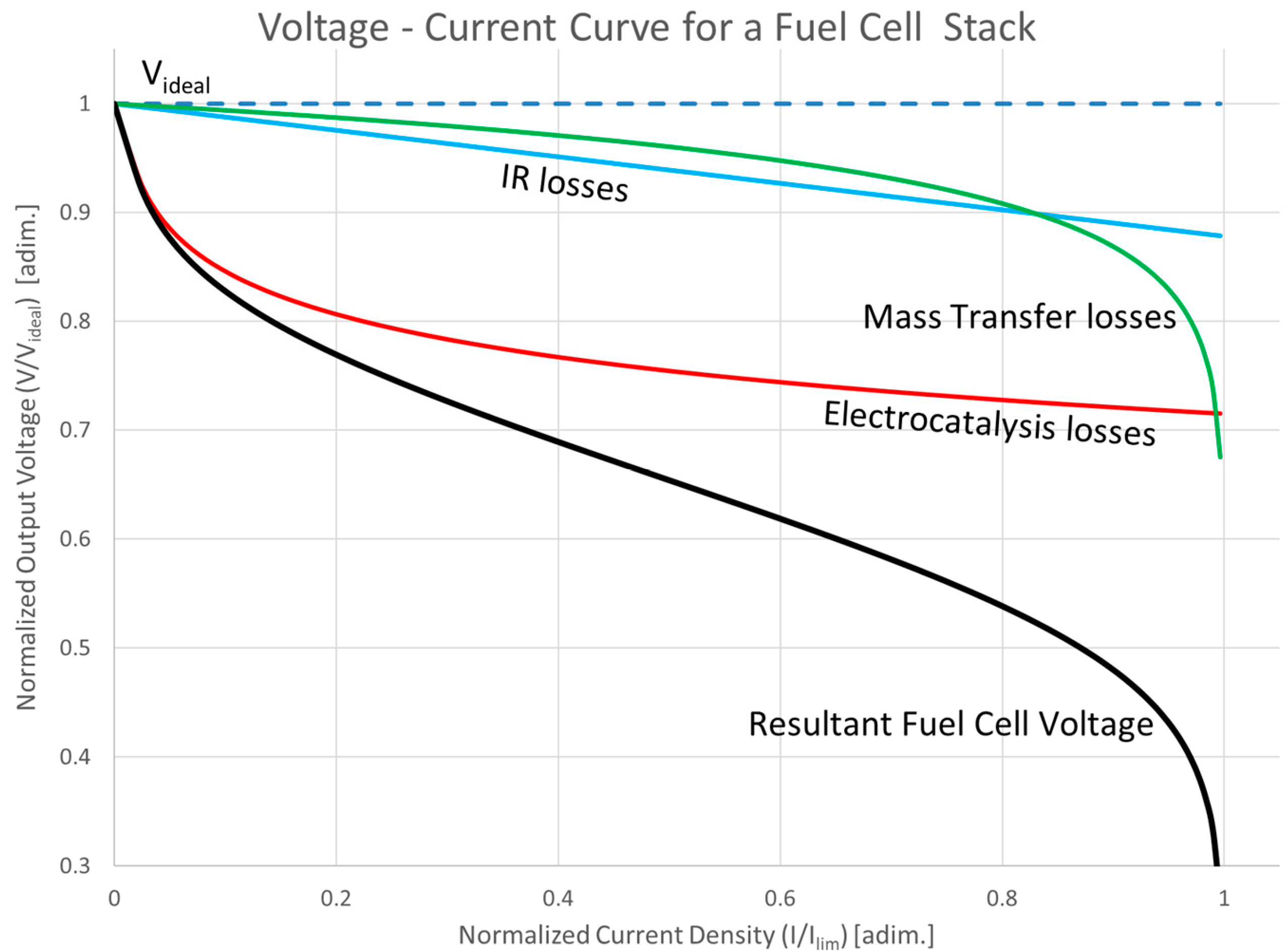
2.2. Efficiency Degrading Issues

The overall effects of losses in the fuel cell is demonstrated in Figure 5, which will be detailed in the following subsections.

2.2.1. Electrocatalytic Activation Losses

When electrochemical systems operate with current flow greater than zero, whether as galvanic or electrolytic systems, energy must be supplied to overcome the activation energy barrier. Activation losses arise from the energy required to initiate the electrochemical reactions at the electrodes. These losses depend on the electrode material, microstructure, temperature, and reactant concentrations.
In an electrochemical system, the required activation energy appears as a loss in the system and is referred to as the “activation overpotential”, labeled here as V a c t . For sufficiently large rates of electrochemical reaction (i.e., currents significantly different from zero), V a c t can be modeled using the Tafel equation [32,33,34,35]:
V a c t = R T α z F l n ( i i 0 )
where
  • V a c t = activation potential (V);
  • R = universal gas constant (8.314 J/mol · K);
  • T = absolute temperature (K);
  • α = charge transfer coefficient;
  • z = number of electrons involved in the reaction;
  • F = Faraday’s constant (96,487 C/mol);
  • i = current density (A/cm2);
  • i 0 = exchange current density (A/cm2).
The exchange current density j 0 is a critical parameter representing the intrinsic activity of the electrode material. Larger j 0 values indicate more efficient electrocatalysis with lower activation losses. Note that while a separate activation overpotential exists at each electrode (i.e., the H2 and the O2 electrode), these will be combined into one overall loss in this paper.

2.2.2. Ohmic (IR) Losses

A second source of losses is the electromigration of ions through the electrolyte, and electron flow in the electrodes and interconnections. These losses are referred to as IR losses or ohmic losses, and cause a voltage drop proportional to the current, expressed as [36,37]
V o h m = i · R o h m
where
  • V o h m = ohmic overpotential;
  • i = current density (A/cm2);
  • R o h m = total ohmic resistance (Ω·cm2).
Minimizing ohmic losses involves selecting materials with high ionic and electronic conductivities and optimizing the fuel cell’s structural design to reduce resistive pathways.

2.2.3. Mass Transport Losses

Finally, as reaction rate increases further, mass transfer effects decrease the local concentration of reactants and increase the concentration of products in the reaction zone, further decreasing the available ∆rGT that is converted to electrical work. The transport losses have been well described previously [38,39], and become significant at high current densities. In a conventional reaction engineering problem, this would be presented in terms of the polarization equation, and is represented in electrochemical terms. The resulting concentration overpotential can be approximated by [40,41]
V m a s s = R T n F l n ( c * c )
where
  • V m a s s = concentration overpotential (V);
  • R = universal gas constant (8.314 J/mol·K);
  • T = absolute temperature (K);
  • n = number of electrons involved in the reaction;
  • F = Faraday’s constant (96,487 C/mol);
  • c * = bulk concentration of reactants;
  • c = concentration of reactants at the electrode surface.
Effective fuel cell design addresses mass transport losses by optimizing flow field patterns, electrode porosity, and reactant flow rates to ensure adequate supply and removal processes.
A list of specific kinetic factors that contribute to the specific amplitude and shape of the Tafel curve for a system is beyond the scope of this paper, as these features depend on several factors, including the rate of electron transfer, diffusion coefficients, and specific morphological features of the electrodes implementation.

2.2.4. Overall Fuel Cell Voltage

The overall performance of a fuel cell can be represented by the polarization curve, which plots the cell voltage V against current density i. The cell voltage is given by [42,43]
V c e l l = E T V a c t V o h m V m a s s
where
  • V c e l l = cell voltage;
  • E T = reversible open circuit voltage at the Temperature used;
  • V a c t = total activation overpotential;
  • V o h m = total ohmic overpotential;
  • V m a s s = total concentration overpotential.
Figure 5. Effect of losses in the fuel cell [44].
Energies 18 02493 g005

2.2.5. Fuel Utilization Ratio

The remaining key loss is due to the incomplete utilization of the fuel. Because a fuel cell is a flow-through device and the oxidation products accumulate on the fuel side, the concentration of the fuel in the fuel stream continuously decreases. At some point, the remaining concentration of the fuel is sufficiently low that increasing the fuel cell surface to convert the remaining fuel to energy is no longer useful, usually from an economic standpoint. The remaining unused fuel is then vented from the fuel cell in the tail gas.
U f = n ˙ f , s u p p l i e d n ˙ f , e x h a u s t n ˙ f , s u p p l i e d = n ˙ f , r e a c t e d n ˙ f , s u p p l i e d
where n ˙ f , s u p p l i e d represents the flowrate of fuel supplied to the fuel cell and n ˙ f , e x h a u s t represents the fuel still present in the tailgas [45].
A fuel utilization ratio smaller than 1 does not impact the cell voltage; rather, it represents energy that is not extracted from the fuel. Therefore, it represents a fraction of the work available that was not extracted.
For an electrochemical process, the power flow can be calculated as
P = V c e l l · i
and the current i is proportional to the rate of reaction in the fuel cell ( i = z · n ˙ f , r e a c t e d ).
Therefore, in this case, the overall efficiency of the fuel cell is the ratio between the electrochemical power output and the input energy flow,
η = r G ˙ T ,   r e a c t e d r H ˙ T , s u p p l i e d o = r G T . n ˙ f , r e a c t e d r H T o . n ˙ f , s u p p l i e d = r G T r H T o U f = r G T z F r H T o z F U f = V c e l l r H T o z F U f
where all the quantities shown have the same meaning as described above.
Fuel utilization ranges from 0.8 to 0.95 are reported in the literature. In some combined SOFC designs, the tail gas is combusted in a gas turbine to extract the remaining heat and chemical energy using a heat machine, and a further Rankine bottoming cycle can be added for a “triple stack” system to further improve the efficiency [46].

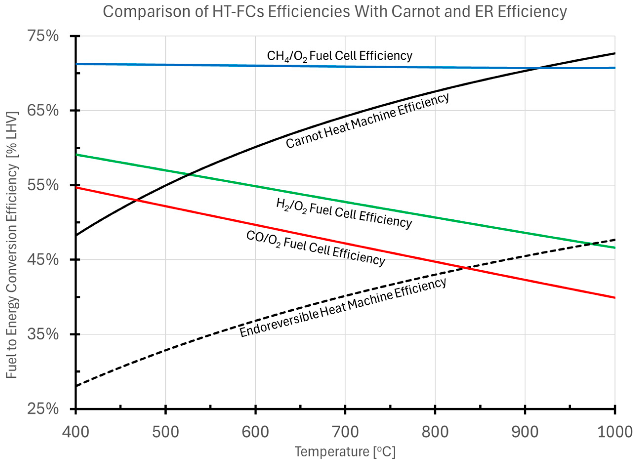
2.3. Fuel Cell Efficiency Compared to That of Heat Machines

Because the goal of a fuel cell is to convert chemical energy to electrical energy, it is worth comparing the performance of a fuel cell, as derived above, with that of a heat machine. In order to discuss this properly, the fundamental thermodynamics of an electrochemical energy conversion system must first be examined. The traditional comparison between a fuel cell, with all the losses described in Section 3.2.1, Section 3.2.2 and Section 3.2.3, is compared to the Carnot efficiency of a heat machine, given as
η C a r n o t = 1 T c o l d T h o t
where T h o t is the temperature of the “hot reservoir” from which heat is extracted, and T c o l d is the temperature at which heat is rejected to the environment. Although Carnot efficiency plays an important role in the history of thermodynamics, having led to the Clausius formulation of entropy, it should be noted that reaching this ideal efficiency requires the process to occur at time scales that are infinitely slow. As a result, the thermal machine delivers zero power [47,48].
A better comparison for the development of practical energy generation is the efficiency of a conceptual machine operating at finite, non-zero power. The limiting efficiency of such a heat machine that involves heat transfer and finite time work conversion is the Endoreversible Efficiency [49,50]. This is calculated as
η E R = 1 T c o l d T h o t
where the terms have the same meaning as above. The Endoreversible Efficiency estimate has been shown as a good estimate of large-scale Rankine power systems [50], and, similarly, the calculated efficiency at maximum power for a Brayton Cyle (e.g., a natural gas fired turbine) has the upper bound of the Endoreversible Efficiency [51].
Figure 2 presents a comparison between the efficiency of a solid oxide fuel cell operating at 80% of idealized thermodynamic efficiency and utilizing 90% of the supplied fuel, against the calculated efficiency of heat machines rejecting heat at a temperature of 50 °C, including the idealized Carnot efficiency and the Endoreversible Efficiency.
This illustrates the potential gains in electrical energy generation that may be derived from the use of fuel cells as opposed to traditional combustion-based energy conversion processes. The reason why the efficiency of the conceptual direct CH4 fuel cell remains high is that the process really embodies two reactions that happen in tandem:
C H 4 + 3 C O 2 4 C O + 2 H 2 O
4 C O + 2 O 2 4 C O 2
Since the first reaction is endothermic, and the second reaction is exothermic, a balance between the two reactions occurs that essentially keeps the heat generation at a minimum. This is illustrated in Figure 3. As discussed above, the hydrocarbon fuel may be reformed internally on the fuel cell electrode, or, alternatively, externally in an additional piece of equipment.
The general trend for the calculated r H T o , T r S T o , and r G T o for the hydrogen–oxygen combustion reaction based on the Shomate parameters in Table 2 is shown in Figure 4. The range of temperatures used by low-temperature electrochemical systems (e.g., PEM and alkaline fuel cells and electrolyzers), Intermediate Temperature SOECs, and high-temperature solid oxide electrochemical systems is highlighted. The fraction of the available energy ( r H T o ) that must be supplied as electrical work to an electrolyzer ( r G T o ) is shown in green, and the fraction of the energy that is supplied as heat in an electrolyzer ( T r S T o ) is shown in red. The case for the CO2 reduction by electrolysis follows similar trends, where the energy supplied as heat is a greater proportion of the total, and therefore a figure illustrating that case was not included, for brevity.
The desire to operate the hydrogen–oxygen (or hydrogen–air) fuel cell at the lowest possible temperature, then, is obvious, since this wastes the least energy in the fuel as heat. Conversely, the desire to operate an electrolyzer at the highest possible temperature is also self-evident, since this decreases the fraction of energy that must be supplied as electrical work, with the energy supplied as heat, which is much less expensive than electrical work. Additionally, the reaction is endothermic, which allows external waste heat (e.g., industrial waste heat, nuclear waste heat, or solar heat) to assist in driving the reaction which could further reduce electricity consumption [52]. In addition to water electrolysis, SOECs can perform co-electrolysis of water and carbon dioxide (CO2) to produce syngas (a mixture of H2 and CO), which serves as a precursor for synthetic fuels and chemicals [53].

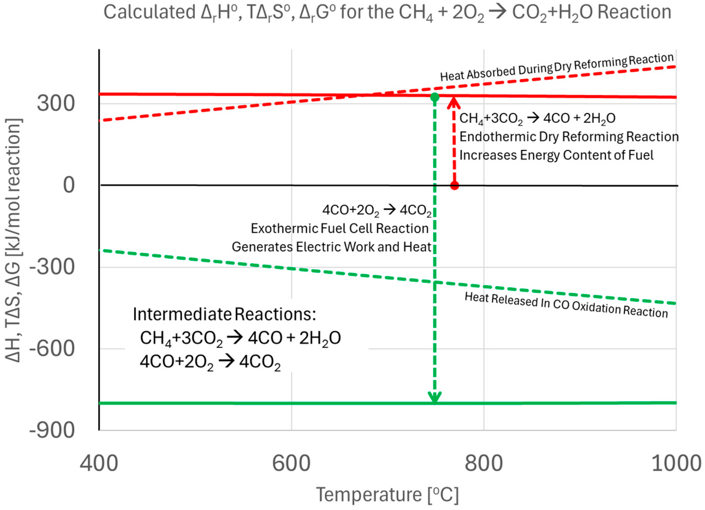
2.4. Direct Use of Hydrocarbon Fuels in Fuel Cells

2.4.1. Conventional Reforming Methods

In order to enable direct use of hydrocarbon fuels in fuel cells, the fuel must be converted to a form usable by the fuel cell. In the following discussion, for simplicity, only methane will be used as an example hydrocarbon fuel, but the reactions may be generalized for other hydrocarbons such as propane, ethanol, and gasoline, providing flexibility in feedstock selection.
Three conventional methods of converting methane to mixtures of carbon monoxide and hydrogen, also known as syngas, are generally discussed: steam reforming, frequently referred to as SMR, for steam methane reforming, when the hydrocarbon being reformed is methane; dry reforming; and autothermal reforming, according to Equations (21)–(23).
Steam   reforming :   C H 4 + H 2 O 4 C O + 3 H 2     r H 1100 K o = 226   k J
Dry   reforming :   C H 4 + C O 2 2 C O + H 2     r H 1100 K o = 260   k J
Partial   oxidation   reforming :   C H 4 + 1 2 O 2 C O + H 2   r H 1100 K o = 21.6   k J
The reaction enthalpies shown are for the reactions as written, calculated using the Shomate parameters from Table 1, for a temperature of T = 827 °C = 1100 K and at pressure of 1 bar (i.e., r H 1100 K o ).
For SMR and DR (see Equations (21) and (22)), steam at temperatures in the range shown below is used. For high-temperature fuel cells, this extra step is unnecessary, as these can directly use CO as fuel, decreasing the required equipment costs.
Water   gas   shift :   C O + H 2 O C O 2 + H 2     r H 1100 K o = 33.9   k J
To further ensure high hydrogen purity, a separation of any remaining CO and CO2 can be effected, whether by membrane, pressure swing, or solvent-based processes, and if it is desired that CO concentrations be below the ppm range, for example, because CO is a catalyst poison in low-temperature fuel cells, then a methanation step (i.e., CO + 3H2 → CH4 + H2O, merely the steam reforming reaction of Equation (21) in reverse) over a nickel-based catalyst can be employed. The inclusion of any of these processes further increases the cost of the hydrogen fuel, and should be avoided if possible, depending on the degree of purity required from the fuel cell process.
It should be noted that these reforming reactions do generate carbon emissions—the production of 1 kg H2 also generates approx. 10 kg CO2 [54]. Although CO2 sequestration and storage for SMR has been demonstrated, the extra process equipment and energy overhead required for capturing and sequestering the CO2 significantly increases cost of H2 produced by SMR: in North America, the cost of SMR H2 is in the range of 1.2~1.5 USD/kg-H2 at a natural gas price of ~USD 3 per MMBTU, but when carbon capture and sequestration is added, the costs rise to the 1.5~1.8 USD/kg-H2 range under the same conditions [55].

2.4.2. Hydrocarbon Pyrolysis and Plasma Processing Methods

A second approach to achieving energy production from hydrocarbon fuels that is carbon emissions-free involves the hydrocarbons being directly converted to hydrogen and a residual carbon product, frequently carbon black, by either pyrolysis or plasma processing [56,57,58]. For a reaction producing carbon black from methane at the same temperature of 1100 K used in the previous section, the reaction is shown in Equation (25).
C H 4 C + 2 H 2     r H 1100 K o = 76.9   k J
Thermal Pyrolysis Processes. For thermal hydrocarbon cracking and pyrolysis, several technologies exist, mainly focused on liquid metal bubble column reactors and catalytic fluidized bed reactors [59]. Ni-based catalysts appear to be the most effective at methane pyrolysis, with bubble columns using Ni/Bi and Ni/Sn being particularly effective. The source of heat could be the waste heat from a high-temperature fuel cell, or could be supplied externally by a process such as concentrating solar power to further increase the “green content” of the energy resource [60,61].
Electrical Plasma Processes. In a plasma reactor, the gas itself is either passed through an electrical discharge to produce the plasma, such as in a corona or gliding arc discharge reactor, or passed through a reactor like a plasma torch where the feedstock hydrocarbons decompose. The reaction temperature can range from ambient temperature for an extremely non-thermal plasma to 10,000 °C for a nearly thermal plasma, depending on the reactor implementation. Multiple plasma reactors have been described, including glow corona, dielectric barrier discharge, microwave, and arc discharge/gliding arc, in rough order of plasma temperature [62,63].
This order of sensible gas temperatures is illustrated in Figure 6 below—recall that needing to heat the reactive gas to temperatures significantly above the fuel cell temperature represents an extra thermal inefficiency in the process [62].
Carbon Byproduct. While hydrocarbon pyrolysis leaves the energy embodied in the carbon byproduct behind, it should be noted that the carbon itself can be a highly valuable byproduct. The properties of the carbon byproduct depend greatly on the allotrope formed, but include thermal and/or electrical conductivity, high tensile strength, high surface area, and resistance to corrosion, depending on allotrope formed [64].

3. Low- and High-Temperature Fuel Cells

For this work, electrochemical systems will be divided into low-temperature (~50~200 °C) and high-temperature devices (400~1000 °C+), with advantages and disadvantages given in Table 2.

3.1. Low-Temperature Electrochemical Systems

Because the key goal of this review is to present high-temperature electrochemical systems of interest to energy engineering researchers, low-temperature electrochemical systems, i.e., systems operating between ambient temperature and about 200 °C, will only be very briefly mentioned, since many excellent reviews for such systems are available in the technical literature.
Phosphoric acid fuel cells were the “first generation” of modern fuel cells and were the first to be implemented for energy generation. They are typically employed for small applications of stationary power generation, such as for backup power. PAFC fuel for electrical efficiency has been reported in the range of 37% to 42%, which is only slightly higher than that of the US grid, which typically operates at around 33% efficiency. When combined with heat and power systems, their fuel to usable energy conversion efficiency can reach up to 85% [65]. Their lower energy density, specific energy, and high platinum catalyst loadings required have caused them to be supplanted by other fuel cell technologies.
Alkaline fuel cells (AFCs) were eventually developed for similar deployment as the PAFCs and with similar efficiencies, and were eventually used in applications such as the US Space Program [66,67].
Polymer electrolyte membrane (PEM) fuel cells, also known as proton exchange membrane fuel cells, operate at relatively low temperatures, from around 80 °C for fuel cells based on Nafion membranes to 200 °C for high-temperature PEMFCs using polybenzimidazole and sulfonated polyether ether ketone membranes [68,69,70], and have found prospective applications in smaller-scale applications, ranging from personal use to cars and buses [71].
Direct Methanol Polymer Electrolyte Fuel Cells (DMFCs) are PEMs powered by methanol rather than pure hydrogen, with a primary focus on powering portable electronics. Originally, DMFCs targeted small portable power applications, such as replacing batteries in laptop computers [72]. However, due to methanol toxicity, robust safety measures were required as reflected in the International Civil Aviation Organization (ICAO) regulations, limiting the quantity of methanol a traveler may carry [73]. Since, at the time of writing, almost all long-distance transportation has convenient power access, and the portable electronics market is currently dominated by lithium rechargeable batteries [20], it is likely that DMFCs will be mostly applied in niche applications.
Low-temperature electrolyzers for hydrogen production based on all of these technologies are feasible, and almost all electrolyzers are based on either alkaline or PEM electrolyte systems, as illustrated in Figure 7 [74].
Alkaline electrolyzers seem to have lower capital costs but higher operational costs, and conversely, PEM electrolyzers have higher capital costs but lower operational costs [75].

3.2. High-Temperature (400~1000 °C) Electrochemical Systems

High-temperature electrochemical systems have advantages both when operated as fuel cells and as electrolyzers. As fuel cells, they can be employed for power production from pure hydrogen, carbon monoxide, and hydrocarbon fuels through internal reformation [76]. Taking advantage of the internal reformation process, high-temperature fuel cells can be effectively used for the simultaneous co-production of power and hydrogen at points of hydrogen use [77,78,79,80].
One of the issues faced by fuel cell-based energy storage systems is the costs imposed by requiring separate electrolyzers and fuel cells. Employing a Reversible Fuel Cell (i.e., a single piece of equipment that may operate in galvanic or electrolytic mode), even with somewhat lowered efficiency in either mode compared to a system optimized for one mode of operation, may decrease the capital and operational costs of the energy storage system (see Figure 8). Electricity generated from renewable sources such as solar power and wind power can be used to split water into oxygen and hydrogen fuel via electrolysis. Reversible fuel cells play a dual role by supplying power during demand periods and storing surplus power when production is high. This energy storage capability provides a promising solution for addressing intermittency challenges in renewable energy systems.

3.2.1. Molten Carbonate Fuel Cells (MCFCs)

Molten Carbonate Fuel Cells are high-temperature electrochemical systems that operate at temperatures around 600–650 °C. Originally developed as fuel cells for natural gas or coal-based power plants, MCFCs [82,83] can also be used as electrolyzers (as Molten Carbonate Electrolysis Cells, MCECs) [83,84,85]. The significant advantage of MCFCs is their improved efficiency compared to phosphoric acid fuel cells. When coupled with a turbine, MCFCs can achieve fuel to electrical efficiencies approaching 65%, significantly higher than the 37–42% efficiencies of phosphoric acid fuel cell plants. Additionally, when the waste heat is captured and utilized, overall fuel efficiencies can exceed 85% [65]. MCFCs use an electrolyte composed of molten alkali metal carbonates, which contributes to their high efficiency and low emissions, making them suitable for stationary power generation and combined heat and power (CHP) applications [86].
MCFCs are utilized in commercial power plants, hospitals, hotels, and other facilities requiring continuous base load power. They are currently being developed for natural gas and coal-based power plants for electrical utility, industrial, and military applications. These fuel cells use a molten carbonate salt mixture suspended in a porous, chemically inert ceramic lithium aluminum oxide matrix as the electrolyte. Operating at high temperatures of 650 °C allows for the use of non-precious metals as catalysts at the anode and cathode, reducing costs.
Unlike the low-temperature fuel cells, MCFCs do not require an external reformer to use fuels other than pure hydrogen. At the operating temperatures of MCFCs, methane and other light hydrocarbons in these fuels are reformed to CO within the fuel cell itself by internal dry reforming, which increases fuel flexibility and reduces costs. In particular, the fact that the CO2 product is released on the air side of an MCFC allows for the possibility of simultaneously generating energy and hydrogen by the internal reforming of hydrocarbons in MCFCs at distributed points of hydrogen demand, like hydrogen vehicle refueling stations [87].
The primary disadvantage of current MCFC technology is durability. The high operating temperatures and the corrosive electrolyte accelerate component breakdown and corrosion, decreasing cell life. Scientists are currently exploring corrosion-resistant materials for components and fuel cell designs that can double cell life from the current 40,000 h (~5 years) without decreasing performance.

3.2.2. Solid Oxide Fuel Cells (SOFCs)

Solid oxide electrochemical systems are electrochemical devices that use an oxide ceramic electrolyte that is able to directly couple chemical and electrical energy using an oxide conductive solid electrolyte. To enable sufficient oxide conductivity, temperatures ranging from 500 to 1000 °C are necessary. These electrolytes are generally a gas-tight ceramic oxide like Yttria Stabilized Zirconia (YSZ) or Gadolinium Doped Ceria (GDC).
Researchers are currently exploring the potential for developing lower-temperature SOFCs operating at or below 700 °C that have fewer durability problems and cost less. Lower-temperature SOFCs have not yet matched the performance of the higher-temperature systems, however, and stack materials that will function in this lower temperature range are still under development. Low-temperature SOFCs, capable of operation at temperatures as low as 400 °C, are seen as the next generation of SOFCs, but high conductivity at these “low temperatures” requires further development of electrolyte materials, such as the BiMEVOX series of compounds.
High-temperature (HT) SOFCs generally operate above 800 °C, with intermediate-temperature (IT) SOFCs operating the range of 600 to 800 °C. The key differences between an IT-SOFC and an HT-SOFC are (1) the thickness of the electrolyte, which may be about 20 μm thick films for an IT-SOFCs to reduce ionic resistance, but may be much thicker for an HT-SOFC, and (2) the fact that the IT-SOFC may use stainless steel and an interconnect material, whereas more expensive materials like high chromium alloys are needed at higher temperatures [88].
SOFCs operating at elevated temperatures, around 1000 °C (1830 °F), eliminate the need for expensive precious-metal catalysts, thereby lowering system costs. This high-temperature operation also allows SOFCs to reform fuels internally, which enables the use of a variety of fuels and reduces the cost associated with adding an external reformer to the system.
SOFCs are highly resistant to sulfur; they can tolerate much higher levels of sulfur than other cell types of fuel cells. In addition, they are not poisoned by carbon monoxide, which can even be used as fuel. This property allows SOFCs to use natural gas, biogas, and gases made from coal. High-temperature operation presents certain drawbacks. It leads to slow startup and requires significant thermal shielding to retain heat and protect personnel, which may be acceptable for utility applications but not for transportation. The elevated operating temperatures also place stringent durability requirements on materials. The development of low-cost materials with high durability at cell operating temperatures is the key technical challenge facing this technology.
The fuel electrode is typically a perovskite material such as strontium doped lanthanum manganite, usually mixed with the electrolyte as a composite. The oxygen electrode is a cermet of nickel and the electrolyte. A key operational advantage conferred by the high temperature to a fuel cell is insensitivity to carbon monoxide and carbon dioxide, and they can in fact use CO as a fuel, where a key advantage of its operation as an electrolytic system is that some of the work required for the electrolysis is being supplied as heat.
Their fuel to electrical efficiency can reach 60%, and because the waste heat from a SOFC is produced at very high temperatures, they lend themselves to applications in which the byproduct high-temperature heat can be used. These applications include heating processes in ‘combined heat and power’ applications, or for integration with a heat machine in a hybrid cycle for higher-efficiency electricity generation. When the residual heat is used, the fuel energy utilization can be as high as 85%.
Solid oxide electrolysis systems (SOECs) are high-temperature electrochemical devices designed to convert electrical energy into chemical energy through the splitting of water (H2O) into hydrogen (H2) and oxygen (O2). SOECs typically operate at temperatures between 600 °C and 1000 °C. SOECs have high efficiency by utilizing thermal energy to reduce the electrical energy needed for electrolysis compared to low-temperature proton exchange membrane electrolysis. Additionally, the reaction is endothermic, which allows external waste heat (e.g., industrial waste heat, nuclear waste heat, or solar heat) to assist in driving the reaction, which could further reduce electricity consumption [52]. In addition to water electrolysis, SOECs can perform co-electrolysis of water and carbon dioxide (CO2) to produce syngas (a mixture of H2 and CO), which serves as a precursor for synthetic fuels and chemicals [53].

3.2.3. Proton Conducting Electrochemical Devices

A relative newcomer to the set of high-temperature electrochemical devices is that based on proton-conducting ceramic electrolytes. Like the molten carbonate and the solid oxide devices, due to the elevated temperatures of operation, such devices are also able to perform internal reforming of hydrocarbon fuels for direct use, resist poisoning by CO, and require less expensive metals for the activation of the electrochemical reactions.
Soon after reports were made of proton conductivity in some metal oxides [89,90], people started trying to assemble complete electrochemical stacks based on them [91,92,93]. While the much higher mobility of protons than of oxide atoms may promise lowered fuel cell operation temperatures, thus potentially increasing efficiency in galvanic mode, research into assembling multi-cell stacks in such systems has only recently been performed, and therefore the practical implementation of such systems for power production is likely several years away [94,95,96].
The key conceptual advantages of protonic ceramics as a solid electrolyte for energy conversion and storage applications relies on the lower transport activation energy when compared with oxide ions, which has led to the expectation that protonic conductive ceramics can have higher conductivities at lower temperatures [97]. The lower activation energy associated with proton transport in certain ceramic materials offers the potential for higher ionic conductivity at these intermediate temperatures.
Other benefits of operation at the low end of the high temperature range (T < 450 °C) include potential lower degradation under operation, much less expensive interconnects, and the possible use of inexpensive polymeric seals, faster start up, and lessened damage from repeated thermal cycling of the systems [98]. Electrolytes used in protonic fuel cells are detailed in [99]. Finally, because the water product of the fuel cell operation appears on the air electrode (i.e., the oxygen reduction reaction electrode, or fuel cell cathode), it does not dilute the fuel stream, enabling higher operational voltages.

4. SOFC Materials

The effective operation of high-temperature electrochemical systems is fundamentally dependent on achieving both high electrode activity and excellent electrolyte conductivity. Electrolyte conductivity lies at the root of the ohmic losses in the systems, and therefore has a strong impact on the overall efficiency of the system. Electrode activity, similarly, controls the rate of the electrochemical reactions within the fuel cell, which controls the activation losses. The relationship between these two factors requires the simultaneous optimization of both during the engineering of these systems. Optimizing one aspect in isolation may, in fact, not yield significant improvements in overall performance.
The solid oxide electrolyte must be a good ionic conductor and an electronic insulator (i.e., it conducts electrical current through the motion of ions through the material, but does not allow for conduction by electrons) at the operational temperature, enabling the movement of ions between the electrodes. In conventional SOFCs and SOECs, this typically involves the transport of oxygen ions (O2−) [100], but the for proton-conducting SOESs, electrolytes conductivity transport protons (H+) [100]. Crucially, the electrolyte must also act as an electronic insulator, preventing the flow of electrons through it and ensuring that the electrical current is generated through the external circuit. The selection of the charge carrier within the electrolyte (O2− or H+) determines the specific type of SOFC and has implications for the required operating temperature and material selection. Proton-conducting SOFCs are particularly attractive for their potential to operate at lower temperatures [100].
High electrode activity is paramount for the efficient performance of the electrochemical reactions within the cell. At the anode, high catalytic activity is required to facilitate the oxidation of the fuel, a process that releases electrons. Similarly, the cathode must exhibit high activity for the reduction of oxygen (in SOFCs) or the evolution of oxygen (in SOECs), processes that involve the consumption or supply of electrons, respectively. These electrochemical transformations occur at the interface between the electrode and the electrolyte, making the characteristics of this interface a critical determinant of overall system performance. The electrode–electrolyte interface is a crucial region where the material properties and the microstructure play a vital role in dictating the rate of these electrochemical reactions. Consequently, engineering this interface is of the utmost importance for enhancing electrode activity and minimizing polarization losses.
While high electrolyte conductivity ensures the efficient transport of ions through the bulk of the electrolyte material, high electrode activity ensures that ions are readily available or consumed at the interfaces where the electrochemical reactions take place. Limitations in either electrode activity or electrolyte conductivity can create bottlenecks in the overall electrochemical process, thereby reducing the overall efficiency of the system.

4.1. Electrolytes and Electrodes

The performance of SOFCs is influenced by material selection, especially in the electrodes, where catalytic activity determines fuel oxidation efficiency and overall cell durability. The anode is responsible for oxidizing the fuel, but it has to show high catalytic activity, electronic and ionic conductivity, and resistance to degradation mechanisms like carbon deposition [101]. Nickel yttria-stabilized zirconia (Ni-YSZ) has traditionally been the dominant anode material due to its excellent electronic conductivity and catalytic activity for hydrogen and carbon monoxide oxidation [102]. However, carbon deposition (coking) becomes a significant issue when directly utilizing hydrocarbons, leading to performance degradation. To mitigate this, alternative anodes such as Nickel-Gadolinium-Doped Ceria (Ni-GDC) provide improved oxygen storage capability, reducing coking tendencies and enhancing hydrocarbon oxidation efficiency [103]. Another promising approach involves perovskite-based anodes, which exhibit intrinsic coking resistance and stable operation in hydrocarbon-fueled SOFCs.
The cathode catalyzes the oxygen reduction reaction (ORR) and is crucial in determining SOFC efficiency, particularly at intermediate temperatures (~600–800 °C) [104]. The conventional lanthanum strontium manganite (LSM) cathode has been widely used due to its structural compatibility with YSZ electrolytes and good thermal stability [105]. However, its limited ionic conductivity restricts its ORR efficiency, particularly at lower operating temperatures. To enhance performance, mixed ionic–electronic conductors (MIECs) such as La0.6Sr0.4Co0.2Fe0.8O3 (LSCF) have been introduced, offering both higher ORR activity and improved oxygen ion transport [106]. Despite these advantages, stability issues such as Sr segregation can lead to performance degradation over time. Ba0.5Sr0.5Co0.8Fe0.2O3 (BSCF) has also shown excellent ORR catalytic activity, but its chemical instability in CO2-containing environments poses challenges for long-term operation [107].

4.2. Factors Influencing Electrolyte Conductivity

4.2.1. Composition

The conductivity of solid oxide electrolytes is significantly influenced by their material composition. Ceria-based electrolytes, particularly those doped with elements like gadolinium (GDC) or samarium (SDC), exhibit higher ionic conductivity at intermediate temperatures (500–700 °C) compared to traditional zirconia-based electrolyte [108]. The introduction of dopants into the ceria lattice creates oxygen vacancies, which serve as pathways for oxygen ion conduction [109]. Researchers are also exploring co-doping strategies, such as the incorporation of bismuth (Bi3+) and zinc (Zn2+) into samarium-doped ceria, to further enhance conductivity at even lower temperatures [109]. However, it is important to note that ceria-based electrolytes can exhibit mixed ionic–electronic conductivity under reducing conditions, which can lead to internal short circuits within the electrochemical device [110,111].
Zirconia-based electrolytes, with yttria-stabilized zirconia (YSZ) being the most prominent example, are widely utilized for high-temperature SOFCs operating at or above 700 °C due to their excellent mechanical and chemical stability [110,111]. Similar to ceria, doping zirconia with yttria, scandia, or other rare earth oxides stabilizes its cubic fluorite structure and generates oxygen vacancies, thereby increasing its ionic conductivity [109]. Achieving maximum conductivity in zirconia-based electrolytes often depends on maintaining an optimal dopant concentration, such as approximately 8 mol% of yttria in YSZ [109]. The selection between ceria-based and zirconia-based electrolytes often involves a trade-off. Ceria offers superior conductivity at lower temperatures but may suffer from electronic conduction in reducing environments, while zirconia provides better stability at high temperatures but requires higher operating temperatures for optimal ionic transport [110,111].
Doping serves as a fundamental approach to tailoring the ionic conductivity of both ceria and zirconia electrolytes. The introduction of lower valent metal ions into the host lattice creates oxygen vacancies, which are essential for facilitating oxygen ion conduction [109]. Codoping, the simultaneous introduction of two or more dopants, can sometimes lead to synergistic effects, resulting in enhanced ionic conductivity and potentially lower sintering temperatures [109]. The specific type of dopant and its concentration within the electrolyte material significantly influences the resulting electrical properties and overall stability of the electrolyte [112]. The effectiveness of a particular dopant is often related to factors such as its ionic radius, valence state, and solubility within the host material’s crystal structure.

4.2.2. Microstructure

The microstructure of a solid oxide electrolyte plays a crucial role in determining its overall conductivity. Grain boundaries, the interfaces between individual crystalline grains within the material, typically exhibit lower ionic conductivity compared to the interior of the grains [109]. These grain boundaries can act as barriers to ion transport, effectively reducing the overall conductivity of the electrolyte, particularly the DC ionic conductivity due to the formation of a blocking layer in their vicinity [109]. However, by employing microstructure engineering techniques, such as controlling the grain size and the characteristics of the grain boundaries, it is possible to enhance the ion conductivity of the material [113]. For instance, increasing the average grain size or enhancing the conductivity of the grain boundaries themselves can lead to an improvement in the effective ionic conductivity [113].
The interface between the electrode and the electrolyte is another critical microstructural feature that significantly impacts the performance of high-temperature electrochemical systems. Poor solid–solid contact and limited chemical or electrochemical stability at these interfaces can lead to an increase in interface resistance and a degradation of the overall performance of the device [114]. To address these issues, various interface modification strategies are being explored, including doping the solid electrolyte at the interface, optimizing the morphology of the materials in contact, introducing interlayer or coating layers between the electrode and electrolyte, and selecting compatible electrode materials [114]. In the context of all-solid-state batteries (ASSBs), which share similar interface challenges with SOFCs and SOECs, interface engineering is essential for improving the coulombic efficiency and the long-term cycling performance of the battery [114].

4.2.3. Processing Conditions

The high operating temperatures (700–1000 °C) of traditional SOESs required for high ion conductivity lead to material degradation and higher system costs. Therefore, a key objective in the field is to develop electrolytes with high conductivity at lower operating temperatures that may lead to reduced costs and higher efficiencies [100].
Sintering conditions to achieve densification have a profound impact on the final conductivity. The conventional sintering of solid oxide electrolyte materials often requires very high temperatures, typically above 1300 °C, to achieve full densification [115]. The sintering temperature, atmosphere, and duration can significantly affect the density, microstructure, and ultimately the ionic conductivity of the resulting electrolyte [116]. Lowering the sintering temperature is desirable as it can lead to improved compatibility with other components in the electrochemical system [112]. Various techniques are being explored to achieve full density at lower temperatures, including particle size reduction, the use of liquid-phase sintering mechanisms, microwave sintering, and cold sintering processes [115]. The addition of sintering aids can also promote densification at lower temperatures, although it is important to consider their potential impact on the electrical properties of the electrolyte [115].

4.2.4. Optimization of Electrode Layers

The material composition of the electrode layers in high-temperature electrochemical systems is crucial for their performance. The anode, where fuel oxidation occurs, is commonly made of a porous cermet consisting of nickel and yttria-stabilized zirconia (Ni-YSZ). While effective for hydrogen fuel, Ni-YSZ can experience issues such as nickel coarsening, carbon deposition when using hydrocarbon fuels, and sulfur poisoning, which can limit its long-term stability. To overcome these limitations, researchers are investigating alternative anode materials, including ceramic oxides like lanthanum strontium chromites (LSC) and lanthanum strontium titanates (LST), as well as copper-based cermets, which offer better resistance to carbon deposition and sulfur contamination.
The cathode, where oxygen reduction takes place in SOFCs, is typically composed of perovskite-structured ceramics such as strontium-doped lanthanum manganite (LSM), lanthanum strontium cobaltite (LSC), and lanthanum strontium cobaltite ferrite (LSCF) [117]. The optimal choice of cathode material often depends on the operating temperature of the fuel cell, as some materials exhibit significant polarization losses at lower temperatures. To enhance performance, composite cathodes that incorporate both electronic and ionic conducting phases are being developed. These composite materials can increase the density of triple-phase boundaries (TPBs), which are the sites where the gas phase, the ionic conductor (electrolyte), and the electronic conductor (electrode) meet, thereby facilitating the electrochemical reaction [118]. The selection of appropriate materials for both the anode and the cathode is thus a critical aspect of optimizing the performance and durability of high-temperature electrochemical systems.
The engineering of electrode layers involves careful control of processing parameters and the selection of appropriate fabrication techniques to achieve optimal performance. Processing parameters such as sintering temperature and the atmosphere during sintering significantly influence the porosity and microstructure of the electrode layers [119]. These microstructural features are critical for facilitating the transport of gases to the reaction sites and for ensuring efficient electrochemical reactions. Furthermore, optimizing the distribution of particle sizes within the electrode layer can improve efficiency by increasing the number of reaction sites at the interface with the electrolyte [119].
Various fabrication techniques are employed to create the electrode layers. Tape casting is a common method for producing thin and uniform electrode layers. Plasma spraying can be utilized to deposit nanostructured electrode coatings that exhibit high porosity and surface area, which are beneficial for enhancing reaction kinetics [120]. Infiltration techniques involve introducing catalytic materials into a porous electrode scaffold, which can significantly enhance the electrochemical activity of the electrode [121]. Additionally, additive manufacturing, also known as 3D printing, is an increasingly explored approach for fabricating SOFC components, including electrodes, with complex geometries and the potential for reducing the number of manufacturing steps [122]. The choice and optimization of these processing parameters and fabrication techniques are essential for tailoring the microstructure of the electrode layers to achieve high performance in solid oxide electrochemical systems.
Material compatibility among the different components of a high-temperature electrochemical system is a significant challenge that needs careful consideration during the design and fabrication processes. Differences in the thermal expansion coefficients of the electrolyte and electrode materials can lead to the development of stresses during temperature changes, potentially causing delamination and cracking, especially during thermal cycling. Chemical compatibility is also crucial; at high operating temperatures, unwanted chemical reactions between the electrolyte and electrode materials can occur, leading to the formation of insulating phases at the interface. These phases can increase the resistance of the cell and degrade its overall performance [110,111].
Furthermore, the materials used for interconnects, which connect individual fuel cells in a stack, must be chemically and thermally compatible with the electrodes and the operating environment, particularly at elevated temperatures. Electrode materials, especially the anode, must exhibit redox stability, meaning they should be able to withstand both reducing and oxidizing conditions that may occur during operation or during start-up and shut-down cycles. Ensuring material compatibility across all components is essential for achieving long-term stability and reliability in solid oxide electrochemical systems. Mismatches in thermal expansion can induce mechanical stresses, leading to failure, while unwanted chemical reactions can degrade the performance of the individual components and the overall system. The high operating temperatures inherent to these systems exacerbate these material-compatibility challenges, necessitating a careful selection and engineering of all cell components, including the electrolyte, electrodes, and interconnects.

4.2.5. Improving Layer Stability and Degradation Mechanisms

Despite significant advancements, inherent stability and degradation mechanisms remain critical challenges in solid oxide electrolyte research. In solid oxide electrolysis cells (SOECs), the electrolyte can suffer damage due to the extremely low oxygen partial pressures that arise at the fuel electrode, potentially leading to the formation of voids and cracking within the electrolyte material [121]. Electrode degradation is also a common issue, manifesting as delamination from the electrolyte, microstructural deterioration such as particle coarsening, and the blocking of active reaction sites within the electrodes [121]. Additionally, the metallic interconnects used in SOFC stacks can undergo oxidation, forming poorly conducting oxide layers that increase the overall resistance of the system [123].
Specifically concerning the fuel electrode, nickel agglomeration and migration in the widely used Ni-YSZ anodes pose significant degradation challenges in SOECs [124]. Furthermore, when hydrocarbon fuels are used, carbon deposition on the anode surface can occur, and even trace amounts of sulfur in the fuel can lead to sulfur poisoning, both of which can severely degrade anode performance. Achieving long operational lifetimes for both SOFCs and SOECs with minimal performance degradation remains a major hurdle that needs to be overcome for their widespread commercialization [121]. The complex interplay of these degradation mechanisms necessitates comprehensive understanding and the development of effective mitigation strategies.
Because ion mobility processes, including oxide ions, but also metallic species diffusion, follow Arrhenius-like laws, the rate of electrochemical system degradation of chemical origin is faster at higher temperatures. Therefore, layer material interdiffusion leading to secondary phase formation, microstructural changes that lead to grain coarsening, and corrosion and erosion of the cell materials are all highly accelerated at higher temperatures. Similarly, physical changes caused by differential thermal expansion mismatch between layer materials leading to void formation, cracking, and delamination all accelerate at higher temperatures, and especially under repeated temperature cycling to higher temperatures. This leads to lowered layer conductivity, lowered reaction rates, and the permeation of reactants through the fuel cell stack, which all degrade cell performance. Efforts to decrease the severity of these chemical and physical changes by including interlayers in the stacks represent a very significant fraction of research efforts under way, but ultimately a lowered operational temperature is highly desirable.
As mentioned above, the higher mobility of hydrogen ions may lead to improved fuel cell operation at lower temperatures, mitigating some of the degradation issues listed above. Among the various materials investigated, Y-doped barium zirconates (BaZrO3, BZY) and barium cerates (BaCeO3, BCY) are important classes of materials [125,126,127]. BCY-based electrolytes are known for their high proton conductivity, but have poor chemical stability, readily reacting with gases such as CO2 present in the fuel leading to the formation of BaCO3 and the consequent segregation of CeO2. This sensitivity can be mitigated through the use of BZY-based electrolytes, especially in CO2-containing atmospheres, such as those resulting from hydrocarbon reforming, though at the cost of lower proton conductivity. Solid solutions of barium cerate and barium zirconate (BaCe1-xZrxO3-δ) can lead to a balance between conductivity and chemical stability [79,128].

4.2.6. Recent Advancements in Solid Oxide Electrolyte Research

Significant progress has been made recently in the field of solid oxide electrolyte research. This includes the development of advanced materials with tailored properties for high-temperature electrochemical systems. Researchers are actively exploring novel ceramic compositions that exhibit enhanced ionic conductivity at lower operating temperatures. The investigation of high-entropy oxides, which are complex materials with multiple principal elements, has also emerged as a promising avenue for creating electrolytes with unique and potentially superior properties [129]. Furthermore, there is growing interest in dual-ion-conducting electrolytes that can transport both oxygen ions and protons, offering potential advantages in certain applications [110,111].
The field has also witnessed significant advancements in proton-conducting electrolytes. High-temperature proton conductor (HTPC) oxides are attracting considerable attention as alternatives to traditional oxygen-ion conductors, as they can enable SOFC operation at intermediate temperatures (400–700 °C) [100]. Perovskite oxides based on alkaline earth elements like barium, strontium, and calcium, and tetravalent elements such as cerium and zirconium, are being extensively studied for their proton-conducting capabilities. Researchers are continuously refining doping strategies to create oxygen vacancies within these materials, which are crucial for facilitating protonic conductivity.
The development and application of nanostructured electrolytes represent another significant area of advancement. These materials are being engineered to minimize ohmic polarization and enhance ionic conductivity, particularly at lower operating temperatures [120]. This includes the fabrication of ultra-thin electrolyte films supported on electrode structures to reduce resistance [109]. The creation of two-phase nanocomposites with nanometer-sized grains has also shown promise in improving ionic conductivity and enabling better performance at lower temperatures [109].
Novel doping strategies continue to be explored to enhance the performance of solid oxide electrolytes. Researchers are investigating new dopants and co-dopants for both ceria and zirconia-based electrolytes with the aim of increasing conductivity and stability under various operating conditions [109]. The impact of sintering aids on the final properties of the electrolyte is also being carefully studied [115].
Innovative fabrication techniques are playing a crucial role in advancing the field. Thin-film deposition methods like pulsed laser deposition (PLD) and chemical vapor deposition (CVD) allow for precise control over the electrolyte’s structure and composition at the atomic level [130]. Plasma spraying techniques are being developed and applied to fabricate nanostructured layers for both electrodes and electrolytes [120]. Furthermore, additive manufacturing is increasingly being utilized to create complex SOFC components, offering the potential for more efficient and cost-effective manufacturing processes [113,122].
Finally, the development of composite electrolytes has emerged as a significant advancement. By combining different ionic conductors, such as in ceria-carbonate or LSCF-WO3 composites, researchers aim to achieve performance characteristics that surpass those of single-phase electrolytes [131]. The formation of heterostructures combining semiconductors and ionic conductors has shown promise in increasing ionic conductivity at lower temperatures [132]. Interface engineering within these composite electrolytes is also being explored as a means to enhance ion transport and suppress unwanted electronic conductivity [132]. Figure 9 presents conductivities of electrolyte materials that have been successfully employed in low-temperature SOFCs.
The pathway towards the widespread commercial viability of solid oxide electrolyte-based systems lies in several key areas. Reducing the manufacturing costs through the discovery of less expensive materials and the implementation of more efficient processing techniques are paramount. Simultaneously, improving the reliability and extending the operational lifespan of SOFC and SOEC systems are critical for their adoption across various sectors. Demonstrating the scalability of production to meet potential future demands is also a necessary step. Underpinning all these efforts is the need for continued fundamental research into the atomic-scale phenomena that govern the behavior of these materials, as this knowledge will be instrumental in guiding the development of the next generation of solid oxide electrolytes with superior performance characteristics. The future of solid oxide electrolytes for high-temperature electrochemical systems relies on a concerted interdisciplinary effort that integrates advancements in materials science, chemical engineering, and manufacturing technologies to realize their full potential for a future of sustainable energy. While considerable progress has been made, addressing the remaining challenges related to cost, durability, and operating temperature will be key to unlocking the widespread commercial success of these promising energy conversion and storage technologies.
Ceramic Electrolyte Electrochemical Systems are primarily defined by the support layer, which is the thickest part of the anode/electrolyte/cathode cell design and provides the system’s mechanical integrity. The design of a cell involves balancing the need for mechanical strength, which favors a thick and inexpensive support like the electrolyte, with the desire to minimize the resistance drop ( V O h m above) across the electrolyte, which favors a thinner electrolyte. While cathode, anode, and electrolyte layers have all been used as support structures, the most common types of cells today are anode-supported and electrolyte-supported cells. It is also possible to include a porous support layer, including a metal support layer [141]. The design of the cell structure is further complicated by the high temperatures required to create a dense electrolyte membrane, with zirconia-based materials typically requiring temperatures above 1300 °C, at which the temperature of ion diffusion for common electrode materials can lead to diffusion into the electrolyte materials, forming other, undesirable species. For this reason, the support layer is manufactured first using one of the thick film deposition methods described in Table 3 (i.e., tape casting, extrusion, screen printing), with the remaining layers then deposited onto this layer using one of the thin film methods described.
There are various deposition methods used in SOFCs for anode, cathode, and interconnect protective coating, including slurry coating [142], plasma spray [143], electrodeposition combined with thermal conversion [144,145], electrophoretic deposition [146], etc. Refer to Table 3 for the most commonly used coating methods in SOFCs; this table also shows comparisons of their advantages and disadvantages by N. Shaigan et al. From the information given in this paper, all the methods are either too expensive or too complex, with the exception of the slurry coating. However, the slurry coating is typically too porous [147].
Despite any disadvantages slurry coatings have, they are the most economical and easy to set up. Slurry coatings usually involve mixing powder with an organic binder, and then a heat treatment to sinter the powder together. This method includes brush coating [148], spray coating [149], dip coating [150,151,152], screen printing [142,153], etc. The screen printing method is less complex and is the most economical.
Additive manufacturing [154,155,156] and inkjet printing [157,158,159] are techniques in which material is deposited layer by layer based on a digital design to create three-dimensional structures. Additive manufacturing offers significant design flexibility, allowing for the creation of intricate shapes and customized geometries that are difficult or impossible to achieve with traditional methods. In the context of SOFCs, inkjet printing and other AM methods like binder jet printing and microextrusion printing are being explored for fabricating various components, including anode supports, functional layers, and potentially complex fuel channels [160].
Table 3. Advantages and disadvantages of different manufacturing techniques [147].
Manufacturing MethodAdvantageDisadvantage
Thick Film (~100 μm)
Tape Casting/Screen PrintingCost-effective
Multi-layer structures and patterned layers possible
Requires homogeneous slurry
Shrinkage during sintering
Challenging for thinner layers
ExtrusionContinuous production
Suitable for high volumes, uniform cross-sections, high volumetric power density (microtubular)
Limited to tubular/hollow fiber shapes
Complex co-sintering of multiple layers
Dry Powder PressingSimple, high throughput, low cost for high volumes, near-net-shape capabilityDifficult porosity control
Challenging for thin layers
Transition (1~100 μm)
Sol–gel dip coatingSimple
Applicable to complex shapes
Non-uniform coatings
Requires repeated dips to achieve thicker films
Wet Powder SprayingSimple
Can achieve controlled coating thickness
Line-of-sight deposition
ElectrodepositionSimple
Applicable to complex shapes
Limited coating thickness
Poor adhesion
Spark Plasma SinteringControlling grain growth
Energy efficient
limited application to manufacturing
Laser Reactive DepositionPrecise control of material properties
High deposition rates
Technology under development
Line of sight
Thin Film
CVDApplicable to ceramic coatingsThin, non-uniform coatings
PLDApplicable to ceramic coatingsHigh cost
Dependent on line-of-sight
RF magnetron sputteringApplicable to ceramic coatingsHigh cost
Dependent on line-of-sight
Crack, porous coating
LAFAD
(Large area filtered arc deposition)
Improved material properties (elimination of pore forming) High cost
Dependent on line-of-sight

5. Conclusions

High-temperature electrochemical devices were presented in this paper as offering great promise for future components of the energy grid. When operating as fuel cells, they have the potential to generate energy with higher efficiency than current thermal–electrical heat machines, including combined cycle systems. When operating as electrolyzers, they may be employed for energy storage, or for the generation of chemicals with lower environmental impacts, especially if operated using renewable energy. SOFCs and SOECs represent cutting-edge electrochemical technologies with the potential to revolutionize energy conversion and storage. Each system plays a critical role in improving energy efficiency and reducing carbon emissions, addressing global challenges in sustainable energy development. SOFCs achieve electrical efficiencies of 50–65%, with total system efficiencies exceeding 85% when utilizing waste heat for cogeneration. Methods of converting hydrocarbon fuels to chemicals that can serve as fuel cell fuels were also presented. Meanwhile, SOECs offer electrolysis efficiencies of 70–90%, significantly reducing the energy input required compared to conventional water electrolysis methods [161].
SOFCs provide high-efficiency electricity generation by directly utilizing a variety of fuels, including hydrogen, carbon monoxide, and hydrocarbons. SOFC high operating temperatures not only enhance reaction kinetics but also enable waste heat recovery for cogeneration applications, maximizing overall energy utilization.
In contrast, SOECs operate as the reverse of SOFCs, leveraging high-temperature electrolysis to produce green hydrogen and syngas from water and CO2. This process supports renewable energy storage and facilitates carbon utilization, potentially transforming captured emissions into valuable fuels and chemicals. The integration of SOECs with existing energy infrastructure offers a pathway toward decarbonization and large-scale hydrogen production, particularly when coupled with renewable power sources.
The key advances needed include the development of increased conductivity electrolytes and increased activity electrodes that may decrease the operational temperature. This decrease in operational temperature stems from the desire for higher efficiencies (due to lower losses as heat in the electrochemical reaction), increased lifetime of the cells, and the lower costs of interconnects and seals. One promising technology in this field is the development of robust proton conductive ceramic electrolytes, which may lower operational temperatures to the ~450 °C range.
Electrolyzers, conversely, benefit from very high temperatures, since this results in a larger fraction of the electrolysis energy being supplied as heat rather than as electricity. Here, a potential advantage is the simultaneous generation of energy and hydrogen from hydrocarbons, enabling the distributed generation of hydrogen at the point of use. Another potential advancement would be the development of bidirectional fuel cells, which could decrease the capital costs of fuel cell/electrolyzer energy storage systems.
This review paper also included the exploration of key challenges in fuel cell degradation, thermal cycling, and long-term stability, alongside advancements in materials selection, electrocatalysis, and manufacturing techniques. Optimizing anode and cathode materials remains crucial for enhancing catalytic performance, hydrocarbon fuel use, and durability. Continued innovation in fuel flexibility, electrode design, and system integration will be essential to unlocking the full potential of SOFCs and SOECs, paving the way for a sustainable, near-zero-emission-energy future.

Funding

This research received no external funding.

Conflicts of Interest

The authors declare no conflict of interest.

References

  1. Tucker, S. Report: 19% of New Cars are Hybrid or Electric. Kelley Blue Book. 20 September 2024. Available online: https://www.kbb.com/car-news/report-19-of-new-cars-are-hybrid-or-electric/#:~:text=The%20nation%20has%20291.1%20million,(EVs)%20made%20up%208%25 (accessed on 11 February 2025).
  2. Dresselhaus, M.S.; Thomas, I.L. Alternative energy technologies. Nature 2001, 414, 332–337. [Google Scholar] [CrossRef] [PubMed]
  3. Ite, A.E.; Ibok, U.J.; Ite, M.U.; Petters, S.W. Petroleum exploration and production: Past and present environmental issues in the Nigeria’s Niger Delta. Am. J. Environ. Prot. 2013, 1, 78–90. [Google Scholar] [CrossRef]
  4. Burmistrov, I.; Kovyneva, N.; Gorshkov, N.; Gorokhovsky, A.; Durakov, A.; Artyukhov, D.; Kiselev, N. Development of new electrode materials for thermo-electrochemical cells for waste heat harvesting. Renew. Energy Focus 2019, 29, 42–48. [Google Scholar] [CrossRef]
  5. Seeber, R.; Zanardi, C.; Inzelt, G. Links between electrochemical thermodynamics and kinetics. ChemTexts 2015, 1, 18. [Google Scholar] [CrossRef]
  6. Brouwer, J. On the role of fuel cells and hydrogen in a more sustainable and renewable energy future. Curr. Appl. Phys. 2010, 10, S9–S17. [Google Scholar] [CrossRef]
  7. Fang, T.; von Jouanne, A.; Agamloh, E.; Yokochi, A. Opportunities and Challenges of Fuel Cell Electric Vehicle-to-Grid (V2G) Integration. Energies 2024, 17, 5646. [Google Scholar] [CrossRef]
  8. Guerrero, J.M.; Blaabjerg, F.; Zhelev, T.; Hemmes, K.; Monmasson, E.; Jemei, S.; Comech, M.P.; Granadino, R.; Frau, J.I. Distributed generation: Toward a new energy paradigm. IEEE Ind. Electron. Mag. 2010, 4, 52–64. [Google Scholar] [CrossRef]
  9. Abbasi, T.; Abbasi, S.A. Renewable’hydrogen: Prospects and challenges. Renew. Sustain. Energy Rev. 2011, 15, 3034–3040. [Google Scholar] [CrossRef]
  10. Jensen, S.H.; Larsen, P.H.; Mogensen, M. Hydrogen and synthetic fuel production from renewable energy sources. Int. J. Hydrogen Energy 2007, 32, 3253–3257. [Google Scholar] [CrossRef]
  11. Pellow, M.A.; Emmott, C.J.; Barnhart, C.J.; Benson, S.M. Hydrogen or batteries for grid storage? A net energy analysis. Energy Environ. Sci. 2015, 8, 1938–1952. [Google Scholar] [CrossRef]
  12. Placke, T.; Kloepsch, R.; Dühnen, S.; Winter, M. Lithium ion, lithium metal, and alternative rechargeable battery technologies: The odyssey for high energy density. J. Solid State Electrochem. 2017, 21, 1939–1964. [Google Scholar] [CrossRef]
  13. Hemmes, K.; Guerrero, J.M.; Zhelev, T. Highly efficient distributed generation and high-capacity energy storage. Chem. Eng. Process. Process Intensif. 2012, 51, 18–31. [Google Scholar] [CrossRef]
  14. Sumi, H. Co-electrolysis SOEC and internal reforming SOFC for achieving a carbon-neutral society. RSC Sustain. 2024, 2, 1568–1579. [Google Scholar] [CrossRef]
  15. Ni, M.; Leung, M.K.; Leung, D.Y. Technological development of hydrogen production by solid oxide electrolyzer cell (SOEC). Int. J. Hydrogen Energy 2008, 33, 2337–2354. [Google Scholar] [CrossRef]
  16. Vialetto, G.; Noro, M.; Colbertaldo, P.; Rokni, M. Enhancement of energy generation efficiency in industrial facilities by SOFC–SOEC systems with additional hydrogen production. Int. J. Hydrogen Energy 2019, 44, 9608–9620. [Google Scholar] [CrossRef]
  17. Li, W.; Shi, Y.; Luo, Y.; Cai, N. Theoretical modeling of air electrode operating in SOFC mode and SOEC mode: The effects of microstructure and thickness. Int. J. Hydrogen Energy 2014, 39, 13738–13750. [Google Scholar] [CrossRef]
  18. Ai, T.-I.; Troskialina, L.; Majewski, A.; Steinberger-Wilckens, R. Methane internal reforming in solid oxide fuel cells with anode off-gas recirculation. Int. J. Hydrogen Energy 2016, 41, 553–561. [Google Scholar]
  19. Peters, R.; Dahl, R.; Klüttgen, U.; Palm, C.; Stolten, D. Internal reforming of methane in solid oxide fuel cell systems. J. Power Sources 2002, 106, 238–244. [Google Scholar] [CrossRef]
  20. Van Biert, L.; Visser, K.; Aravind, P.V. A comparison of steam reforming concepts in solid oxide fuel cell systems. Appl. Energy 2020, 264, 114748. [Google Scholar] [CrossRef]
  21. Peters, R.; Riensche, E.; Cremer, P. Pre-reforming of natural gas in solid oxide fuel-cell systems. J. Power Sources 2000, 86, 432–441. [Google Scholar] [CrossRef]
  22. Chen, H.; Yang, C.; Zhou, N.; Harun, N.F.; Tucker, D. Performance Comparison of Internal and External Reforming for Hybrid SOFC-GT Applications by Using 1D Real-Time Fuel Cell Mode. Am. Soc. Mech. Eng. 2019, 58608, V003T06A028. [Google Scholar]
  23. van Biert, L.; Woudstra, T.; Godjevac, M.; Visser, K.; Aravind, P.V. A thermodynamic comparison of solid oxide fuel cell-combined cycles. J. Power Sources 2018, 397, 382–396. [Google Scholar] [CrossRef]
  24. Haseli, Y.; Dincer, I.; Naterer, G.F. Thermodynamic modeling of a gas turbine cycle combined with a solid oxide fuel cell. Int. J. Hydrogen Energy 2008, 33, 5811–5822. [Google Scholar] [CrossRef]
  25. Rokni, M. Thermodynamic analysis of an integrated solid oxide fuel cell cycle with a rankine cycle. Energy Convers. Manag. 2010, 51, 2724–2732. [Google Scholar] [CrossRef]
  26. Rokni, M. Thermodynamic analysis of SOFC (solid oxide fuel cell)–Stirling hybrid plants using alternative fuels. Energy 2013, 61, 87–97. [Google Scholar] [CrossRef]
  27. Tian, Y.; Manzotti, A.; Wang, Y.; Song, Y.; Fu, X.-Z.; Chi, B.; Ciucci, F. Achieving net-zero emissions with solid oxide electrolysis cells: The power-to-X approach. J. Phys. Chem. Lett. 2023, 14, 4688–4695. [Google Scholar] [CrossRef]
  28. Duan, L.; Zhang, X.; Yang, Y. Exergy analysis of a novel SOFC hybrid system with zero-CO2 emission. In Advances in Gas Turbine Technology; InTech: London, UK, 2011; pp. 71–88. [Google Scholar]
  29. Standard Pressure. In IUPAC Compendium of Chemical Terminology, 5th ed.; International Union of Pure and Applied Chemistry: Zurich, Switzerland, 2025.
  30. Doiron, T. 20 °C—A short history of the standard reference temperature for industrial dimensional measurements. J. Res. Natl. Inst. Stand. Technol. 2007, 112, 1–23. [Google Scholar] [CrossRef]
  31. Shomate, C.H. A method for evaluating and correlating thermodynamic data. J. Phys. Chem. 1954, 58, 368–372. [Google Scholar] [CrossRef]
  32. Ma, M.; Shen, L.; Zhao, Z.; Guo, P.; Liu, J.; Xu, B.; Zhang, Z.; Zhang, Y.; Zhao, L.; Wang, Z. Activation methods and underlying performance boosting mechanisms within fuel cell catalyst layer. eScience 2024, 4, 100254. [Google Scholar] [CrossRef]
  33. Gatalo, M.; Bonastre, A.M.; Moriau, L.J.; Burdett, H.; Ruiz-Zepeda, F.; Hughes, E.; Hodgkinson, A. Importance of chemical activation and the effect of low operation voltage on the performance of Pt-alloy fuel cell electrocatalysts. ACS Appl. Energy Mater. 2022, 5, 8862–8877. [Google Scholar] [CrossRef]
  34. Noren, D.A.; Hoffman, M.A. Clarifying the Butler–Volmer equation and related approximations for calculating activation losses in solid oxide fuel cell models. J. Power Sources 2005, 152, 175–181. [Google Scholar] [CrossRef]
  35. Haji, S. Analytical modeling of PEM fuel cell i–V curve. Renew. Energy 2011, 36, 451–458. [Google Scholar] [CrossRef]
  36. Mennola, T.; Mikkola, M.; Noponen, M.; Hottinen, T.; Lund, P. Measurement of ohmic voltage losses in individual cells of a PEMFC stack. J. Power Sources 2002, 112, 261–272. [Google Scholar] [CrossRef]
  37. Sasaki, K.; Wurth, J.P.; Gschwend, R.; Gödickemeier, M.; Gauckler, L.J. Microstructure-property relations of solid oxide fuel cell cathodes and current collectors: Cathodic polarization and ohmic resistance. J. Electrochem. Soc. 1996, 143, 530. [Google Scholar] [CrossRef]
  38. Chan, S.H.; Xia, Z.T. Polarization effects in electrolyte/electrode-supported solid oxide fuel cells. J. Appl. Electrochem. 2002, 32, 339–347. [Google Scholar] [CrossRef]
  39. Chan, S.H.; Khor, K.A.; Xia, Z.T. A complete polarization model of a solid oxide fuel cell and its sensitivity to the change of cell component thickness. J. Power Sources 2001, 93, 130–140. [Google Scholar] [CrossRef]
  40. Marie, J.; Chenitz, R.; Chatenet, M.; Berthon-Fabry, S.; Cornet, N.; Achard, P. Highly porous PEM fuel cell cathodes based on low density carbon aerogels as Pt-support: Experimental study of the mass-transport losses. J. Power Sources 2009, 190, 423–434. [Google Scholar] [CrossRef]
  41. Ji, Y.; Yuan, K.; Chung, J.N.; Chen, Y.-C. Effects of transport scale on heat/mass transfer and performance optimization for solid oxide fuel cells. J. Power Sources 2006, 161, 380–391. [Google Scholar] [CrossRef]
  42. Wang, C.-Y. Fundamental models for fuel cell engineering. Chem. Rev. 2004, 104, 4727–4766. [Google Scholar] [CrossRef]
  43. Niya, S.M.R.; Hoorfar, M. Process modeling of the ohmic loss in proton exchange membrane fuel cells. Electrochim. Acta 2014, 120, 193–203. [Google Scholar] [CrossRef]
  44. Fang, T.; Vairin, C.; von Jouanne, A.; Agamloh, E.; Yokochi, A. Review of Fuel-Cell Electric Vehicles. Energies 2024, 17, 2160. [Google Scholar] [CrossRef]
  45. Arshad, A.; Ali, H.M.; Habib, A.; Bashir, M.A.; Jabbal, M.; Yan, Y. Energy and exergy analysis of fuel cells: A review. Therm. Sci. Eng. Prog. 2019, 9, 308–321. [Google Scholar] [CrossRef]
  46. Eveloy, V.; Karunkeyoon, W.; Rodgers, P.; Alili, A.A. Energy, exergy and economic analysis of an integrated solid oxide fuel cell–gas turbine–organic Rankine power generation system. Int. J. Hydrogen Energy 2016, 41, 13843–13858. [Google Scholar] [CrossRef]
  47. Esposito, M.; Kawai, R.; Lindenberg, K.; Broeck, C.V.d. Efficiency at maximum power of low-dissipation Carnot engines. Phys. Rev. Lett. 2010, 105, 150603. [Google Scholar] [CrossRef]
  48. Bejan, A. Entropy generation minimization: The new thermodynamics of finite-size devices and finite-time processes. J. Appl. Phys. 1996, 79, 1191–1218. [Google Scholar] [CrossRef]
  49. Novikov, I.I. The efficiency of atomic power stations (a review). J. Nucl. Energy 1958, 7, 125–128. [Google Scholar] [CrossRef]
  50. Curzon, F.L.; Ahlborn, B. Efficiency of a Carnot engine at maximum power output. Am. J. Phys. 1975, 43, 22–24. [Google Scholar] [CrossRef]
  51. Guo, J.; Wang, J.; Wang, Y.; Chen, J. Universal efficiency bounds of weak-dissipative thermodynamic cycles at the maximum power output. Phys. Rev. E Stat. Nonlinear Soft Matter Phys. 2013, 87, 012133. [Google Scholar] [CrossRef]
  52. Udagawa, J.; Aguiar, P.; Brandon, N.P. Hydrogen production through steam electrolysis: Control strategies for a cathode-supported intermediate temperature solid oxide electrolysis cell. J. Power Sources 2008, 180, 354–364. [Google Scholar] [CrossRef]
  53. Hauch, A. Solid Oxide Electrolysis Cells: Performance and Durability; Risø National Laboratory: Roskilde, Denmark, 2008. [Google Scholar]
  54. Sun, E.; Zhai, S.; Kim, D.; Gigantino, M.; Haribal, V.; Dewey, O.S.; Williams, S.M.; Wan, G.; Nelson, A.; Marin-Quiros, S.; et al. A semi-continuous process for co-production of CO2-free hydrogen and carbon nanotubes via methane pyrolysis. Cell Rep. Phys. Sci. 2023, 4, 101338. [Google Scholar] [CrossRef]
  55. Rojas, J.; Zhai, S.; Sun, E.; Haribal, V.; Marin-Quiros, S.; Sarkar, A.; Gupta, R.; Cargnello, M.; Chueh, W.; Majumdar, A. Technoeconomics and carbon footprint of hydrogen production. Int. J. Hydrogen Energy 2024, 49, 59–74. [Google Scholar] [CrossRef]
  56. Fan, Z.; Weng, W.; Zhou, J.; Gu, D.; Xiao, W. Catalytic decomposition of methane to produce hydrogen: A review. J. Energy Chem. 2021, 58, 415–430. [Google Scholar] [CrossRef]
  57. Patlolla, S.R.; Katsu, K.; Sharafian, A.; Wei, K.; Herrera, O.E.; Mérida, W. A review of methane pyrolysis technologies for hydrogen production. Renew. Sustain. Energy Rev. 2023, 181, 113323. [Google Scholar] [CrossRef]
  58. Stenina, I.; Yaroslavtsev, A. Modern technologies of hydrogen production. Processes 2022, 11, 56. [Google Scholar] [CrossRef]
  59. Moghaddam, A.L.; Hejazi, S.; Fattahi, M.; Kibria, M.G.; Thomson, M.; AlEisa, R.; Khan, M.A. Methane Pyrolysis for Hydrogen Production: Navigating the Path to a Net Zero Future. Energy Environ. Sci. 2025, 18, 2747–2790. [Google Scholar] [CrossRef]
  60. Msheik, M.; Rodat, S.; Abanades, S. Experimental comparison of solar methane pyrolysis in gas-phase and molten-tin bubbling tubular reactors. Energy 2022, 260, 124943. [Google Scholar] [CrossRef]
  61. Lei, F.; Freiberg, L.; Wang, Y.; Reddick, I.; Jovanovic, G.; Yokochi, A.; AuYeung, N. Non-catalytic ethane cracking using concentrated solar energy. Chem. Eng. J. 2019, 355, 58–64. [Google Scholar] [CrossRef]
  62. Wnukowski, M. Methane Pyrolysis with the use of plasma: Review of plasma reactors and process products. Energies 2023, 16, 6441. [Google Scholar] [CrossRef]
  63. Miao, Y.; Yokochi, A.; Jovanovic, G.; Zhang, S.; von Jouanne, A. Application-oriented non-thermal plasma in chemical reaction engineering: A review. Green Energy Resour. 2023, 1, 100004. [Google Scholar] [CrossRef]
  64. Prabowo, J.; Lai, L.; Chivers, B.; Burke, D.; Dinh, A.H.; Ye, L.; Wang, Y.; Wang, Y.; Wei, L.; Chen, Y. Solid carbon co-products from hydrogen production by methane pyrolysis: Current understandings and recent progress. Carbon 2024, 216, 118507. [Google Scholar] [CrossRef]
  65. Mekhilef, S.; Saidur, R.; Safari, A. Comparative study of different fuel cell technologies. Renew. Sustain. Energy Rev. 2012, 16, 981–989. [Google Scholar] [CrossRef]
  66. Warshay, M.; Prokopius, P.R. The fuel cell in space: Yesterday, today and tomorrow. In Proceedings of the Grove Anniversary (1839–1989) Fuel Cell Symposium, London, UK, 18–21 September 1989. [Google Scholar]
  67. Burke, K. Fuel cells for space science applications. In Proceedings of the 1st International Energy Conversion Engineering Conference (IECEC), Portsmouth, VA, USA, 17–21 August 2003; p. 5938. [Google Scholar]
  68. Araya, S.S.; Zhou, F.; Liso, V.; Sahlin, S.L.; Vang, J.R.; Thomas, S.; Gao, X.; Jeppesen, C.; Kær, S.K. A comprehensive review of PBI-based high temperature PEM fuel cells. Int. J. Hydrogen Energy 2016, 41, 21310–21344. [Google Scholar] [CrossRef]
  69. Schmidt, T.J. Durability and degradation in high-temperature polymer electrolyte fuel cells. ECS Trans. 2006, 1, 19. [Google Scholar] [CrossRef]
  70. Haider, R.; Wen, Y.; Ma, Z.-F.; Wilkinson, D.P.; Zhang, L.; Yuan, X.; Song, S.; Zhang, J. High temperature proton exchange membrane fuel cells: Progress in advanced materials and key technologies. Chem. Soc. Rev. 2021, 50, 1138–1187. [Google Scholar] [CrossRef]
  71. Wang, Y.; Chen, K.S.; Mishler, J.; Cho, S.C.; Adroher, X.C. A review of polymer electrolyte membrane fuel cells: Technology, applications, and needs on fundamental research. Appl. Energy 2011, 88, 981–1007. [Google Scholar] [CrossRef]
  72. Joghee, P.; Malik, J.N.; Pylypenko, S.; O’Hayre, R. A review on direct methanol fuel cells–In the perspective of energy and sustainability. MRS Energy Sustain. 2015, 2, E3. [Google Scholar] [CrossRef]
  73. Okayama, H. Report of the Twentieth Meeting of the Dangerous Goods Panel. In Proceedings of the Dangerous Goods Panel (DGP) Twentieth Meeting, Montreal, QC, Canada, 24 October–4 November 2005; ICAO: Montreal, Canada, 2005. [Google Scholar]
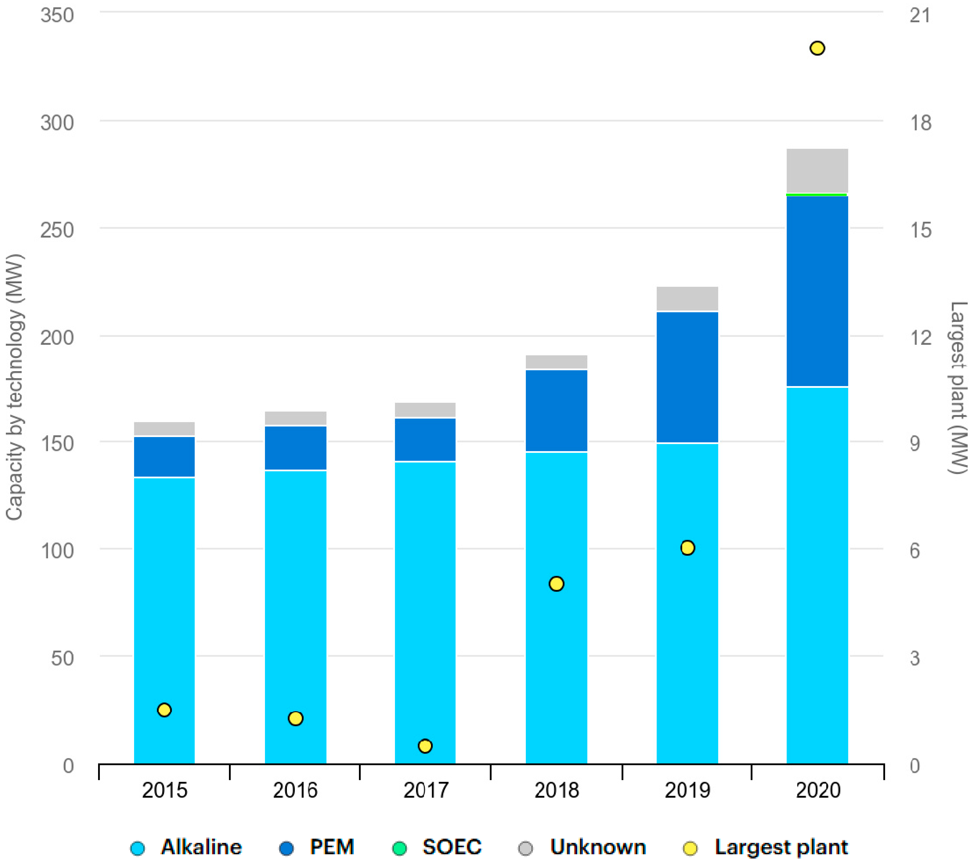
  74. IEA. Global Installed Electrolysis Capacity by Technology, 2015–2020. 4 November 2021. Available online: https://www.iea.org/data-and-statistics/charts/global-installed-electrolysis-capacity-by-technology-2015-2020 (accessed on 28 April 2025).
  75. Sebbahi, S.; Nabil, N.; Alaoui-Belghiti, A.; Laasri, S.; Rachidi, S.; Hajjaji, A. Assessment of the three most developed water electrolysis technologies: Alkaline water electrolysis, proton exchange membrane and solid-oxide electrolysis. Mater. Today Proc. 2022, 66, 140–145. [Google Scholar] [CrossRef]
  76. Ahmed, S.; Krumpelt, M. Hydrogen from hydrocarbon fuels for fuel cells. Int. J. Hydrogen Energy 2001, 26, 291–301. [Google Scholar] [CrossRef]
  77. Pérez-Fortes, M.; Mian, A.; Srikanth, S.; Wang, L.; Diethelm, S.; Varkaraki, E.; Mirabelli, I. Design of a pilot sofc system for the combined production of hydrogen and electricity under refueling station requirements. Fuel Cells 2019, 19, 389–407. [Google Scholar] [CrossRef]
  78. Shikhar, U.; Hemmes, K.; Woudstra, T. Exploring the possibility of using molten carbonate fuel cell for the flexible coproduction of hydrogen and power. Front. Energy Res. 2021, 9, 656490. [Google Scholar] [CrossRef]
  79. Kreuer, K.-D. Proton-conducting oxides. Annu. Rev. Mater. Res. 2003, 33, 333–359. [Google Scholar] [CrossRef]
  80. Nakamura, T.; Mizunuma, S.; Kimura, Y.; Mikami, Y.; Yamauchi, K.; Kuroha, T.; Taniguchi, N.; Tsuji, Y.; Okuyama, Y.; Amezawa, K. Energy efficiency of ionic transport through proton conducting ceramic electrolytes for energy conversion applications. J. Mater. Chem. A 2018, 6, 15771–15780. [Google Scholar] [CrossRef]
  81. Wikipedia. Available online: https://en.wikipedia.org/wiki/Molten_carbonate_fuel_cell (accessed on 24 March 2005).
  82. Contreras, R.R.; Almarza, J.; Rincón, L. Molten carbonate fuel cells: A technological perspective and review. Energy Sources Part A Recovery Util. Environ. Eff. 2021, 1–15. [Google Scholar] [CrossRef]
  83. Hu, L.; Rexed, I.; Lindbergh, G.; Lagergren, C. Electrochemical performance of reversible molten carbonate fuel cells. Int. J. Hydrogen Energy 2014, 39, 12323–12329. [Google Scholar] [CrossRef]
  84. Martsinchyk, A.; Szczęśniak, A.; Martsinchyk, K.; Dybiński, O.; Cinti, G.; Milewski, J.; Shuhayeu, P. Molten carbonate electrolyzer for synthetic fuel generation. J. Power Sources 2025, 628, 235741. [Google Scholar] [CrossRef]
  85. Audasso, E.; Kim, K.I.; Accardo, G.; Kim, H.S.; Yoon, S.P. Investigation of molten carbonate electrolysis cells performance for H2 production and CO2 capture. J. Power Sources 2022, 523, 231039. [Google Scholar] [CrossRef]
  86. Dicks, A.L. Fuel cells—Molten carbonate fuel cells | overview. Encycl. Electrochem. Power Sources 2009, 2, 446–453. [Google Scholar]
  87. Hemmes, K.; Patil, A.; Woudstra, N. Flexible coproduction of hydrogen and power using internal reforming solid oxide fuel cells system. ASME 2008, 5, 041010. [Google Scholar] [CrossRef]
  88. Li, J.; Cai, Q.; Horri, B.A. Highly conductive and stable electrolytes for solid oxide electrolysis and fuel cells: Fabrication, characterisation, recent progress and challenges. Mater. Adv. 2024, 6, 39–83. [Google Scholar] [CrossRef]
  89. Iwahara, H.; Esaka, T.; Uchida, H.; Maeda, N. Proton conduction in sintered oxides and its application to steam electrolysis for hydrogen production. Solid State Ion. 1981, 3, 359–363. [Google Scholar] [CrossRef]
  90. Iwahara, H. Proton conducting ceramics and their applications. Solid State Ion. 1996, 86, 9–15. [Google Scholar] [CrossRef]
  91. Iwahara, H.; Uchida, H.; Morimoto, K. High Temperature Solid Electrolyte Fuel Cells Using Perovskite-Type Oxide Based on BaCeO3. J. Electrochem. Soc. 1990, 137, 462. [Google Scholar] [CrossRef]
  92. Duan, C.; Tong, J.; Shang, M.; Nikodemski, S.; Sanders, M.; Ricote, S.; Almansoori, A.; O’Hayre, R. Readily processed protonic ceramic fuel cells with high performance at low temperatures. Science 2015, 349, 1321–1326. [Google Scholar] [CrossRef] [PubMed]
  93. Minh, N.Q. Ceramic fuel cells. J. Am. Ceram. Soc. 1993, 76, 563–588. [Google Scholar] [CrossRef]
  94. Le, L.Q.; Hernandez, C.H.; Rodriguez, M.H.; Zhu, L.; Duan, C.; Ding, H.; O’Hayre, R.P.; Sullivan, N.P. Proton-conducting ceramic fuel cells: Scale up and stack integration. J. Power Sources 2021, 482, 228868. [Google Scholar] [CrossRef]
  95. Ferguson, K.; Dubois, A.; Albrecht, K.; Braun, R.J. High performance protonic ceramic fuel cell systems for distributed power generation. Energy Convers. Manag. 2021, 248, 114763. [Google Scholar] [CrossRef]
  96. Meisel, C.; Huang, J.D.; Kim, Y.D.; Stockburger, S.; O’Hayre, R.; Sullivan, N.P. Insights on proton-conducting ceramic electrochemical cell fabrication. J. Am. Ceram. Soc. 2025, 108, e20321. [Google Scholar] [CrossRef]
  97. Mu, S.; Zhao, Z.; Huang, H.; Lei, J.; Peng, F.; Xiao, H.; Brinkman, K.S.; Tong, J.J. Advanced Manufacturing of Intermediate-Temperature Protonic Ceramic Electrochemical Cells. Electrochem. Soc. Interface 2020, 29, 67. [Google Scholar] [CrossRef]
  98. Liu, F.; Diercks, D.; Kumar, P.; Seong, A.; Jabbar, M.H.A.; Gumeci, C.; Furuya, Y. Redesigning protonic ceramic electrochemical cells to lower the operating temperature. Sci. Adv. 2025, 11, eadq2507. [Google Scholar] [CrossRef]
  99. Kuzmin, A.V.; Lesnichyova, A.S.; Tropin, E.S.; Stroeva, A.Y.; Vorotnikov, V.A.; Solodyankina, D.M.; Belyakov, S.A. LaScO3-based electrolyte for protonic ceramic fuel cells: Influence of sintering additives on the transport properties and electrochemical performance. J. Power Sources 2020, 466, 228255. [Google Scholar] [CrossRef]
  100. Rehman, J.; Hanif, M.B.; Khan, M.Z.; Ullah, M.; Starostina, I.A.; Muhammad, M.T.; Li, Z. A Review of Proton-Conducting Electrolytes for Efficient Low-Temperature Solid Oxide Fuel Cells: Progress, Challenges, and Perspectives. Energy Fuels 2024, 38, 22637–22665. [Google Scholar] [CrossRef]
  101. Koh, J.-H.; Yoo, Y.-S.; Park, J.-W.; Lim, H.C. Carbon deposition and cell performance of Ni-YSZ anode support SOFC with methane fuel. Solid State Ion. 2002, 149, 157–166. [Google Scholar] [CrossRef]
  102. Maček, J.; Novosel, B.; Marinšek, M. Ni–YSZ SOFC anodes—Minimization of carbon deposition. J. Eur. Ceram. Soc. 2007, 27, 487–491. [Google Scholar] [CrossRef]
  103. Babaei, A.; Zhang, L.; Liu, E. Performance and carbon deposition over Pd nanoparticle catalyst promoted Ni/GDC anode of SOFCs in methane, methanol and ethanol fuels. Int. J. Hydrogen Energy 2012, 37, 15301–15310. [Google Scholar] [CrossRef]
  104. Morozan, A.; Jousselme, B.; Palacin, S. Low-platinum and platinum-free catalysts for the oxygen reduction reaction at fuel cell cathodes. Energy Environ. Sci. 2011, 4, 1238–1254. [Google Scholar] [CrossRef]
  105. Tsai, T.; Barnett, S.A. Effect of LSM-YSZ cathode on thin-electrolyte solid oxide fuel cell performance. Solid State Ion. 1997, 93, 207–217. [Google Scholar] [CrossRef]
  106. Wang, C.C.; Gholizadeh, M.; Hou, B.; Fan, X. Integrated Cr and S poisoning of a La0.6Sr0.4Co0.2Fe0.8O3−δ (LSCF) cathode for solid oxide fuel cells. RSC Adv. 2021, 11, 7–14. [Google Scholar] [CrossRef]
  107. Niedrig, C. Electrochemical Performance and Stability of Ba0.5Sr0.5Co0.8Fe0.2O3-δ for Oxygen Transport Membranes; KIT Scientific Publishing: Karlsruhe, Germany, 2015; Volume 28. [Google Scholar]
  108. Inaba, H.; Tagawa, H. Ceria-based solid electrolytes. Solid State Ion. 1996, 83, 1–16. [Google Scholar] [CrossRef]
  109. Arunkumar, P.; Meena, M.; Babu, K.S. A review on cerium oxide-based electrolytes for ITSOFC. Nanomater. Energy 2012, 1, 288–305. [Google Scholar] [CrossRef]
  110. Robinson, I.A.; Huang, Y.L.; Horlick, S.A.; Obenland, J.; Robinson, N.; Gritton, J.E.; Hussain, A.M.; Wachsman, E.D. Mitigating electronic conduction in ceria-based electrolytes via external structure design. Adv. Funct. Mater. 2024, 34, 2308123. [Google Scholar] [CrossRef]
  111. Xiong, Y.-P.; Kishimoto, H.; Yamaji, K.; Yoshinaga, M.; Horita, T.; Brito, M.E.; Yokokawa, H. Electronic conductivity of pure ceria. Solid State Ion. 2011, 192, 476–479. [Google Scholar] [CrossRef]
  112. Wang, T. Solid-State Oxide Fuel Cells. Appl. Comput. Eng. 2024, 89, 88–93. [Google Scholar] [CrossRef]
  113. Peng, X.-L.; Xu, B.-X. Unraveling impacts of polycrystalline microstructures on ionic conductivity of ceramic electrolytes by computational homogenization and machine learning. J. Appl. Phys. 2024, 10, 136. [Google Scholar] [CrossRef]
  114. Xi, L.; Zhang, D.; Xu, X.; Wu, Y.; Li, F.; Yao, S.; Zhu, M.; Liu, J. Interface Engineering of All-Solid-State Batteries Based on Inorganic Solid Electrolytes. ChemSusChem 2023, 16, e202202158. [Google Scholar] [CrossRef]
  115. Dasari, H.P.; Ahn, K.; Park, S.-Y.; Hong, J.; Kim, H.; Yoon, K.J.; Son, J.-W.; Kim, B.-K.; Lee, H.-W.; Lee, J.-H. Record-low sintering-temperature (600 °C) of solid-oxide fuel cell electrolyte. J. Alloys Compd. 2016, 672, 397–402. [Google Scholar] [CrossRef]
  116. Arshad, M.S.; Billing, C.; Billing, D.G.; Guan, W. Phase-assisted tailored conductivity of doped ceria electrolytes to boost SOFC performance. ACS Appl. Mater. Interfaces 2023, 15, 39396–39407. [Google Scholar] [CrossRef]
  117. Senthil Kumar, S.; Aruna, S.T. Hydrocarbon compatible SOFC anode catalysts and their syntheses: A review. Sustain. Chem. 2021, 2, 707–763. [Google Scholar] [CrossRef]
  118. Wehrle, L.; Wang, Y.; Boldrin, P.; Nigel; Brandon, P.; Deutschmann, O.; Banerjee, A. Optimizing solid oxide fuel cell performance to re-evaluate its role in the mobility sector. ACS Environ. Au 2021, 2, 42–64. [Google Scholar] [CrossRef]
  119. Bertei, A.; Nucci, B.; Nicolella, C. Engineered electrode microstructure for optimization of solid oxide fuel cells. Chem. Eng. Trans. 2013, 32, 2293–2298. [Google Scholar]
  120. Schiller, G.; Ansar, A.S.; Soysal, D. Development of Nanostructured Solid Oxide Fuel Cell Electrodes. World J. Eng. 2010, 7, 220–229. [Google Scholar]
  121. Park, B.-K.; Zhang, Q.; Voorhees, P.W.; Barnett, S.A. Conditions for stable operation of solid oxide electrolysis cells: Oxygen electrode effects. Energy Environ. Sci. 2019, 12, 3053–3062. [Google Scholar] [CrossRef]
  122. Vinchhi, P.; Khandla, M.; Chaudhary, K.; Pati, R. Recent advances on electrolyte materials for SOFC: A review. Inorg. Chem. Commun. 2023, 152, 110724. [Google Scholar] [CrossRef]
  123. Sohal, M.S.; O’Brien, J.E.; Stoots, C.M.; Sharma, V.I.; Yildiz, B.; Virkar, A. Degradation issues in solid oxide cells during high temperature electrolysis. ASME 2011, 9, 011017. [Google Scholar]
  124. Jiang, S.P. Challenges in the development of reversible solid oxide cell technologies: A mini review. Asia Pac. J. Chem. Eng. 2016, 11, 386–391. [Google Scholar] [CrossRef]
  125. Fabbri, E.; Pergolesi, D.; Traversa, E. Materials challenges toward proton-conducting oxide fuel cells: A critical review. Chem. Soc. Rev. 2010, 39, 4355–4369. [Google Scholar] [CrossRef]
  126. Chen, G.; Luo, Y.; Sun, W.; Liu, H.; Ding, Y.; Li, Y.; Geng, S.; Yu, K.; Liu, G. Electrochemical performance of a new structured low temperature SOFC with BZY electrolyte. Int. J. Hydrogen Energy 2018, 43, 12765–12772. [Google Scholar] [CrossRef]
  127. Fabbri, E.; Bi, L.; Pergolesi, D.; Traversa, E. Towards the next generation of solid oxide fuel cells operating below 600 °C with chemically stable proton-conducting electrolytes. Adv. Mater. 2012, 24, 195–208. [Google Scholar] [CrossRef]
  128. Jhuang, J.-W.; Lee, K.-R.; Chang, J.-k.; Shen, C.-T.; Lee, Y.-H.; Lee, S.-W.; Tseng, C.-J. Chemical stability and electrical and mechanical properties of BaZrxCe0.8-xY0.2O3 with CeO2 protection method. Int. J. Hydrogen Energy 2017, 42, 22259–22265. [Google Scholar] [CrossRef]
  129. Jaiswal, N.; Tanwar, K.; Suman, R.; Kumar, D.; Upadhyay, S.; Parkash, O. A brief review on ceria based solid electrolytes for solid oxide fuel cells. J. Alloys Compd. 2019, 781, 984–1005. [Google Scholar] [CrossRef]
  130. Tong, J.; Su, L.; Haraya, K.; Suda, H. Thin Pd membrane on α-Al2O3 hollow fiber substrate without any interlayer by electroless plating combined with embedding Pd catalyst in polymer template. J. Membr. Sci. 2008, 310, 93–101. [Google Scholar] [CrossRef]
  131. Anwar, M.; Muchtar, A.; Somalu, M.R. Effects of various co-dopants and carbonates on the properties of doped ceria-based electrolytes: A brief review. Int. J. Appl. Eng. Res. ISSN 2016, 11, 973–4562. [Google Scholar]
  132. Zhang, Y.; Liu, J.; Singh, M.; Hu, E.; Jiang, Z.; Raza, R.; Wang, F.; Wang, J.; Yang, F.; Zhu, B. Superionic conductivity in ceria-based heterostructure composites for low-temperature solid oxide fuel cells. Nano-Micro Lett. 2020, 12, 178. [Google Scholar] [CrossRef] [PubMed]
  133. Gao, Z.; Mogni, L.V.; Miller, E.C.; Railsback, J.G.; Barnett, S.A. A perspective on low-temperature solid oxide fuel cells. Energy Environ. Sci. 2016, 9, 1602–1644. [Google Scholar] [CrossRef]
  134. Wachsman, E.D.; Lee, K.T. Lowering the temperature of solid oxide fuel cells. Science 2011, 334, 935–939. [Google Scholar] [CrossRef]
  135. Fergus, J.W. Electrolytes for solid oxide fuel cells. J. Power Sources 2006, 162, 30–40. [Google Scholar] [CrossRef]
  136. Kan, W.H.; Samson, A.J.; Thangadurai, V. Trends in electrode development for next generation solid oxide fuel cells. J. Mater. Chem. 2016, 4, 17913–17932. [Google Scholar] [CrossRef]
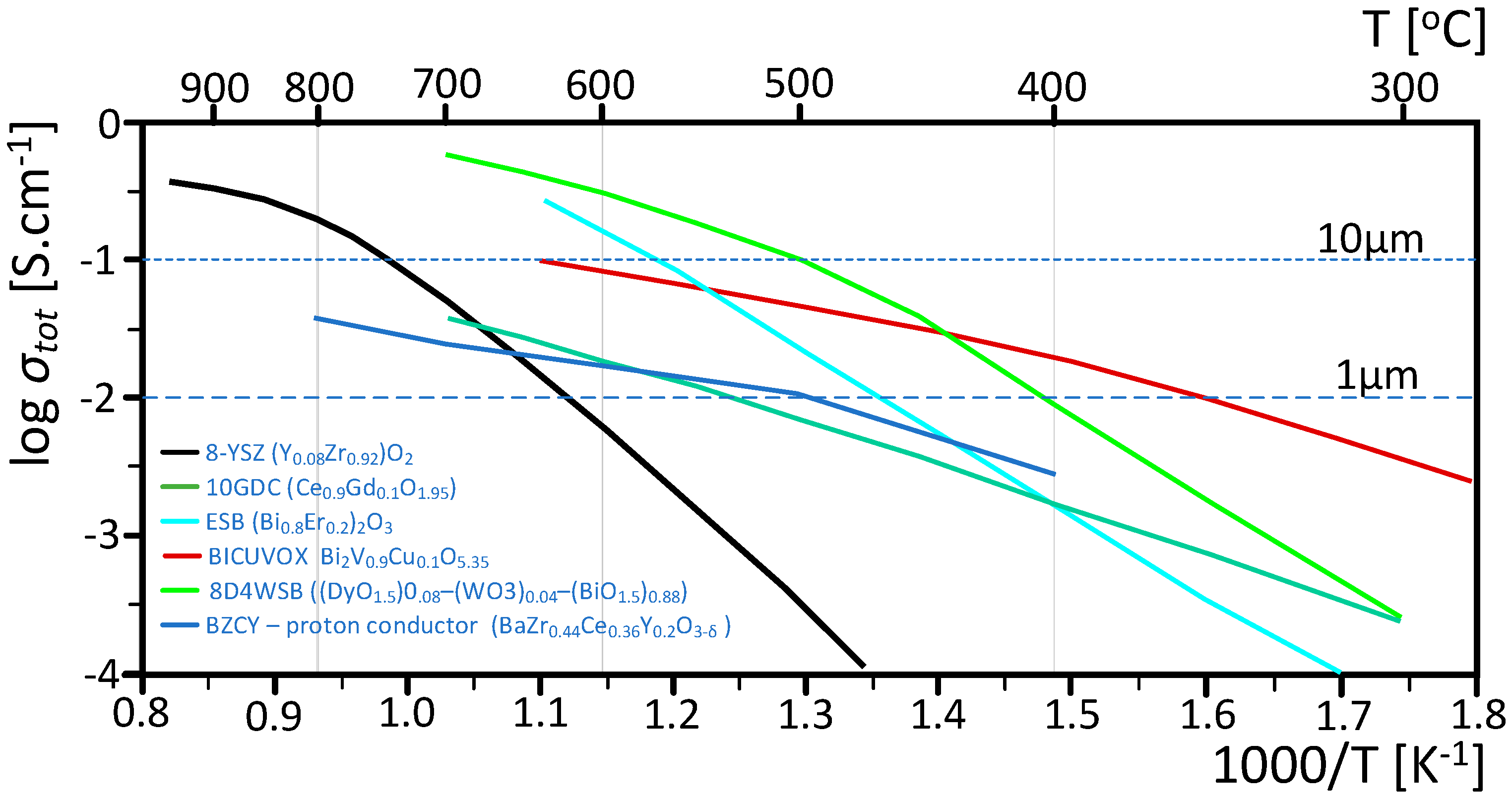
  137. Simner, S.P.; Suarez-Sandoval, D.; Mackenzie, J.D.; Dunn, B. Synthesis, densification, and conductivity characteristics of BICUVOX oxygen-ion-conducting ceramics. J. Am. Ceram. Soc. 1997, 80, 2563–2568. [Google Scholar] [CrossRef]
  138. Punn, R.; Feteira, A.M.; Sinclair, D.C.; Greaves, C. Enhanced oxide ion conductivity in stabilized δ-Bi2O3. J. Am. Chem. Soc. 2006, 128, 15386–15387. [Google Scholar] [CrossRef]
  139. Kwon, O.H.; Choi, G.M. Electrical conductivity of thick film YSZ. Solid State Ion. 2006, 177, 3057–3062. [Google Scholar] [CrossRef]
  140. Jung, D.W.; Duncan, K.L.; Wachsman, E.D. Effect of total dopant concentration and dopant ratio on conductivity of (DyO1.5)x−(WO3)y−(BiO1.5)1−x−y. Acta Mater. 2010, 58, 355–363. [Google Scholar] [CrossRef]
  141. Kuterbekov, K.A.; Nikonov, A.V.; Bekmyrza, K.Z.; Pavzderin, N.B.; Kabyshev, A.M.; Kubenova, M.M.; Kabdrakhimova, G.D.; Aidarbekov, N. Classification of solid oxide fuel cells. Nanomaterials 2022, 12, 1059. [Google Scholar] [CrossRef] [PubMed]
  142. Yang, Z.; Xia, G.-G.; Li, X.-H.; Stevenson, J.W. (Mn, Co)3O4 spinel coatings on ferritic stainless steels for SOFC interconnect applications. Int. J. Hydrogen Energy 2007, 32, 3648–3654. [Google Scholar] [CrossRef]
  143. Puranen, J.; Pihlatie, M.; Lagerbom, J.; Bolelli, G.; Laakso, J.; Hyvärinen, L.; Kylmälahti, M. Post-mortem evaluation of oxidized atmospheric plasma sprayed Mn–Co–Fe oxide spinel coatings on SOFC interconnectors. Int. J. Hydrogen Energy 2014, 39, 17284–17294. [Google Scholar] [CrossRef]
  144. Gannon, P.; Deibert, M.; White, P.; Smith, R.; Chen, H.; Priyantha, W.; Lucas, J.; Gorokhovsky, V. Advanced PVD protective coatings for SOFC interconnects. Int. J. Hydrogen Energy 2008, 33, 3991–4000. [Google Scholar] [CrossRef]
  145. Gorokhovsky, V.I.; Gannon, P.E.; Deibert, M.C.; Smith, R.J.; Kayani, A.; Kopczyk, M.; VanVorous, D. Deposition and evaluation of protective PVD coatings on ferritic stainless steel SOFC interconnects. J. Electrochem. Soc. 2006, 153, A1886–A1893. [Google Scholar] [CrossRef]
  146. Bobruk, M.; Molin, S.; Chen, M.; Brylewski, T.; Hendriksen, P.V. Sintering of MnCo2O4 coatings prepared by electrophoretic deposition. Mater. Lett. 2018, 213, 394–398. [Google Scholar] [CrossRef]
  147. Shaigan, N.; Qu, W.; Ivey, D.G.; Chen, W. A review of recent progress in coatings, surface modifications and alloy developments for solid oxide fuel cell ferritic stainless steel interconnects. J. Power Sources 2010, 195, 1529–1542. [Google Scholar] [CrossRef]
  148. Molin, S.; Jasinski, P.; Mikkelsen, L.; Zhang, W.; Chen, M.; Hendriksen, P.V. Low temperature processed MnCo2O4 and MnCo1.8Fe0.2O4 as effective protective coatings for solid oxide fuel cell interconnects at 750 °C. J. Power Sources 2016, 336, 408–418. [Google Scholar] [CrossRef]
  149. Molin, S.; Chen, M.; Hendriksen, P.V. Oxidation study of coated Crofer 22 APU steel in dry oxygen. J. Power Sources 2014, 251, 488–495. [Google Scholar] [CrossRef]
  150. Lee, K.; Yoon, B.; Kang, J.; Lee, S.; Bae, J. Evaluation of Ag-doped (MnCo)3O4 spinel as a solid oxide fuel cell metallic interconnect coating material. Int. J. Hydrogen Energy 2017, 42, 29511–29517. [Google Scholar] [CrossRef]
  151. Xu, Y.; Wen, Z.; Wang, S.; Wen, T. Cu doped Mn–Co spinel protective coating on ferritic stainless steels for SOFC interconnect applications. Solid State Ion. 2011, 192, 561–564. [Google Scholar] [CrossRef]
  152. Chen, G.; Xin, X.; Luo, T.; Liu, L.; Zhou, Y.; Yuan, C.; Lin, C.; Zhan, Z.; Wang, S. Mn1.4Co1.4Cu0.2O4 spinel protective coating on ferritic stainless steels for solid oxide fuel cell interconnect applications. J. Power Sources 2015, 278, 230–234. [Google Scholar] [CrossRef]
  153. Uehara, T.; Yasuda, N.; Okamoto, M.; Baba, Y. Effect of Mn–Co spinel coating for Fe–Cr ferritic alloys ZMG232L and 232J3 for solid oxide fuel cell interconnects on oxidation behavior and Cr-evaporation. J. Power Sources 2011, 196, 7251–7256. [Google Scholar] [CrossRef]
  154. Singh, R.; Pratap, R.; Narayanan, J.A.; Thangamani, G.; Krishnan, V.V.; Arjunan, A.; Hughes, D. Advances in additive manufacturing of fuel cells: A review of technologies, materials, and challenges. Sustain. Mater. Technol. 2025, 43, e01317. [Google Scholar] [CrossRef]
  155. Pesce, A.; Hornés, A.; Núñez, M.; Morata, A.; Torrell, M.; Tarancón, A. 3D printing the next generation of enhanced solid oxide fuel and electrolysis cells. J. Mater. Chem. 2020, A8, 16926–16932. [Google Scholar] [CrossRef]
  156. Wei, L.; Zhang, J.; Yu, F.; Zhang, W.; Meng, X.; Yang, N.; Liu, S. A novel fabrication of yttria-stabilized-zirconia dense electrolyte for solid oxide fuel cells by 3D printing technique. Int. J. Hydrogen Energy 2019, 44, 6182–6191. [Google Scholar] [CrossRef]
  157. Han, G.D.; Bae, K.; Kang, E.H.; Choi, H.J.; Shim, J.H. Inkjet printing for manufacturing solid oxide fuel cells. ACS Energy Lett. 2020, 5, 1586–1592. [Google Scholar] [CrossRef]
  158. Zouridi, L.; Garagounis, I.; Vourros, A.; Marnellos, G.E.; Binas, V. Advances in Inkjet-Printed Solid Oxide Fuel Cells. Adv. Mater. Technol. 2022, 7, 2101491. [Google Scholar] [CrossRef]
  159. Jang, I.; Kelsall, G.H. Fabrication of 3D NiO-YSZ structures for enhanced performance of solid oxide fuel cells and electrolysers. Electrochem. Commun. 2022, 137, 107260. [Google Scholar] [CrossRef]
  160. Anelli, S.; Rosa, M.; Baiutti, F.; Torrell, M.; Esposito, V.; Tarancón, A. Hybrid-3D printing of symmetric solid oxide cells by inkjet printing and robocasting. Addit. Manuf. 2022, 51, 102636. [Google Scholar] [CrossRef]
  161. Lamy, C. From hydrogen production by water electrolysis to its utilization in a PEM fuel cell or in a SO fuel cell: Some considerations on the energy efficiencies. Int. J. Hydrogen Energy 2016, 41, 15415–15425. [Google Scholar] [CrossRef]
Figure 1. Carbon-neutral society [14].
Energies 18 02493 g001
Figure 2. Comparison between the efficiency of a solid oxide fuel cell operating at 80% of idealized thermodynamic efficiency and utilizing 90% of the supplied fuel, against the calculated efficiency of heat machines rejecting heat at a temperature of 70 °C, including the idealized Carnot efficiency and the Endoreversible Efficiency for a heat machine.
Energies 18 02493 g002
Figure 3. Calculated ∆H and TS for the dry reforming reaction of CH4 followed by the oxidation of the produced CO in the fuel cell. The heat balance of the fuel cell fortuitously ends up canceling each other out.
Energies 18 02493 g003
Figure 4. General trends of the calculated r H T o , T r S T o , and r G T o for the hydrogen–oxygen reaction based on the Shomate parameters.
Energies 18 02493 g004
Figure 6. Relative properties of electrical plasmas [62]. The blue arrow shows the increase in electron temperature, and the red arrow represents the increase in (sensible) gas temperature.
Energies 18 02493 g006
Figure 7. Global installed electrolysis capacity by technology, 2015–2020 [74].
Energies 18 02493 g007
Figure 8. Solid oxide electrochemical devices functioning in (a) galvanic/fuel cell mode; (b) electrolytic modes; and (c) a molten carbonate fuel cell [81].
Energies 18 02493 g008
Figure 9. Total conductivities of electrolyte materials that have been successfully employed in low-temperature SOFCs. The lines shown represent the center of mass of the reported conductivity values, which vary by as much as a factor of 3. The horizontal dotted (dashed) line indicates the conductivity requirement to achieve an area-specific resistance < 0.1 Ω cm2 for a 10 μm (1 μm) thickness [133,134,135,136,137,138,139,140].
Energies 18 02493 g009
Table 1. Shomate parameters for the temperature range of interest for solid oxide electrochemical systems used in Equations (4) and (5) to develop Figure 2, Figure 3 and Figure 4.
Species
Param.H2O2COCH4H2O (g)H2O (L)CO2
A33.0661831.3223425.567590.70302930.092203.60624.99735
B−11.3634−20.23536.096130108.47736.8325141523.2955.18696
C11.4328257.866444.05465642.521576.7934353196.41333.69137
D−2.77287−36.50622.6713015.862788−2.534482474.4557.948387
E−0.15856−0.007370.1310210.6785650.0821393.8553260.136638
F−9.9808−8.90347118.008976.84376−250.881256.5478403.6075
G172.708246.7945227.3665158.7163223.3967488.7163228.2431
H00110.527174.87310−241.826285.8304393.5224
Table 2. Electrochemical system advantages and disadvantages.
Electrochemical System TypeAdvantagesDisadvantages
Low Temperature:
Alkaline, Phosphoric Acid, Polymer Electrolyte Membrane (PEM), Direct Methanol PEM
Simple to Operate,
Fast Dynamic Response,
Commercial Maturity
Lower Efficiency,
Noble Metal Catalysts (e.g., Pt, Ru),
Strict Fuel Purity Constraints
High Temperature:
Molten Carbonate, Solid Oxide
High Efficiency,
Heat Recovery Enables Higher Fuel Utilization,
Non-Noble Metal Catalysts (e.g., Ni),
Internal Hydrocarbon Fuel Processing Capability,
Lower Sensitivity to Poisoning
Challenging Operational Conditions,
Slower Dynamic Response,
Pre-Commercial Maturity
Disclaimer/Publisher’s Note: The statements, opinions and data contained in all publications are solely those of the individual author(s) and contributor(s) and not of MDPI and/or the editor(s). MDPI and/or the editor(s) disclaim responsibility for any injury to people or property resulting from any ideas, methods, instructions or products referred to in the content.

