Article

Oscillations of the Oil Pipeline Axis with Consideration of the Inertia Component When Pumping Diesel Fuel

1
Department of Energy Transportation and Storage, Ivano-Frankivsk National Technical University of Oil and Gas, 76019 Ivano-Frankivsk, Ukraine
2
Department of Mining Engineering and Education, Dnipro University of Technology, 49005 Dnipro, Ukraine
*
Author to whom correspondence should be addressed.
Energies 2025, 18(10), 2472; https://doi.org/10.3390/en18102472
Submission received: 8 April 2025 / Revised: 29 April 2025 / Accepted: 10 May 2025 / Published: 12 May 2025
(This article belongs to the Special Issue Advances in Gas Transportation by Pipeline and LNG)

Abstract

:
This study examines a single-span beam crossing without longitudinal deformation compensators during diesel fuel pumping. In addition to static forces, namely, the weight of the pipeline and the transported product, the analysis considers vertical components of inertial forces acting on the oil product and the pipeline itself. These forces are directed perpendicularly to the abscissa axis connecting the endpoints of the crossing. The inertial effects cause significant vertical oscillations of the pipeline, which have not been sufficiently addressed in previous research. This work aims to study these oscillations to determine the displacements of points along the pipeline axis, the magnitudes of the inertial forces, and the resulting bending moments at the crossing. A classical Fourier series method is applied to solve the formulated boundary value problem. The results show that oscillations occur in the vertical plane, are symmetrical relative to the center of the span, and are undamped. The maximum vertical displacement reaches approximately 57 mm at the midpoint of the crossing, and the oscillation period is around 0.415 s. Inertial force distribution and bending moments are also symmetric about the center. A detailed analysis with small time steps confirmed that the oscillations are strictly periodic, exhibiting equal displacements in the upward and downward directions. The results highlight that fatigue loads arise during the operation of such crossings, which is important for assessing the strength and stability of oil pipeline structures under real operating conditions.

1. Introduction

Despite the intensive development of alternative energy sources, hydrocarbons and fossil fuels still play a crucial role in the energy balance of many countries worldwide [1]. The transportation of petroleum products through pipelines remains a key component of the global energy infrastructure, requiring the establishment of reliable and secure routes [2]. This need becomes particularly critical in challenging environments such as mountainous regions [3,4,5] and offshore areas [6], where the risks associated with pipeline operations increase significantly. Any leakage of hydrocarbons from these systems can cause serious environmental pollution, leading to long-term ecological consequences and economic losses [7,8].
Today, the main oil pipelines are complex engineering structures subject to significant operational loads throughout their life cycle. These systems stretch for tens and sometimes hundreds of kilometers, crossing various natural and anthropogenic obstacles [9,10]. Due to their length, each additional millimeter of pipe wall thickness leads to a significant increase in material consumption and, consequently, an increase in the total project cost. Therefore, oil pipelines are designed with the lowest possible safety factors based on limit state calculations. This approach ensures cost-effectiveness but makes the system more sensitive to abnormal impacts during long-term operation [11,12,13].
In addition to normal loads, such as the weight of pipes, the weight of the transported oil product, and internal pressure, main oil pipelines experience complex dynamic and temperature effects. Particularly vulnerable are sections of aboveground crossings [14], where inertial forces arising from the movement of the liquid cause the pipeline axis to co-localize. This leads to the appearance of additional stresses, which can reach the limit values. The pipeline system is also exposed to an aggressive environment: corrosion [15,16], crack formation [17,18,19,20,21,22], material aging, and gradual degradation of metal mechanical properties. It should be noted here that protective coatings play a key role in preventing corrosion processes, extending the service life of oil pipelines, and reducing the risk of accidents [23,24]. These processes become especially critical under conditions of long-term operation, when the material structure exhausts its strength reserves [25].
Recent studies have also proposed advanced approaches for assessing the remaining service life of oil and gas infrastructure based on neural network modeling [26], digital 3D modeling [27] and for improving corrosion resistance through the application of phosphate inhibitors [28], which are highly relevant to the long-term safe operation of steel pipelines under aggressive environmental conditions.
Significant daily or seasonal temperature variations also contribute to the appearance of thermal deformations [29], affecting pipelines’ integrity and durability. A parallel can be drawn from controlled thermal processes like friction drilling, where temperature fluctuations directly impact surface roughness, structural integrity, and microstructural evolution in aluminum alloys [30,31,32], highlighting the critical role of thermomechanical effects in structural performance.
The condition of the soil base plays an equally important role. Changes in its elastic properties, the formation of cavities, local cavities, or soil slippage can cause uneven load distribution and local deformation of the pipeline [33,34,35,36]. In the areas of contact between the pipe and the supports, stress concentrations are often observed, which increases the risk of fatigue failure [37]. This is especially true for areas subject to periodic vibrations and wave disturbances caused by dynamic and inertial loads [38,39,40]. Analytical and numerical approaches to the simulation of unsteady processes in deformable rods under conditions of nonlinear interaction of the lateral surface with the environment are described in papers [41,42,43,44,45,46,47].
Studying the influence of these factors allows us to predict possible scenarios of oil pipeline behavior, and integrating this knowledge into design processes helps to develop design solutions that increase pipeline systems’ operational reliability and durability even in the most difficult conditions.
The reliability indicators of pipelines [48] are significantly influenced by a range of factors, including the chemical composition and quality of the pipe metal [49], the stress state arising during operation [50], and the specific transportation modes employed, particularly reverse flow modes [51]. In addition, corrosion processes [52,53], the presence of aggressive gases within the transported hydrocarbons [54,55], progressive metal degradation [56], mechanical wear [31], and the elevated temperatures of the transported fluids [32] also contribute to the deterioration of pipeline reliability. These factors, individually or collectively, can critically impact the safe and efficient operation of pipeline systems over time. To assess the technical condition of welds [57] and pipeline coatings, image processing methods [58] are promising, particularly in hard-to-reach areas of pipelines.
Periodic cleaning of pipelines from deposits using a cleaning pig is an important condition for their reliable operation. The movement of the cleaning pig causes additional dynamic loads, especially in the areas of bends and tees, which affect the stress–strain state of the system. Studies [59,60] analyzed how friction forces between an elastic piston and the pipe wall, material characteristics, and piston design affect the dynamics of its movement in complex pipeline sections.
Several papers appeared from 2019 to 2024 addressing some of the above issues. Researchers pay considerable attention to the integrity of pipelines, especially long ones. Amandi et al. [61] present a new and improved model for assessing the residual strength of pipelines, which is characterized by a reduction in conservatism compared to existing models (for example, in cases where corrosion sites on the pipeline occur close enough to each other so that there is an interaction between them). Vanitha et al. [62] proposed a probabilistic machine learning method for assessing pipeline integrity that considers corrosion, pipe leaks, materials, atmosphere, aboveground and underground structures, etc. This method provides high accuracy in assessing pipeline integrity. An economical and effective method for replacing partially damaged oil pipelines is discussed in the article by Fan et al. [63]. The essence of the process is introducing a temporary plugging material to isolate the locally damaged pipeline.
Determining the mechanisms of failure of suspended pipelines in cases of natural disasters was investigated in Yu et al. [64]. In this case, a nonlinear finite element method was used to consider the pipe’s nonlinear contact with the soil and plastic deformation.
The operation of underground pipelines under conditions of soil subsidence results in their deformation and potential failure [65,66]. A laboratory testing setup was developed in [67] to investigate how factors such as burial depth, soil cohesion, and internal friction angle under loading influence the deformation behavior of the pipe–soil system, the pressure distribution around the pipeline, and the variation of additional axial stresses along its length. It is also noteworthy that pipelines are utilized in processes such as underground coal gasification [68,69,70] and conventional ore mining [71,72,73].
The papers of Kopei et al. [74,75] show that to ensure the reliable operation of pipelines, it is important to ensure the tightness of threaded connections.
Researchers Velychkovych et al. [76] developed a mechanical and mathematical model of a beam crossing laid in mountainous terrain for the case of uniformly distributed static forces to take into account the properties of the crossing’s soil based on its strength. The model consists of a symmetrical half of the overhead crossing and an underground section in direct contact. As a result of solving the differential equations for the overhead and underground sections of the crossing, the force and geometric parameters in the common plane of the overhead and underground sections of the crossing were found. The studies have shown the influence of a significant redistribution of loads in the aboveground section of the oil pipeline beam crossing due to changes in the stiffness of the soil base.
For pipeline transportation, the problem of trouble-free operation is extremely important. This is achieved by analyzing the reliability of its operation, which is the basis for developing its anticorrosive structures and technology for their maintenance [77]. Bi et al. [78] present a method for obtaining the reliability function of a corroded pipeline. It was found that the service life of the pipeline decreases with increasing temperature and over time. This publication provides a scientific basis for managing the safety of oil and gas pipelines. The arrangement of pipelines relative to each other, for example, in two strands [79], can also affect the vibrations of the tubes and their operating conditions [80]. Dutkiewicz et al. [81] investigate the interaction of an oil pipeline with its support built in a mountainous area.
The scientific works of Dutkiewicz et al. [82] and Dey and Tesfamariam [83] have in common the deformation of pipes caused by the displacement of the upper layers of soil. In the first case, these were actual gas wells in which transverse deformation of the casing pipes occurred. As a result, the wellbore was tilted, and their further operation was jeopardized. In the second case, for the same reason, tensile deformation of the buried pipeline pipes occurred, and there was a risk of their destruction. The first paper uses an analytical method, namely, differential equations, and the second paper uses a three-dimensional nonlinear finite element model. Both papers develop ways to solve problems related to pipelines and oil and gas wells located in seismically active zones.
This paper considers one of the three components of the inertial forces that occur at beam crossings during the operation of oil pipelines. This inertia force does not depend on the speed of the oil product in the pipeline. It is directed perpendicular to the abscissa axis, which passes through the end points of the axis of the beam transition.
The purpose of this study was to investigate the oscillations of the axis of the beam transition pipes to find the value of the specified force of inertia and the bending moments of the transition pipes caused by the specified force of inertia.

2. Materials and Methods

This article determines the deflections of the oil pipeline axis when pumping one of the oil products, namely diesel fuel, through its overhead crossing. A single-span overhead crossing without longitudinal deformation compensators was considered, the ends of which are clamped. The material of the crossing pipes is 13GS steel (TU 14-3-1573-96), the outer and inner diameters of which are 529 mm and 509 mm. The tensile strength of 13GS steel is 510 MPa, and its yield strength is 360 MPa.
The deflections of the oil pipeline axis were determined considering one of the components of the inertial forces of the pumped oil product, which does not depend on its speed in the pipeline, and the inertial force of the pipes at the transition, which are equally directed.
It is known that during the transportation of petroleum products through oil pipelines, their speed is usually 5 m/s, and sometimes less (1.4 m/s) [84].
In our study, one component of the inertial force perpendicular to the beam was considered. This component takes into account the mass of both the diesel fuel and the mass of the transition pipes. The components of the inertial forces of the diesel fuel mass (Coriolis and centrifugal) were not taken into account. It is impossible to consider them using the classical Fourier method; it is necessary to apply the modified Fourier method, which is based on the method of two-wave representation of oscillations in the form of a superposition of natural and accompanying oscillations.
We will use the following method to estimate the numerical values of the unaccounted inertial forces. The elastic line of the beam will be considered as an arc of a circle passing through the clamped ends of the beam and the point of the axis of the midsection (x = 15 m) at its maximum displacement, umax = 57 mm, obtained from the results of our research. We will use the known speed of the oil product v = 5 m/s, the length of the transition L = 30 m, and the mass of one meter of diesel fuel in the pipe of the beam transition q2/g = 175.025 kg/m. Under these conditions, the radius of the circle of the elastic line of the axis of the oil pipeline at the transition will be r = 1973.712 m, and the average angular velocity during the movement of diesel fuel will be ω = 0.002633 s−1.
As a result, the centrifugal force of inertia during the movement of diesel fuel in the oil pipeline will be q2/g(ω2·r) = 2.2 N/m.
The Coriolis force of inertia will have the same numerical order. Still, it will be slightly larger because it is proportional to the first power of the angular velocity during the movement of diesel fuel in the oil pipeline.
The small values of the inertia forces (Coriolis and centrifugal) not taken into account in the model are the small speeds of movement of the oil product in the oil pipeline.
Since this study aimed to determine the effect of these inertial forces on the deflection of the oil pipeline axis at an overpass, this required solving a boundary value problem with a term containing these inertial forces in the differential equation. If the inertial forces are neglected, then the deflections of the oil pipeline axis will be the same as in the case of a stationary oil product in the pipeline. This means that the deflections will be determined by static forces, namely the weight of the pipeline pipes and the oil product at the transition section. The boundary conditions for the clamped ends of the above-ground section of the crossing mean that the displacements and pipe rotation angles are equal to zero at the ends of the crossing. The initial conditions of the problem were determined through the given weight of the pipes and the pumped oil product at the above-ground crossing. The above forces of inertia are directed perpendicular to the horizontal abscissa axis X, which passes through the endpoints of the oil pipeline axis at the crossing (Figure 1). In addition to the deflections of the oil pipeline axis at the overhead crossing, the values of inertial forces and bending moments of pipes were also determined as a function of the crossing coordinate x and time t of the oil product movement in the pipeline.
The differential equation that describes the deflection (displacement of points) of the oil pipeline axis in this case takes the following form:
q 1 + q 2 g · 2 u t 2 + E I 4 u x 4 = 0 .
Boundary and initial conditions of the problem
u / x = 0 = 0 ,       u x x = 0 = 0 ,       u / x = L = 0 ,       u x / x = L = 0 ,
u / t = 0 = q 1 + q 2 2 E I x 4 12 L x 3 6 + L 2 x 2 12 ,       u t / t = 0 = 0 ,
where u is the displacement of the points of the oil pipeline axis from the X-axis in the direction of the Y-axis; x and t are the coordinates of the oil pipeline axis and the time from the beginning of the oil product movement in the aboveground beam crossing; q 1 , q 2 —weight of one meter of the pipeline pipe and one meter of the oil product in the pipeline; E I —elastic modulus of the pipeline pipe material and axial moment of inertia of its cross-sectional area; L and g are the length of the aboveground section of the oil pipeline and the acceleration of free fall.
A similar partial differential equation for another applied problem was recently investigated by Striletskyi et al. [85]. The approach developed by Bandura and Skaskiv [86] and Bandura et al. [87] was used. Under the mathematical modeling, it is important to construct a model using a modern mathematical approach—Shah’s differential equation [88], multiple Dirichlet series [89], directional bounded L-index [90], bounded value distribution [91]. It allows for a deep description of local and global properties of the analytic solution.
The first initial condition (3) determines the deflection of the oil pipeline axis at the transition under the action of uniformly distributed forces and was determined by revealing the static uncertainty of the beam transition by the method of forces Gere et al. [92]. To obtain the solution to the mathematically formulated problem, the classical Fourier method was used by Fridman [93].

3. Results

The following analytical expression represented the unknown function u(x,t):
u x , t = ϕ x A c o s ω t + B s i n ω t ,
where ϕ x is the eigenfunction of the problem (Fourier method).
After substituting (4) into the differential Equation (1), the equation for the eigenfunction of the problem is obtained
ϕ I V α 4 ϕ = 0 ,
where α 4 = q 1 + q 2 g E I ω 2 .
The solution to Equation (5) has the form [94]
ϕ x = C 1 K 1 α x + C 2 K 2 α x + C 3 K 3 α x + C 4 K 4 α x ,
where C i ,   i = 1 ,   2 ,   3 ,   4 are the integration constants of Equation (5); K i α x —Krylov’s functions;
K 1 α x = 1 2 c h α x + c o s α x ,       K 2 α x = 1 2 s h α x + s i n α x , K 3 α x = 1 2 c h α x c o s α x ,       K 4 α x = 1 2 s h α x s i n α x .
Each of the functions (6) satisfies Equation (5). Still, the functions K 1 α x i K 2 α x do not satisfy the boundary conditions, so C 1 = C 2 = 0 . To determine the unknown coefficients C 3 i C 4 , the following two equations are obtained:
C 3 K 3 α L + C 4 K 4 α L = 0 , C 3 K 2 α L + C 4 K 3 α L = 0 .
System (7) is a system of two homogeneous equations. Such a system has a non-trivial solution if the discriminant for the unknowns is zero, i.e., if
K 3 2 α L K 2 α L K 4 α L = 0 .
As a result of substituting the analytical expressions for the Krylov functions into Equation (8) and making simplifications, we obtain
c h α L c o s α L = 1 .
After marking α L = λ , Equation (9) took the form
c h λ c o s λ = 1 .
This equation is transcendental. It has many roots, so the eigenfunction of the problem must be of the form
ϕ k x = C 3 K 3 λ k L x + C 4 K 4 λ k L x ,   k = 1 , 2 , 3 , .
The first Equation (7) is used to find the integration constants. Substituting in this equation C 3 = K 4 λ k , then C 4 = K 3 λ k . After substituting these values for C 3 i C 4 in Equation (10), the eigenfunction of the problem is obtained in its final form
ϕ k x = K 4 λ k K 3 λ k L x K 3 λ k K 4 λ k L x .
As a result of substituting the analytical expression for the eigenfunctions (11) in (4), the relationship between the desired function u(x,t) and the unknown coefficients is found A k in the form of
u x , t = k = 1 A k K 4 λ k K 3 λ k L x K 3 λ k K 4 λ k L x c o s ω k t
The coefficients B k are equal to zero due to the fulfillment of the second initial condition (3), which is zero. In (12), the coefficients A k . Value λ k is called the eigenvalue of the problem, and ω k —the natural frequency of oscillations, which is found from Equation (5)
ω k = λ k 2 L 2 g E I q 1 + q 2
To determine the unknown coefficients A k the first initial condition (3) and Equation (12) at t = 0 . This resulted in the following equation
q 1 + q 2 2 E I x 4 12 L x 3 6 + L 2 x 2 12 = k = 1 A k K 4 λ k K 3 λ k L x K 3 λ k K 4 λ k L x .
Next, the left and right sides of Equation (14) were multiplied by
K 4 λ i K 3 λ i L x K 3 λ i K 4 λ i L x
and integrated in the range from 0 to L. Taking into account the orthogonality of the eigenfunctions, the following equation is obtained:
q 1 + q 2 2 E I 0 L x 4 12 L x 3 6 + L 2 x 2 12 K 4 λ i K 3 λ i L x K 3 λ i K 4 λ i L x d x = A i 0 L K 4 λ i K 3 λ i L x K 3 λ i K 4 λ i L x 2 d x .
The integral on the right is known in A. Filippov (1965) [94]
0 L K 4 λ i K 3 λ i L x K 3 λ i K 4 λ i L x 2 d x = L 4 K 4 λ i K 1 λ i K 3 λ i K 2 λ i 2
After integrating on the left and simplifying the resulting expression, the unknown coefficients are found
A i = q 1 + q 2 L 4 3 E I s h λ i c o s λ i c h λ i s i n λ i 2 · 24 λ i 5 c h λ i s h λ i s i n λ i c o s λ i .
Substituting (15) into (12), we obtain the final solution to the problem (1)–(3)
u x , t = 8 q 1 + q 2 L 4 E I i = 1 c h λ i s h λ i s i n λ i c o s λ i λ i 5 s h λ i c o s λ i c h λ i s i n λ i 2 K 4 λ i K 3 λ i L x K 3 λ i K 4 λ i L x c o s ω i t .
To find the total force of inertia, which is directed along the y-axis, we used the found function of displacements of the points of the axis of the oil pipeline overpass u(x,t) and, after simplifications, obtained the following analytical expression for the total force of inertia:
P i n = q 1 + q 2 g 2 u t 2 = 8 q 1 + q 2 i = 1 c h λ i s h λ i s i n λ i c o s λ i λ i s h λ i c o s λ i c h λ i s i n λ i 2 K 4 λ i K 3 λ i L x K 3 λ i K 4 λ i L x c o s ω i t .
The analytical expression for the function of bending moments of the pipeline at the above-ground transition of the oil pipeline was also obtained through the function u(x,t) in the form
M = E I 2 u x 2 = 8 q 1 + q 2 L 2 i = 1 c h λ i s h λ i s i n λ i c o s λ i λ i 3 s h λ i c o s λ i c h λ i s i n λ i 2 K 4 λ i K 1 λ i L x K 3 λ i K 2 λ i L x c o s ω i t .
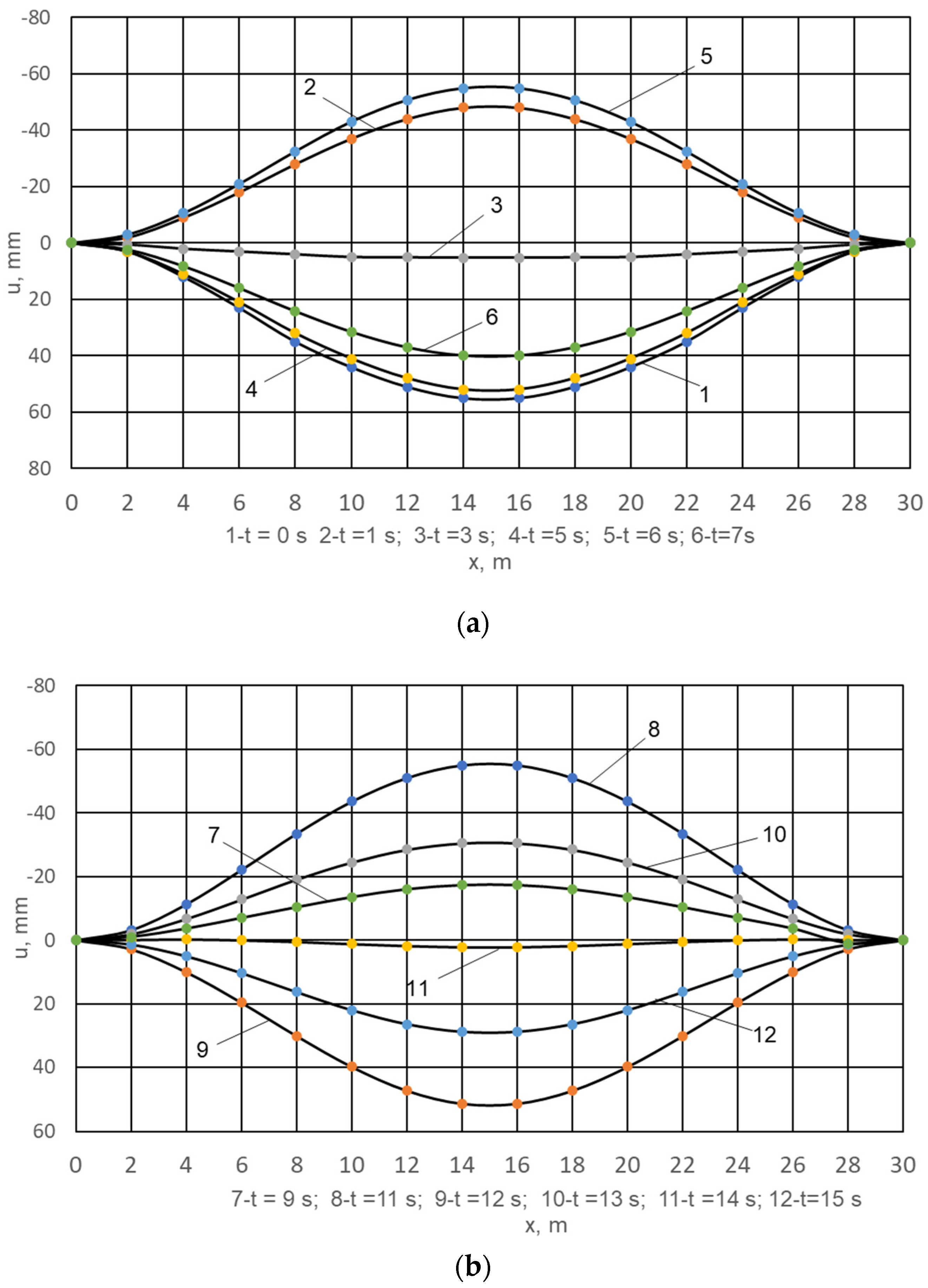
Formulas (16)–(18) were used to calculate the displacements of the axis points of the oil pipeline beam transition pipes, the inertia force P I N and the bending moment M. The initial data of these calculations are as follows: the density of the pipe metal ρ i = 7850   k g / m 3 , outer and inner diameter of pipes at the transition D 3 = 0.529   m , D B = 0.509   m , modulus of elasticity of pipe metal E = 2.05 · 10 11   P a , axial moment of inertia of the cross-sectional area of oil pipeline pipes I = 0.000549   m 4 , length of the beam transition L = 30   m , weight per unit length of oil pipeline pipe q 1 = 1256   N / m and weight per unit length of diesel fuel in the pipeline q 2 = 1717   N / m . The construction is based on the results of calculations with steps x = 2   m i t = 1   s . Figure 2 shows the displacement of the axis points of the beam transition pipes for different moments in the range from t = 0 to t = 15   s . Curve 1 in Figure 2a corresponds to the moment t = 0   s , when the pumped product was still stationary in the pipeline.
This means that the deflection represented by curve 1 is caused by static forces q 1 and q 2 . At a moment in time t > 0   s , the movement of diesel fuel in the oil pipeline begins. The deflections of the oil pipeline axis for different moments of time correspond to curves 2–6 (Figure 2a) and 7–12 (Figure 2b). As can be seen from the figures, there is a familiar oscillatory process of the oil pipeline axis relative to the abscissa axis X with unequal deviations up and down, which vary with time. In addition, the movements of the points of the oil pipeline axis are symmetrical relative to the middle of the length of the beam transition. The maximum modulus deflections of the axis for each moment of time correspond to the middle of the beam transition ( x = 15   m ). The most significant positive displacement of the ones shown in Figure 2a,b corresponds to the moment of time t = 0   s and is equal to u / t = 0 = 55.2   m m . However, if we take into account the time period 0 t 47   s , for which the calculation was performed, it turned out that there is a moment in time for which the displacement is greater than the above and corresponds to the moment t = 17   s and is equal to u / t = 17 = 56.5   m m at x = 14   m and x = 16   m . In the time range 0 t 47   s , no periodicity in the change in displacements of the oil pipeline axis points at the beam crossing was recorded. This does not mean that the oscillations of the pipeline axis are not periodic. To determine whether the oscillations of the oil pipeline axis are periodic or non-periodic, it is necessary to calculate the displacements of the oil pipeline axis at the crossing at small steps t .
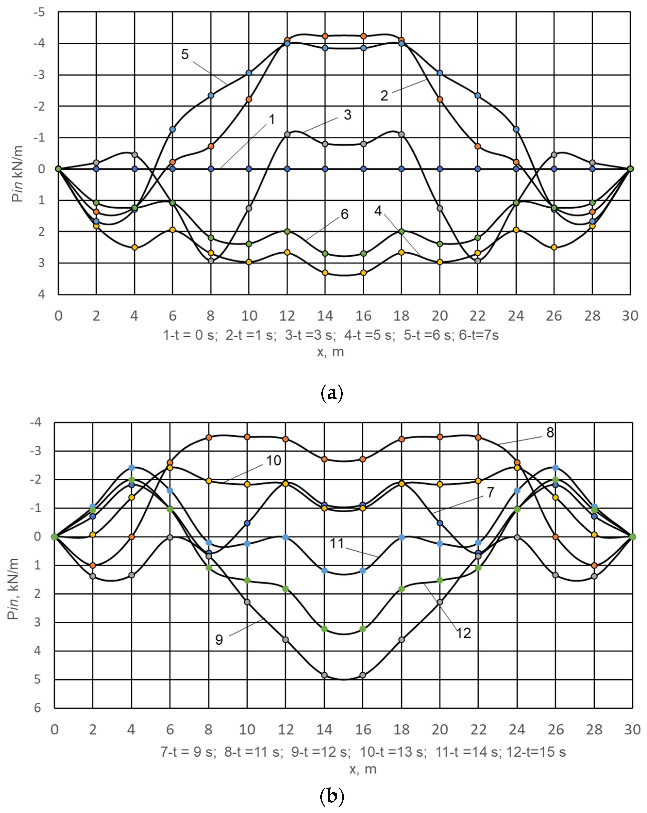
Let us discuss the results obtained and presented in Figure 3 and Figure 4. These calculations were performed, and the results are shown in Figure 5. The numerical values of the distributed total inertia force during diesel fuel pumping are presented as graphs in Figure 3a,b.
At the moment t = 0   s , there is no inertial force (Figure 3a, curve 1). Further, at t > 0   s , the force of inertia appears P i n . At t = 1   s (curve 2), this force for most of the length of the beam transition is directed upward with respect to the abscissa axis X. At t = 5   s (curve 4 in Figure 3a), the indicated force is completely directed downward, i.e., at change in time, the direction of the force of inertia also changes. A similar picture is shown in Figure 3b. As can be seen from Figure 3a,b, the force of inertia, as in the case of displacements, is symmetrical about the middle of the beam transition ( x = 15   m ) . The most significant value of the force of inertia calculated and shown in Figure 3 is equal to 4.840   k N / m (curve 9, t = 12   s ). If we take into account the full range of time changes ( 0 t 47   s ), for which the force of inertia was calculated, then the most significant positive value of the force of inertia corresponds to the time t = 17   s   ( P i n = 5.754   k N / m ). The most significant negative value by module occurs at the moment of time t = 33   s   ( P i n = 5.009   k N / m ). These values exceed the total static forces by modulo, respectively q 1 and q 2 1.935 times and 1.685 times. Considering all of the above, we can assert that the cause of oscillations in the vertical plane of the oil pipeline axis with time-varying and unequal deviations up and down relative to the abscissa axis is the inertial forces P i n arising from the movement of the oil product in the pipeline.
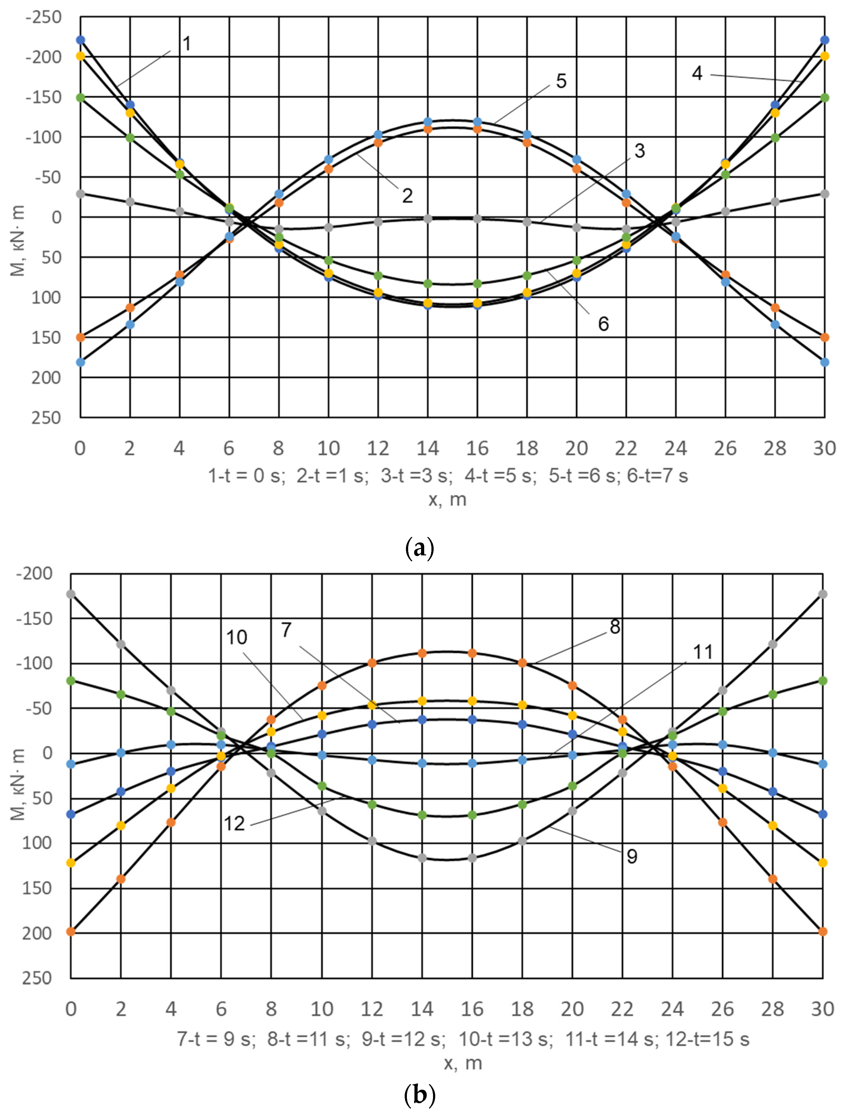
Figure 4 shows the graphs of bending moments of the pipes of the oil pipeline beam transition caused by static forces q 1 and q 2 and the total force of inertia P i n . Curve 1 ( t = 0   s ) in Figure 4a shows the bending moment due to the forces q 1 i q 2 . This moment is positive in the middle part of the beam length (approximately at 6 < x < 24 m) and negative about 6 > x > 24 m. At t = 1   s (curve 2, Figure 4a), the bending moment is negative in the middle part of the beam transition and positive outside the middle part of the beam transition. The same can be said for any of the bending moment curves shown in Figure 4a,b. The exception is curve 11 for t = 14   s (Figure 4b). In this case, the bending moment is three times positive and two times negative along the entire length of the crossing.
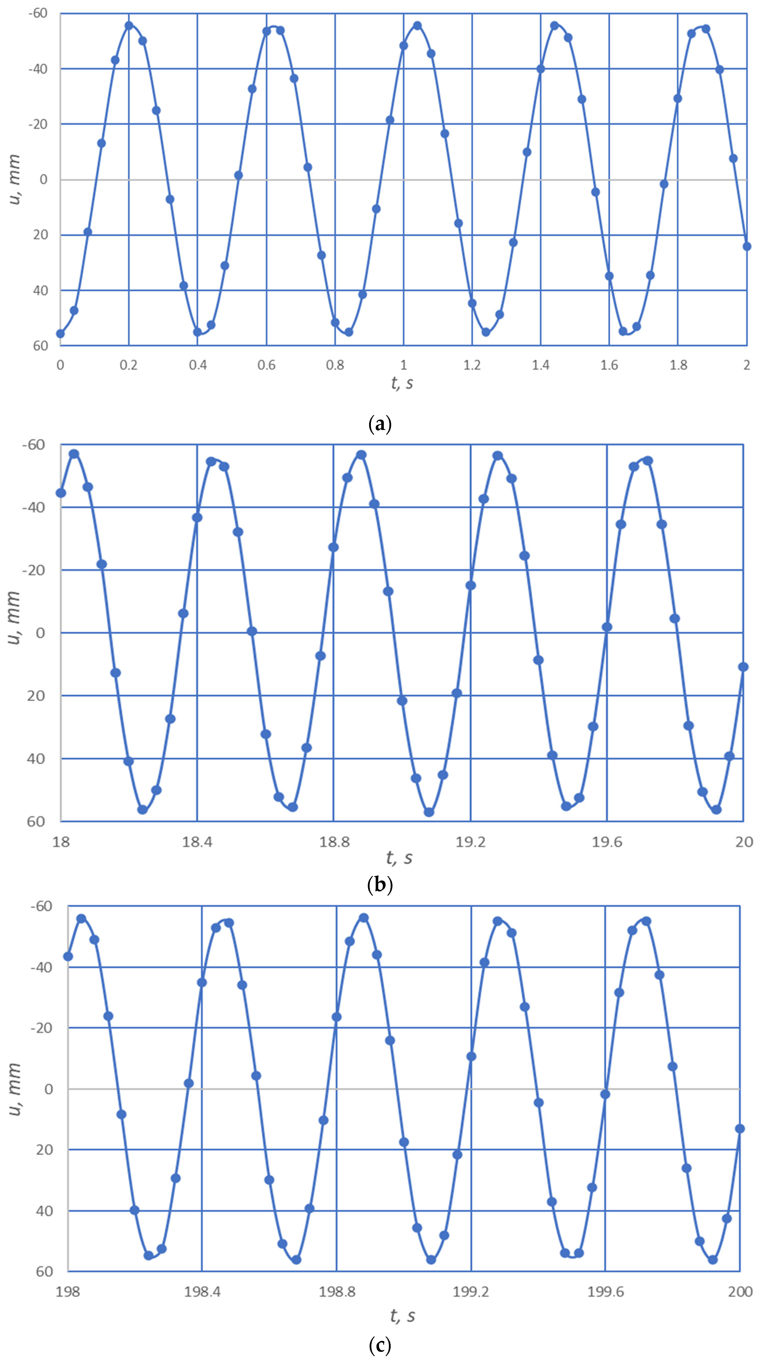
Figure 5 shows the results of calculating the displacements of the axis point of the oil pipeline beam transition in its middle section ( x = 15   m ) depending on the time, performed in small increments ( t = 0.01   s ), in different time ranges: 0 t 2   s (Figure 5a), 18 t 20   s (Figure 5b), 198   t 200   s (Figure 5c). It turned out that the forced oscillations of the pipeline at the oil pipeline beam crossing when pumping diesel fuel are periodic with the maximum deviation from the abscissa axis up and down equal to A 57   m m and period t Π 0.415   s . In the paper, the period of oscillation of the oil pipeline was determined by the graph-analytical method from Figure 5 and was approximated. The period of oscillation can also be determined analytically by the expression:
t Π = 2 π 1 L 2 g E I q 1 + q 2 L C M ( λ 1 2 , , λ 10 2 )   ,
where LCM—least common multiple. Values A i t Π are obtained from the results of the calculations. Finally, Figure 6 shows the bending moments at the transition as a function of its coordinate for the time t = 0 ; 0.2 ; 0.64 ; 0.84   s . Curves 1 and 4 and curves 2 and 3 practically coincide. This is because the time interval between these curves is close to an integer number of periods t Π . Some discrepancy is due to the approximate value of t Π . This result once again confirms the fact that the oil pipeline fluctuates periodically at the girder crossing.
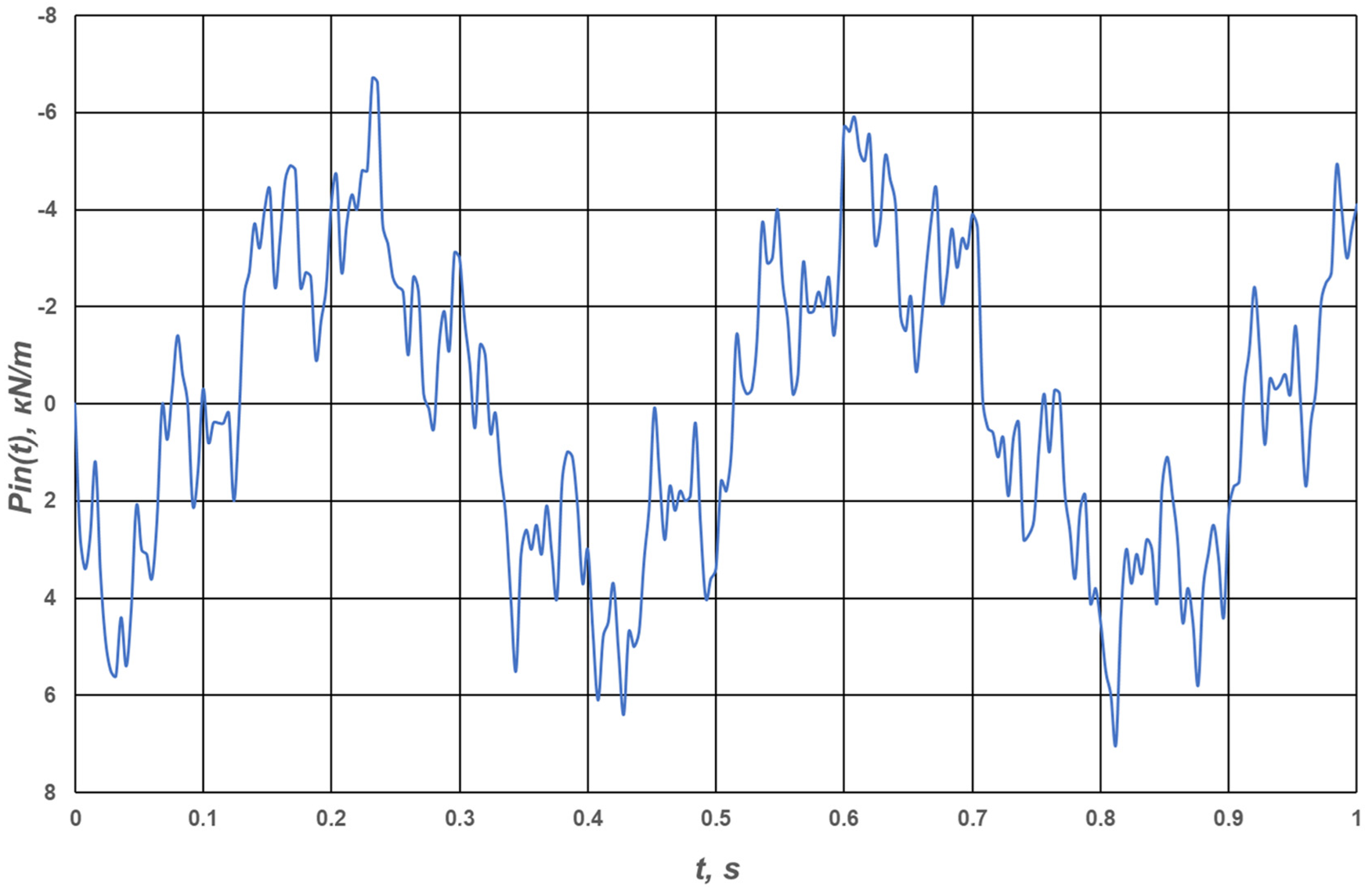
Given the large amount of graphic material presented, the forces of inertia on periodicity were not investigated. Only the calculation of inertial forces as a function of time in the range of 0 t 1   s (Figure 7) in increments of t = 0.001   s , and the graph is plotted in increments of t = 0.01   s . Since the graph is built for 250 values out of 1000 calculated, it does not accurately reflect the true picture of dependence P i n t .

4. Discussion

The authors of this article have not found a single scientific publication for the period from 2019 to 2024 that would consider the impact of inertia on the operation of oil pipelines. This indicates the relevance of the problem raised by the authors both today and in the near future. All kinds of information related to the transportation of oil products by pipelines laid both on land and in the sea depths is important. Progress in addressing any specific challenge related to the transportation of oil products can provide a foundation for tackling more complex problems in this field.
Researchers Peng et al. [95] note that pipelines are sensitive to oil and gas leaks during long-distance transportation. This may be due to damage to the pipeline by external forces, a long time of operation of the pipeline, etc. Existing technologies are time-consuming and costly to detect leaks. The authors propose a shock-based approach based on MobileNet V2. The effect of pipe leaks on vibration characteristics was determined. The improved MobileNet V2 model was used to classify the Mela spectrogram. The improved model shows good results. Akande et al. [96] investigate the interaction of oil and gas vibration sensors with unmanned aerial vehicles for a pipeline leak detection system (LDS) with a short response time. Several serious accidents have occurred, including human casualties, environmental pollution, and significant material costs, most of which were caused by untimely detection of leaks from pipes in oil and gas transportation systems. Comparative analysis of the response time of the newly developed LDS and existing systems is more than 11 times less than the time of the existing warning system.
Researchers Park and Liang [97] note that oil and gas pipeline steels and welds are subjected to a variety of cyclic loads. A better understanding of the impact of fatigue test parameters and fatigue behavior of pipeline steel and welds is needed. In this study, the effect of fatigue parameters on the Paris Law coefficients for pipeline steel and welds was investigated.
Subsea pipelines are critical to offshore oil and gas production. However, they are vulnerable to vortex vibration (VIV) and simultaneous localized scratches, which threaten the integrity of the pipeline. Yan et al. [98], an experimental study of VIV suppression for subsea multi-span pipelines was conducted by attaching screw rods to the pipeline. The maximum VIV suppression efficiency exceeded 90%, and the study by Liang et al. [99] established the relationship between vibration caused by vortex motion and local scour using Flow-3D in the case of two tandem pipelines. It is shown that in the case of a small horizontal gap between the pipelines, one scour pit is formed, and when this gap increases, two independent scour pits are formed.
The article by Tang et al. [100] is devoted to the problems that arise when laying oil and gas pipelines in areas with soft soils and describes ways to overcome them, and the paper by Wang et al. [101] discusses the change in the engineering properties of permafrost, the pipeline foundation, and its impact on the mechanical behavior of the pipeline. The distribution of soil temperature around a buried warm pipeline is investigated. It is shown that significant stresses will occur at the boundary of weak and strong thawing of permafrost. After a certain period of operation of such pipelines, their destruction is possible.
This proves once again that ensuring the integrity of pipelines during their operation is extremely important for pipeline transportation of oil and gas. In the study by Wang et al. [102], the authors note that for long oil and gas pipelines, it is necessary to perform ring welds in the field. This inevitably leads to defects in them. Therefore, this study proposes an artificial neural network model to predict the risk of failure of welds with defects. This study is a valuable reference for pipeline operators to prevent pipeline accidents. And in two other papers, Zhang et al. [103] and Li et al. [104] consider typical geological disasters of localized subsidence of the soil layer for buried main oil and gas pipelines. The first of these papers, based on the results of large-scale model tests, established the following: first, the height of soil subsidence has a relatively greater impact on the deformation of pipes and soil pressure on them than the range of subsidence; second, an increase in the moisture content of the backfill soil leads to a decrease in pipeline deformation and soil pressure on them. The second paper proposes a stress monitoring system that is guided by an algorithm for solving the strain–stress relationship. This monitoring technology implements early warning of geohazards.
The researchers pay special attention to the strength of steel pipelines as the main elements of oil and gas pipeline transportation. The article by Arumungan et al. [105] explicitly states that steel pipelines are the most important element of oil and gas pipeline transportation, but they are subject to corrosion damage despite all measures to protect them from corrosion. The combination of corrosion defects and various external loads leads to a decrease in their fracture pressure, which is especially significant in the bending areas of pipes as the weakest links in the pipeline. The main purpose of the study by Witek [106] was to assess the bursting pressure and structural integrity of a steel pipeline based on the results of an in-situ inspection. Particular attention is paid to the results of diagnostics using axial excitation magnetic flux scattering technology. The residual strength was assessed according to the recommendations of Det Norske Veritas. And in the study by Zhang et al. [107], they used a network algorithm for fuzzy deep learning to form a maintenance scheme for an underwater pipeline and ensure its safe operation. The factors of the marine environment that affect the corrosion of subsea pipelines are taken into account, and a reliability model for a corroded subsea pipeline is found. A fuzzy network algorithm is used to calculate the probability of failure of a rusty pipeline.
Based on the proceedings of the International Conference on Marine Mechanics and Arctic Engineering, Saraswat et al. [108] are devoted to the identification of free spans in a subsea pipeline. A free span can be single or multi-span, which is analogous to single and multi-span girder crossings of aboveground sections of main pipelines. Underwater currents cause vibrations of free spans of underwater pipelines, which is harmful to the pipeline, especially for welds, as it causes fatigue of the pipeline material and leads to a decrease in its durability. The paper refers to the developed practical materials that outline the methodology for assessing the fatigue of the material of free-running pipelines.
The study by Liu et al. [109] indicates that ground collapse is one of the main geological disasters affecting the safe operation of oil and gas pipelines. In this work, a finite element geometric model of the interaction between soil and pipeline during a ground collapse was created. Analyzing the results of using this model, a reference value for the maximum subsidence deformation of the pipeline during a ground collapse is proposed. The work is of practical value for pipeline monitoring, early warning and disaster management.
The study of Bao et al. [110] set certain vibrations and found the transient characteristics of two-phase gas-liquid flow in inclined pipes. It was found that inclined vibration has the most significant effect on gas-liquid flow, followed by horizontal and vertical vibration. The effect of vibration on the secondary flow increases with increasing vibration amplitude. This study has practical applications in offshore oil and gas equipment.
The publication of Chudyk et al. [111,112] found the relationships between the parameters of unsteady longitudinal and torsional vibrations of a drilling tool and developed a mathematical model to study their properties. As a result of solving this problem, it became possible to select the optimal modes of dynamic loading of a drilling tool in order to increase its energy efficiency. This indicates the importance of studying the vibrations that accompany various technological processes. The same conclusion is confirmed by Moysyshyn et al. [113], in which experimental studies of the drilling process on a drilling rig made it possible to provide practical recommendations for reducing the harmful effects of drilling tool vibration and reducing the energy intensity of the drilling process. In the author’s problem, an increase in the oscillations of the oil pipeline axis when pumping one of the oil products causes an increase in the values of bending moments. This means that these vibrations are harmful to the technological process. They are caused by internal forces, namely, the forces of inertia that occur during the operation of the pipeline. The study of these vibrations is necessary to ensure that they can be reduced, as well as to perform calculations of the pipeline for strength and stability.
Summarizing all of the above in relation to the cited literature, it should be noted that in the last five years, a significant number of scientific publications have appeared related to the problems of transportation of oil products by oil pipelines laid not only on land but also by subsea pipelines laid on the seabed. While vibrations (oscillations) of submarine pipelines are caused by underwater currents, i.e., external forces with respect to the pipelines themselves, oscillations of above-ground sections of the oil pipeline on land are caused by internal forces, namely, inertial forces. The latter has yet to be studied.

5. Conclusions

When pumping diesel fuel through a beam transition of an oil pipeline and taking into account the component of the inertia forces of the oil product, which does not depend on the speed of its movement, and the inertia force of the pipeline itself, which are equally directed, it was found that in the vertical plane, where the pipeline axis is located at the transition, there are familiarly variable, unattenuated oscillations of the axis of the beam transition, which continuously change in time and are symmetrical relative to the middle of the length of the beam transition. The midline section at the transition corresponds to the largest deviation of the pipeline axis compared to all other sections along the length relative to the abscissa axis.
The reason for these fluctuations is the inertial forces taken into account. When taking into account the full range of time changes ( 0 < t 47   s ), for which the total force of inertia was calculated in steps t = 1   s , then the largest positive value of the force of inertia corresponds to the moment of time t = 17   s and equals 5.754   k N / m , and the largest negative value by module occurs at the moment of time t = 33   s and equals 5.009   k N / m . These values exceed the total static forces by 1.935 times and 1.685 times.
When calculating the displacements of the oil pipeline axis points in increments of t = 0.01   s in different time ranges from 0 to 200 s, a result was obtained indicating that the oscillation of the oil pipeline axis at the transition is periodic and symmetrical with respect to the abscissa axis.
The period of these oscillations was found to be approximately equal to t Π = 0.415   s and the maximum deviation from the abscissa axis ( u 57   m m ).
Changes in bending moments are also periodic. This is confirmed by the results of the calculations performed. The bending moments calculated for time points that are offset by an integer number of periods practically coincide. Some discrepancies are explained by the approximate value of the found oscillation period.
This study did not take into account the other two components of the inertia force on the deflection of the oil pipeline axis and its bending moments at the beam transition, namely, the Coriolis and centrifugal inertia forces. Accounting for these forces will be the goal of our further research in this area.

Author Contributions

Conceptualization, R.T.; methodology, R.T. and V.L.; validation, R.T. and V.L.; formal analysis, R.T.; investigation, R.T.; resources, R.T. and V.L.; data curation, R.T.; writing—original draft preparation, R.T.; writing—review and editing, R.T. and V.L.; visualization, R.T.; supervision, R.T. and V.L.; project administration, R.T. and V.L.; funding acquisition, V.L. All authors have read and agreed to the published version of the manuscript.

Funding

The presented results have been partly obtained within the framework of the research works, state registration No. 0123U100985 and No. 0124U000473 funded by the Ministry of Education and Science of Ukraine.

Data Availability Statement

The original contributions presented in this study are included in the article. Further inquiries can be directed to the corresponding author.

Acknowledgments

The authors are grateful for the help in statistical data processing to Vasyl Protsiuk, Department of Applied Programming and Computing, Ivano-Frankivsk National Technical University of Oil and Gas. The authors express their sincere gratitude for the thorough consultations provided by Lyubomyr Ropiak, Department of Computerized Mechanical Engineering, Ivano-Frankivsk National Technical University of Oil and Gas. The authors express their sincere gratitude and respect to the Armed Forces of Ukraine, who made it possible to complete the preparation of this article for publication. The team of authors express their gratitude to the reviewers for valuable recommendations that have been taken into account to significantly improve the quality of this paper.

Conflicts of Interest

The authors declare no conflicts of interest.

References

  1. Andrusiv, U.; Zelinska, H.; Galtsova, O.; Kupalova, H.; Goncharenk, N. The modeling and forecasting of fuel and energy resources usage in the context of the energy independence of Ukraine. Polityka Energ. 2021, 24, 29–47. [Google Scholar] [CrossRef]
  2. Zelinska, H.; Fedorovych, I.; Andrusiv, U.; Chernova, O.; Kupalova, H. Modeling and prediction of the gas pipelines reliability indicators in the context of energy security of Ukraine. CEUR Workshop Proc. 2020, 2713, 415–433. [Google Scholar]
  3. He, Z.; He, L.; Liu, H.; Wang, D.; Li, X.; Li, Q. Experimental and Numerical Study on Gas-Liquid Flow in Hilly-Terrain Pipeline-Riser Systems. Discrete Dyn. Nat. Soc. 2021, 2021, 5529916. [Google Scholar] [CrossRef]
  4. Hart, J.D.; Zulfiqar, N. Historical Perspective on Wind-Induced Vibration of Above-Ground Pipeline Configurations on the Alaskan North Slope. Proc. Biennial Int. Pipeline Conf. 2024, 2A, v02AT03A030. [Google Scholar] [CrossRef]
  5. Xu, W.; He, Z.; Zhai, L.; Wang, E. Vortex-induced vibration prediction of an inclined flexible cylinder based on machine learning methods. Ocean Eng. 2023, 282, 114956. [Google Scholar] [CrossRef]
  6. Satchithananthan, U.; Ullah, S.N.; Lee, F.H.; Chen, Z.; Gu, H. Centrifuge modeling of axial pipe-soil interaction of deep-water pipelines. Geotech. Test. J. 2020, 43, 94–112. [Google Scholar] [CrossRef]
  7. Pukish, A.; Mandryk, O.; Arkhypova, L.; Syrovets, S.; Hryniuk, D. Mathematical modeling of pollution of underground aquifers due to mining of minerals. Min. Miner. Depos. 2024, 18, 94–103. [Google Scholar] [CrossRef]
  8. Bazaluk, O.; Slabyi, O.; Vekeryk, V.; Velychkovych, A.; Ropyak, L.; Lozynskyi, V. A Technology of Hydrocarbon Fluid Production Intensification by Productive Stratum Drainage Zone Reaming. Energies 2021, 14, 3514. [Google Scholar] [CrossRef]
  9. Kubba, A.; Trabelsi, H.; Derbel, F. Enhanced Long-Range Network Performance of an Oil Pipeline Monitoring System Using a Hybrid Deep Extreme Learning Machine Model. Future Internet 2024, 16, 425. [Google Scholar] [CrossRef]
  10. Han, J.; Tian, L. Review of Construction Technology of Advanced Energy Infrastructure. Energies 2024, 17, 4157. [Google Scholar] [CrossRef]
  11. Popescu, C.; Gabor, M.R. Quantitative Analysis Regarding the Incidents to the Pipelines of Petroleum Products for an Efficient Use of the Specific Transportation Infrastructure. Processes 2021, 9, 1535. [Google Scholar] [CrossRef]
  12. Dai, L.; Wang, D.; Wang, T.; Feng, Q.; Yang, X. Analysis and Comparison of Long-Distance Pipeline Failures. J. Pet. Eng. 2017, 2017, 3174636. [Google Scholar] [CrossRef]
  13. Xie, M.; Tian, Z. A review on pipeline integrity management utilizing in-line inspection data. Eng. Fail. Anal. 2018, 92, 222–239. [Google Scholar] [CrossRef]
  14. Dutkiewicz, M.; Andrusyak, A.; Kychma, A.; Vytvytskyi, V.; Velychkovych, A. Numerical model of interaction of a mobile lift chain with a main gas pipeline pipe in the process of repair work. Ekspl. Niezawodn. 2024, 26, 187159. [Google Scholar] [CrossRef]
  15. Prysyazhnyuk, P.; Bembenek, M.; Drach, I.; Korzhov, A.; Romanyshyn, L.; Ropyak, L. Restoration of the Impact Crusher Rotor Using FCAW with High-Manganese Steel Reinforced by Complex Carbides. Manag. Syst. Prod. Eng. 2024, 32, 294–302. [Google Scholar] [CrossRef]
  16. Bembenek, M.; Mandziy, T.; Ivasenko, I.; Berehulyak, O.; Vorobel, R.; Slobodyan, Z.; Ropyak, L. Multiclass Level-Set Segmentation of Rust and Coating Damages in Images of Metal Structures. Sensors 2022, 22, 7600. [Google Scholar] [CrossRef]
  17. Shats’kyi, I.P. Closure of a longitudinal crack in a shallow cylindrical shell in bending. Mater. Sci. 2005, 41, 186–191. [Google Scholar] [CrossRef]
  18. Shats’kyi, I.P.; Makoviichuk, M.V. Analysis of the limiting state of cylindrical shells with cracks with regard for the contact of crack lips. Strength Mater. 2009, 41, 560–565. [Google Scholar] [CrossRef]
  19. Okodi, A.; Li, Y.; Cheng, R.; Kainat, M.; Yoosef-Ghodsi, N.; Adeeb, S. Crack Propagation and Burst Pressure of Pipeline with Restrained and Unrestrained Concentric Dent-Crack Defects Using Extended Finite Element Method. Appl. Sci. 2020, 10, 7554. [Google Scholar] [CrossRef]
  20. Zvirko, O.I.; Savula, S.F.; Tsependa, V.M.; Gabetta, G.; Nykyforchyn, H.M. Stress corrosion cracking of gas pipeline steels of different strength. Procedia Struct. Integr. 2016, 2, 509–516. [Google Scholar] [CrossRef]
  21. Shatskii, I.P.; Makoviichuk, N.V. Effect of closure of collinear cracks on the stress-strain state and the limiting equilibrium of bent shallow shells. J. Appl. Mech. Tech. Phys. 2011, 52, 464–470. [Google Scholar] [CrossRef]
  22. Dutkiewicz, M.; Dalyak, T.; Shatskyi, I.; Venhrynyuk, T.; Velychkovych, A. Stress Analysis in Damaged Pipeline with Composite Coating. Appl. Sci. 2021, 11, 10676. [Google Scholar] [CrossRef]
  23. Shatskyi, I.; Makoviichuk, M.; Ropyak, L.; Velychkovych, A. Analytical Model of Deformation of a Functionally Graded Ceramic Coating under Local Load. Ceramics 2023, 6, 1879–1893. [Google Scholar] [CrossRef]
  24. Ropyak, L.; Shihab, T.; Velychkovych, A.; Dubei, O.; Tutko, T.; Bilinskyi, V. Design of a Two-Layer Al–Al2O3 Coating with an Oxide Layer Formed by the Plasma Electrolytic Oxidation of Al for the Corrosion and Wear Protections of Steel. Prog. Phys. Met. 2023, 24, 319–365. [Google Scholar] [CrossRef]
  25. Tutko, T.; Dubei, O.; Ropyak, L.; Vytvytskyi, V. Determination of Radial Displacement Coefficient for Designing of Thread Joint of Thin-Walled Shells. In Advances in Design, Simulation and Manufacturing IV, Proceedings of the 4th International Conference on Design, Simulation, Manufacturing: The Innovation Exchange, DSMIE 2021, Lviv, Ukraine, 8–11 June 2021; Lecture Notes in Mechanical Engineering; Springer: Cham, Switzerland, 2021; pp. 153–162. [Google Scholar] [CrossRef]
  26. Vynnykov, Y.; Kharchenko, M.; Manhura, S.; Aniskin, A.; Manhura, A. Neural network analysis of safe life of the oil and gas industrial structures. Min. Miner. Depos. 2024, 18, 37–44. [Google Scholar] [CrossRef]
  27. Matkivskyi, S. Near Wellbore Heavy Hydrocarbons Retrograde Condensation Study. Miner. Resour. Ukr. 2023, 3, 39–44. [Google Scholar] [CrossRef]
  28. Raimbekova, A.; Kapralova, V.; Dalbanbai, A.; Kubekova, S.; Popova, A. Effect of Various Phosphate Inhibitors on Corrosion of Low Carbon Steel in 3% Sodium Chloride Solution. Eng. J. Satbayev Univ. 2023, 145, 25–31. [Google Scholar] [CrossRef]
  29. Tatsiy, R.M.; Pazen, O.Y.; Vovk, S.Y.; Ropyak, L.Y.; Pryhorovska, T.O. Numerical study on heat transfer in multilayered structures of main geometric forms made of different materials. J. Serb. Soc. Comput. Mech. 2019, 13, 36–55. [Google Scholar] [CrossRef]
  30. Hamzawy, N.; Khedr, M.; Mahmoud, T.S.; EI-Mahallawi, I.; Khalifa, T.A. Investigation of Temperature Variation During Friction Drilling of 6082 and 7075 Al-Alloys. In Light Metal Technology symposium, Proceedings of the Light Metals Symposium, 149th Annual Meeting and Exhibition, TMS 2020, San Diego, CA, USA, 23–27 February 2020; Springer: Cham, Switzerland, 2020; pp. 471–477. [Google Scholar] [CrossRef]
  31. Doroshenko, Y.; Kogut, G.; Doroshenko, Y.; Tarayevs’kyy, O.; Pyrig, T. Numerical study on erosion wear and strength of main gas pipelines bends. Stroj. Cas. 2021, 71, 27–40. [Google Scholar] [CrossRef]
  32. Owoseni, O.D.; Orolu, K.O.; Oyediran, A.A. Dynamics of Slightly Curved Pipe Conveying Hot Pressurized Fluid Resting on Linear and Nonlinear Viscoelastic Foundations. J. Vib. Acoust. 2018, 140, 021005. [Google Scholar] [CrossRef]
  33. Kryzhanivs’kyi, E.I.; Rudko, V.P.; Shats’kyi, I.P. Estimation of admissible loads upon a pipeline in the zone of sliding ground. Mater. Sci. 2004, 40, 547–551. [Google Scholar] [CrossRef]
  34. Shats’kyi, I.P.; Struk, A.B. Stressed state of pipeline in zones of soil local fracture. Strength Mater. 2009, 41, 548–553. [Google Scholar] [CrossRef]
  35. Vazouras, P.; Dakoulas, P.; Karamanos, S.A. Pipe–soil interaction and pipeline performance under strike–slip fault movements. Soil Dyn. Earthq. Eng. 2015, 72, 48–65. [Google Scholar] [CrossRef]
  36. Han, J.; Bi, Y.; Hou, B.; Zhao, W.; El Naggar, M.H. Response of Corroded Steel Pipeline Without and with CFRP Reinforcement to Reverse Fault Movement. Appl. Sci. 2024, 14, 10896. [Google Scholar] [CrossRef]
  37. Landar, S.; Velychkovych, A.; Ropyak, L.; Andrusyak, A. A Method for Applying the Use of a Smart 4 Controller for the Assessment of Drill String Bottom-Part Vibrations and Shock Loads. Vibration 2024, 7, 802–828. [Google Scholar] [CrossRef]
  38. Filippov, A.N. Dynamic impact on a pipeline considering dry friction on its surface. Mech. Solids 2019, 54, 1144–1150. [Google Scholar] [CrossRef]
  39. Shatskyi, I.; Perepichka, V.; Vaskovskyi, M. Longitudinal waves in an elastic rod caused by sudden damage to the foundation. Theor. Appl. Mech. 2021, 48, 29–37. [Google Scholar] [CrossRef]
  40. Shatskyi, I.; Makoviichuk, M.; Vaskovkyi, M. Transversal Straining of Pressurized Pipeline Caused by Vibration of Damaged Foundation. Springer Proc. Math. Stat. 2024, 453, 501–508. [Google Scholar] [CrossRef]
  41. Zhang, Y.; Ye, J.; He, K.; Chen, S. Seismic Dynamics of Pipeline Buried in Dense Seabed Foundation. J. Mar. Sci. Eng. 2019, 7, 190. [Google Scholar] [CrossRef]
  42. Shatskii, I.P.; Perepichka, V.V. Shock-wave propagation in an elastic rod with a viscoplastic external resistance. J. Appl. Mech. Techn. Phys. 2013, 54, 1016–1020. [Google Scholar] [CrossRef]
  43. Moisyshyn, V.; Levchuk, K. Investigation on Releasing of a Stuck Drill String by Means of a Mechanical Jar. Oil Gas Sci. Technol. 2017, 72, 27–35. [Google Scholar] [CrossRef]
  44. Shatskyi, I.; Perepichka, V. Problem of dynamics of an elastic rod with decreasing function of elastic-plastic external resistance. In Dynamic Systems and Applications, Proceedings of the DSTA 2017, Łódź, Poland, 11–14 December 2017; Springer: Cham, Switzerland, 2018; Volume 249, pp. 335–342. [Google Scholar] [CrossRef]
  45. Begmatov, A.; Mamatova, N. Impact of rigid body and viscous-plastic rod of finite length. E3S Web of Conf. 2023, 401, 02003. [Google Scholar] [CrossRef]
  46. Bembenek, M.; Grydzhuk, Y.; Gajdzik, B.; Ropyak, L.; Pashechko, M.; Slabyi, O.; Al-Tanakchi, A.; Pryhorovska, T. An Analytical-Numerical Model for Determining “Drill String–Wellbore” Frictional Interaction Forces. Energies 2024, 17, 301. [Google Scholar] [CrossRef]
  47. Shatskyi, I.; Perepichka, V. Shock Torsion Wave in an Elastic Rod with Decreasing Function of Viscoplastic External Friction. Springer Proc. Math. Stat. 2024, 454, 585–592. [Google Scholar] [CrossRef]
  48. Bolonnyi, V.T.; Grudz, V.Y.; Grudz, Y.V.; Zapukhliak, V.B.; Dodyk, T.Y. Prediction of transient processes in oil pipelines with the purpose of emergency incident prevention. Nauk. Visn. Nats. Hirn. Univ. 2020, 1, 118–122. [Google Scholar] [CrossRef]
  49. Petryna, D.Y.; Kozak, O.L.; Shulyar, B.R.; Petryna, Y.D.; Hredil, M.I. Influence of alloying by rare-earth metals on the mechanical properties of 17g1s pipe steel. Mater. Sci. 2013, 48, 575–581. [Google Scholar] [CrossRef]
  50. Melnychenko, Y.; Poberezhny, L.; Hrudz, V.; Zapukhliak, V.; Chudyk, I.; Dodyk, T. Determination of preconditions leading to critical stresses in pipeline during lowering. In Degradation Assessment and Failure Prevention of Pipeline Systems; Lecture Notes in Civil Engineering; Springer: Cham, Switzerland, 2021; Volume 102, pp. 241–252. [Google Scholar] [CrossRef]
  51. Andreikiv, O.E.; Skal’s’kyi, V.R.; Dolins’ka, I.Y.; Dzyubyk, A.R. Influence of Corrosive Hydrogenating Media on the Residual Service Life of Structural Elements in the Maneuvering Mode of Operation. Mater. Sci. 2018, 54, 61–68. [Google Scholar] [CrossRef]
  52. Voloshyn, V.A.; Zvirko, O.I.; Sydor, P.Y. Influence of the compositions of neutral soil media on the corrosion cracking of pipe steel. Mater. Sci. 2015, 50, 44–47. [Google Scholar] [CrossRef]
  53. Kharchenko, L.E.; Kunta, O.E.; Zvirko, O.I.; Savula, R.S.; Duryahina, Z.A. Diagnostics of hydrogen macrodelamination in the wall of a bent pipe in the system of gas mains. Mater. Sci. 2016, 51, 530–537. [Google Scholar] [CrossRef]
  54. Khoma, M.; Vynar, V.; Chuchman, M.; Vasyliv, C. Corrosion-mechanical failure of pipe steels in hydrogen sulfide environments. In Degradation Assessment and Failure Prevention of Pipeline Systems; Lecture Notes in Civil Engineering; Springer: Cham, Switzerland, 2021; Volume 102, pp. 231–239. [Google Scholar] [CrossRef]
  55. Khoma, M.S.; Korniy, S.A.; Vynar, V.A.; Datsko, B.M.; Maksishko, Y.Y.; Dykha, O.V.; Bukliv, R.L. Influence of Hydrogen Sulfide on the Carbon-Dioxide Corrosion and the Mechanical Characteristics of High-Strength Pipe Steel. Mater. Sci. 2022, 57, 805–812. [Google Scholar] [CrossRef]
  56. Andreikiv, O.Y.; Dolins’ka, I.Y.; Shtoiko, I.P.; Raiter, O.K.; Matviiv, Y.Y. Evaluation of the Residual Service Life of Main Pipelines with Regard for the Action of Media and Degradation of Materials. Mater. Sci. 2019, 54, 638–646. [Google Scholar] [CrossRef]
  57. Vorobel, R.; Student, O.; Ivasenko, I.; Maruschak, P.; Krechkovska, H.; Zvirko, O.; Berehulyak, O.; Mandziy, T.; Tsybailo, I.; Solovei, P. Development of a method for computer processing of fractographic images to assess the cohesion of inclusions to the matrix in the weld metal after its operational degradation and hydrogenation. Materialia 2024, 34, 102074. [Google Scholar] [CrossRef]
  58. Mandziy, T.; Ivasenko, I.; Berehulyak, O.; Vorobel, R. Influence of Colour Restoration on Rust Image Segmentation. In Proceedings of the IEEE UKRCON 2021. 3rd Ukraine Conference on Electrical and Computer Engineering, Lviv, Ukraine, 26–28 August 2021; IEEE: Washington, DC, USA, 2021; pp. 68–73. [Google Scholar] [CrossRef]
  59. Stetsiuk, S.; Bondarenko, R.; Doroshenko, Y.; Holubenko, V. Experimental Studies on the Dynamics of the Movement of Cleaning Pigs through Tee Pipe Fittings. Stroj. Casopis. 2024, 74, 9–24. [Google Scholar] [CrossRef]
  60. Stetsiuk, S.; Shatskyi, I.; Doroshenko, Y.; Velychkovych, A. Analytical Study of Frictional Interaction of Elastic Cleaning Pig with Pipeline Wall. Arch. Mater. Sci. Eng. 2024, 129, 67–76. [Google Scholar] [CrossRef]
  61. Amandi, K.U.; Diemuodeke, E.O.; Briggs, T.A.; Pham, D. Model for remaining strength estimation of a corroded pipeline with interacting defects for oil and gas operations. Cogent Eng. 2019, 6, 1663692. [Google Scholar] [CrossRef]
  62. Vanitha, C.N.; Easwaramoorthy, S.V.; Krishna, S.A.; Cho, J. Efficient qualitative risk assessment of pipelines using relative risk score based on machine learning. Sci. Rep. 2023, 13, 14918. [Google Scholar] [CrossRef] [PubMed]
  63. Fan, T.; Liu, Z.; Li, M.; Zhao, Y.; Zuo, Z.; Guo, R. Development of cost-effective repair system for locally damaged long-distance oil pipelines. Constr. Build. Mater. 2022, 333, 127342. [Google Scholar] [CrossRef]
  64. Yu, J.; Chen, C.; Li, C. Safety analysis and emergency response of suspended oil and gas pipelines triggered by natural disasters. Sustainability 2022, 14, 17045. [Google Scholar] [CrossRef]
  65. Bazaluk, O.; Kuchyn, O.; Saik, P.; Soltabayeva, S.; Brui, H.; Lozynskyi, V.; Cherniaiev, O. Impact of Ground Surface Subsidence Caused by Underground Coal Mining on Natural Gas Pipeline. Sci. Rep. 2023, 13, 19327. [Google Scholar] [CrossRef]
  66. Nguyen, L.Q.; Le, T.T.T.; Nguyen, T.G.; Tran, D.T. Prediction of Underground Mining-Induced Subsidence: Artificial Neural Network Based Approach. Min. Miner. Depos. 2023, 17, 45–52. [Google Scholar] [CrossRef]
  67. Ding, Y.; Yang, H.; Xu, P.; Zhang, M.; Hou, Z. Coupling interaction of surrounding soil-buried pipeline and additional stress in subsidence soil. Geofluids 2021, 7941989. [Google Scholar] [CrossRef]
  68. Bazaluk, O.; Lozynskyi, V.; Falshtynskyi, V.; Saik, P.; Dychkovskyi, R.; Cabana, E. Experimental Studies of the Effect of Design and Technological Solutions on the Intensification of an Underground Coal Gasification Process. Energies 2021, 14, 4369. [Google Scholar] [CrossRef]
  69. Lozynskyi, V. Critical Review of Methods for Intensifying the Gas Generation Process in the Reaction Channel during Underground Coal Gasification (UCG). Min. Miner. Depos. 2023, 17, 67–85. [Google Scholar] [CrossRef]
  70. Petlovanyi, M.; Lozynskyi, V.; Saik, P.; Sai, K. Predicting the producing well stability in the place of its curving at the underground coal seams gasification. E3S Web Conf. 2019, 123, 01019. [Google Scholar] [CrossRef]
  71. Yu, H.; Li, S.; Wang, X. The Recent Progress China Has Made in the Backfill Mining Method, Part I: The Theory and Equipment of Backfill Pipeline Transportation. Minerals 2021, 11, 1274. [Google Scholar] [CrossRef]
  72. Petlovanyi, M.; Sai, K. Research into Cemented Paste Backfill Properties and Options for Its Application: Case Study from a Kryvyi Rih Iron-Ore Basin, Ukraine. Min. Miner. Depos. 2024, 18, 162–179. [Google Scholar] [CrossRef]
  73. Bazaluk, O.; Petlovanyi, M.; Zubko, S.; Lozynskyi, V.; Sai, K. Instability Asses during Underground Mining of Iron Ores. Minerals 2021, 11, 858. [Google Scholar] [CrossRef]
  74. Kopei, V.; Onysko, O.; Odosii, Z.; Pituley, L.; Goroshko, A. Investigation of the Influence of Tapered Thread Profile Accuracy on the Mechanical Stress, Fatigue Safety Factor and Contact Pressure. Lect. Notes Netw. Syst. 2021, 233, 177–185. [Google Scholar] [CrossRef]
  75. Kopei, V.; Onysko, O.; Barz, C.; Dašić, P.; Panchuk, V. Designing a Multi-Agent PLM System for Threaded Connections Using the Principle of Isomorphism of Regularities of Complex Systems. Machines 2023, 11, 263. [Google Scholar] [CrossRef]
  76. Velychkovych, A.; Andrusyak, A.; Pryhorowska, T.; Ropyak, L. Analytical model of oil pipeline overground transitions, laid in mountain areas. Oil Gas Sci. Technol. 2019, 74, 65. [Google Scholar] [CrossRef]
  77. Grudz, V.; Grudz, Y.; Pavlenko, I.; Liaposhchenko, O.; Ochowiak, M.; Pidluskiy, V.; Portechyn, O.; Iakymiv, M.; Włodarczak, S.; Krupińska, A.; et al. Ensuring the Reliability of Gas Supply Systems by Optimizing the Overhaul Planning. Energies 2023, 16, 986. [Google Scholar] [CrossRef]
  78. Bi, A.; Huang, S.; Zhang, Y.; Cao, Y. Reliability analysis of oil and gas pipelines based on step-down-stress testing in corrosive environments. Math. Probl. Eng. 2022, 4055779. [Google Scholar] [CrossRef]
  79. Chen, X.; Jeng, D.-S. Oscillatory Seabed Responses Around Two Pipelines in Tandem Under Combined Wave and Current Loading. Int. J. Offshore Polar Eng. 2022, 32, 321–329. [Google Scholar] [CrossRef]
  80. Soares, B.; Srinil, N. Capturing wake stiffness in wake-induced vibration of tandem cylinders. In Proceedings of the Int. Conf. Offshore Mech. Arctic Eng. (OMAE) 2020, Online, 3–7 August 2020; Volume 6A, p. V06AT06A011. [Google Scholar] [CrossRef]
  81. Dutkiewicz, M.; Velychkovych, A.; Andrusyak, A.; Petryk, J.; Kychma, A. Analytical model of an oil pipeline with a support of an overpass built in a mountainous area. Energies 2023, 16, 4464. [Google Scholar] [CrossRef]
  82. Dutkiewicz, M.; Shatskyi, I.; Martsynkiv, O.; Kuzmenko, E. Mechanism of casing string curvature due to displacement of surface strata. Energies 2022, 15, 5031. [Google Scholar] [CrossRef]
  83. Dey, S.; Tesfamariam, S. Structural performance of buried pipeline undergoing fault rupture in sand using Taguchi design of experiments. Soil Dyn. Earthq. Eng. 2022, 155, 107174. [Google Scholar] [CrossRef]
  84. Liu, E.; Li, W.; Cai, H.; Peng, S. Formation Mechanism of Trailing Oil in Product Oil Pipeline. Processes 2019, 7, 7. [Google Scholar] [CrossRef]
  85. Striletskyi, Y.; Ropyak, L.; Bandura, A. Method of oscillation excitation for investigation of inconsistency of coating deposition on long parts. Vibroeng. Procedia 2024, 57, 25–31. [Google Scholar] [CrossRef]
  86. Bandura, A.; Skaskiv, O. Analog of hayman’s theorem and its application to some system of linear partial differential equations. J. Math. Phys. Anal. Geom. 2019, 15, 170–191. [Google Scholar] [CrossRef]
  87. Bandura, A.; Skaskiv, O. Entire Functions of Bounded L-Index: Its Zeros and Behavior of Partial Logarithmic Derivatives. J. Complex Anal. 2017, 2017, 3253095. [Google Scholar] [CrossRef]
  88. Sheremeta, M.M.; Trukhan, Y.S. On a generalization of some Shah equation. Carpathian Math. Publ. 2024, 16, 259–266. [Google Scholar] [CrossRef]
  89. Sheremeta, M.M. Pseudostarlikeness and Pseudoconvexity of Multiple Dirichlet Series. Univ. J. Math. Appl. 2023, 6, 130–139. [Google Scholar] [CrossRef]
  90. Bandura, A.; Skaskiv, O.; Hural, I.; Shehda, L.; Smolovyk, L. Analytic functions in a unit polydisc: Conditions of directional boundedness of L-index for the sum of functions with directionally bounded L-index. J. Math. Sci. 2025, 288, 155–162. [Google Scholar] [CrossRef]
  91. Bandura, A.I.; Salo, T.M.; Skaskiv, O.B. Composition of entire function and analytic functions in the unit ball with a vanished gradient. Mat. Stud. 2024, 62, 132–140. [Google Scholar] [CrossRef]
  92. Gere, J.; Timoshenko, S. Mechanics of Materials. CL Engineering, 4th ed.; 912p, Available online: https://www.amazon.com/Mechanics-Materials-James-M-Gere/dp/0534934293 (accessed on 15 February 2025).
  93. Fridman, V. Theory of Elastic Oscillations. Equations and Methods; Springer Nature Pte Ltd.: Singapore, 2018. [Google Scholar] [CrossRef]
  94. Filippov, A. Oscillations of Mechanical Systems; Naukova Dumka: Kyiv, Ukraine, 1965. [Google Scholar]
  95. Peng, L.; Zhang, J.; Li, Y.; Du, G. A novel percussion-based approach for pipeline leakage detection with improved MobileNetV2. Eng. Appl. Artif. Intell. 2024, 133, 108537. [Google Scholar] [CrossRef]
  96. Akande, S.; Adetunla, A.; Olanrewaju, T.; Adeoye, A. UAV and Its Approach in Oil and Gas Pipeline Leakage Detection. J. Robot. 2021, 1300740. [Google Scholar] [CrossRef]
  97. Park, D.-Y.; Liang, J. Effects of Fatigue Parameters on Fatigue Crack Growth Rate of Pipe Steels and Girth Weld. J. Press. Vessel Technol. 2024, 146, 031701. [Google Scholar] [CrossRef]
  98. Yan, S.; Jia, K.; Xu, W.; Ma, Y. An experimental study on vortex-induced vibration suppression for submarine multispan pipelines. Ocean Eng. 2023, 271, 113678. [Google Scholar] [CrossRef]
  99. Liang, W.; Lou, M.; Fan, C.; Zhao, D.; Li, X. Coupling effects of vortex-induced vibration and local scour of double tandem pipelines in steady current. Ocean Eng. 2023, 286, 115495. [Google Scholar] [CrossRef]
  100. Tang, J.; Xu, J.; Zhou, D.; Huang, D.; Li, Y.; Chen, Z. Ground surface deformation caused by pipe jacking construction in a soft soil area: An experiment-based study. Buildings 2023, 13, 1628. [Google Scholar] [CrossRef]
  101. Wang, F.; Wu, G.; Chen, D.; Li, G.; Qian, Y.; Xi, F.; Wang, L. Mexanical response of a buried pipeline to permafrost trawing based on sequential coupling method. Atmosphere 2023, 14, 620. [Google Scholar] [CrossRef]
  102. Wang, K.; Zhang, M.; Guo, Q.; Ma, W.; Zhang, Y.; Wu, W. Failure risk prediction model for girth welds in high-strength steel pipeline based on historical data and artificial neural network. Processes 2023, 11, 2273. [Google Scholar] [CrossRef]
  103. Zhang, Y.; Hou, S.; Lin, L.; Lou, Y.; Zhou, Y. Experimental study on the mechanical behavior of buried steel pipeline subjected to the local subsidence. Int. J. Press. Vessels Piping 2023, 206, 105037. [Google Scholar] [CrossRef]
  104. Li, X.; Wu, Q.; Jin, H.; Kan, W. A new stress monitoring method for mechanical state of buried steel pipelines under geological hazards. Adv. Mater. Sci. Eng. 2022, 2022, 4498458. [Google Scholar] [CrossRef]
  105. Arumugam, T.; Vijaya Kumar, S.D.; Karuppanan, S.; Ovinis, M. The influence of axial compressive stress and internal pressure on a pipeline network: A review. Appl. Sci. 2023, 13, 3799. [Google Scholar] [CrossRef]
  106. Witek, M. Structural integrity of steel pipeline with clusters of corrosion defects. Materials 2021, 14, 852. [Google Scholar] [CrossRef]
  107. Zhang, W.; Zhang, J.; Li, X.; Chen, F.; Guo, J.; Li, W.; Cai, J. Energy pipeline strength evaluation and reliability technology based on fuzzy deep learning network algorithm. Energy Rep. 2022, 8, 5129–5136. [Google Scholar] [CrossRef]
  108. Saraswat, R.; Patil, P.; Ciecko, E.; Koul, P. Identification of interacting free spans in subsea pipeline. In Proceedings of the International Conference on Offshore Mechanics and Arctic Engineering (OMAE), Melbourne, Australia, 11–16 June 2023; Volume 3, p. v003t04a043. [Google Scholar]
  109. Liu, X.; Sun, Z.; Zhu, J.; He, Y.; Pan, Y. Study on stress-strain characteristics of pipeline-soil interaction under ground collapse condition. Geofluids 2022, 5778761. [Google Scholar] [CrossRef]
  110. Bao, Y.; Ma, T.; Zhang, Y.; Wang, L. Influence of vibration on transient flow characteristics of gas-liquid two-phase flow in inclined pipes. Chem. Eng. Res. Des. 2023, 196, 71–88. [Google Scholar] [CrossRef]
  111. Chudyk, I.; Raiter, P.; Grydzhuk, Y.; Yurych, L. Mathematical model of oscillations of a drill tool with a drill bit of cutting-scraping type. Nauk. Visn. Nats. Hirn. Univ. 2020, 2020, 52–57. [Google Scholar] [CrossRef]
  112. Chudyk, I.; Sudakova, I.; Dreus, A.; Pavlychenko, A.; Sudakov, A. Determination of the Thermal State of a Block Gravel Filter during Its Transportation along the Borehole. Min. Miner. Depos. 2023, 17, 75–82. [Google Scholar] [CrossRef]
  113. Moysyshyn, V.; Lyskanych, M.; Borysevych, L.; Vytyaz, O.; Voznyi, I. Experimental estimation of design and drilling regime option influence on drilling tool dynamics. Metallofiz. Adv. Technol. 2021, 43, 689–712. [Google Scholar] [CrossRef]
Figure 1. Scheme of an overhead crossing for pumping one oil product: 1—oil pipeline; 2—pumped oil product.
Energies 18 02472 g001
Figure 2. Displacement of the axis points of the oil pipeline beam transition during diesel fuel pumping for different moments of time: (a): 1—0 s, 2—1 s, 3—3 s, 4—5 s, 5—6 s, 6—7 s; (b): 7—9 s, 8—11 s, 9—12 s, 10—13 s, 11—14 s, 12—15 s.
Energies 18 02472 g002
Figure 3. Total inertia force during diesel fuel pumping for different moments of time: (a): 1—0 s, 2—1 s, 3—3 s, 4—5 s, 5—6 s, 6—7 s; (b): 7—9 s, 8—11 s, 9—12 s, 10—13 s, 11—14 s, 12—15 s.
Energies 18 02472 g003
Figure 4. Bending moments of the oil pipeline beam crossing pipes for different moments of time: (a): 1—0 s, 2—1 s, 3—3 s, 4—5 s, 5—6 s, 6—7 s; (b): 7—9 s, 8—11 s, 9—12 s, 10—13 s, 11—14 s, 12—15 s.
Energies 18 02472 g004
Figure 5. Moving the point of the axis of the beam transition in the section x = 15 m depending on the time in the ranges: (a)—0 ≤ t ≤ 2 s; (b)—18 ≤ t ≤ 20 s; (c)—198 ≤ t ≤ 200 s.
Energies 18 02472 g005
Figure 6. Bending moments on a beam transition for different time points: 1—t = 0 s; 2—t = 0.2 s; 3—t = 0.64 s; 4—t = 0.84 s.
Energies 18 02472 g006
Figure 7. Dependence of inertial forces on time.
Energies 18 02472 g007
Disclaimer/Publisher’s Note: The statements, opinions and data contained in all publications are solely those of the individual author(s) and contributor(s) and not of MDPI and/or the editor(s). MDPI and/or the editor(s) disclaim responsibility for any injury to people or property resulting from any ideas, methods, instructions or products referred to in the content.