Article

Embedded Processor-in-the-Loop Implementation of ANFIS-Based Nonlinear MPPT Strategies for Photovoltaic Systems

1
Laboratory of Energy Applications and Renewable Energy Efficiency (LAPER), Faculty of Sciences of Tunis, El Manar University, Tunis 1068, Tunisia
2
CERTES Laboratory, University Paris-Est Creteil (UPEC), 94010 Creteil, France
3
Department of Electrical Engineering, University of Business and Technology, Jeddah 21432, Saudi Arabia
4
Center for Scientific Research and Entrepreneurship, Northern Border University, Arar 73213, Saudi Arabia
*
Authors to whom correspondence should be addressed.
Energies 2025, 18(10), 2470; https://doi.org/10.3390/en18102470
Submission received: 14 March 2025 / Revised: 1 May 2025 / Accepted: 3 May 2025 / Published: 12 May 2025
(This article belongs to the Special Issue Micro-grid Energy Management)

Abstract

:
The integration of photovoltaic (PV) systems into global energy production is rapidly expanding. However, achieving maximum power extraction remains a significant challenge due to the nonlinear electrical characteristics of PV modules, which are highly sensitive to environmental variations such as temperature fluctuations and irradiance changes. This study presents a structured design, testing, and quasi-experimental validation methodology for robust Maximum Power Point Tracking (MPPT) control in PV systems. We propose two advanced AI-based nonlinear control strategies: an Adaptive Neuro-Fuzzy Inference System combined with Fast Terminal Synergetic Control (ANFIS-FTSC) for a boost converter and ANFIS with Backstepping (ANFIS-BS) for a Single-Ended Primary Inductor Converter (SEPIC), both of which have demonstrated tracking efficiencies exceeding 99.6%. To evaluate real-time performance, a Processor-in-the-Loop (PIL) validation is conducted using an ARM-based STM32F407VG microcontroller. The methodology adheres to a Model-Based Design (MBD) framework, ensuring systematic development, implementation, and verification of the MPPT algorithms in an embedded environment. Experimental results demonstrate that the proposed controllers achieve high efficiency, rapid convergence, and robust maximum power point tracking under varying operating conditions. The successful PIL-based validation confirms the feasibility of these intelligent control techniques for real-world deployment in PV energy systems, paving the way for more efficient and adaptive renewable energy solutions.

1. Introduction

The increasing reliance of modern economies on traditional fossil fuels has led to significant environmental and long-term sustainability challenges [1]. In response, renewable energy sources such as hydropower [2], geothermal energy [3], biomass [4], wind power [5], and solar PV systems [6] have gained widespread attention as cleaner and more sustainable alternatives. Among these, solar energy stands out due to its abundant availability and low environmental impact. However, the efficiency of PV systems is inherently affected by external factors such as solar irradiance fluctuations and temperature variations [7]. These influences introduce nonlinearity in the system’s power generation process, necessitating the development of intelligent control strategies to ensure optimal energy extraction under varying environmental conditions [8]. To address this issue, MPPT techniques are employed to dynamically regulate the operating conditions of a PV system, ensuring that it continuously operates at its optimal power point [9]. This is achieved through the real-time adjustment of a DC-DC converter that acts as an interface between the PV array and the electrical load [10], thereby maximizing energy conversion efficiency [11].
MPPT algorithms have been widely adopted due to their ability to enhance power extraction efficiency, even in the presence of changing irradiance levels and varying load conditions [12]. While these algorithms are effective under stable conditions, their performance may degrade when subjected to real-world disturbances such as rapid irradiance fluctuations, temperature variations, or partial shading effects [13]. To ensure reliable operation across diverse environmental scenarios, MPPT strategies must be designed with a balance between computational efficiency, tracking speed, and accuracy [12]. MPPT techniques can generally be categorized into three main groups [12]. Traditional algorithms, such as Perturb and Observe (P&O) [14] and Incremental Conductance (INC) [15], are widely used due to their simplicity and ease of implementation. However, they often suffer from slow convergence, steady-state oscillations, and inefficiencies under rapidly changing conditions. To overcome these limitations, artificial intelligence-based approaches have been developed, including Fuzzy Logic Control (FLC) [16], Artificial Neural Networks (ANNs) [16], and Adaptive Neuro-Fuzzy Inference Systems (ANFIS) [17,18], offering improved adaptability and precision. However, these methods require careful training and are sometimes limited by their computational cost in embedded systems. In parallel, metaheuristic optimization techniques such as Particle Swarm Optimization (PSO) [19], Genetic Algorithms (GA) [20], and Ant Colony Optimization (ACO) [21] have shown promising performance for global MPP tracking, especially under partial shading conditions. Recently, hybrid approaches that combine intelligent and optimization methods, such as ANN-PSO [19] and FLC-PSO [19], have emerged to balance tracking performance and robustness. These strategies leverage the learning capabilities of AI with the global search ability of metaheuristics, enhancing MPPT accuracy in dynamic environments. However, their complexity and execution time still pose challenges for real-time deployment on low-power embedded platforms.
Despite the progress in MPPT algorithm development, several key challenges remain. Traditional methods often lack robustness in dynamic environments, leading to tracking failures when rapid changes occur in irradiance or load conditions [13]. AI-based and metaheuristic approaches, while highly effective, impose significant computational burdens and require large datasets for proper tuning, which can hinder their real-time applicability in embedded systems. Furthermore, many MPPT techniques are validated primarily through numerical simulations, which do not always account for hardware constraints, sensor inaccuracies, and real-world power electronic limitations. The discrepancies between simulation-based performance and real-world implementation necessitate a structured and progressive validation framework to ensure that MPPT algorithms are optimized for practical applications before deployment in embedded systems.
To bridge the gap between theoretical development and real-world implementation, structured validation methodologies have been introduced, with the V-Model development approach emerging as a widely used framework in embedded system design [22]. This methodology follows a step-by-step verification and validation process, ensuring that MPPT controllers undergo rigorous testing before hardware deployment. The V-Model integrates multiple validation stages, including Model-in-the-Loop (MIL), Software-in-the-Loop (SIL), and PIL [23]. In the MIL stage, the MPPT algorithm is tested within a high-level simulation environment to validate the control logic under various conditions. The SIL stage then transitions the algorithm into an embedded software environment, ensuring that the software implementation behaves as expected before hardware execution. Finally, the PIL stage executes the MPPT algorithm on an embedded microcontroller, such as the STM32 [24], while interfacing with a simulated PV system. This step allows for real-time evaluation of computational efficiency, tracking accuracy, and stability, bringing the validation process closer to actual deployment conditions. This paper presents a structured validation of two advanced MPPT control strategies, specifically designed for real-time embedded implementation in PV systems. These strategies combine the ANFIS with two nonlinear control techniques, each tailored to a distinct DC-DC converter topology. The first strategy, ANFIS-FTSC, integrates Fast Terminal Synergetic Control (FTSC) with ANFIS to enhance convergence speed, dynamic response, and system stability when applied to a Boost converter [25]. The second, ANFIS-BS, merges Backstepping Control (BS) with ANFIS, offering improved robustness and adaptability under varying conditions, and is implemented on a SEPIC converter [26]. Each MPPT controller is validated using the same converter topology as in its original development—Boost for ANFIS-FTSC and SEPIC for ANFIS-BS to maintain consistency with prior work and to ensure that each control strategy is evaluated within its intended dynamic environment. Unlike conventional studies that focus solely on simulations, this work introduces a Processor-in-the-Loop (PIL) validation framework using an STM32 microcontroller, enabling real-time evaluation of the embedded control strategies. To support this, the study adopts an MBD methodology that provides a systematic and traceable development process for embedded MPPT controllers [27,28]. While the design and simulation of the ANFIS-FTSC and ANFIS-BS MPPT algorithms were previously explored in earlier publications, the present work introduces a novel and practical contribution centered on their embedded validation. Specifically, this study focuses on implementing both MPPT strategies on an STM32F4 microcontroller using a Processor-in-the-Loop (PIL) framework, within a structured MBD process. The validation follows the V-model development cycle and adheres to the ISO 26262-6 functional safety guidelines, which are essential for ensuring the correctness and reliability of software in embedded systems. This embedded implementation phase is rarely addressed in AI-based MPPT research, despite being a crucial step for real-time deployment. By analyzing consistency between Model-in-the-Loop (MIL), Software-in-the-Loop (SIL), and PIL results, the study ensures that the transition from simulation to embedded execution preserves control performance, tracking efficiency, and numerical stability.
The remainder of the paper is structured as follows: Section 2 introduces the Model-Based Design approach and the ISO-compliant V-model used for MPPT development; Section 3 describes the photovoltaic system and the converters under study; Section 4 details the implementation of the proposed ANFIS-FTSC and ANFIS-BS strategies; Section 5 presents the MIL, SIL, and PIL validation procedures; Section 6 discusses the comparative results; and Section 7 concludes the study and outlines future work.

2. Model-Based Design and Validation Framework for MPPT Controllers

The development of reliable embedded control systems for PV applications requires rigorous testing to detect and correct potential errors early in the development cycle [29]. This is particularly important for MPPT algorithms, where real-time accuracy and robustness directly impact energy efficiency. Traditional embedded software testing often relies on manual procedures, which can be time-consuming, error-prone, and inefficient, especially for complex systems like MPPT controllers [30,31].
MBD offers a structured and automated approach that streamlines software validation through simulation-based testing, significantly reducing development time and costs [32]. Unlike conventional development processes that depend heavily on manual coding and testing, MBD allows developers to design, simulate, and validate MPPT control algorithms within a graphical modeling environment before deployment on embedded hardware [32]. By identifying potential integration issues early in the design phase, this methodology enhances software reliability and performance. Through automation in verification and validation, MBD provides an efficient solution for developing high-quality MPPT algorithms that comply with system requirements.

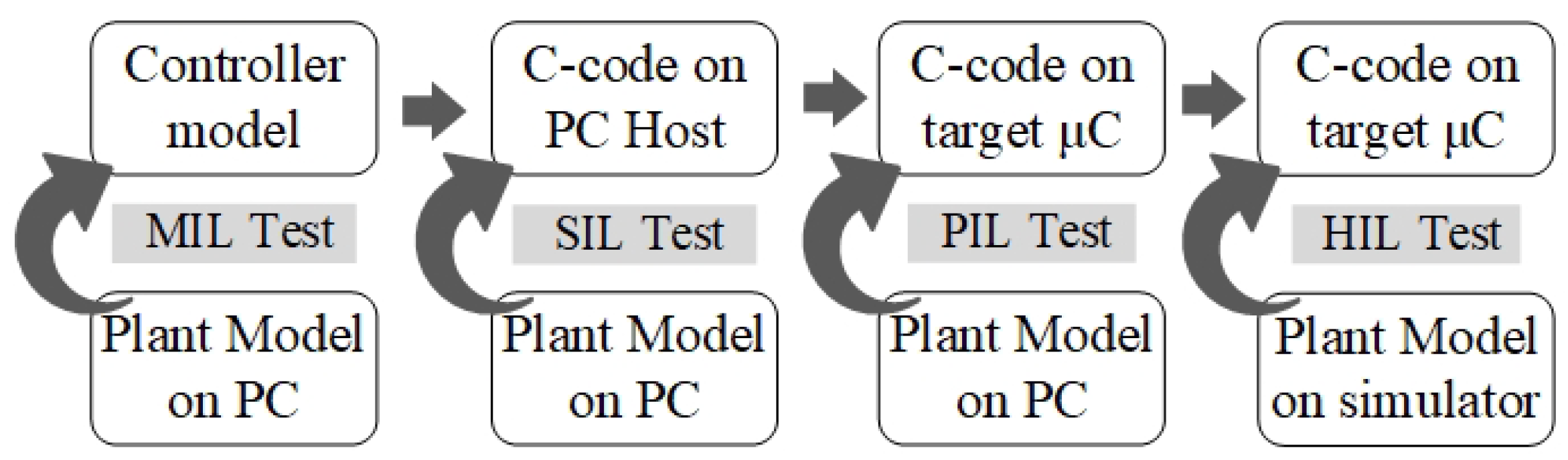
2.1. Model-Based Design Approach for MPPT Controllers

MBD accelerates the development of embedded systems by enabling progressive validation at multiple stages of the software lifecycle [32]. The approach follows a structured workflow, where control logic is first tested in a simulated environment before being deployed on the hardware. By incorporating MBD into the MPPT development process, design flaws can be detected and corrected early, reducing debugging time and minimizing costly modifications in later stages [32].
One of MBD’s key advantages is its flexibility in handling design modifications while maintaining overall system consistency [33]. By validating software components through simulation and iterative refinement, MBD significantly reduces the risk of integration failures, ensuring that the final implementation meets operational requirements. For MPPT controllers, this methodology enhances code reliability, computational efficiency, and adaptability to dynamic environmental conditions.
The verification and validation (V&V) process in MBD consists of three key testing levels [34], each serving a distinct purpose in ensuring software correctness and performance (see Figure 1):
  • Model-in-the-Loop (MIL) Testing: The initial validation stage, where the MPPT control algorithm is tested in a simulated environment to ensure that it meets system requirements. MIL testing verifies that the control model behaves as expected under different operating conditions before proceeding to code generation [32].
  • Software-in-the-Loop (SIL) Testing: After MIL, the control algorithm is automatically converted into C code and tested within a software simulation environment to verify that the compiled code produces the same results as the original model, ensuring functional consistency [32].
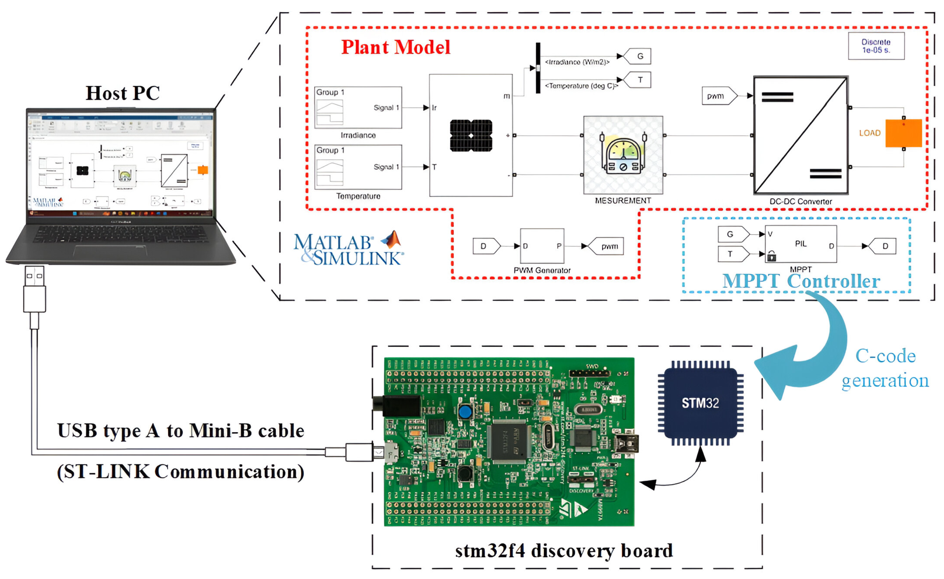
  • Processor-in-the-Loop (PIL) Testing: This stage bridges simulation and real hardware implementation. The MPPT algorithm is executed on the target microcontroller (STM32F4) while interfacing with a simulated PV system. PIL testing allows developers to evaluate real-time computational performance, software-hardware interactions, and potential integration challenges before full deployment [33].
PIL testing offers several key advantages over conventional validation methods [33]. It provides greater realism by incorporating microcontroller-specific constraints such as processing power limitations and memory restrictions, which may not be captured in purely software-based simulations. Additionally, it enables early hardware interaction testing, allowing potential system incompatibilities to be identified before full hardware deployment. Finally, PIL testing allows the software to interact with simulated hardware features, ensuring that the controller functions as expected in the final embedded environment [34].

2.2. V-Model Development Process for MPPT Validation

Traditional software development methodologies often face inconsistencies, leading to integration issues and costly debugging. The V-Model development framework has become a widely adopted approach for embedded system validation, particularly in safety-critical applications such as automotive and aerospace industries [34]. It integrates a top-down approach, where system specifications and mathematical models are defined upfront, with a bottom-up validation process, where each development phase undergoes rigorous testing [35].
In this context, ISO 26262 [35], an international standard for the functional safety of embedded systems, emphasizes the importance of a structured V&V process to ensure software reliability. Specifically, ISO 26262-6 recommends using MBD and automatic code generation, along with progressive testing stages to validate the performance and compliance of algorithms before deployment on embedded hardware. Applying this standard reduces development errors and ensures that the implemented software aligns with its initial specifications.
As illustrated in Figure 2, the V-Model follows this approach by establishing a direct correlation between the design phases (mathematical modeling and control algorithm development) and the validation stages, including MIL, SIL, and PIL.
In this study, we apply this methodology to validate two advanced MPPT control strategies: ANFIS-FTSC and ANFIS-BS. By integrating the three successive MBD testing levels, we ensure the consistency and robustness of the algorithms.
By adopting this structured approach, we ensure that the transition from Simulink modeling to embedded implementation is reliable and meets system requirements. This guarantees precise MPP tracking, efficient execution on the microcontroller, and robust software performance for real-time photovoltaic applications.

3. Photovoltaic System Modeling

Optimizing the performance of PV systems relies on an accurate mathematical model that describes their electrical characteristics. A PV system consists of a solar generator, a DC-DC converter, and an MPPT controller, which dynamically adjusts the load to extract maximum power from the solar panel. Figure 3 and Figure 4 illustrate the overall system architecture. In Figure 3, the PV generator supplies power to the load through a Boost converter controlled by the proposed ANFIS-FTSC MPPT controller, while in Figure 4, the PV generator is connected to the load via a SEPIC converter regulated by the ANFIS-BS MPPT controller.

3.1. PV Module

A PV module consists of solar cells, which operate based on the PN junction diode principle, converting sunlight into electrical energy. Various models exist to represent PV cell behavior, including Rs-Rp (series-parallel resistance models), double-diode models, and single-diode models [36]. To balance accuracy and computational efficiency, the single-diode model is widely used, as shown in Figure 3 and Figure 4.
In this model, the series resistance R s significantly affects the output voltage and current, while the shunt resistance R s h has a negligible impact and is often omitted in simplified formulations. The current generated by the PV cell can be expressed as follows:
I p v = I p h I d exp ( ϕ ) 1 V p v + R s I p v R s h
where:
ϕ = V p v + R s I p v n s V t
The thermal voltage of the cell is given by:
V t = a k b e T
The photocurrent depends on the irradiance and temperature as:
I p h = I s c + k i ( T 270 ) G 1000
The diode reverse saturation current is defined as:
I d = I d r T 298 3 exp q E g n s k b V t 1 298 1 T
where:
  • I p h : Photogenerated current, which depends on irradiance and temperature.
  • I d : Diode current, responsible for the nonlinear characteristics of the PV cell.
  • I s c : Short-circuit current of the PV module.
  • R s : Series resistance, which affects voltage and current.
  • R s h : Shunt resistance, often neglected for simplicity.
  • n s : Number of series-connected cells in the PV module.
  • V t : Thermal voltage, dependent on the cell temperature.
  • k b : Boltzmann’s constant.
  • e: Electron charge.
  • E g : Energy bandgap of the semiconductor material.
These equations describe the current-voltage characteristics of the PV module and how they evolve under different environmental conditions.

3.2. DC-DC Converter

DC-DC converters play a crucial role in adjusting voltage and current levels to extract maximum power from PV modules efficiently. These power electronic devices act as an interface between the PV generator and the load, ensuring that the system operates at its Maximum Power Point (MPP) under varying irradiance and temperature conditions. In this study, two nonlinear DC-DC converters are employed: a Boost converter, which steps up the PV voltage to a higher level, and a Single-Ended Primary Inductor Converter, which allows output voltage regulation above, below, or equal to the input voltage. Both converters are controlled using intelligent MPPT strategies (ANFIS-FTSC and ANFIS-BS) to optimize energy extraction from the PV system.

3.2.1. Boost Converter

The Boost converter is a widely used power conversion topology designed to increase the input DC voltage while maintaining power balance. It consists of an inductor (L), a switch (S), a diode (D), and an output capacitor (C), as illustrated in Figure 3. The inductor stores energy during the switch-on state and releases it to the load during the switch-off state, thereby increasing the output voltage.
In the context of MPPT, the duty cycle D plays a crucial role in regulating the converter’s behavior. The optimal duty cycle at MPP is expressed as:
D m p p = 1 V m p p P m p p × R l o a d
where:
  • P m p p : Maximum power output of the PV panel.
  • R l o a d : Equivalent resistance of the converter.
  • V m p p : PV panel voltage at MPP.
  • D m p p : Desired duty cycle to maintain MPPT.
Applying the averaging method to derive the state-space model, the dynamic equations of the Boost converter are given as follows:
d V p v d t = 1 C i n ( i p v i L )
d i L d t = 1 L V p v 1 L V 0 ( 1 u ) + Δ ( t )
d V o d t = 1 R C 0 V 0 + 1 C 0 i L ( 1 u )
where:
  • i L : Inductor current.
  • u [ 0 , 1 ] : PWM duty cycle.
  • V 0 : Output voltage.
  • R: Load resistance.
  • Δ ( t ) : System uncertainties, satisfying:
| Δ ( t ) | μ ; μ > 0
These equations describe the voltage and current dynamics of the Boost converter, essential for designing control strategies for MPPT.

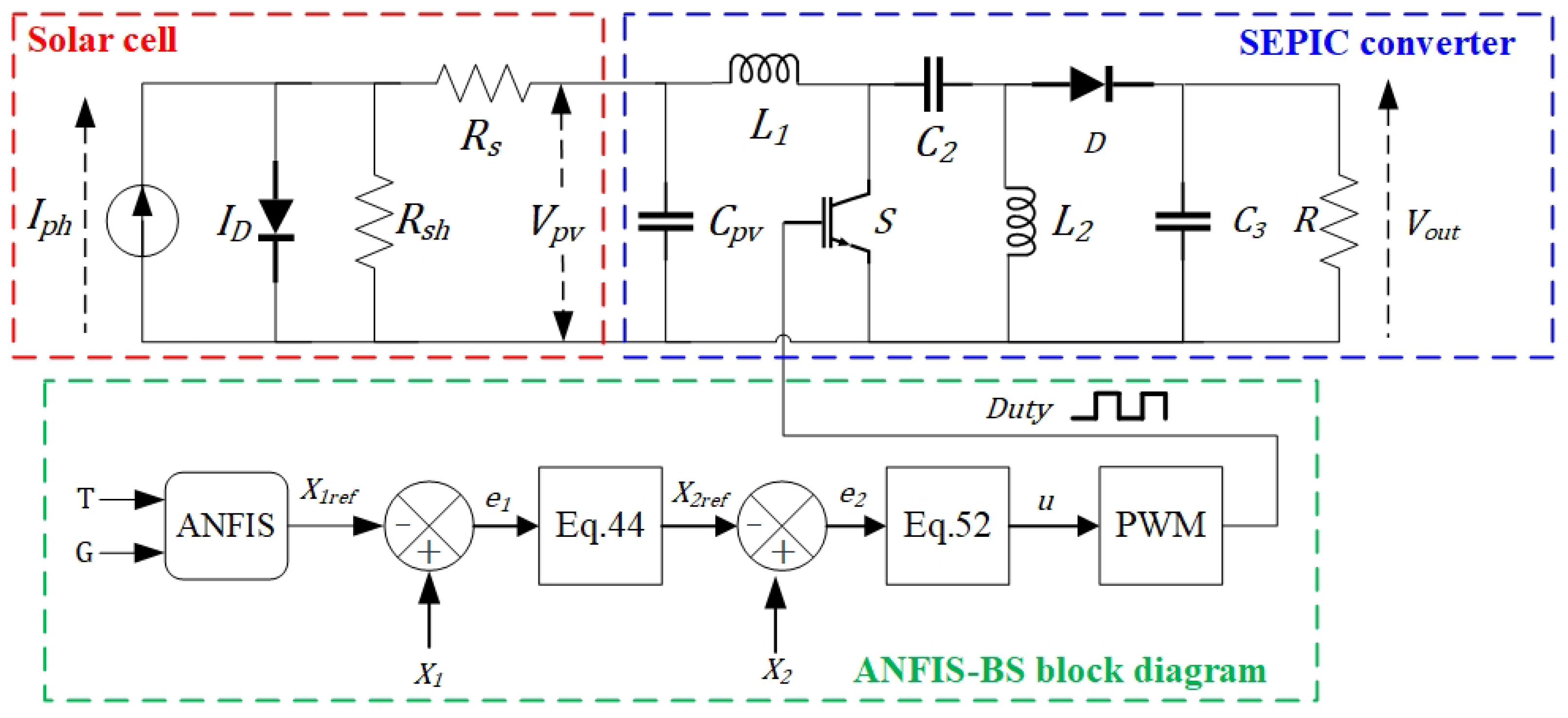
3.2.2. SEPIC Converter

The SEPIC Converter is a versatile DC-DC topology capable of producing an output voltage that is higher, lower, or equal to the input voltage. It combines a BOOST converter and an inverted Buck-Boost converter, allowing smooth voltage regulation while reducing input current ripple [37].
The SEPIC topology consists of two inductors L 1 and L 2 for energy storage, two capacitors C 2 and C 3 for voltage filtering, a switch S, and a diode D for power regulation, as illustrated in Figure 4.
To analyze its operation, a state-space model is used to describe the system in two modes: switch ON and switch OFF [38]. The dynamic equations governing the SEPIC converter are given as:
d I L 1 d t = ( u 1 ) V C 2 L 1 + ( u 1 ) V o u t L 1 + V P V L 1
d V C 2 d t = ( 1 u ) I L 1 C 2 + d I L 2 C 2
d I L 2 d t = d V C 2 L 2 + ( 1 u ) V o u t L 2
d V o u t d t = ( 1 u ) I L 1 C 3 + ( u 1 ) I L 2 C 3 V o u t R C 3
where:
  • I L 1 , I L 2 : Inductor currents.
  • V C 2 : Capacitor voltage.
  • V o u t : Output voltage.
  • u: PWM duty cycle.
This mathematical model is crucial for controller design, as it allows for precise tuning of the MPPT strategy applied to the SEPIC converter.

4. Proposed Control Methodology for Optimal Power Extraction

In PV systems, MPPT is a crucial control strategy designed to maximize energy extraction under varying environmental conditions. Due to the non-linear characteristics of PV modules, the MPP fluctuates with changes in irradiance and temperature, requiring a real-time control mechanism to optimize power generation.
This study employs a dual-loop MPPT control architecture, as shown in Figure 5. The outer loop utilizes an ANFIS to dynamically generate the optimal reference voltage ( V pv - ref ), ensuring continuous tracking of the MPP. The inner loop is responsible for regulating the actual PV voltage ( V pv ) to match V pv - ref , thereby optimizing energy transfer to the load. Two nonlinear control strategies are implemented in this study:
  • Fast Terminal Synergetic Control, which ensures rapid convergence to the MPP with improved robustness.
  • Nonlinear Backstepping Control, which guarantees adaptive regulation and enhances system stability.

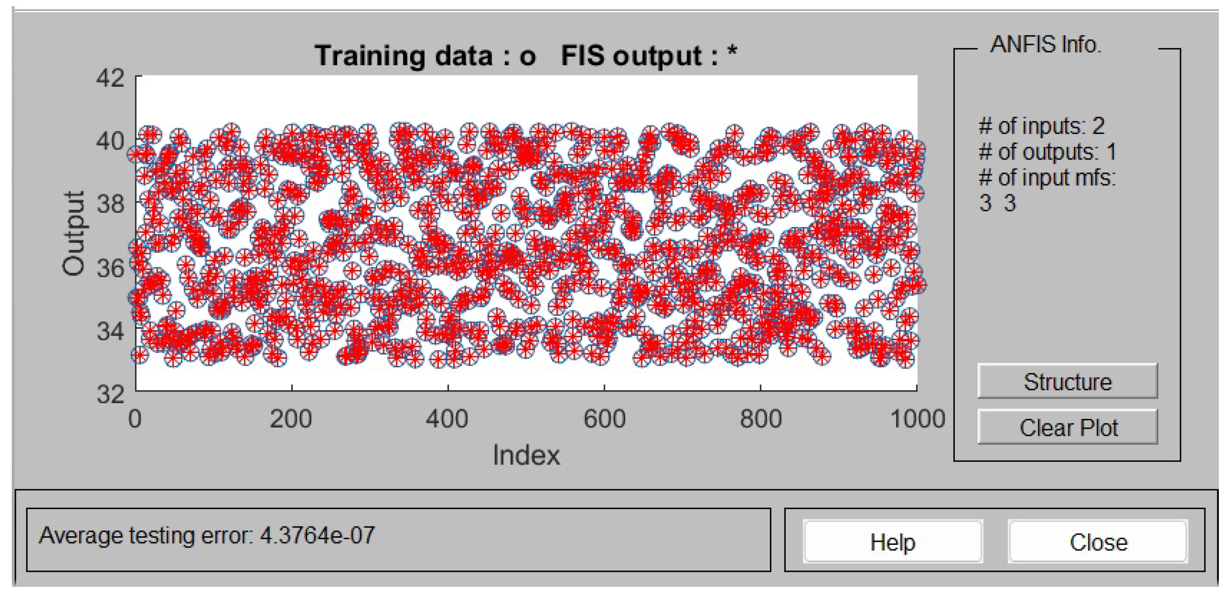
4.1. Reference Voltage Generation Using ANFIS

The ANFIS combines the advantages of ANNs and fuzzy inference systems, particularly the Takagi-Sugeno (TS) model, to enhance the dynamic performance and robustness of MPPT [39]. The ANFIS structure employed in this work consists of five interconnected layers: Fuzzification, Rule Evaluation, Normalization, Consequent Evaluation, and Aggregation, as depicted in Figure 6. Adaptive nodes are represented by squares, whereas non-adaptive nodes are circular [40].
The first step in the ANFIS approach involves fuzzifying crisp input values—solar irradiance (G) and temperature (T)—into fuzzy membership grades. For this task, Gaussian membership functions are selected due to their smooth transition property, essential for accurate MPPT under rapidly changing environmental conditions [41]. These functions are mathematically defined as:
O 1 , i = μ A i ( x ) = exp ( x c i ) 2 2 a i 2 , i = 1 , 2 , 3
where a i and c i are adjustable parameters, and x is the input variable (irradiance or temperature). In our implementation, each input parameter is represented by three Gaussian membership functions, resulting in a total of nine fuzzy inference rules (3 irradiance sets × 3 temperature sets). These rules generate the V pv - ref for maximum power extraction via linear functions.
The ANFIS inference employs TS fuzzy rules, structured in the conventional “If-Then” format, illustrated in Figure 7.
For instance, a simplified system with two fuzzy rules is defined as:
Rule 1: If x is A 1 and y is B 1 , then f 1 = p 1 x + q 1 y + r 1 .
Rule 2: If x is A 2 and y is B 2 , then f 2 = p 2 x + q 2 y + r 2 .
Here, x and y denote the input variables (G and T), A i and B i represent fuzzy sets with Gaussian membership functions, and the coefficients p i , q i , and r i are parameters optimized during ANFIS training.
The second layer performs rule evaluation using the product operation (AND), defined as:
O 2 , i = w i = μ A i ( x ) μ B i ( y ) , i = 1 , 2 , , 9
In the third layer, normalization of firing strengths occurs, ensuring proportional contributions of rules:
O 3 , i = w ¯ i = w i j = 1 9 w j , i = 1 , 2 , , 9
The fourth layer calculates the consequent outcomes of fuzzy rules:
O 4 , i = w ¯ i f i = w ¯ i ( p i x + q i y + r i ) , i = 1 , 2 , , 9
Finally, the fifth layer aggregates all the rule outcomes to produce the ANFIS output:
O 5 = f = i = 1 9 O 4 , i = i = 1 9 w i f i i = 1 9 w i
The training dataset for the ANFIS model comprises both historical measurements and synthetic data. Historical data were collected over a 12-month period from a real photovoltaic installation, ensuring a diverse representation of operational conditions. Synthetic data were generated using MATLAB R2021a, developed by MathWorks, with a valid academic license to capture extreme scenarios rarely encountered in real-world datasets, thereby enhancing the generalization capabilities and robustness of the ANFIS controller. To evaluate the training performance, we used the ANFIS editor in MATLAB to monitor the prediction accuracy of the model. As shown in Figure 8, the red stars (*) represent the ANFIS output while the blue circles denote the original training data. The close overlap between both sets confirms excellent learning accuracy. The average testing error reached a remarkably low value of 4.3764 × 10 7 . This indicates that the generated model can effectively map the input irradiance and temperature to the optimal reference voltage with minimal prediction error.

4.2. Fast Terminal Synergetic Control

FTSC is an advanced nonlinear control technique that ensures finite-time convergence to MPP. It is based on Synergetic Control Theory, which defines a macro-variable trajectory that guides the system towards stability [42,43]. The flow chart illustrating the control logic and signal flow of the FTSC algorithm is presented in Figure 3.
The FTSC control law is derived from the system’s nonlinear dynamics, given by:
d X d t = f ( X , d , t )
where X represents the system state vector, d is the control input (duty cycle), and f ( X , d , t ) describes the system behavior. The synergetic control method imposes the following constraint on the macro-variable:
T s d Ψ d t + Ψ = 0 , T s > 0
where T s is the time constant influencing the convergence speed. Differentiating Ψ and substituting the system dynamics, we derive the FTSC control law:
T s d Ψ d X f ( X , d , t ) + Ψ = 0
which can be rearranged to solve for the control input:
d = g ( X , t , Ψ ( X , t ) , T s )
To formulate the FTSC control strategy, we begin by defining the tracking objective of the system: the PV voltage and the inductor current must converge to their respective reference values. The state variables are denoted as x 1 = V p v and x 2 = i L , with the voltage reference defined as:
x 1 r e f = V p v r e f
The first tracking error is expressed as:
e 1 = x 1 x 1 r e f
This error is used to compute the current reference from the dynamic model of the system:
x 2 r e f = I p v C i n x ˙ 1 r e f
The second error is then computed as:
e 2 = x 2 x 2 r e f
The error dynamics are then expressed as:
e ˙ 1 = e 2 C i n , e ˙ 2 = V p v L ( 1 d ) L ( V o u t + V C 2 ) x ˙ 2 r e f
We define new variables to simplify the control derivation:
Z 1 = e 1 , Z 2 = e 2 C i n
The macro-variable Ψ of the FTSC controller is defined as:
Ψ = Z ˙ 1 + α Z 1 + β Z 1 p / q
with α > 0 , β > 0 , and p < q . This macro-variable drives the error to zero within a finite time, given by:
t s = q α ( q p ) ln α Z 1 ( 0 ) 1 p / q + β β
Differentiating Ψ , we obtain:
Ψ ˙ = Z ˙ 2 + α Z 2 + β p q Z 2 Z 1 ( p / q 1 )
By substituting system dynamics into the synergetic condition, the control law is derived as:
d F T S C = 1 + L V o C i n Ψ T s + α Z 2 + β p q Z 2 Z 1 ( p / q 1 ) V p v L + x ˙ 2 r e f
A Lyapunov stability analysis is performed to ensure the stability of the FTSC-based MPPT controller. The Lyapunov candidate function is chosen as:
V = 1 2 Ψ 2
Differentiating V with respect to time:
V ˙ = Ψ Ψ ˙
From the system dynamics:
Ψ ˙ = Z ¨ 1 + α Z ˙ 1 + β p q Z ˙ 1 Z 1 ( p / q 1 )
Substituting the FTSC control law:
Ψ ˙ = 1 T s ( Z ˙ 1 + α Z 1 + β Z 1 ( p / q ) )
Thus, the time derivative of the Lyapunov function simplifies to:
V ˙ = Z ˙ 1 + α Z 1 + β Z 1 ( p / q ) 1 T s ( Z ˙ 1 + α Z 1 + β Z 1 ( p / q ) )
V ˙ = 1 T s ( Z ˙ 1 + α Z 1 + β Z 1 ( p / q ) ) 2 0
Since V ˙ 0 , the system is globally stable, ensuring that the tracking error converges to the attractor Ψ = 0 within a finite time t s . This confirms the robustness of the FTSC-based MPPT control strategy under dynamic environmental conditions.

4.3. Backstepping Control

The nonlinear BS control method provides a systematic and robust framework for MPPT in photovoltaic systems. It ensures that the PV voltage converges to its reference by dynamically adjusting the duty cycle of the SEPIC converter. Figure 4 illustrates the control architecture, where the error e 1 is first used to generate the current reference, followed by the calculation of the second error e 2 , which is used to derive the control law.
We define the system states as x 1 = V p v and x 2 = I L 1 , with a voltage reference given by:
x 1 r e f = V p v r e f
The first tracking error is defined as:
e 1 = x 1 x 1 r e f
To enforce voltage tracking, we impose the stabilization condition:
e ˙ 1 = K 1 e 1
From the system dynamics, we have:
x ˙ 1 = 1 C p v ( I p v x 2 )
Substituting into the stabilization condition gives:
1 C p v ( I p v x 2 ) = K 1 e 1 + x ˙ 1 r e f
Solving for the desired inductor current x 2 r e f , we obtain:
x 2 r e f = I p v + C p v ( K 1 e 1 x ˙ 1 r e f )
The second tracking error is then defined as:
e 2 = x 2 x 2 r e f
To prove stability, we construct a Lyapunov function candidate:
V = 1 2 e 1 2 + 1 2 e 2 2
Differentiating V, we get:
V ˙ = e 1 e ˙ 1 + e 2 e ˙ 2
Using the relation e ˙ 1 = K 1 e 1 , and the system dynamics for the inductor current:
x ˙ 2 = V p v L ( 1 u ) L ( V o u t + V C 2 )
then,
e ˙ 2 = x ˙ 2 x ˙ 2 r e f
Substituting all into V ˙ :
V ˙ = K 1 e 1 2 + e 2 V p v L ( 1 u ) L ( V o u t + V C 2 ) x ˙ 2 r e f
To ensure stability, we impose:
V p v L ( 1 u ) L ( V o u t + V C 2 ) x ˙ 2 r e f = K 2 e 2
Solving for the duty cycle u, the final control law becomes:
u = 1 V p v + L ( K 2 e 2 x ˙ 2 r e f ) V C 2 + V 0
Substituting this into the Lyapunov derivative gives:
V ˙ = K 1 e 1 2 K 2 e 2 2 0
This confirms the global asymptotic stability of the system. Thus, the proposed Backstepping controller ensures accurate MPPT tracking and stable operation under dynamic conditions.

5. Results

The implementation of an MPPT algorithm for a PV system requires rigorous testing to ensure optimal performance and compliance with the design specifications. Given the complexity of embedded control systems, validation is essential at multiple levels before deploying the algorithm onto the actual hardware. This section outlines the results of a structured test-driven approach, incorporating SIL and PIL testing. These methodologies facilitate the transition from simulation to real-world execution by progressively verifying the correctness, efficiency, and robustness of the developed control algorithms. The key parameters of the PV panel used in this study are detailed in Table 1.

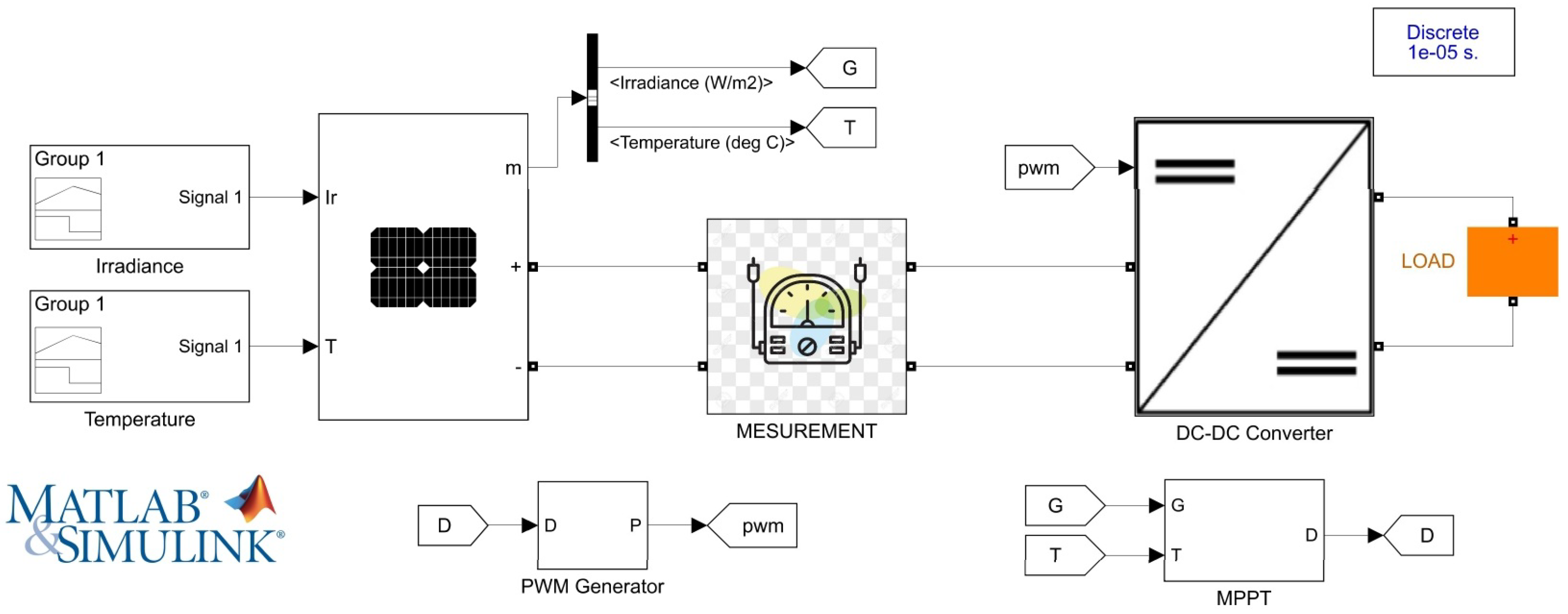
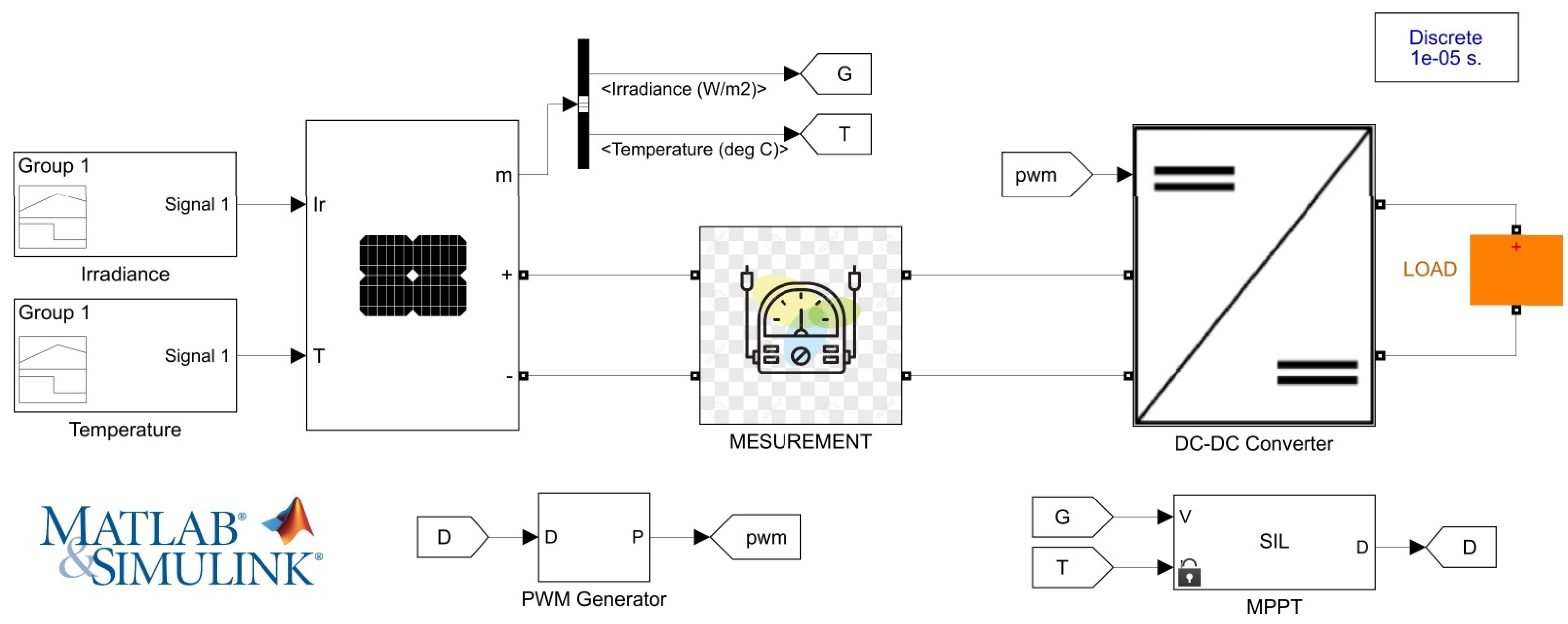
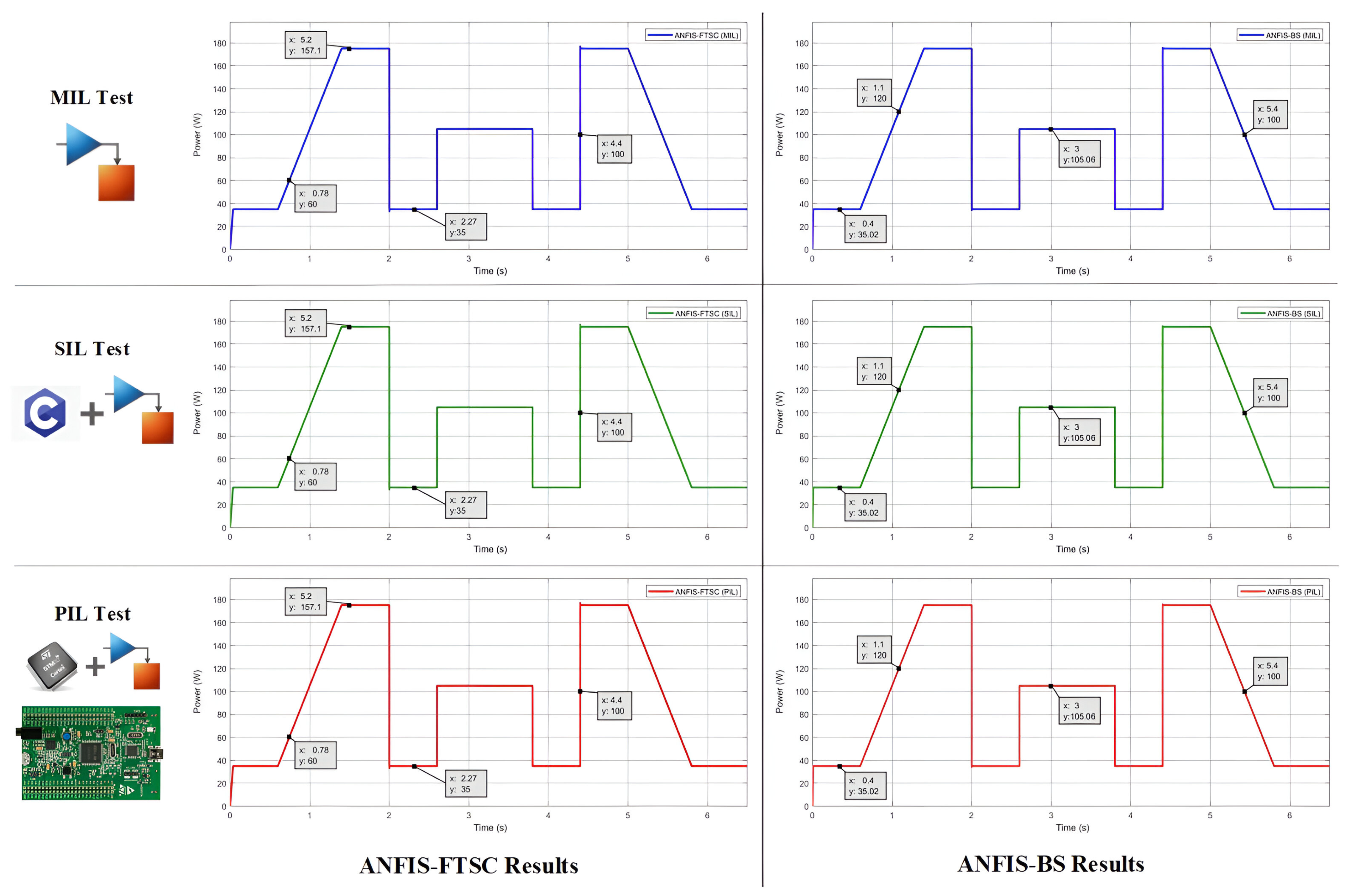
5.1. Model-in-the-Loop Testing

The MIL validation serves as the first step in the verification process of the ANFIS-FTSC and ANFIS-BS MPPT controllers. This phase ensures that the control algorithms perform as expected when applied to the complete PV system model, before transitioning to embedded execution [44]. The entire MPPT control loop, DC-DC converter, and PV model are simulated in Simulink to verify stability, efficiency, and real-time tracking capabilities [45]. The Simulink model used for MIL validation is illustrated in Figure 9. All simulations were carried out using MATLAB/Simulink R2021a with a valid academic license.
To evaluate the controllers’ response under realistic operating conditions, the Ramp-Up and Step-Change Profile (ROPP Test) [46] was applied, as used in previous MPPT validation studies. The irradiance profile consists of a gradual increase from 200 W/m2 to 1000 W/m2, followed by four abrupt step changes (1000 → 200, 200 → 600, 600 → 200, 200 → 1000 W/m2). Finally, a progressive decrease from 1000 W/m2 back to 200 W/m2 is applied to assess the controller’s ability to track the MPP under fluctuating conditions.
Figure 12, presents the MIL test results for both controllers, illustrating the real-time power tracking response under dynamic irradiance conditions. These simulations confirm that both ANFIS-based MPPT strategies effectively track the MPP with high efficiency and minimal oscillations. The detailed performance evaluation in terms of convergence speed, steady-state oscillations, and tracking accuracy was already validated in [25,26], demonstrating their superiority over conventional MPPT techniques.
Since the objective of this study is not to revalidate the control strategies but rather to verify their embedded implementation, the next step consists of SIL testing. This phase evaluates whether the automatically generated C code maintains the same performance observed in MIL simulations when executed in a real-time software environment.

5.2. Software-in-the-Loop Testing

SIL testing serves as an intermediate step between pure simulation (MIL) and real hardware execution (PIL), ensuring that the automatically generated C code accurately replicates the behavior of the original Simulink model [44]. This phase is critical to validate the consistency, numerical accuracy, and execution performance of the MPPT control algorithms before deploying them on embedded hardware.
In this test, the ANFIS-FTSC and ANFIS-BS controllers, initially implemented as high-level Simulink models, are automatically converted into C code using MATLAB Embedded Coder. The generated C code is then integrated into an S-Function block and executed within the same Simulink environment used in the MIL phase (Figure 10). This setup enables a direct comparison between the MIL and SIL results, ensuring that the transition from model-based simulation to embedded execution does not introduce numerical discrepancies or performance degradation.
The ROPP test was applied to assess the fidelity of the SIL implementation, following the same irradiance profile used in the MIL validation. Figure 12 presents the results of the SIL test, demonstrating that both controllers maintain the same MPP tracking performance as observed in the MIL phase. The power response, tracking accuracy, and transient behavior exhibit a high degree of similarity, confirming that the C code implementation accurately preserves the designed control logic.
Since the SIL results are fully aligned with the MIL results, the next logical step is the PIL testing, where the C code is executed directly on the STM32F4 microcontroller.

5.3. Processor-in-the-Loop Testing

The PIL test represents the final validation stage in the development of the MPPT algorithm. This step ensures that the compiled control algorithm runs correctly on the target microcontroller, maintaining its expected performance while accounting for real-time computational constraints.
To perform the PIL test, the MPPT controller subsystem is converted to optimized C code using MATLAB/Simulink embedded coder. The generated code is then uploaded to the STM32F4 microcontroller and executed in real time. The STM32F4 Discovery board was selected for this validation due to its ARM Cortex-M4F processor (168 MHz), floating point unit, 1 MB flash memory, and 192 KB SRAM, making it well suited for high-speed numerical computations in real-time DSP applications.
The PIL test block diagram, used in this study, is shown in Figure 11. The deployment process involves flashing the code compiled onto the microcontroller using OpenOCD, which enables efficient host-to-target communication. The ST-Link interface is used to establish a USB-based connection between the STM32F4 board and the MATLAB/Simulink environment [47], facilitating real time data exchange for performance monitoring.
Figure 12 presents the PIL test results, confirming that the MPPT response closely matches the MIL and SIL results. The observed tracking accuracy, power stability, and convergence speed indicate that the embedded execution preserves the control performance initially verified in simulation-based validation. The negligible numerical difference between SIL and PIL outputs demonstrates that the MPPT controllers are fully compatible with real-time embedded implementation.
With PIL validation complete, the MPPT algorithms are now ready for real-world deployment, ensuring high-efficiency energy harvesting in practical PV systems.

6. Discussion

The validation process ends with an analysis and comparison of the MIL, SIL, and PIL results. This ensures that the MPPT algorithms maintain their expected performance across different execution environments. To evaluate the ANFIS-FTSC and ANFIS-BS controllers, the ROPP test was applied in all validation stages, verifying their ability to maintain fast and stable convergence to the MPP under rapid irradiance variations, assess consistency between different testing phases, and analyze computational efficiency in real-time execution.
The tracking responses in Figure 12 demonstrate that both controllers effectively track the MPP with minimal oscillations and rapid convergence. The SIL and PIL results closely match the MIL output, confirming that automated code generation preserves the expected performance in embedded execution. As recommended by ISO 26262-6, ensuring that the PIL results align with the MIL and SIL outputs is essential to guarantee software reliability. Discrepancies between these tests may indicate potential issues in model accuracy, software generation, or hardware execution.
If the MIL results deviate from the expected MPPT behavior, the Simulink model requires refinement. If SIL results differ from MIL, the generated C code may contain errors, necessitating software verification. If PIL results diverge from SIL and MIL, it suggests execution inconsistencies on the STM32F4 Discovery board, which requires debugging and performance analysis. In this study, the PIL results align closely with MIL and SIL, confirming the accuracy and reliability of the embedded implementation.
The ANFIS-FTSC and ANFIS-BS controllers were compared with existing MPPT strategies in terms of tracking efficiency, response time, and power stability. Table 2 includes a selection of recent MPPT techniques that were implemented on embedded platforms, among which some, such as the recent work of Manna et al. (2024) [48] using a dSPACE 1202 controller (dSPACE GmbH, Paderborn, Germany), were tested under the same ROPP irradiance profile. This partial overlap strengthens the benchmarking consistency and supports a fair assessment of the proposed controllers’ real-time performance.
The results show that both proposed controllers outperform conventional and recent MPPT implementations in terms of accuracy and convergence speed. Specifically, the ANFIS-FTSC achieves a tracking efficiency of 99.89% with a response time of 37 ms, while the ANFIS-BS reaches 99.6% in just 9 ms, demonstrating superior dynamic response and power stability.
The tracking efficiency is calculated using the following expression:
Tracking efficiency = Actual tracked power Maximum power available at a given condition
These high-efficiency values were obtained under the standard ROPP test profile, a well-known benchmark for dynamic MPPT performance evaluation.
Overall, the comparison confirms that the proposed MPPT strategies are not only effective in simulation but also well-suited for real-time embedded applications, delivering efficient and stable energy harvesting under rapidly changing environmental conditions.
While the proposed ANFIS-FTSC and ANFIS-BS controllers exhibit high tracking accuracy and efficient real-time performance, their computational complexity remains higher than conventional methods, which may impact execution time on resource-limited processors. Additionally, this study focused on simulation and MBD validation; real-world implementation may introduce additional challenges, such as sensor inaccuracies and power losses.
Future work will focus on optimizing computational efficiency, conducting real-time hardware validation, and exploring IoT-based remote monitoring for intelligent energy management in large-scale PV systems.

7. Conclusions

This study presents a structured AI-driven nonlinear MPPT control approach, featuring the innovative ANFIS-FTSC and ANFIS-BS controllers. By integrating Artificial Intelligence (AI) with advanced nonlinear control strategies, these controllers demonstrate exceptional efficiency, stability, and adaptability for photovoltaic systems. Rigorous validation through MIL, SIL, and PIL testing confirms their robustness and suitability for real-time embedded applications. The results highlight the reliability of the embedded implementation, with PIL outputs aligning closely with MIL and SIL results, adhering to ISO 26262-6 functional safety guidelines. The controllers achieve over 99.5% tracking efficiency, rapid convergence, and minimal oscillations, outperforming conventional MPPT methods.
From a practical perspective, the proposed MPPT strategies demonstrate a strong potential for real-world deployment in embedded PV systems such as smart microgrids, standalone solar units, and mobile energy platforms. However, some challenges remain for large-scale engineering integration. These include the computational cost of ANFIS inference on low-power microcontrollers, the potential need for high-resolution sensors, and the trade-off between model complexity and execution speed. Moreover, a key direction will involve retraining the ANFIS models using only electrical measurements, such as voltage and current, instead of relying on irradiance and temperature sensors. This transition aims to simplify hardware deployment, reduce sensor costs, and facilitate broader applicability in embedded PV platforms. Building on this practical foundation, future research will now focus on hardware-in-the-loop (HIL) validation and real-world deployment on physical PV systems to further evaluate performance under practical conditions.
Additionally, optimizing computational efficiency and integrating advanced machine learning techniques could enhance adaptability to extreme environmental variations, paving the way for more resilient and intelligent energy harvesting systems. By combining structured verification and embedded validation, this study advances the development of reliable, high-performance MPPT controllers, ensuring optimal energy harvesting for real-time photovoltaic applications. These contributions not only improve the efficiency of PV systems but also support the broader adoption of renewable energy technologies in a sustainable energy future.

Author Contributions

Conceptualization, K.C. and H.J.; methodology, K.C.; validation, K.C. and M.A.T.; writing—original draft preparation, K.C.; writing—review and editing, M.A.T., M.A.I. and E.T.; supervision, H.J. and M.A.T.; Funding acquisition, M.A.I. and E.T.; project administration, H.A. All authors have read and agreed to the published version of the manuscript.

Funding

This research received no external funding.

Data Availability Statement

Data sharing is available if requested.

Acknowledgments

The authors extend their appreciation to the Northern Border University, Saudi Arabia, for supporting this work through project number “NBU-CRP-2025-2448”.

Conflicts of Interest

The authors declare no conflicts of interest.

Abbreviations

The following abbreviations are used in this manuscript:
PVPhotovoltaic
MPPTMaximum Power Point Tracking
ANFISAdaptive Neuro-Fuzzy Inference System
FTSCFast Terminal Synergetic Control
BSBackstepping
SEPICSingle-Ended Primary Inductor Converter
PILProcessor-in-the-Loop
MBDModel-Based Design
DC-DCDirect Current to Direct Current
P&OPerturb and Observe
INCIncremental Conductance
FLCFuzzy Logic Control
ANNsArtificial Neural Networks
PSOParticle Swarm Optimization
GAGenetic Algorithms
ACOAnt Colony Optimization
MILModel-in-the-Loop
SILSoftware-in-the-Loop
ANFIS-FTSCAdaptive Neuro-Fuzzy Inference System with Fast Terminal Synergetic Control
ANFIS-BSAdaptive Neuro-Fuzzy Inference System with Backstepping
MPPMaximum Power Point
V&VVerification and Validation
V p v r e f Optimal Reference Voltage
V p v Actual PV Voltage
GIrradiance
TTemperature

References

  1. Zoungrana, R.; Çakmakci, M. From non-renewable energy to renewable by harvesting salinity gradient power by reverse electrodialysis: A review. Int. J. Energy Res. 2021, 45, 3495–3522. [Google Scholar] [CrossRef]
  2. Solarin, S.A.; Al-Mulali, U.; Ozturk, I. Validating the environmental Kuznets curve hypothesis in India and China: The role of hydroelectricity consumption. Renew. Sustain. Energy Rev. 2017, 80, 1578–1587. [Google Scholar] [CrossRef]
  3. Mekhilef, S.; Saidur, R.; Safari, A.; Mustaffa, W. Biomass energy in Malaysia: Current state and prospects. Renew. Sustain. Energy Rev. 2011, 15, 3360–3370. [Google Scholar] [CrossRef]
  4. Bollipo, R.B.; Mikkili, S.; Bonthagorla, P.K. Critical review on PV MPPT techniques: Classical, intelligent and optimisation. IET Renew. Power Gener. 2020, 14, 1433–1452. [Google Scholar] [CrossRef]
  5. Liu, Z.; Cheng, X.; Peng, X.; Wang, P.; Zhao, X.; Liu, J.; Jiang, D.; Qu, R. A review of common-mode voltage suppression methods in wind power generation. Renew. Sustain. Energy Rev. 2024, 203, 114773. [Google Scholar] [CrossRef]
  6. Killi, M.; Samanta, S. Modified perturb and observe MPPT algorithm for drift avoidance in photovoltaic systems. IEEE Trans. Ind. Electron. 2015, 62, 5549–5559. [Google Scholar] [CrossRef]
  7. Nkambule, M.S.; Hasan, A.N.; Ali, A.; Hong, J.; Geem, Z.W. Comprehensive evaluation of machine learning MPPT algorithms for a PV system under different weather conditions. J. Electr. Eng. Technol. 2021, 16, 411–427. [Google Scholar] [CrossRef]
  8. Yang, B.; Zhu, T.; Wang, J.; Shu, H.; Yu, T.; Zhang, X.; Yao, W.; Sun, L. Comprehensive overview of maximum power point tracking algorithms of PV systems under partial shading condition. J. Clean. Prod. 2020, 268, 121983. [Google Scholar] [CrossRef]
  9. Elbaset, A.A.; Ali, H.; Abd-El Sattar, M.; Khaled, M. Implementation of a modified perturb and observe maximum power point tracking algorithm for photovoltaic system using an embedded microcontroller. IET Renew. Power Gener. 2016, 10, 551–560. [Google Scholar] [CrossRef]
  10. Choi, H.; Ciobotaru, M.; Jang, M.; Agelidis, V.G. Performance of medium-voltage DC-bus PV system architecture utilizing high-gain DC-DC converter. IEEE Trans. Sustain. Energy 2015, 6, 464–473. [Google Scholar] [CrossRef]
  11. Houssein, E.H.; Mahdy, M.A.; Fathy, A.; Rezk, H. A modified Marine Predator Algorithm based on opposition based learning for tracking the global MPP of shaded PV system. Expert Syst. Appl. 2021, 183, 115253. [Google Scholar] [CrossRef]
  12. Liu, F.; Duan, S.; Liu, F.; Liu, B.; Kang, Y. A variable step size INC MPPT method for PV systems. IEEE Trans. Ind. Electron. 2008, 55, 2622–2628. [Google Scholar]
  13. Raza, M.A.; Zahra, S.; Raza, S.; Altimania, M.R.; Hassan, M.; Munir, H.M.; Zaitsev, I.; Kuchanskyy, V. Mitigating the Impact of Partial Shading Conditions on Photovoltaic Arrays Through Modified Bridge-Linked Configuration. Sustainability 2025, 17, 1263. [Google Scholar] [CrossRef]
  14. Celikel, R.; Yilmaz, M.; Gundogdu, A. A voltage scanning-based MPPT method for PV power systems under complex partial shading conditions. Renew. Energy 2022, 184, 361–373. [Google Scholar] [CrossRef]
  15. Awan; Javed, A.B.M.Y.; Asghar, A.B.; Ejsmont, K. Performance optimization of a ten check MPPT algorithm for an off-grid solar photovoltaic system. Energies 2022, 15, 2104. [Google Scholar] [CrossRef]
  16. Abidi, H.; Sidhom, L.; Chihi, I. Systematic literature review and benchmarking for photovoltaic MPPT techniques. Energies 2023, 16, 3509. [Google Scholar] [CrossRef]
  17. Chnini, K.; Jouini, H.; Allagui, H.; Mami, A. ANFIS-RTSMC based MPPT for a hybrid PV-diesel-battery water pumping system. Meas. Control 2024. [Google Scholar] [CrossRef]
  18. Chnini, K.; Jouini, H.; Allagui, H.; Mami, A. A Novel Nonlinear Intelligent Control Approach for Optimizing Solar PV Systems in Medical Applications Under Dynamic Conditions. In Proceedings of the 2024 IEEE 7th International Conference on Advanced Technologies, Signal and Image Processing (ATSIP), Sousse, Tunisia, 11–13 July 2024; pp. 553–558. [Google Scholar] [CrossRef]
  19. Sarang, S.A.; Raza, M.A.; Panhwar, M.; Khan, M.; Abbas, G.; Touti, E.; Altamimi, A.; Wijaya, A.A. Maximizing solar power generation through conventional and digital MPPT techniques: A comparative analysis. Sci. Rep. 2024, 14, 8944. [Google Scholar] [CrossRef] [PubMed]
  20. Fares, D.; Fathi, M.; Shams, I.; Mekhilef, S. A novel global MPPT technique based on squirrel search algorithm for PV module under partial shading conditions. Energy Convers. Manag. 2021, 230, 113773. [Google Scholar] [CrossRef]
  21. Motahhir, S.; Ghzizal, A.E.; Sebti, S.; Derouich, A. The most used MPPT algorithms: Review and the suitable low-cost embedded board for each algorithm. J. Clean. Prod. 2020, 246, 118983. [Google Scholar] [CrossRef]
  22. Ticona Coaquira, F.J.; Wang, X.; Vidaurre Torrez, K.W.; Mamani Quiroga, M.J.; Silva Plata, M.A.; Luna Verdueta, G.A.; Murillo Quispe, S.E.; Auza Banegas, G.J.; Antezana Lopez, F.P.; Rojas, A. Model-Based Design and Testbed for CubeSat Attitude Determination and Control System with Magnetic Actuation. Appl. Sci. 2024, 14, 6065. [Google Scholar] [CrossRef]
  23. Chtita, S.; Motahhir, S.; El Ghzizal, A. A New Design and Embedded Implementation of a Low-Cost Maximum Power Point Tracking Charge Controller for Stand-Alone Photovoltaic Systems. Energy Technol. 2024, 12, 2301324. [Google Scholar] [CrossRef]
  24. Rimouche, W.; Talha, A.; Boumaaraf, H. Comparative Analysis of Hardware Resource Utilization for MPPT Techniques: P&O, Incremental Conductance, and ANN Using Processor-in-the-Loop Testing on STM32F407. In Proceedings of the 2024 12th International Conference on Systems and Control (ICSC), Batna, Algeria, 3–5 November 2024; pp. 53–59. [Google Scholar] [CrossRef]
  25. Chnini, K.; dhifaoui, D.; Jouini, H.; Allagui, H. Enhancing PV power generation via an adaptive neuro-fuzzy and fast terminal synergetic MPPT approach. Meas. Control 2024, 58, 502–514. [Google Scholar] [CrossRef]
  26. Chnini, K.; Jouini, H.; Allagui, H.; Mami, A. Enhancing power generation via an adaptive neuro-fuzzy and backstepping maximum-power-point tracking approach for photovoltaic single-ended primary inductor converter system. Clean Energy 2024, 8, 34–44. [Google Scholar] [CrossRef]
  27. Cheddadi, B.; Errahimi, F.; Es-sbai, N. Design and verification of photovoltaic MPPT algorithm as an automotive-based embedded software. Sol. Energy 2018, 171, 414–425. [Google Scholar] [CrossRef]
  28. Karmouni, S.; Chouiekh, M.; Motahhir, S.; Qjidaa, H.; Jamil, M.O.; Sayyouri, M. A fast and accurate sine-cosine MPPT algorithm under partial shading with implementation using Arduino board. Clean. Eng. Technol. 2022, 9, 100535. [Google Scholar] [CrossRef]
  29. Boopathi, S.; Sujatha, R.; Senthil Kumar, C.; Narasimman, S. Quantification of software code coverage using artificial bee colony optimization based on Markov approach. Arab. J. Sci. Eng. 2017, 42, 3503–3519. [Google Scholar] [CrossRef]
  30. Coronado-Mendoza, A.; Camas-Náfate, M.; Artal-Sevil, J.S.; Domínguez-Navarro, J.A. Optimum Design of a Photovoltaic Inverter System Based on Ga, Pso and Gwo Algorithms with a Mppt Sliding Mode Control. Energies 2025, 18, 1911. [Google Scholar] [CrossRef]
  31. Strandberg, P.E. Automated System-Level Software Testing of Industrial Networked Embedded Systems. Ph.D. Thesis, Malardalen University, Västerås, Sweden, 2021. [Google Scholar]
  32. De Lemos, R.; Giese, H.; Müller, H.A.; Shaw, M. (Eds.) Software Engineering for Self-Adaptive Systems II. In International Seminar, Dagstuhl Castle, Germany, October 24–29, 2010 Revised Selected and Invited Papers; Lecture Notes in Computer Science; Springer: Berlin/Heidelberg, Germany, 2013; Volume 7475. [Google Scholar]
  33. Megrini, M.; Gaga, A.; Mehdaoui, Y. Processor in the loop implementation of artificial neural network controller for BLDC motor speed control. Results Eng. 2004, 23, 102422. [Google Scholar] [CrossRef]
  34. Hill, A.; de Beeck, J.O.; Baja, M.; Djemili, I.; Reuther, P.; Sutra, I. Use of V-cycle methodology to develop mechatronic fuel system functions. In SAE Technical Paper; SAE International: Warrendale, PA, USA, 2017. [Google Scholar]
  35. Hommes, U. Review and assessment of the ISO 26262 draft road vehicle-functional safety. In SAE Technical Paper; SAE International: Warrendale, PA, USA, 2012. [Google Scholar]
  36. Tao, H.; Ghahremani, M.; Ahmed, F.W.; Jing, W.; Nazir, M.S.; Ohshima, K. A novel MPPT controller in PV systems with hybrid whale optimization-PS algorithm based ANFIS under different conditions. Control. Eng. Pract. 2021, 112, 104809. [Google Scholar] [CrossRef]
  37. Chennoufi, K.; Ferfra, M.; Mokhlis, M. Design and implementation of efficient MPPT controllers based on SDM and DDM using backstepping control and SEPIC converter. In Proceedings of the 2021 9th International Renewable and Sustainable Energy Conference (IRSEC), Benguerir, Morocco, 23–27 November 2021; pp. 1–8. [Google Scholar]
  38. Chennoufi, K.; Ferfra, M. Maximum Power Point Tracking using SEPIC converter and double diode solar cell model. In Proceedings of the International Conference on Digital Technologies and Applications, Fez, Morocco, 29–30 January 2021; pp. 1159–1169. [Google Scholar]
  39. Ali, K.; Khan, L.; Khan, Q.; Ullah, S.; Ahmad, S.; Mumtaz, S.; Karam, F.W.; Naghmash. Robust integral backstepping based nonlinear MPPT control for a PV system. Energies 2019, 12, 3180. [Google Scholar] [CrossRef]
  40. Lasheen, M.; Abdel-Salam, M. Maximum power point tracking using Hill Climbing and ANFIS techniques for PV applications: A review and a novel hybrid approach. Energy Convers. Manag. 2018, 171, 1002–1019. [Google Scholar] [CrossRef]
  41. Zou, L.; Wang, L.; Xia, L.; Lin, A.; Hu, B.; Zhu, H. Prediction and comparison of solar radiation using improved empirical models and Adaptive Neuro-Fuzzy Inference Systems. Renew. Energy 2017, 106, 343–353. [Google Scholar] [CrossRef]
  42. Hachana, A.; Harmas, M.N. Terminal synergetic control for blood glucose regulation in diabetes patients. J. Dyn. Syst. Meas. Control 2018, 140, 100801. [Google Scholar] [CrossRef]
  43. Zerroug, N.; Harmas, M.N.; Benaggoune, S.; Bouchama, Z.; Zehar, K. DSP-based implementation of fast terminal synergetic control for a DC–DC Buck converter. J. Frankl. Inst. 2018, 355, 2329–2343. [Google Scholar] [CrossRef]
  44. Arsie, I.; Betta, G.; Capriglione, D.; Pietrosanto, A.; Sommella, P. Functional testing of measurement-based control systems: An application to automotive. Measurement 2014, 54, 222–233. [Google Scholar] [CrossRef]
  45. Kasoju, A.; Petersen, K.; Mäntylä, M.V. Analyzing an automotive testing process with evidence-based software engineering. Inf. Softw. Technol. 2013, 55, 1237–1259. [Google Scholar] [CrossRef]
  46. Ropp, M.; Cale, J.; Mills-Price, M.; Scharf, M.; Hummel, S.G. A test protocol to enable comparative evaluation of maximum power point trackers under both static and dynamic irradiance. In Proceedings of the 37th IEEE Photovoltaic Specialists Conference, Seattle, WA, USA, 19–24 June 2011; pp. 3734–3737. [Google Scholar]
  47. Beneder, R. Development of an OpenOCD Compatible Debugger for ARM-CMARMJTAG. Master’s Thesis, University of Applied Sciences Technikum Wien, Vienna, Austria, 15 June 2011. [Google Scholar]
  48. Manna, S.; Singh, D.K.; Alsharif, M.H.; Kim, M.K. Enhanced MPPT approach for grid-integrated solar PV system: Simulation and experimental study. Energy Rep. 2024, 12, 3323–3340. [Google Scholar] [CrossRef]
  49. Soon, T.K.; Mekhilef, S. A fast-converging MPPT technique for photovoltaic system under fast-varying solar irradiation and load resistance. IEEE Trans. Ind. Inform. 2014, 11, 176–186. [Google Scholar] [CrossRef]
  50. Faraji, R.; Rouholamini, A.; Naji, H.R.; Fadaeinedjad, R.; Chavoshian, M.R. FPGA-based real time incremental conductance maximum power point tracking controller for photovoltaic systems. IET Power Electron. 2014, 7, 1294–1304. [Google Scholar] [CrossRef]
  51. Loukriz, A.; Haddadi, M.; Messalti, S. Simulation and experimental design of a new advanced variable step size incremental conductance MPPT algorithm for PV systems. ISA Trans. 2016, 62, 30–38. [Google Scholar] [CrossRef] [PubMed]
  52. Motahhir, S.; Ghzizal, A.E.; Sebti, S.; Derouich, A. MIL and SIL and PIL tests for MPPT algorithm. Cogent Eng. 2017, 4, 1378475. [Google Scholar] [CrossRef]
  53. Diouri, O.; Gaga, A.; Senhaji, S.; Jamil, M.O. Design and PIL test of high performance MPPT controller based on P&O-backstepping applied to DC-DC converter. J. Robot. Control (JRC) 2022, 3, 431–438. [Google Scholar]
  54. El Haji, I.; Meriem, M.; Kchikach, M.; Ahmed, G.; El Hasnaoui, A. Design and PIL Implementation of Fuzzy Logic-based MPPT Control for Symmetrical Multilevel Boost Converter. WSEAS Trans. Power Syst. 2024, 19, 388–399. [Google Scholar] [CrossRef]
Figure 1. Model-Based Design: Testing and Validation Stages.
Energies 18 02470 g001
Figure 2. V-Cycle Implementation for MPPT System Development.
Energies 18 02470 g002
Figure 3. Schematic diagram of the PV system with Boost converter and ANFIS-FTSC MPPT.
Energies 18 02470 g003
Figure 4. Schematic diagram of the PV system with SEPIC converter and ANFIS-BS MPPT.
Energies 18 02470 g004
Figure 5. Architecture of Dual-loop MPPT control.
Energies 18 02470 g005
Figure 6. Reference voltage generation.
Energies 18 02470 g006
Figure 7. Takagi-Sugeno model.
Energies 18 02470 g007
Figure 8. ANFIS training result.
Energies 18 02470 g008
Figure 9. PV System Simulation Under Model-in-the-Loop Testing.
Energies 18 02470 g009
Figure 10. PV System Simulation Under Software-in-the-Loop Testing.
Energies 18 02470 g010
Figure 11. Proposed methods PIL Co-Simulation Using STM32F4 Discovery board.
Energies 18 02470 g011
Figure 12. MIL/SIL/PIL Evaluation of ANFIS-FTSC and ANFIS-BS PV power under ROPP irradiance test.
Energies 18 02470 g012
Table 1. Electrical Characteristics of the Selected PV Panel.
ParameterSymbolValue
Maximum Power (W) P mpp 175.1
Voltage at MPP (V) V mpp 36.63
Current at MPP (A) I mpp 4.78
Open Circuit Voltage (V) V oc 43.99
Short-Circuit Current (A) I sc 5.17
Table 2. Comparison Between Proposed and Existing Work.
ReferenceController UsedPower RipplesEfficiencyResponse Time
Soon et al. (2014) [49]PIC18F45202 W97.97%400 ms
Faraji et al. (2014) [50]Xilinx XC3S400 FPGA2.7 W98.8%2.5 ms
Loukriz et al. (2016) [51]dsPIC30F40112 W98%500 ms
Motahhir et al. (2017) [52]STM32F407VGNeglected98.8%20 ms
Diouri et al. (2022) [53]STM32F41.2 W97.88%5 ms
El Haji et al. (2024) [54]Arduino Mega 2560Neglected96%4.5 ms
EMRAC-MPPT [48]dSPACE 1202Neglected98.28%110 ms
Fuzzy-PID [48]dSPACE 1202Neglected97.9%120 ms
ANFIS-FTSC (proposed)STM32F407VGNeglected99.89%37 ms
ANFIS-BS (proposed)STM32F407VGNeglected99.6%9 ms
Disclaimer/Publisher’s Note: The statements, opinions and data contained in all publications are solely those of the individual author(s) and contributor(s) and not of MDPI and/or the editor(s). MDPI and/or the editor(s) disclaim responsibility for any injury to people or property resulting from any ideas, methods, instructions or products referred to in the content.

