

Li-Ion Battery Active–Passive Hybrid Equalization Topology for Low-Earth Orbit Power Systems


Abstract
:1. Introduction
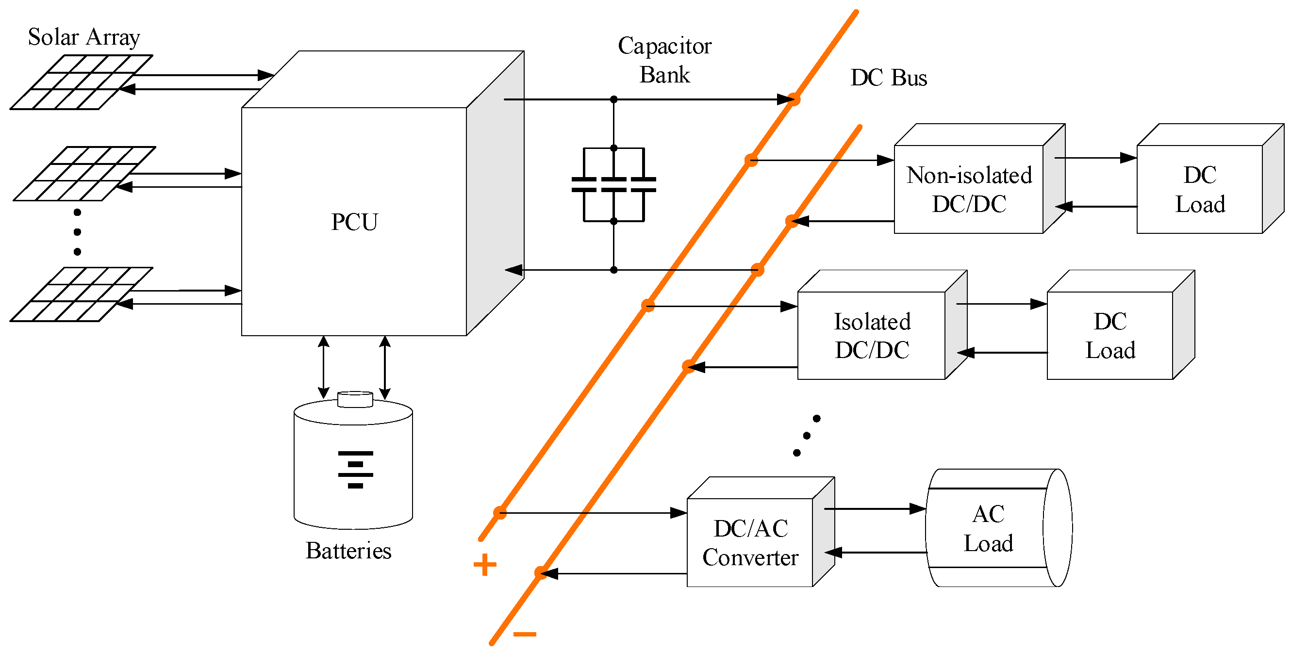
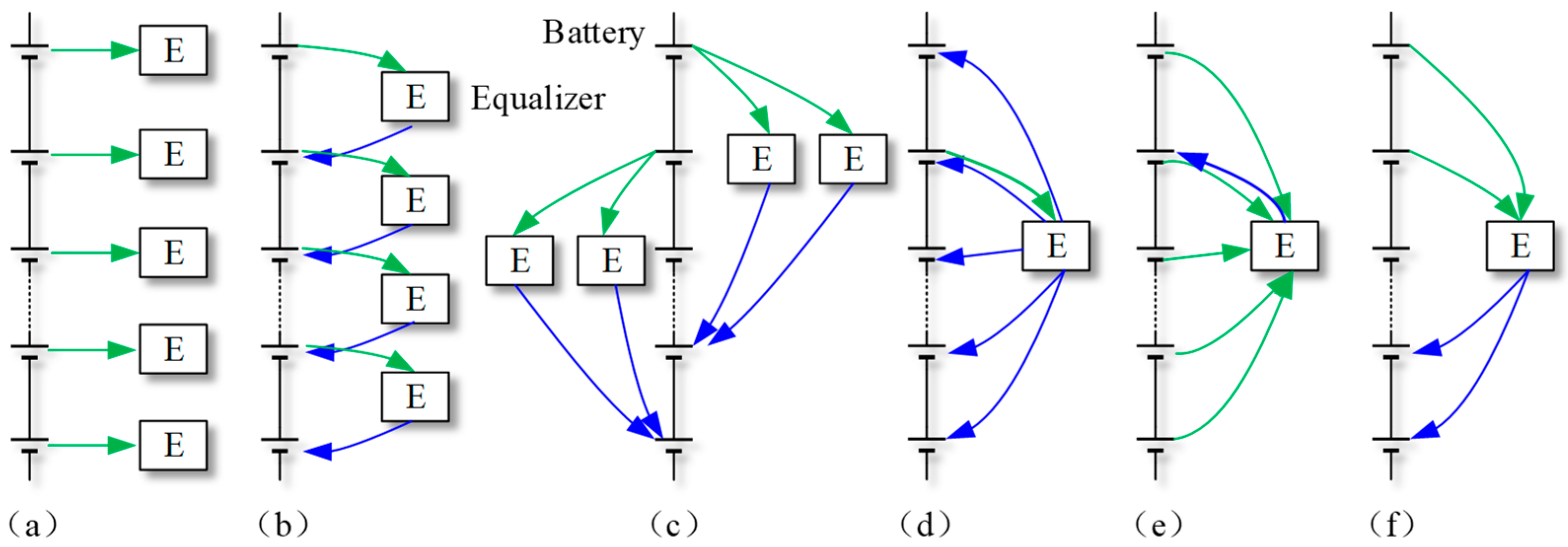
2. Battery Equalization Methods for Low-Earth Orbit Satellites
3. Topology Constructure
- LEO satellites have a short orbital period [16]. The orbital period of LEO satellites is about 100 min, and the illumination period is also short, about 1 h. Lithium batteries can be charged for a short time, so it is necessary to keep a large current in a short time to store electric energy quickly. It is simpler and more efficient to use bypass resistance equalization under the condition of high current. If active equalization is used, it is necessary to isolate the converter with high power, which is inefficient and affects reliability. In addition, in the lighting stage, the designed power of the solar cells on the satellite is greater than the power required by the system, and the bus regulator will short-circuit the excess solar cells so that electric energy can be converted into heat energy and radiated into space. Therefore, charging equalization does not need to consider efficiency, and passive equalization is enough to meet the requirements.
- Lithium batteries have many charge and discharge cycles [23]. LEO satellites have more than 5000 shadow periods every year, and the charging and discharging cycles have a great influence on the battery life, and the cycle life of lithium batteries is only about 1000 times. Passive equalization can only achieve charge equalization. Although LEO satellites rarely completely discharge batteries, adding active equalization during discharge can effectively control the discharge depth of lithium batteries, keep the attenuation of each battery cell consistent, and optimize the life of lithium batteries. Especially at the end of the design life of the satellite, when both solar cells and lithium batteries decay to a certain extent, discharge equalization can maximize the energy stored in the battery pack and maintain the normal operation of the satellite system. Active equalization can be designed with low power, and the equalization current can be about C/5, which can achieve good results.
4. Working Principle
4.1. Working Process
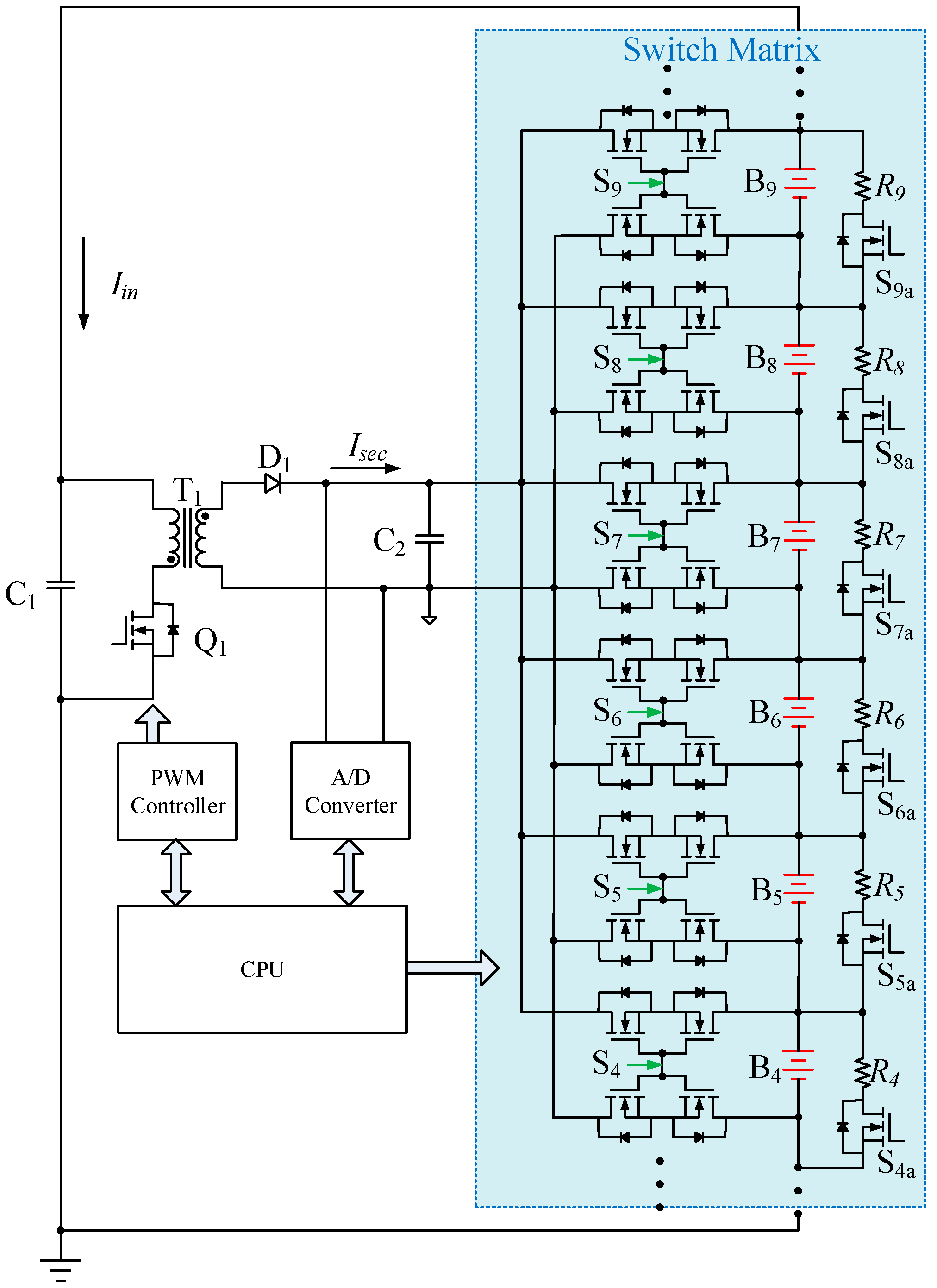
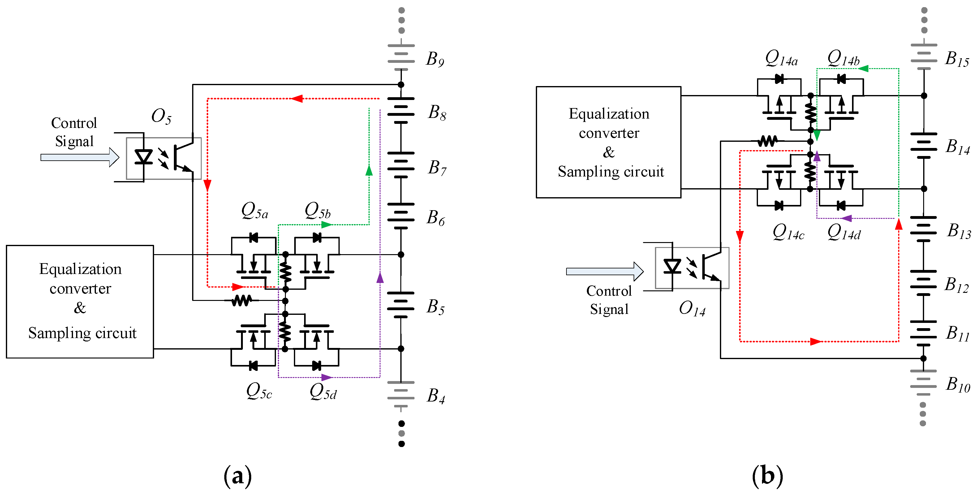
- Charging-Phase Balancing (Passive Mode): During charging, the system employs a passive balancing strategy to ensure uniform cell voltages and prevent overcharging. Each cell is continuously monitored, and when the nth cell reaches the predefined cutoff voltage (e.g., 4.2 V for Li-ion), its corresponding bypass switch Sna is activated. This connects the cell to a shunt resistor Rn, diverting excess charging current and stabilizing the voltage within safe limits. The process operates sequentially: once a cell is bypassed, charging continues for the remaining cells until all bypass switches are closed, indicating a full charge of the entire pack. This approach minimizes complexity and aligns with conventional passive balancing practices, as illustrated in Figure 4.
- 2.
- Standby/Discharging-Phase Balancing (Active Mode): In standby or discharge states, the system transitions to an active balancing mechanism to address voltage imbalances dynamically. The monitoring circuit identifies the cell with the lowest voltage (e.g., Cell n), and a switch matrix reconfigures to connect this cell to the output of a flyback-based DC-DC converter. The converter, powered by the entire pack voltage, transfers energy from the pack to the low-voltage cell, compensating for its reduced state of charge (SoC). This process iterates until all cells achieve voltage consistency, maximizing usable capacity during discharge. The active balancing workflow is detailed in Figure 4, emphasizing energy-efficient redistribution without resistive losses.
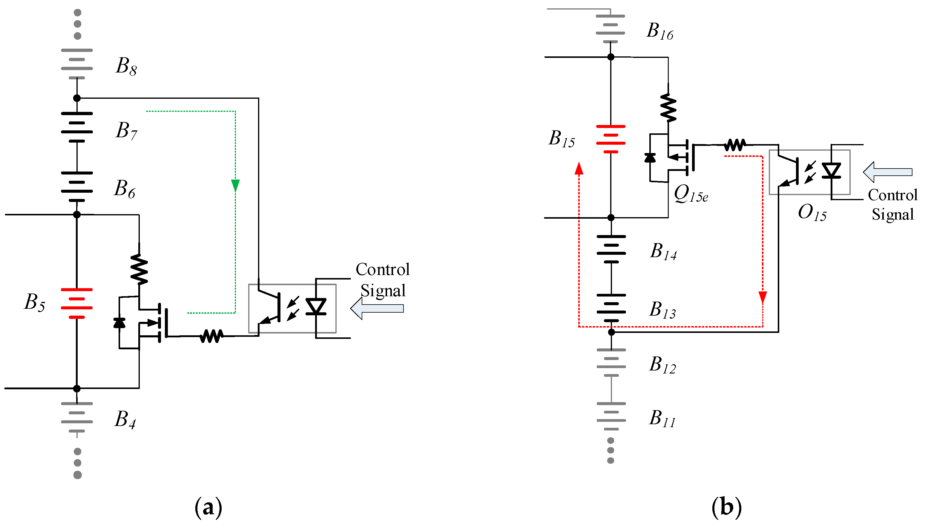
4.2. Driving of Switch Matrix
4.3. Equalization Converter Design
4.4. Equalization Time Analysis
- The equalization control system can predict the equalization time through (5), adjust the optimized equalization algorithm in real time, and improve the equalization speed.
- By increasing the power of the equalization converter, the equalization time can be reduced.
- The influence of the efficiency of the switching power supply on the equalization time decreases with the increase in the number of battery cells.
5. Experimental Results and Discussion
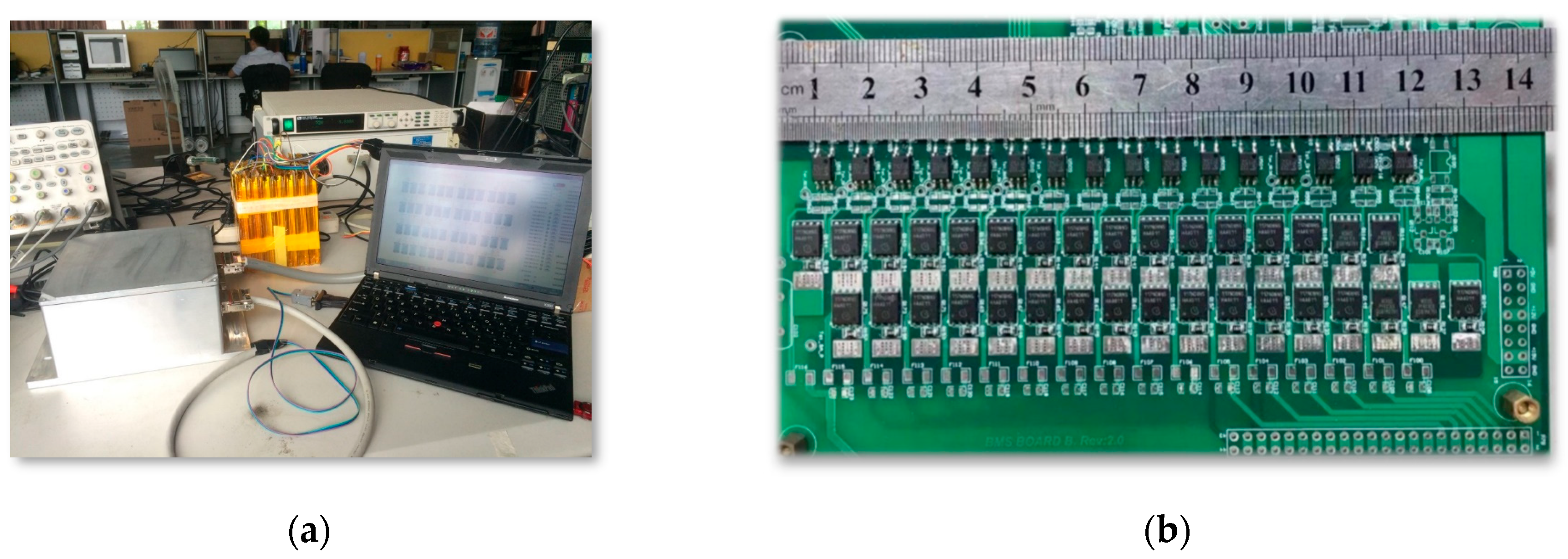
5.1. Introduction of the Prototype
5.2. Performance Verification
- (1)
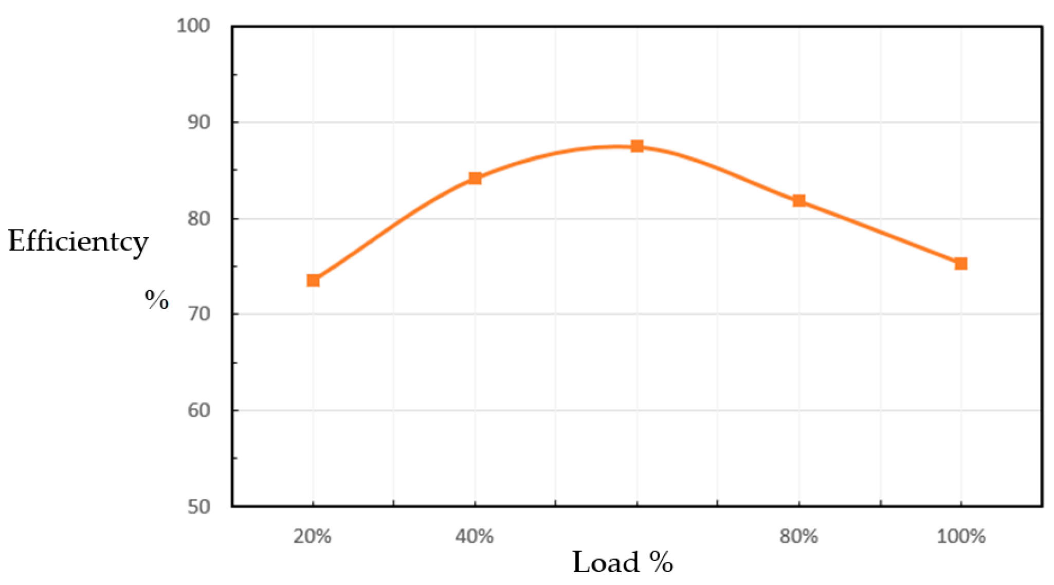
- Converter performance
- (2)
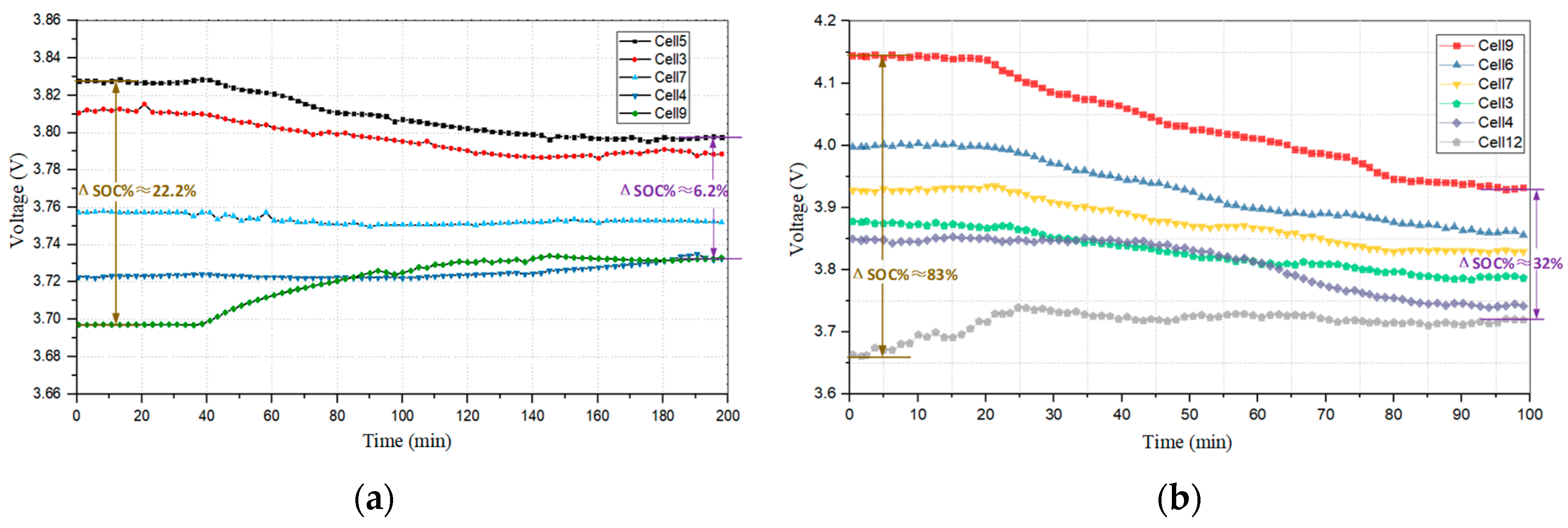
- Unbalanced system test
- (3)
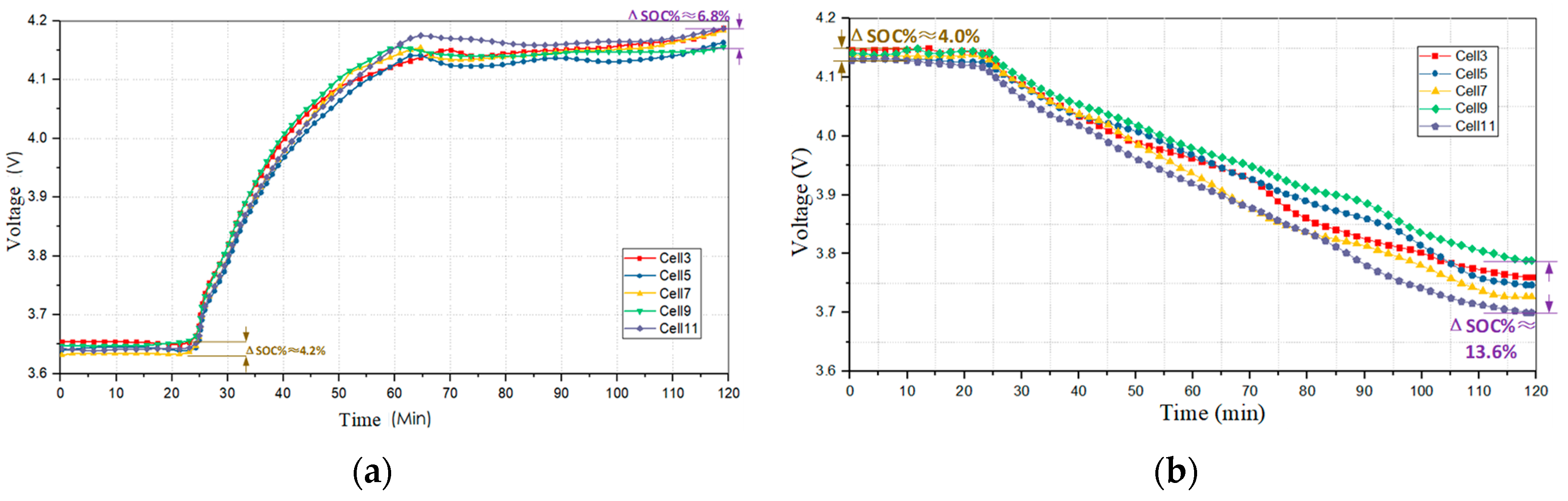
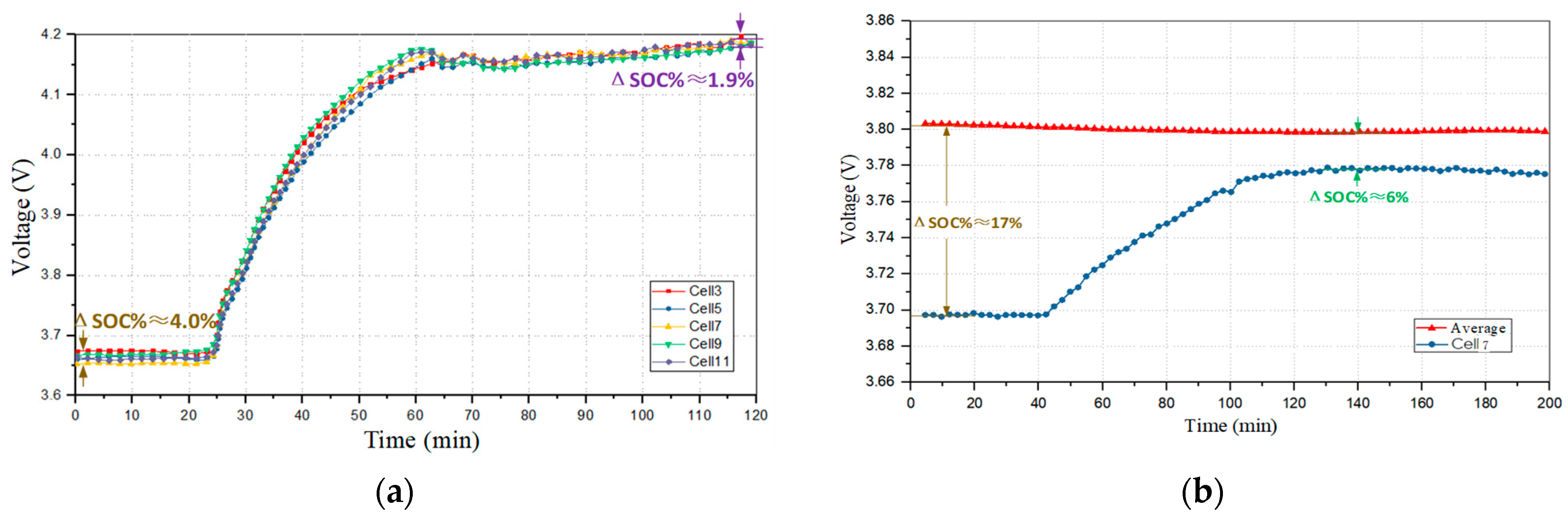
- Charge equalization test
- (4)
- Discharge equalization test
6. Conclusions
Author Contributions
Funding
Data Availability Statement
Conflicts of Interest
References
- Cao, J.; Schofield, N.; Emadi, A. Battery balancing methods: A comprehensive review. In Proceedings of the 2008 IEEE Vehicle Power and Propulsion Conference, Harbin, China, 3–5 September 2008; pp. 1–6. [Google Scholar]
- Karmakar, S.; Bohre, A.K.; Bera, T.K. Recent Advancements in Cell Balancing Techniques of BMS for EVs: A Critical Review. IEEE Trans. Ind. Appl. 2025, 61, 3468–3484. [Google Scholar] [CrossRef]
- Moore, S.W.; Schneider, P.J. A Review of Cell Equalization Methods for Lithium Ion and Lithium Polymer Battery Systems. In Proceedings of the SAE 2001 World Congress, Detroit, MI, USA, 5–8 March 2001; pp. 1–5. [Google Scholar]
- Daowd, M.; Omar, N.; Van Den Bossche, P.; Van Mierlo, J. Passive and active battery balancing comparison based on MATLAB simulation. In Proceedings of the 2011 IEEE Vehicle Power and Propulsion Conference, Chicago, IL, USA, 6–9 September 2011; pp. 1–7. [Google Scholar]
- Yu, Y.; Saasaa, R.; Khan, A.A.; Eberle, W. A Series Resonant Energy Storage Cell Voltage Balancing Circuit. IEEE J. Emerg. Sel. Top. Power Electron. 2020, 8, 3151–3161. [Google Scholar] [CrossRef]
- Shang, Y.; Zhang, Q.; Cui, N.; Duan, B.; Zhou, Z.; Zhang, C. Multicell-to-Multicell Equalizers Based on Matrix and Half-Bridge LC Converters for Series-Connected Battery Strings. IEEE J. Emerg. Sel. Top. Power Electron. 2020, 8, 1755–1766. [Google Scholar] [CrossRef]
- Wan, L.; Chen, Y.; Zhou, Y. Design of Balanced Charging Circuit for Lithium Ion Battery. In Proceedings of the 2019 Chinese Control Conference (CCC), Guangzhou, China, 27–30 July 2019; pp. 6476–6480. [Google Scholar]
- Kirbis, G.; Selcan, D.; Kos, M.; Kramberger, I. High Performance Autonomous Charge Equalization in Series Connected Batteries. IEEE Trans. Aerosp. Electron. Syst. 2019, 55, 95–107. [Google Scholar] [CrossRef]
- Roy, D.; Narayanaswamy, S.; Pröbstl, A.; Chakraborty, S. Multi-Stage Optimization for Energy-Efficient Active Cell Balancing in Battery Packs. In Proceedings of the 2019 IEEE/ACM International Conference on Computer-Aided Design (ICCAD), Westminster, CO, USA, 4–7 November 2019; pp. 1–8. [Google Scholar]
- Manjunath, K.; Kalpana, R.; Singh, B. A Modularized Two-Stage Active Cell Balancing Topology With Reduced Balancing Time for Series Connected Li-Ion Battery String. IEEE Trans. Ind. Appl. 2025, 61, 502–514. [Google Scholar] [CrossRef]
- Shang, Y.; Cui, N.; Duan, B.; Zhang, C. A Global Modular Equalizer Based on Forward Conversion for Series-Connected Battery Strings. IEEE J. Emerg. Sel. Top. Power Electron. 2018, 6, 1456–1469. [Google Scholar] [CrossRef]
- Al-Smadi, M.K.; Abu Qahouq, J.A. Evaluation of Current-Mode Controller for Active Battery Cells Balancing with Peak Efficiency Operation. IEEE Trans. Power Electron. 2023, 38, 1610–1621. [Google Scholar] [CrossRef]
- Zhao, Z.; Hu, H.; He, Z.; Iu, H.H.C.; Davari, P.; Blaabjerg, F. Power Electronics-Based Safety Enhancement Technologies for Lithium-Ion Batteries: An Overview From Battery Management Perspective. IEEE Trans. Power Electron. 2023, 38, 8922–8955. [Google Scholar] [CrossRef]
- Nie, J.; Fu, R.; Cai, C.; Ma, J.; Shu, Z.; Ma, L. A High Efficiency Battery Equalizing Circuit Based on Half Bridge Topology with Multiport Transformer. IEEE Trans. Ind. Electron. 2024, 71, 2522–2532. [Google Scholar] [CrossRef]
- Hoekstra, F.S.J.; Bergveld, H.J.; Donkers, M.C.F. Optimal Control of Active Cell Balancing: Extending the Range and Useful Lifetime of a Battery Pack. IEEE Trans. Control Syst. Technol. 2022, 30, 2759–2766. [Google Scholar] [CrossRef]
- Zhang, J.; Wu, H.; Xing, Y.; Hu, H.; Cao, F. Power management of a modular three-port converter-based spacecraft power system. IEEE Trans. Aerosp. Electron. Syst. 2016, 52, 486–492. [Google Scholar] [CrossRef]
- Astudillo, G.D.; Beiranvand, H.; Cecati, F.; Werlich, C.; Würsig, A.; Liserre, M. Integrated Strategy for Optimized Charging and Balancing of Lithium-Ion Battery Packs. IEEE Trans. Transp. Electrif. 2025, 11, 4980–4991. [Google Scholar] [CrossRef]
- Lee, W.C.; Drury, D.; Mellor, P. Comparison of passive cell balancing and active cell balancing for automotive batteries. In Proceedings of the 2011 IEEE Vehicle Power and Propulsion Conference, Chicago, IL, USA, 6–9 September 2011; pp. 1–7. [Google Scholar]
- Kong, Z.-G.; Zhu, C.-B.; Lu, R.-G.; Cheng, S.-K. Comparison and evaluation of charge equalization technique for series connected batteries. In Proceedings of the 2006 37th IEEE Power Electronics Specialists Conference, Jeju, Republic of Korea, 18–22 June 2006; pp. 1–6. [Google Scholar]
- Yang, Q.; Yang, Y.; Li, R.; Dou, Y.; Dong, B.; Yang, A. An Analog-Device-Based Five-Domain Control Method and Distributed System Configuration for High-Power Spacecraft Power Systems. IEEE J. Emerg. Sel. Top. Power Electron. 2022, 10, 5332–5344. [Google Scholar] [CrossRef]
- Andrea, D. Battery Management Systems for Large Lithium Ion Battery Packs; Artech House: Norwood, MA, USA, 2010. [Google Scholar]
- Kristiansen, B.A.; Gravdahl, J.T.; Gros, S.; Johansen, T.A. Energy Optimal Attitude Control and Task Execution for a Solar-Powered Spacecraft. IEEE Trans. Control Syst. Technol. 2024, 32, 1212–1225. [Google Scholar] [CrossRef]
- Patel, R.M. Spacecraft Power Systems; CRC Press: Boca Raton, FL, USA, 2005. [Google Scholar]
- Kim, M.; Kim, C.-H.; Kim, J.-H.; Moon, G.-W. A Chain Structure of Switched Capacitor for Improved Cell Balancing Speed. IEEE Trans. Ind. Electron. 2014, 61, 3989–3999. [Google Scholar] [CrossRef]
- Shang, Y.; Zhang, C.; Cui, N.; Guerrero, J.M. A cell-to-cell battery equalizer with zero-current switching and zero-voltage gap based on quasi-resonant LC converter and boost converter. IEEE Trans. Power Electron. 2014, 30, 3731–3747. [Google Scholar] [CrossRef]
- Shin, J.; Seo, G.-S.; Chun, C.-Y.; Cho, B.-H. Selective flyback balancing circuit with improved balancing speed for series connected Lithium-ion batteries. In Proceedings of the 2010 International Power Electronics Conference—ECCE ASIA, Sapporo, Japan, 21–24 June 2010; pp. 1180–1184. [Google Scholar]


| Parameter | CALB LP2778102 |
|---|---|
| Chemistry | Lithium Nickel Manganese Cobalt Oxide (NMC) |
| Nominal Voltage | 3.7 V |
| Capacity (Per Cell) | 2.8 Ah |
| Cycle Life (80% DoD) | 1200 cycles |
| Operating Temp. | −30 °C to +55 °C |
| Configuration in Study | 16S (16 cells in series) |
| Total Pack Voltage | 59.2 V (3.7 V × 16) |
| Dimensions (Per Cell) | 27.8 × 78 × 102 mm |
| Weight (Per Cell) | 420 g |
Disclaimer/Publisher’s Note: The statements, opinions and data contained in all publications are solely those of the individual author(s) and contributor(s) and not of MDPI and/or the editor(s). MDPI and/or the editor(s) disclaim responsibility for any injury to people or property resulting from any ideas, methods, instructions or products referred to in the content. |
© 2025 by the authors. Licensee MDPI, Basel, Switzerland. This article is an open access article distributed under the terms and conditions of the Creative Commons Attribution (CC BY) license (https://creativecommons.org/licenses/by/4.0/).
Share and Cite
Zhu, L.; Liu, Z.; Lin, Y.; Li, Z.; Qin, J.; Jin, X.; Yan, S. Li-Ion Battery Active–Passive Hybrid Equalization Topology for Low-Earth Orbit Power Systems. Energies 2025, 18, 2463. https://doi.org/10.3390/en18102463
Zhu L, Liu Z, Lin Y, Li Z, Qin J, Jin X, Yan S. Li-Ion Battery Active–Passive Hybrid Equalization Topology for Low-Earth Orbit Power Systems. Energies. 2025; 18(10):2463. https://doi.org/10.3390/en18102463
Chicago/Turabian StyleZhu, Lin, Zihua Liu, Yong Lin, Zhe Li, Jian Qin, Xiaoguang Jin, and Shujie Yan. 2025. "Li-Ion Battery Active–Passive Hybrid Equalization Topology for Low-Earth Orbit Power Systems" Energies 18, no. 10: 2463. https://doi.org/10.3390/en18102463
APA StyleZhu, L., Liu, Z., Lin, Y., Li, Z., Qin, J., Jin, X., & Yan, S. (2025). Li-Ion Battery Active–Passive Hybrid Equalization Topology for Low-Earth Orbit Power Systems. Energies, 18(10), 2463. https://doi.org/10.3390/en18102463