Abstract
Lightning-induced voltages on overhead distribution lines present a formidable obstacle to ensuring the reliability of power systems, evaluated through conventional numerical techniques, such as the Finite Difference Time Domain (FDTD) method and the Finite Element Time Domain (FETD) method. This study proposes a novel implementation of the Radial Basis Function-Finite Difference Time Domain (RBF-FDTD) method, extending the foundation of our previous work to address the field-to-line coupling equations governing such systems. The effectiveness and accuracy of this approach are rigorously validated through RBF-FDTD numerical simulations, applied to both horizontal and vertical configurations of a 1 km, 110 kV multi-conductor distribution line, as well as a real-world three-phase overhead line in Vietnam. In this study, the impact of various parameters, including line geometry, the presence of ground wires, and the influence of perfectly and imperfectly conducting ground, on the lightning-induced voltages are investigated. The simulation and computational results are in good agreement with findings from prior studies, underscoring the potential of the RBF-FDTD method as a robust tool of practical implications.
1. Introduction
The transmission and distribution lines are the key components in the operation of real-world power systems, providing the connection between power generation and end-user loads. Disruptions on these lines can significantly effect the stability and functionality of the entire electrical network. Transient phenomena, triggered by events such as line switching, capacitor bank energization, or lightning strikes—whether direct or induced—can distort voltage and current waveforms, compromising power quality. These transient surges, depending on their intensity and duration, may stress or breach equipment insulation, leading to failures and widespread outages. Such disruptions not only interrupt reliable power supply, but also diminish service standards and impose substantial financial losses. Consequently, precise computation of electrical transients is essential for optimizing the design of protective systems and determining appropriate insulation coordination to enhance grid resilience.
The investigation of electrical transients, spanning phenomena such as switching surges and operational anomalies [1], has long constituted a fundamental pillar of power system research. In contemporary studies, a pronounced emphasis has emerged on lightning-induced overvoltages in power distribution networks—a critical issue arising from the electromagnetic coupling between lightning discharges and overhead lines. These transient overvoltages, characterized by steep-fronted waveforms and high-magnitude impulses, present severe threats to grid reliability, equipment integrity, and protective coordination schemes. The growing emphasis on lightning-induced voltage research underscores its critical role in safeguarding modern power infrastructure, as evidenced by foundational studies on lightning interaction mechanisms [2], transient propagation models [3], and recent advancements in field measurement techniques [4,5,6], as they focus on empirical validation of transient phenomena, reinforcing the modern research landscape. The integration of smart grid technologies and renewable energy systems, such as photovoltaic installations, has heightened the need to mitigate lightning-induced transients, posing significant challenges to distribution system reliability [7,8]. Current research prioritizes multi-layered protection strategies, incorporating advanced surge arresters, optimized electromagnetic grounding systems, and innovative grounding techniques to enhance transient suppression [8,9,10]. These advancements aim to bolster the resilience of power networks against unpredictable lightning events, ensuring robust performance in increasingly complex and sensitive electrical systems.
With the rapid evolution of computational techniques and numerical methods, the computation of lightning-induced voltages has been a critical area of research, with various numerical methods developed to address the associated challenges. However, each method exhibits significant limitations that hinder its applicability in complex real-world scenarios. The first-order FDTD method, introduced by Agrawal et al. [11], offers a straightforward framework for solving field-to-line coupling equations. Nevertheless, its reliance on linear approximations results in considerable numerical errors when modeling complex transient phenomena, particularly in systems with heterogeneous structures. To mitigate these errors, the method necessitates extremely fine computational grids, significantly increasing computational costs and limiting its practicality for large-scale systems. Furthermore, its inability to effectively handle complex boundary conditions or nonlinear characteristics restricts its utility in realistic lightning-induced voltage analyses. Building on this foundation, Paolone et al. [12] proposed a second-order FDTD approach, which enhances accuracy through higher-order approximations. Despite this improvement, the method remains susceptible to numerical instability, particularly when employing non-uniform grids or modeling systems with abrupt material variations. Achieving stability and accuracy requires meticulous tuning of grid parameters and time steps, which escalates computational demands. In contrast, the wavelet-based technique developed by Antonini et al. [13] leverages multi-resolution analysis to capture the intricate characteristics of transient phenomena. While effective in certain contexts, this approach is hindered by its implementation complexity, as selecting an appropriate wavelet function and optimizing its parameters demands significant expertise. Additionally, the method exhibits limitations when applied to systems with pronounced nonlinearities or non-standard boundary conditions, often yielding suboptimal results in practical lightning-induced voltage scenarios. Although wavelets can reduce computational overhead in specific cases, processing complex structures or long-term simulations still requires substantial computational resources, diminishing its scalability. Finally, the FETD method, extensively utilized in studies by Liu [14,15] and Gong [16], offers flexibility in modeling complex geometries through finite element discretization. The accuracy of the FETD method is critically dependent on the quality of spatial and temporal discretization, governed by the number of segments () and the time step (). In both studies, coarse grids (low or large ) introduce numerical errors, particularly when modeling rapid transients such as lightning-induced voltages, resulting in inaccurate approximations of voltage and current. Conversely, fine grids (high or small ) significantly escalate computational costs, as the FETD method requires solving large algebraic systems. This trade-off between accuracy and computational burden complicates the determination of optimal discretization parameters, necessitating extensive trial-and-error and specialized expertise, thereby limiting FETD’s efficiency and practicality for large-scale applications.
Based on the above analysis, the FDTD method remains the most widely used approach for transient analysis in general and lightning-induced voltage computation in particular. The traditional FDTD method relies on two main strategies to reduce numerical errors: (i) employing Taylor series expansions for finite-difference approximations and (ii) increasing the number of discretization intervals. To overcome the limitations of these two strategies while maintaining the required level of accuracy, in our previous study [17], we proposed and demonstrated that replacing the Taylor series with RBFs significantly enhances the accuracy of the RBF-FDTD method compared to the traditional FDTD approach, even with a smaller number of discretization points.
The evolution of RBF-based numerical techniques over the past two decades has significantly advanced computational electromagnetics, with meshfree RBF methods and RBF-generated finite difference (RBF-FD) schemes emerging as powerful tools for complex field problems [18,19]. Building upon these developments, our research group introduced a novel adaptation—the RBF-FDTD method—first implemented for transient overvoltage analysis in power systems, as documented in [20,21]. Subsequent refinements generalized this framework to address diverse electromagnetic transients in power networks, establishing its versatility for time-domain simulations [17]. This work extends the RBF-FDTD approach as applied to both horizontal and vertical configurations of a 1 km, 110 kV multi-conductor distribution line, as well as a practical line in Vietnam. This study undertakes a comprehensive examination of the effects of several key parameters on lightning-induced voltages, including the geometry of the power line, ground wires, and the influence of both perfectly and imperfectly conducting ground conditions. The computational results obtained through this study demonstrate a strong consistency with findings from previous research [22,23], thereby validating the RBF-FDTD approach as a robust and reliable analytical tool for assessing lightning-induced voltages.
This paper is organized as follows: Section 2 develops the computational framework for modeling lightning electromagnetic fields and formulating the field-to-line coupling equations. In Section 3, we detail the application of the RBF-FDTD method to solve the electromagnetic field coupling equations for multi-conductor distribution lines. Section 4 provides numerical simulations, where the RBF-FDTD technique is employed to calculate lightning-induced voltages on benchmark 110 kV multi-conductor lines, as described in [22], as well as a real-world power line in Vietnam. Finally, Section 5 is a conclusion of the key findings and potential directions for future research.
2. Computational Model
2.1. Lightning Electromagnetic Field Model
In traditional modeling approaches, the lightning channel is often represented as a vertically oriented structure, as illustrated in Figure 1. To evaluate the electromagnetic fields at an observation point P in the frequency domain, one typically considers the response of a short dipole with a uniform current distribution. These fields can be computed using a set of fundamental equations, such as (1)–(3), which describe the relationship between the radiated electric and magnetic field components and the dipole source. These formulations incorporate dependencies on parameters like distance, orientation, and the electromagnetic properties of the surrounding medium. To determine the total field at point P, the contributions from infinitesimal dipoles distributed along the entire lightning channel are summed. This superposition approach provides a detailed and accurate estimation of the field behavior, effectively capturing both near-field and far-field characteristics shaped by the geometry and current distribution of the channel.
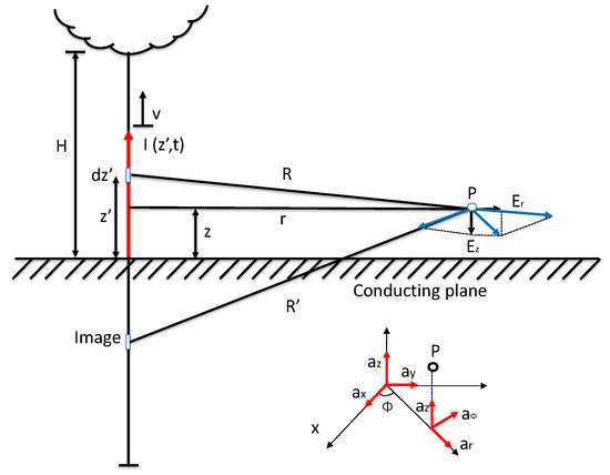
Figure 1.
Geometry model of lightning EM field.
2.1.1. Model of Barbosa–Paulino Formula
In the previous work presented by Barbosa and Paulino [24], a novel analytical expression was introduced to compute the horizontal electric field generated by a lightning channel propagating above a perfectly conducting ground, formulated in the time domain. This expression delivers results with remarkable precision, exhibiting strong agreement with those obtained through numerical evaluations of Sommerfeld integrals, which form the basis of the rigorous theoretical solution. Developed within the framework of the Transmission Line (TL) model, this approach simplifies the complex interactions between the lightning channel and the ground plane. The resulting horizontal electric field is characterized by the superposition of two distinct components, each possessing opposing polarities: one component arises from the charge distribution along the lightning channel, while the other is induced by the current flowing through it. This dual-component representation effectively captures the dynamic interplay between charge and current effects, providing a computationally efficient yet accurate tool for analyzing lightning-induced electromagnetic phenomena.
Horizontal electric field component ()
where,
- v: the propagation speed of the return stroke traveling upward along the lightning channel.
- : the return stroke speed expressed as a fraction of the speed of light, defined by .
- c: the speed of light in a vacuum, taken as .
- : the distance between the observation point and the base of the lightning channel.
- T: the front time of a trapezoidal current waveform.
- : the time it takes for the electromagnetic field to reach the observation point, calculated as .
- : the quasi-static electric field value that remains after transient components have decayed over a sufficiently long duration.
Horizontal electric field component ()
where is the magnetostatic field obtained after a long period of time
and
Total horizontal electric field component ()
2.1.2. Model of Cooray–Rubinstein Formula
In 1996, Rubinstein refined an earlier expression proposed by Cooray in 1992 [25], giving rise to what is now widely recognized as the Cooray–Rubinstein formula [26]. This formulation provides a robust method for calculating the horizontal electric field produced by a lightning channel across a range of distances—near, intermediate, and far—from the strike point. Specifically, the formula establishes a critical relationship between the horizontal electric field generated by a lightning channel propagating over a ground with finite conductivity and the corresponding electromagnetic field components over an idealized, perfectly conducting ground. These components include the horizontal electric field (expressed as the radial component in polar coordinates) and the perpendicular magnetic field. By incorporating the effects of ground conductivity and distance-dependent field behavior, the Cooray–Rubinstein formula offers a versatile and practical tool for analyzing lightning-induced electromagnetic effects, bridging theoretical rigor with real-world applicability in the study of lightning interactions with the environment.
In the works of Andreotti et al. [27,28], an enhanced version of the Cooray–Rubinstein formula was introduced, formulated in the time domain to provide an efficient and highly accurate approach for determining the horizontal electric field produced by a lightning channel. This improved formulation addresses the computational challenges posed by the Kernel integral, which exhibits a starting value of unity and does not decay to zero asymptotically. By mitigating these complexities, the method substantially simplifies numerical calculations, enabling faster processing without compromising accuracy. The streamlined implementation of this enhanced Cooray–Rubinstein formula facilitates rapid assessments of the horizontal electric field, making it a practical tool for a wide range of applications. A key advantage of this approach lies in its versatility, as it accommodates the analysis of horizontal electric fields for lightning current waveforms of arbitrary shape. This adaptability is particularly significant in the context of power system engineering, where it supports the precise estimation of lightning-induced overvoltages on transmission lines. Consequently, the formulation plays a critical role in advancing the design and optimization of robust lightning protection systems, enhancing the reliability and safety of electrical infrastructure under transient conditions.
To rigorously evaluate the Barbosa–Paulino and Cooray–Rubinstein formulas, we analyzed three representative horizontal electric field values—1000 V/m, 30 V/m, and 2.5 V/m—shown in Figure 2a–c, corresponding to high, moderate, and low lightning-induced field conditions, respectively, revealing a critical trade-off between computational efficiency and precision. At 1000 V/m, indicative of a proximate or intense lightning event, the C-R formula predicts a reduced peak of 900–950 V/m (5–10% relative error) due to its waveform smoothing and simplified treatment of soil conductivity and current transients, while the Barbosa–Paulino formula aligns closely with the observed value (<2% error), leveraging its sensitivity to rapid field variations to excel in capturing peak intensities vital for high-stakes applications, like lightning protection system design. For 30 V/m, likely from a distant strike, the C-R approach offers a stable 28–31 V/m (3–6% error), ideal for quick, large-scale simulations, whereas Barbosa–Paulino’s sensitivity to oscillations yields a slight overestimation of 32–34 V/m, providing enhanced detail that may not justify its computational cost in general-purpose modeling. At 2.5 V/m, a low-field case, Cooray–Rubinstein maintains consistency (2.3–2.6 V/m, 8% error), while Barbosa–Paulino’s refined output (2.6–2.8 V/m) offers limited advantage due to noise or parameter uncertainties, like soil permittivity. These results underscore that the Cooray–Rubinstein formula is preferable for efficient, broad-scale analyses, whereas the Barbosa–Paulino approach suits scenarios requiring high-fidelity field characterization, such as electromagnetic interference studies under varied conditions, emphasizing the need to align the chosen model with specific research objectives balancing computational feasibility and accuracy demands.
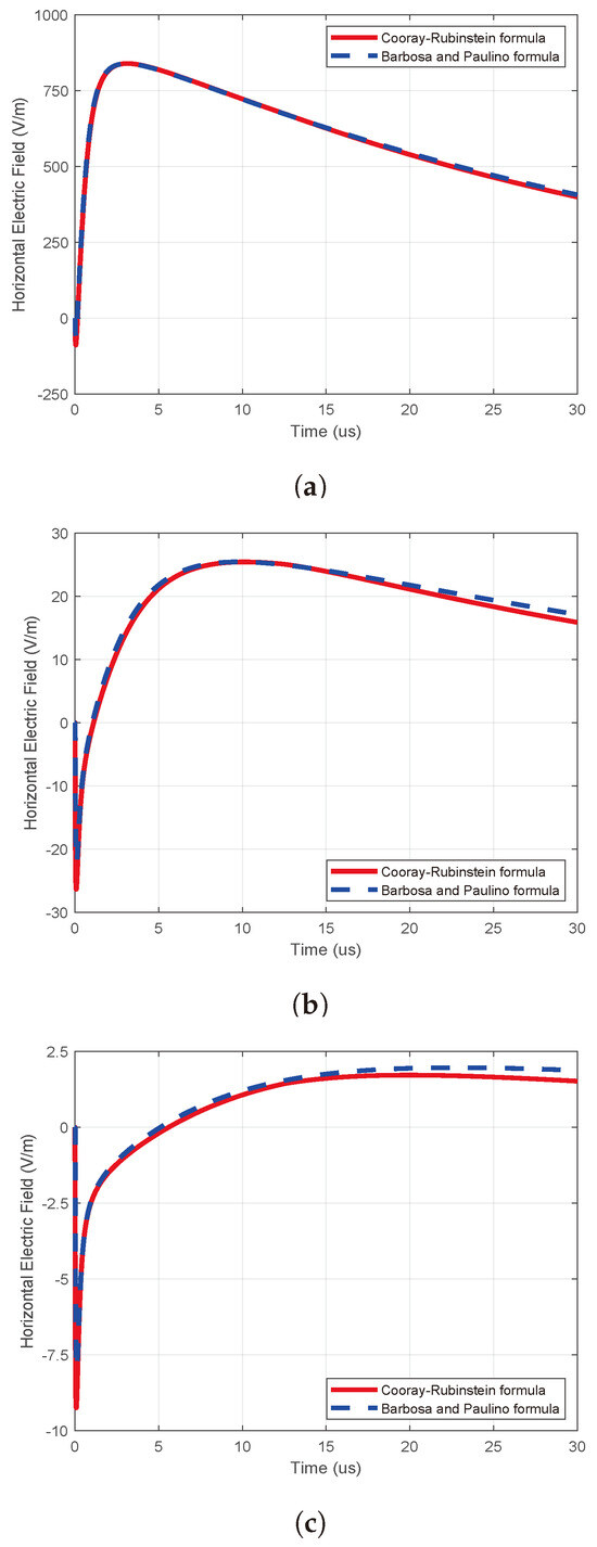
Figure 2.
The horizontal electric fields () are computed using the Barbosa−Paulino and Cooray−Rubinstein formulas: (a) = ; (b) = ; (c) = .
2.2. Field-to-Line Coupling Equations
As an initial illustration of partial differential equations (PDEs), we aim to model the transient response of a lengthy overhead distribution line subjected to external electromagnetic fields generated by nearby lightning discharges. In this study, we employ time-dependent PDEs to characterize a lossless distribution line influenced by lightning-induced electromagnetic fields. These equations, known as the field-to-transmission line coupling model, were originally developed by Agrawal et al. in 1980 [11] and are presented as follows (see Figure 3 for the geometrical parameters).
where the per-unit-length inductance and capacitance of the lines are represented by the and matrices, respectively. The scattered voltage and total current distributions along the line are described by the vectors of and . The horizontal component of the incident electric field, evaluated at the conductor height along the x-axis, is given by .
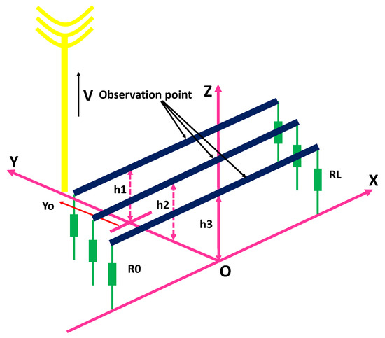
Figure 3.
Model of the geometrical parameters applied to computing lightning-induced voltages on a multi−conductor distribution line.
The total voltage induced at any point along the line is derived by combining the scattered voltage with the finite integral of the vertical incident electric field, commonly termed the incident voltage [12,22,29,30]. The relationship is expressed as:
where represents the incident voltage, and is the vertical incident electric field, assumed to be uniform across the height range of the line.
A comprehensive equivalent circuit, including both an infinitesimal segment and of the lossless transmission line, is as in Figure 4 of [22].
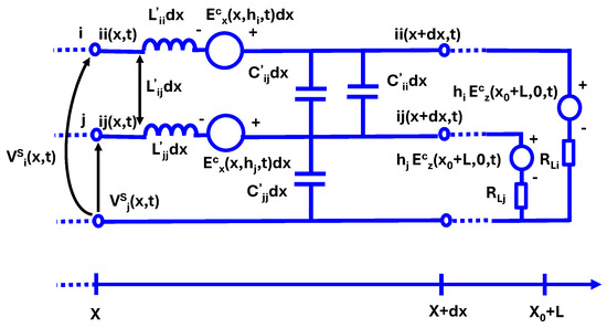
Figure 4.
Equivalent differential circuit of a lossless multi−conductor line.
3. The RBF-FDTD Method Applied to Electromagnetic Field Coupling Equations
From Equations (8) and (9), by taking the derivatives with respect to t and x on both sides, we obtain the following equations:
Rearranging these, we obtain:
Applying the Taylor expansion to the line current and the scattered voltage , we obtain:
By substituting Equations (8), (9), (13) and (14) into Equations (15) and (16) from [12], we obtain expressions for the distributed voltage and total current on the lines as
In this study, the RBF-FDTD method was employed to solve the matrix equations defined by (8) and (9). To implement this approach, one-dimensional approximations, as detailed in [17], are applied to each variable in both time t and space x. Consequently, the second-order RBF-FDTD scheme is formulated through Equations (19) and (20), providing a robust framework for analyzing transient phenomena.
We denote here:
- .
- .
- k is the kth- spatial step.
- n is the nth- time step.
- are the size of spatial and time steps, respectively.
- Nx, NT are the number of spatial and time steps, respectively.
At both ends of the line, the boundary conditions, considering the loads, are defined in terms of the scattered voltage and the total current as
where, to prevent reflections at the line terminations, the matrices and are set to match the characteristic impedance matrices of the lines.
4. Numerical Results
4.1. Case 1: Perfect Conducting Ground
Perform a simulation of lightning-induced voltage on a three-phase distribution lines using the RBF-FDTD method. We will simulate two cases: these lines arranged in a vertical configuration and in a horizontal configuration, as shown in Figure 5a and Figure 5b, respectively. For this analysis, the lightning current considered is that of a subsequent return stroke. The channel base current reaches a peak of 12 kA, with a maximum time-derivative of 50 kA/s, and the return stroke propagates at a velocity of m/s. All the remaining parameters used in this simulation are presented in Table 1.
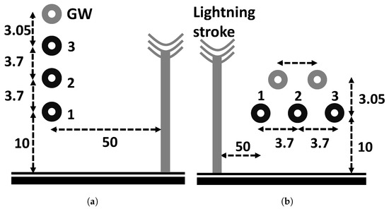
Figure 5.
Model of two distribution line configurations—ref. [22]: (a) vertical, (b) horizontal.

Table 1.
Parameters for the simulation of Case 1 and Case 2.
Here, we investigate the impact of incorporating ground wires into the three-phase line configurations previously explored. For the vertical arrangement, a single ground wire is positioned 3.05 m above the uppermost conductor, as illustrated in Figure 5a. In contrast, the horizontal setup includes two ground wires placed symmetrically 3.05 m above the three-phase conductors, as depicted in Figure 5b. The spatial arrangements mirror those examined in [22], though our simulations consider finite line lengths of 1 km, with the ground wires connected to earth at both ends of the line. The influence of these ground wires on the lightning-induced voltages across the three conductors in each configuration is presented in Figure 5a,b. The results reveal a substantial decrease in the peak induced voltage values. It is noted that grounding the ground wires at multiple points along the line, a scenario not addressed here, may introduce additional oscillations in the resulting overvoltages.
The outcomes of our simulations in Figure 6, Figure 7, Figure 8 and Figure 9 reveal a striking consistency with prior findings of Rachidi et al. [22] in the initial wavefront segment of the induced voltage profiles, yet notable differences become apparent in the wavetail portion. This observed variation can be attributed to the distinct modeling approaches employed in the calculation of lightning-induced electromagnetic fields. These differences originate from the contrasting theoretical frameworks employed to compute the electromagnetic fields induced by lightning strikes. In our study, we adopt the Transmission Line (TL) model, which assumes a uniform return stroke current and a constant propagation velocity along the lightning channel, resulting in a simplified representation of the electromagnetic field distribution along the power line. Conversely, Rachidi utilizes the Modified Transmission Line (MTL) model, which introduces a more sophisticated treatment of the lightning return stroke. The MTL model modifies the classic TL approach by incorporating an exponential decay of the current along the height of the lightning channel, typically expressed as , where z is the height along the channel and is the decay constant. Beyond these theoretical distinctions, our analysis also reveals the substantial protective influence of ground wires in both configurations under investigation. The deployment of these ground conductors significantly lowers the peak amplitude of the induced voltages, effectively reducing the transient overvoltage burden on the three-phase lines in both vertical and horizontal arrangements. This ground mechanism reinforces the vital role of ground wires in enhancing the lightning resilience of power distribution networks, mitigating the risk of damage from such high-voltage transients.
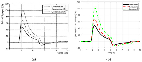
Figure 6.
Vertical configuration without ground wire: (a) result of Rachidi, (b) MQ−FDTD solution.
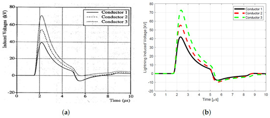
Figure 7.
Vertical configuration with ground wire: (a) result of Rachidi, (b) MQ−FDTD solution.
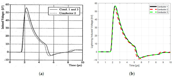
Figure 8.
Horizontal configuration without ground wire: (a) result of Rachidi, (b) MQ−FDTD solution.
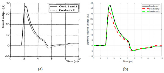
Figure 9.
Horizontal configuration with ground wire: (a) result of Rachidi, (b) MQ−FDTD solution.
4.2. Case 2: Imperfect Conducting Ground
Unraveling the complex electromagnetic interactions between lightning discharges and overhead power distribution lines is pivotal for engineering resilient lightning protection systems, particularly under realistic conditions where the ground exhibits finite conductivity rather than the idealized assumption of infinite conductivity. In practical scenarios, factors such as soil resistivity, ground impedance, and imperfect earthing significantly influence the coupling of lightning-induced electromagnetic fields with power lines, necessitating advanced analytical models beyond simplistic approximations. This challenge is adeptly met through a rigorous partial differential equation framework, meticulously developed and refined in pioneering studies by researchers, including those in [11,31,32,33], along with their collaborators. This sophisticated model encapsulates the dynamic interplay of transient electric and magnetic fields, the electrical properties of the conductors, and the dispersive characteristics of the underlying ground medium. By accounting for these parameters, it provides a robust foundation for predicting lightning-induced overvoltages, assessing surge propagation, and designing effective ground and grounding strategies tailored to the non-ideal conditions encountered in real-world power distribution networks.
The equation systems of (8) and (9) are extended as follows:
where are the convolution terms involving the time derivatives of the current vector and ground impedance functions .
The computation results illustrated in Figure 10, Figure 11, Figure 12 and Figure 13 show the influences of line configurations, ground wires, perfectly and imperfectly conducting grounds, and the distance from the lightning channel on the peak values and waveforms of lightning-induced voltages on multi-conductor distribution lines. For example, as the distance of observation increases, the peak values of the lightning-induced voltages tend to decrease, while the front-time of the corresponding waveforms increases. The peak values of lightning-induced voltages are substantially reduced by the presence of ground wires for both the center and terminal positions of the lines.
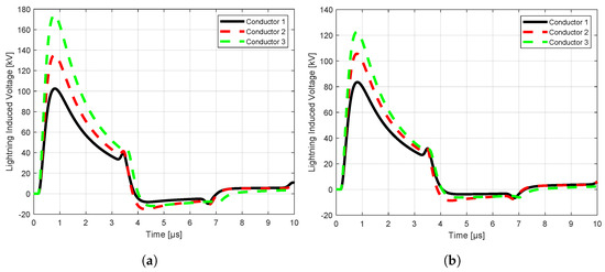
Figure 10.
MQ−FDTD solution of vertical configuration at 0 m: (a) without ground wire, (b) with ground wire.
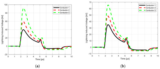
Figure 11.
MQ−FDTD solution of vertical configuration at 500 m: (a) without ground wire, (b) with ground wire.
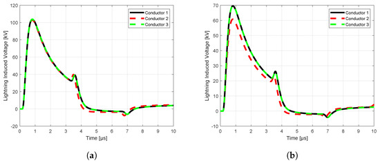
Figure 12.
MQ−FDTD solution of horizontal configuration at 0 m: (a) without ground wire, (b) with ground wire.
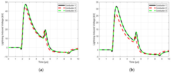
Figure 13.
MQ−FDTD solution of horizontal configuration at 500 m: (a) without ground wire, (b) with ground wire.
4.3. Case 3: The 110 kV Multi-Conductor Distribution Line in Vietnam
To apply the RBF-FDTD method to the real-world case, this study examines a 110 kV distribution line in Vietnam, which is designed with a tower-based configuration, as shown in Figure 14. The essential parameters for the simulation are comprehensively outlined in Table 2. In addition, the parameters related to the current model and the electromagnetic field of lightning are the same as those in Case 1.
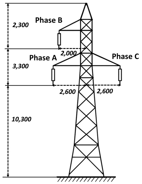
Figure 14.
Model of 110 kV distribution line in Vietnam.

Table 2.
Parameters for the simulation of Case 3.
The simulation outcomes, illustrated in Figure 15 and Figure 16, underscore the effectiveness and adaptability of the RBF-FDTD approach in modeling lightning-induced voltages on practical overhead distribution lines. These results not only validate the method’s capability to handle complex, real-world configurations, but also highlight its potential applicability to comprehensive studies of actual power systems. By accurately capturing the transient electromagnetic behavior of distribution networks subjected to lightning disturbances, the RBF-FDTD method emerges as a valuable analytical tool for assessing vulnerability and performance under extreme conditions. Furthermore, the insights derived from such high-fidelity simulations can play a pivotal role in the development of advanced lightning protection schemes, contributing significantly to the enhancement of system reliability, operational continuity, and safety across modern power infrastructures.
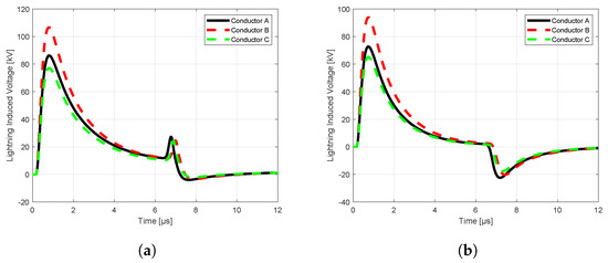
Figure 15.
MQ−FDTD solution for Case 3 at 0 m: (a) perfectly ground, (b) imperfectly ground.
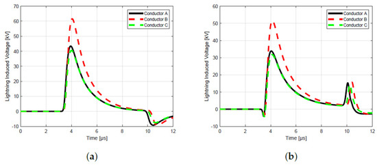
Figure 16.
MQ−FDTD solution for Case 3 at 500 m: (a) perfectly ground, (b) imperfectly ground.
5. Conclusions
This paper presents a comprehensive application of the RBF-FDTD method to the solution of the field-to-transmission line coupling equations originally formulated by Agrawal et al. [11], aimed at accurately computing lightning-induced voltages on overhead multi-conductor distribution lines. The proposed method is validated through simulations on both standardized benchmark distribution lines of [22] and a real-world three-phase power line in Vietnam, demonstrating its practical relevance and adaptability. In this study, particular emphasis is placed on analyzing the impact of various key parameters affecting lightning-induced transients. These include the presence and arrangement of overhead ground wires, different geometrical configurations of multi-conductor systems, and the electrical characteristics of both perfectly and imperfectly conducting grounds. They can be concluded as: (i) the peak value of the lightning-induced voltages on imperfectly conducting ground are approximately 25% larger than the ones of perfectly conducting ground; (ii) the peak value of the lightning-induced voltages of the line with a ground wire can decrease by a maximum of 40% compared to the ones of the line without a ground wire. For the real-world line in Vietnam, this percentage difference is about 25%. The simulation results reveal a significant influence of these factors on both the amplitude and waveform of the lightning-induced voltages. Finally, this work provides valuable insights into the electromagnetic behavior of power distribution networks under lightning conditions and offers a reliable computational framework for guiding the design of effective lightning protection strategies.
Author Contributions
Conceptualization, P.-T.V.; Methodology, P.-T.V.; Software, D.-Q.V.; Investigation, N.-N.N.; Writing—original draft, D.-Q.V.; Supervision, P.-T.V. All authors have read and agreed to the published version of the manuscript.
Funding
This research received no external funding.
Data Availability Statement
The original contributions presented in the study are included in the article, further inquiries can be directed to the corresponding authors.
Acknowledgments
We acknowledge the support of time and facilities from Ho Chi Minh City University of Technology (HCMUT), VNUHCM, for this study.
Conflicts of Interest
The authors declare no conflicts of interest.
References
- Greenwood, A. Electrical Transients in Power Systems; John Wiley and Sons: Hoboken, NJ, USA, 1991. [Google Scholar]
- Rakov, V.A.; Rachidi, F. Overview of recent progress in lightning research and lightning protection. IEEE Trans. Electromagn. Compat. 2009, 51, 428–442. [Google Scholar] [CrossRef]
- Rachidi, F. A review of field-to-transmission line coupling models with special emphasis to lightning-induced voltages on overhead lines. IEEE Trans. Electromagn. Compat. 2012, 54, 898–911. [Google Scholar] [CrossRef]
- Andreotti, A.; Araneo, R.; Faria, J.B.; He, J.; Petrache, E.; Pierno, A.; Stracqualursi, E. On the role of shield wires in mitigating lightning-induced overvoltages in overhead lines-Part I: A critical review and a new analysis. IEEE Trans. Power Deliv. 2022, 38, 335–344. [Google Scholar] [CrossRef]
- Andreotti, A.; Araneo, R.; Faria, J.B.; He, J.; Petrache, E.; Pierno, A.; Stracqualursi, E. On the role of shield wires in mitigating lightning-induced overvoltages in overhead lines-part II: Simulation results for practical configurations. IEEE Trans. Power Deliv. 2022, 38, 345–352. [Google Scholar] [CrossRef]
- La Fata, A.; Nicora, M.; Mestriner, D.; Aramini, R.; Procopio, R.; Brignone, M.; Delfino, F. Lightning electromagnetic fields computation: A review of the available approaches. Energies 2023, 16, 2436. [Google Scholar] [CrossRef]
- Cao, J.; Ding, Y.; Du, Y.; Chen, M.; Qi, R. Design consideration of the shielding wire in 10 kV overhead distribution lines against lightning-induced overvoltage. IEEE Trans. Power Deliv. 2020, 36, 3005–3013. [Google Scholar] [CrossRef]
- Mestriner, D.; Ribeiro de Moura, R.A.; Procopio, R.; de Oliveira Schroeder, M.A. Impact of grounding modeling on lightning-induced voltages evaluation in distribution lines. Appl. Sci. 2021, 11, 2931. [Google Scholar] [CrossRef]
- Zhang, X.; Huang, K. Lightning Surge Analysis for Overhead Lines Considering Corona Effect. Appl. Sci. 2021, 11, 8942. [Google Scholar] [CrossRef]
- Liu, Y.; Jiang, Y.; Gao, Q.; Li, X.; Yang, G.; Zhang, Q.; Tang, B. Influences of soil water content and porosity on lightning electromagnetic fields and lightning-induced voltages on overhead lines. Front. Environ. Sci. 2022, 10, 946551. [Google Scholar] [CrossRef]
- Agrawal, A.K.; Price, H.J.; Gurbaxani, S.H. Transient response of multiconductor transmission lines excited by a nonuniform electromagnetic field. IEEE Trans. Electromagn. Compat. 1980, 22, 119–129. [Google Scholar] [CrossRef]
- Paolone, M.; Nucci, C.A.; Rachidi, F. A New Finite Difference Time Domain Scheme for The Evaluation of Lightning Induced Overvoltages on Multiconductor Overhead Lines. In Proceedings of the International Conference on Power System Transient IPST’01, Belo Horizonte, Brazil, 7–10 June 2001. [Google Scholar]
- Pierno, A. New Approaches to Calculation of Lightning Induced Voltages on Overhead Lines for Power Quality Improvement. Ph.D. Thesis, University of Naples Federico II, Naples, Italy, 2013. [Google Scholar]
- Liu, X.; Cui, X.; Qi, L. Time-domain finite-element method for the transient response of multiconductor transmission lines excited by an electromagnetic field. IEEE Trans. Electromagn. Compat. 2011, 53, 462–474. [Google Scholar] [CrossRef]
- Liu, X.; Yang, J.; Liang, G.; Wang, L. Modified field-to-line coupling model for simulating the corona effect on the lightning induced voltages of multi-conductor transmission lines over a lossy ground. IET Gener. Transm. Distrib. 2017, 11, 1865–1876. [Google Scholar] [CrossRef]
- Gong, Y.; Hao, J.; Jiang, L.; Liu, Q.; Zhou, H. Research and application of the FETD method for the EM transient response of MTLs excited by HEMP. IET Sci. Meas. Technol. 2019, 13, 803–811. [Google Scholar] [CrossRef]
- Vu, D.Q.; Nguyen, N.N.; Vu, P.T. The RBF-FD and RBF-FDTD Methods for Solving Time-Domain Electrical Transient Problems in Power Systems. Int. Trans. Electr. Energy Syst. 2023, 2023, 6646144. [Google Scholar] [CrossRef]
- Shankar, V.; Wright, G.B.; Kirby, R.M.; Fogelson, A.L. A Radial Basis Function (RBF)-Finite Difference (FD) Method for Diffusion and Reaction–Diffusion Equations on Surfaces. J. Sci. Comput. 2015, 63, 745–768. [Google Scholar] [CrossRef]
- Uddin, M.; Ullah Jan, H.; Usman, M. RBF-FD method for some dispersive wave equations and their eventual periodicity. Comput. Model. Eng. Sci. 2020, 123, 797–819. [Google Scholar] [CrossRef]
- Vu, L.A.P.; Vu, P.T.; Ho, V.T. Calculation of Lightning-Induced Voltages on Overhead Power Lines Using the RBF-FDTD Method. In Proceedings of the 10th International Power & Energy Conference (IPEC), Ho Chi Minh City, Vietnam, 12–14 December 2012; pp. 573–577. [Google Scholar]
- Vu, P.T.; Huynh, N.B.; Nguyen, D.K. Simulation of Lightning-Transient Responses of Grounding Systems Using the RBF-FDTD Method. In Proceedings of the 10th International Power & Energy Conference (IPEC), Ho Chi Minh City, Vietnam, 12–14 December 2012; pp. 568–572. [Google Scholar]
- Rachidi, F.; Nucci, C.A.; Ianoz, M.; Mazzetti, C. Response of multiconductor power lines to nearby lightning return stroke electromagnetic field. IEEE Trans. Power Deliv. 1997, 12, 1404–1411. [Google Scholar] [CrossRef]
- Zhang, L.; Wang, L.; Yang, J.; Jin, X.; Zhang, J. Effect of overhead shielding wires on the lightning-induced voltages of multiconductor lines above the lossy ground. IEEE Trans. Electromagn. Compat. 2018, 61, 458–466. [Google Scholar] [CrossRef]
- Barbosa, C.F.; Paulino, J.O. An Approximate Time-Domain Formula for the Calculation of the Horizontal Electric Field from Lightning. IEEE Trans. Electromagn. Compat. 2007, 49, 593–601. [Google Scholar] [CrossRef]
- Cooray, V. Horizontal fields generated by return strokes. Radio Sci. 1992, 27, 529–537. [Google Scholar] [CrossRef]
- Rubinstein, M. An approximate formula for the calculation of the horizontal electric field from lightning at close, intermediate, and long range. IEEE Trans. Electromagn. Compat. 1996, 38, 531–535. [Google Scholar] [CrossRef]
- Andreotti, A.; Rachidi, F.; Verolino, L. A new formulation of the Cooray–Rubinstein expression in time domain. IEEE Trans. Electromagn. Compat. 2015, 57, 391–396. [Google Scholar] [CrossRef]
- Andreotti, A.; Rachidi, F.; Verolino, L. A new solution for the evaluation of the horizontal electric fields from lightning in presence of a finitely conducting ground. IEEE Trans. Electromagn. Compat. 2017, 60, 674–678. [Google Scholar] [CrossRef]
- Nucci, C.A.; Mazzetti, C.; Rachidi, F.; Ianoz, M. On lightning return stroke models for LEMP calculations. In Proceedings of the 19th International Conference on Lightning Protection, Graz, Austria, 25–29 April 1988; pp. 463–470. [Google Scholar]
- Rachidi, F. Formulation of the field-to-transmission line coupling equations in terms of magnetic excitation field. IEEE Trans. Electromagn. Compat. 1993, 35, 404–407. [Google Scholar] [CrossRef]
- Rachidi, F.; Nucci, C.A.; Ianoz, M.; Mazzetti, C. Influence of a lossy ground on lightning-induced voltages on overhead lines. IEEE Trans. Electromagn. Compat. 1996, 38, 250–264. [Google Scholar] [CrossRef]
- Kannu, P.; Thomas, M. Lightning induced voltages on multiconductor power distribution line. IEE Proc.-Gener. Transm. Distrib. 2005, 152, 855–863. [Google Scholar] [CrossRef]
- Cooray, V.; Rachidi, F.; Rubinstein, M. Formulation of the field-to-transmission line coupling equations in terms of scalar and vector potentials. IEEE Trans. Electromagn. Compat. 2017, 59, 1586–1591. [Google Scholar] [CrossRef]
Disclaimer/Publisher’s Note: The statements, opinions and data contained in all publications are solely those of the individual author(s) and contributor(s) and not of MDPI and/or the editor(s). MDPI and/or the editor(s) disclaim responsibility for any injury to people or property resulting from any ideas, methods, instructions or products referred to in the content. |
© 2025 by the authors. Licensee MDPI, Basel, Switzerland. This article is an open access article distributed under the terms and conditions of the Creative Commons Attribution (CC BY) license (https://creativecommons.org/licenses/by/4.0/).