Article

Enhanced Performance of a Thermoelectric Module with Heat Pipes for Refrigeration Applications

by
Majed A. Alrefae
Mechanical Engineering Department, Yanbu Industrial College, Yanbu Industrial City 41912, Saudi Arabia
Energies 2025, 18(10), 2426; https://doi.org/10.3390/en18102426
Submission received: 20 March 2025 / Revised: 2 May 2025 / Accepted: 6 May 2025 / Published: 8 May 2025
(This article belongs to the Special Issue Heat Transfer and Thermoelectric Generator)

Abstract

:
Thermoelectric module (TEM)-based coolers are gaining traction as compact, portable refrigeration solutions for storing medicine, beverages, and food. However, their adoption has been limited by relatively low cooling power and efficiency. This study demonstrates the importance of heat transfer in enhancing the coefficient of performance (COP) of TEMs through optimizing their boundary conditions. Among the three boundary conditions evaluated, the most effective involved integrating heat pipes (HPs) with a cooling fan on both sides of the TEM. This configuration significantly improved thermal management, enabling the system to achieve a COP of 0.53, with a cooling rate of 26.26 W and a cold-side temperature of 278.5 K. The enhanced heat extraction from the hot side, reaching 61.94 W, reduced the hot-side temperature to 305.6 K and decreased the overall thermal resistance, confirming the critical role of active heat dissipation. Moreover, placing a cooling fan on the HPs is crucial for facilitating efficient heat transfer from the hot side with a lower thermal resistance, as confirmed via thermal resistance analysis. Furthermore, a prototype refrigerator based on the TEM with HPs was built and tested indoors and outdoors with a COP of 0.45, a cooling rate of 21.97 W, and a cold-side temperature of 271.0 K. This study shows that the COP of TEMs can be increased by applying HPs to reduce the total thermal resistance of the TEM sides. Further optimization of TEM-based refrigerators holds promise for improving their performance in sustainable, small-scale cooling applications.

1. Introduction

A thermoelectric module (TEM) converts electrical power into both cooling and heating based on the Peltier effect [1,2]. TEMs are compact and highly reliable and exhibit precise temperature control, making them suitable for electronic, laser, and detector cooling, as well as other cooling applications [1]. Although TEMs have been used for the small-size refrigeration of food and medicine [1,3,4,5], their coefficient of performance (COP) is lower than that of Stirling and vapor compression refrigeration systems [6]. Thermoelectric modules are solid-state devices that operate with electrons as the working fluid, which eliminates the use of refrigerants with high flammability and the environmental impact of conventional vapor compression refrigerators [4]. Hence, commercial TEM-based coolers provide portable refrigeration solutions at low cooling power (less than 25 W [1]) for medicine, drink, or food storage [1,4]. The successful adoption of TEMs in small-scale cooling applications (at volumes lower than 50 L [7]) requires improved COPs at lower costs [1,4].
Upon applying direct current (DC) voltage to the TEM, one side experiences cooling (the cold side) and the other undergoes heating (the hot side) based on the current direction [1,2]. The cold side is placed inside the cooler’s compartment, whereas the hot side is exposed to the ambient environment. Effective thermal management on both sides is crucial for optimizing the COP of thermoelectric-based cooling systems [8,9,10,11]. Previous research has shown that inadequate heat rejection from the hot side adversely affects the COP, with restrictions on the achievable cold-side temperature due to heat backflow [10,11,12].
Several researchers have developed TEM-based refrigerators with various methods of heat dissipation from the hot side to improve the COP [13]. As surveyed by Hu and Shen, the majority of previous studies implemented fan-equipped heat sinks [14]. For example, Güler and Ahiska implemented these to develop a 2.25 L portable medical cooler to store medicines in the temperature range of 6–10 °C [7]. In addition, Dai et al. constructed a TEM-based refrigerator with a heat sink on the hot side to yield a COP of 0.3, a cooling rate of 12 W, and a cold-side temperature of 5 °C in three hours [15]. Similarly, Abdul-Wahab et al. reported a TEM-based refrigerator connected to heat sinks on the hot side with a COP of 0.16 and a volume of 13.25 L [16].
Moreover, a 0.63 L refrigerator with five TEMs, operated by solar energy, provided a cooling load of 5.83 W and a COP of 0.306 by connecting the hot side to heat sinks with fans [17]. A reduction in the refrigerator’s performance was observed when the heat sinks were removed due to heat accumulation on the hot side [17]. Afshari et al. built a 22.5 L refrigerator and obtained a COP of 0.015 by studying the effects of the thickness of the heat sink base and the air velocity [18]. The refrigerator’s temperature was reduced from 11.57 °C to 9.93 °C when the base thickness was reduced from 4.5 mm to 1.5 mm at an air velocity of 7.5 m/s [18]. Also, the COP and the cooling load increased when the air velocity driven by the cooling fan was increased from 7.5 m/s to 30 m/s [18]. Çaglar applied an optimization technique to find the optimum voltages for the fans and the TEM to operate a refrigerator with heat sinks [19]. The COP and the cooler’s temperature for the optimum condition were 0.351 and 254.8 K, respectively [19]. A similar study was performed by He et al. with a 76.61 L refrigerator [20]. They noticed that the voltage of the hot-side fans had larger effects on the optimum condition of the TEM [20].
Fan-equipped heat sinks have relatively high thermal resistance, which limits the COP of TEM-based refrigerators [11]. However, Min and Rowe reported that applying heat sinks with fans on the hot side resulted in a higher COP between 0.3 and 1.1, whereas the COP dropped to 0.3 with a liquid heat exchanger on the hot side of a 115 L refrigerator [3]. A third refrigerator (40 L volume) was tested using heat exchangers on both sides of the TEM, which resulted in a COP of 0.2 [3]. They indicated that the reduced COP values for the two refrigerators with liquid heat exchangers were limited by the maximum efficiency of the Peltier modules [3]. In another study, Gökçek and Şahin implemented a minichannel water-cooling plate on the hot side of a 63 L TEM-based refrigerator [21]. They found that the COP increased from 0.19 to 0.23 when the water flow rate increased from 0.8 L/min to 1.5 L/min because of the TEM’s augmented heat removal [21]. Although liquid heat exchangers have been widely used to improve TEM performance [11,12], a few refrigeration prototypes using liquid heat exchangers have been reported [14].
Furthermore, heat pipes (HPs) have been applied on the hot side of TEM-based refrigerators in a few studies [14]. For example, the use of HPs on the hot side of a TEM yielded a COP value of 0.297 for a refrigerator with a volume of 21.6 L [22]. Also, Ohara et al. constructed a 0.83 L TEM-based refrigerator for vaccine storage and obtained a COP of around 0.3 at an input power of 15.4 W using a planar HP on the hot side [23]. Vián and Astrain developed a 225 L refrigerator by applying a thermosyphon to the hot side of the TEM to increase the COP to 0.45, which was 66% higher than that obtained using heat sinks [24].
Among these heat dissipation techniques, HPs are particularly appealing for heat rejection in TEMs because of their passive nature and efficient heat transfer [25]. HPs function as two-phase flow devices operated by the capillary and vapor pressure of a working fluid in a wick structure [25,26]. The HPs comprise an evaporator, condenser, and adiabatic section connecting the two components [25,26]. The heat from the hot side raises the evaporator temperature, causing the fluid to vaporize and move to the condenser through the middle adiabatic section due to the increased vapor pressure [25,26]. The vapor condenses in the condenser. Subsequently, the liquid returns to the evaporator because of the capillary pressure [25,26,27]. This HP process facilitates continuous heat rejection from the hot side, driving fluid circulation [25]. For instance, Liang et al. reported a 42% increase in the COP of a thermoelectric system after HPs were used, attributing the improvement to a decrease in the hot-side temperature [28]. Similarly, Liu and Su studied various heat dissipation methods and found that fan-based HPs on the hot side offered the highest COP [29]. However, the effects of placing HPs on the cold side to develop TEM-based refrigerators have not been extensively studied [13].
For a better comparison with conventional vapor compression refrigerators and successful adoption in small portable cooling applications, TEM-based refrigerators should be attached to heat exchangers with minimized thermal resistances. The optimization of the boundary conditions of TEM-based refrigeration systems has been under-researched [3], in that most studies have reported the performance of TEMs with one heat exchanger design on each side [13,14]. In this study, a TEM-based refrigerator was developed by systematically optimizing three thermal boundary conditions on both sides of the module to enhance the COP. A comprehensive thermal resistance analysis was carried out to evaluate the impact of three heat dissipation strategies, revealing the critical role of boundary condition management in maximizing system efficiency.
Although TEM-based refrigerators are portable with high potential for outdoor usage (e.g., to transport medicine [5,7,23] or food [30,31]), their performance outdoors has been undertested [32]. In this work, a compact prototype refrigerator incorporating the optimized HP setup was built and rigorously tested under both indoor and outdoor conditions. The performance evaluation demonstrated the design’s robustness to varying ambient environments, underscoring the potential of boundary condition engineering to drive a new generation of high-efficiency, small-scale TEM refrigeration systems.

2. Materials and Methods

A thermoelectric module (TEC-12706, 40 mm × 40 mm × 3.7 mm) was positioned between two axially grooved HPs (AGHPs) (AX 120 SE, Thermalright Inc., Taipei, Taiwan), as illustrated in Figure 1. Each HP assembly consisted of four pipes (6 mm in diameter) embedded in an aluminum (Al) plate and extended to a height of 148 mm. Fifty Al fins (120 mm × 45 mm, with 2 mm spacing) were connected to the HPs. The HPs were tightly attached to the TEM after applying graphitic paste to lower the thermal contact resistance. A 120 mm × 120 mm fan operating at 12 V DC with an air speed of approximately 2 m/s was mounted on the HPs.
The TEM was operated at 12 V DC, and its maximum current was 6 A. A surface-contact K-type thermocouple (TL0225, Perfect Prime, London, UK) was placed between the TEM sides and the HPs to measure their temperatures. In addition, the air temperature near the edge of the HPs on both sides was measured using a K-type thermocouple (Perfect Prime). The surface thermocouple, which had a probe area of approximately 1 mm2, was flat to minimize the gap between the TEM side and HPs. For both types of thermocouples, their places remained at the same position for all experiments to eliminate dislocation effects in the results. These thermocouples were connected to a data logger (4ch K SD logger, Gain Express, Hong Kong, China) at a sampling rate of one sample per minute. The uncertainty of the temperature measurements was approximately ±3 K. Three experiments were performed for each configuration, and the measured temperatures were used to calculate the COP, heat transfer rates, and thermal resistances.
For the two configurations studied in this work, a liquid heat exchanger with an Al cooling plate (thickness of 11 mm and area of 40 mm × 40 mm) was placed on the cold side of the TEM (instead of the HPs), as explained in the previous study [33]. In this case, water flowed from a 6 L insulated tank to the cooling plate through a polyvinyl chloride (PVC) tube (1.5 mm thickness and 8 mm inner diameter) at a flow rate of 2.84 × 10⁻⁵ m3/s using a pump (12 V DC). Water exited the cooling plate and flowed to a heat exchanger with a fan (area of 275 mm × 120 mm). A surface-contact thermocouple (K-type) was included between the cold side and the Al cooling plate, and graphitic thermal paste was applied at the interface to improve heat transfer.

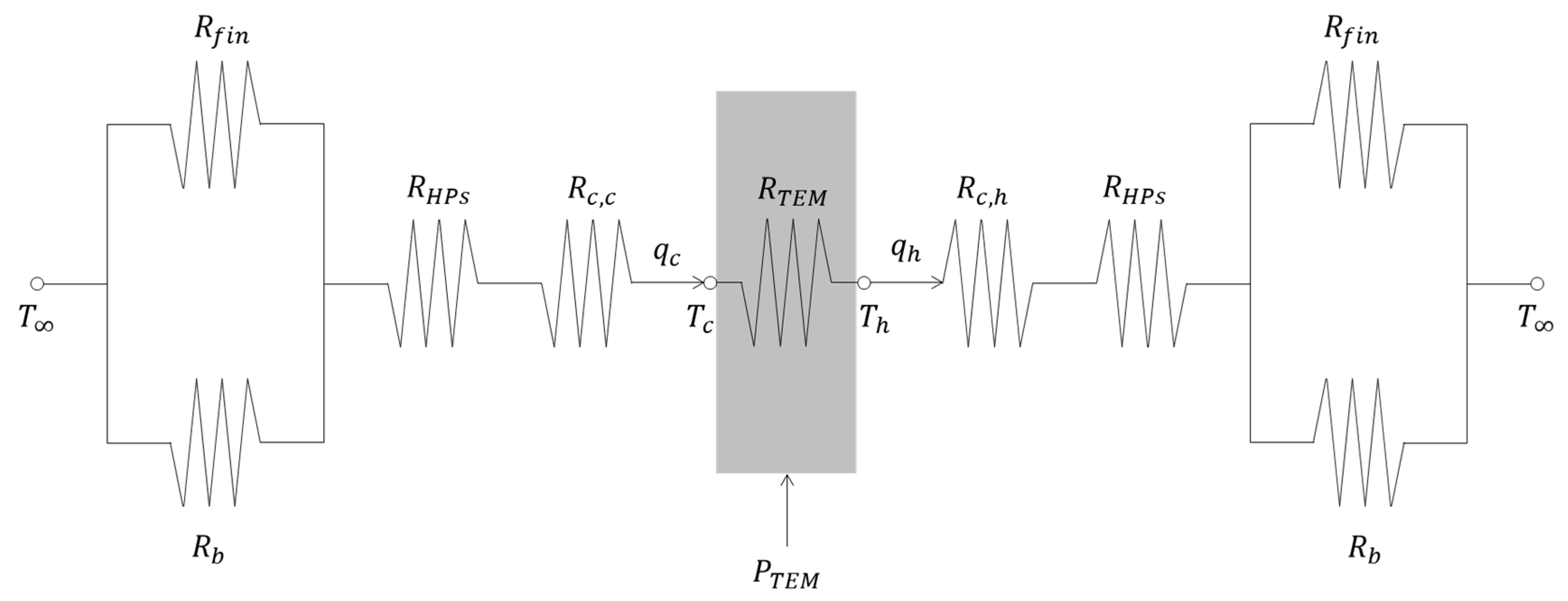
3. Heat Transfer Equations

In the steady-state and one-dimensional analysis of the TEM, the heat transfer rates out of the hot side ( q h ) and into the cold side ( q c ) are expressed as follows [34]:
q h = I S T h + 1 2   R I 2 K T h T c
q c = I S T c 1 2 R I 2 K T h T c
where I is the current, S is the Seebeck coefficient, T h is the hot-side temperature, R is the electrical resistance of the TEM, T c is the cold-side temperature, and K is the thermal conductance of the TEM. For the TEC-12706 module, S is 0.0507 V/K, K is 0.5186 W/K, and R is 1.9591 Ω, obtained at a fixed temperature of 300 K [34]. The values of S, K, and R, which depend on temperature, are assumed to be constant in this study [34].
The terms on the right-hand side of Equations (1) and (2) represent the Peltier effect of the TEM, the Joule heating, and heat conduction in the thermoelectric material, respectively [11]. In passing a current to the TEM, the Peltier effect is induced between two dissimilar materials, generating heat on one side and absorbing heat on the other based on the thermoelectric effects [11,35]. This generated and adsorbed heat is defined by the effective Seebeck coefficient of thermoelectric materials, the current, and the corresponding side temperature as written in Equations (1) and (2) [35]. The Joule heating (or Ohmic dissipation), which is due to current flow in the thermoelectric material, is equally split to the TEM sides (i.e., half of the Joule heating transfers to the hot side and the other half to the cold side) [11]. In addition, heat conduction occurs from the hot side to the cold side because of their temperature difference [11].
The Peltier effect on the cold side (i.e., I S T c ) has to surpass both the Joule heating (i.e., 1 2 R I 2 ) and the conduction heat transfer in the TEM (i.e., K T h T c ) to increase its cooling capacity [11]. The COP of the TEM cooling system is expressed as follows [34]:
C O P = q c P
where P is the applied electrical power, P = VItot; V is the voltage, which is 12 V DC; and Itot is the total electrical current supplied to the cooling system (including the current applied to the TEM, fans, and pumps if used in the configuration). The current was measured using a clamp-on ammeter.
The hot-side thermal resistance ( R t o t , h ) includes the thermal resistances between the hot side of the TEM and the air. R t o t , h is expressed as follows [35]:
R t o t , h = T h T q h
where q h is determined using Equation (1) and T h was measured during the experiment. T is the ambient air temperature, which was measured with a value ranging between 295 and 296 K depending on the experiment. Similarly, the cold-side thermal resistance ( R t o t , c ) is given by Equation (5) [35]:
R t o t , c = T T c q c
where q c is determined using Equation (2) and T and T c were measured during the experiment.
The thermal resistance network for the TEM with HPs on both sides is shown in Figure 2. R t o t , h includes all the resistances between T h and T , which are the contact resistance on the hot side ( R c , h ), the HPs’ resistance ( R H P s ) , the fin resistance ( R f i n = 1 N η f h A f , where N is the number of Al fins, η f is the fin efficiency, h is the heat transfer coefficient, and A f is the fin surface area), and the convective resistance from the unfinned surfaces of the HPs’ condenser ( R b = 1 h A b , where A b is the unfinned surface area of the HPs’ condenser) [35,36]. Similarly, the R t o t , c includes all the resistances between T and T c , which are the contact resistance on the cold side ( R c , c ), R H P s , R f i n , and R b [35,36]. R T E M is the conduction thermal resistance of the TEM and P T E M is the electric power supplied to the TEM [35]. R H P s includes the thermal resistances of the HPs, such as the evaporator and condenser, and the walls and wick thermal resistances [36,37].

4. Results

4.1. Effects of Boundary Conditions on the TEM Performance

In Figure 3, T h and T c are shown for the TEM with HPs on the hot side and a cooling plate attached to the cold side. The temperatures stabilized rapidly after approximately one minute, with T h and T c values of 333.1 ± 0.4 K and 282.4 ± 0.3 K, respectively. The temperature difference between the TEM sides, ΔT = T h T c , was 50.6 ± 0.7 K. For this configuration, the COP was 0.25 ± 0.01, and the values of q c and q h were 11.10 ± 0.13 W and 42.48 ± 0.09 W, respectively.
However, removing the fan from the HPs increased T h significantly to 376.7 ± 2.6 K (Figure 4). In addition, T c initially dropped to 285.1 K but gradually returned to 298.1 ± 2.6 K (i.e., above the ambient temperature) after 30 min. In contrast to the results in Figure 3, where T h increased sharply with time to the asymptotic value of 333.1 K in one minute, T h (for the HPs without the fan in Figure 4) increased gradually with time and reached 376.7 K after 30 min. This temperature increase was due to the reduced heat removal of the HPs at higher condenser temperatures. This observation aligns with the findings of Riffat et al. [27], who noted a higher condenser temperature when the fan was off. Furthermore, Sun et al. observed a decrease in the cooling capacity of a TEM connected to HPs as the ambient temperature increased due to reduced heat dissipation from the condenser [38]. In another study, Sun et al. reported that higher ambient air temperatures led to increased condenser temperatures, resulting in higher temperatures on the TEM sides [39].
The increased T c resulted in heat transfer from the cold side at a rate of 6.78 ± 0.49 W (i.e., the cold side heated the environment instead of cooling it). Additionally, q h dropped to 18.69 ± 0.44 W when the fan was removed from the HPs. Therefore, the TEM did not operate effectively, and both sides transferred heat to their surroundings because the ΔT (78.6 ± 5.2 K) was above the maximum temperature difference of this module (67 K [28]). Thus, dissipating heat from the HPs is crucial for lowering the condenser temperature and improving TEM performance [27].
When the HPs were connected to the cold side (the third configuration), the T c was lowered to 278.5 ± 0.3 K with a higher q c of 26.26 ± 0.54 W, as presented in Figure 5. Furthermore, the heat rate out of the hot side was enhanced ( q h = 61.94 ± 0.32 W), which significantly reduced the T h to 305.6 ± 1.3 K. Therefore, the COP increased substantially to 0.53 using HPs on the TEM sides because of the increased heat transfer rates and reduced T h [11,27].
In this configuration, the HPs attached to the cold side are heated by ambient air, in contrast to the standard HP operation [40]. Here, the evaporator absorbs heat from the surrounding air, whereas the condenser is attached to the cold side [40]. In this study, the HPs on both sides were positioned horizontally. The vertical placement of the HPs (with the hot side up or down) had minimal impact on the TEM performance, with the temperatures remaining within the experimental uncertainty.

4.2. Characterization of a TEM-Based Cooler with Heat Pipe Assembly

Based on the optimized conditions from the heat transfer analysis of the TEM with different boundary conditions, a 12 L refrigerator was constructed using HPs with a fan configured on both sides of the TEM. The HPs on the cold side were placed inside an insulated polystyrene foam box, as shown in Figure 1b. The size and construction of the refrigerator, which allow for direct comparisons with previous studies using a similar volume range [7,15,16,17,18,22,23], offer small-scale and portable solutions for medicine, food, or drink storage and transportation [1,4,5,7,23,30,31]. The air temperature inside the insulated box was measured using three thermocouples at different locations, and the average temperature was used in the analysis. The variation between these thermocouples was less than 1 K, which was within the experimental uncertainty. Two experimental conditions were tested: one inside a laboratory with controlled ambient air temperature and humidity and the other outdoors to examine the performance under various weather conditions during the day.
Although the T h remained constant at 304.8 ± 0.1 K for the indoor experiment, similarly to the results shown in Figure 5, the T c gradually decreased to 268.7 ± 0.4 K. The values of q c and q h remained at 20.73 ± 0.36 W and 61.34 ± 0.59 W, respectively. Hence, the refrigerator temperature gradually declined from 294.5 ± 0.2 K, which was the ambient temperature inside the laboratory, to a steady-state value of 281.6 ± 0.9 K within 30 min, as shown in Figure 6. In addition, the air temperature near the hot-side HPs increased from ambient temperature to a steady-state temperature of 298.6 ± 0.7 K in approximately two minutes, as shown in Figure 6.
The COP of this refrigeration system was 0.40 ± 0.03, which was lower than the COP when the TEM was placed outside the insulated box. Internally placed, the TEM generated a reduced cooling power ( q c = 20.73 W) to reduce the T c to 268.7 K. However, a higher cooling power ( q c = 26.26 W) was necessary to reach a value of 278.5 K for the T c due to the cooling of the surroundings at 295 K. This observation agrees with the findings of Liang et al., who reported an increase in the cooling capacity of a TEM with an increase in the cold-side temperature, leading to an increased COP [28].
Abdul-Wahab et al. reported a COP of 0.16 for a TEM-based refrigerator utilizing fan-equipped heat sinks on the TEM sides [16]. Their refrigerator had a volume of 13.25 L, and the temperature on the cold side was reduced to approximately 268 K in 44 min [16], which is comparable to the results of this study. Similarly, Min and Rowe reported a 40 L refrigerator with a COP of approximately 0.2, using liquid heat exchangers on the TEM sides [3]. The air temperature inside the refrigerator decreased to approximately 278 K after approximately 80 min [3]. They also compared three TEM-based refrigerators and found that the COP increased with a reduction in thermal resistance on the TEM sides [3]. Furthermore, the use of HPs on the TEM sides in another study by Abderezzak et al. yielded a COP value of 0.297 for a refrigerator with a volume of 21.6 L, which was cooled to 276.95 K in 72 min [22]. These results indicate that the COP of TEM-based refrigerators can be increased using HPs and by reducing the total thermal resistance of the TEM sides.
Moreover, an outdoor experiment was conducted to examine the performance of the TEM-based refrigerator placed outside the laboratory in a shaded area. During the test, the relative humidity ranged between 10% and 70%, and the ambient air temperature was between 297 and 306 K. Figure 7a shows the TEM sides and ambient air temperatures throughout the experiment, which was continuously operated. Another experiment was conducted in a cyclical fashion to examine TEM operation during start-up under different weather conditions.
Both T h and T c followed the trend of T for continuous and cyclic operations. The ambient air temperature during continuous operation was lower than that when the TEM-based refrigerator was operated in cycles. Hence, the cold-side temperature for continuous operation was approximately 2 K lower than that for cyclic operation. This difference between the two experiments was reduced to approximately 1.5 K for T h . The values of T c were between 278.4 at 14:15 and 271.0 K at 23:30 for the continuous experiment because the variations in T were between 303.4 K and 296.1 K, respectively. At the same time, the maximum and minimum T h were 313.4 K and 306.3 K, respectively.
Similarly, the hot-side temperature increased sharply from ambient temperature to 310.3 K for the first and third cycles and to 315.5 K for the second cycle. The cold-side temperature decreased sharply from ambient temperature to 276.2 K, 281.2 K, and 276.6 K for the first, second, and third cycles, respectively. The values of T h and T c for both the continuous and cyclic experiments were higher compared to their corresponding values of 304.8 K and 268.7 K, respectively, when the refrigerator was placed in the laboratory.
Unlike in the results in Figure 3, Figure 4 and Figure 5, where the TEM side temperatures exhibited steady-state values, the cold- and hot-side temperatures varied during the outdoor experiment due to the changes in T , as shown in Figure 7a. The values of T h and T c increased slightly with time from 10:00 to 14:15 but then decreased gradually until reaching the lowest values during the night, following the T . However, subtracting the ambient air temperature from the hot- and cold-side temperatures shows steady values for ( T h T ) and ( T c T ) at 9.9 ± 1.7 K and −24.4 ± 3.5 K, respectively (Figure 7b). For comparison, ( T h T ) and ( T c T ) had similar values, which were 10.2 ± 1.8 K and −24.0 ± 5.0 K, respectively, when the refrigerator was placed indoors.
Similarly, q h and q c were 59.39 ± 1.08 W and 21.97 ± 0.69 W, respectively, which are close to the values when the refrigerator was indoors. Also, the COP for the refrigerator placed outdoors was 0.45 ± 0.02, which is slightly higher than that for the indoor experiment. The cooling rate and COP were slightly higher because the T was higher outdoors, which necessitated a higher cooling power than when the refrigerator was indoors. Hence, placing the refrigerator outdoors (under the weather conditions of this study) had little influence on the TEM performance in that the parameters remained the same within the experimental uncertainty.
The air temperatures inside the refrigerator and near the hot-side HPs followed the same trend of the T c and T h with T , as presented in Figure 8. The air temperature in the refrigerator when running continuously had lower values because of the lower ambient temperatures. In this case, the air temperature in the refrigerator decreased initially from 296.5 K to 285.8 K in 20 min of operation. Then, it slightly increased following the ambient temperature until reaching 289.4 K at 14:15, after which it declined to 282.4 K at the end of the experiment. A similar trend was observed for the air temperature near the hot-side HPs, with maximum and minimum temperatures of 306.4 K and 299.0 K, respectively.
These temperatures were slightly higher when the refrigerator was run in cycles because of its relatively higher ambient temperature. In the first cycle, the refrigerator temperature decreased initially from 297.6 K to 287.7 K but then increased slightly with time to 290.5 K when the ambient temperature was 303.6 K at 12:07. The refrigerator temperature continued to decrease for the second and third cycles to 289.0 K at 17:07 and 284.1 at 23:59, respectively. Hence, the refrigerator could be cooled to temperatures as low as 14.3 K below T . These values are close to those obtained when the refrigerator was placed indoors, which indicates that the refrigerator has similar performance regardless of the ambient conditions studied in this work. The refrigerator temperature can be reduced to lower values by applying more than one module or using a multistage module [28]. Nevertheless, at ambient temperatures above 306 K, the TEM performance is expected to decrease due to the increased ambient temperature. In this case, a larger condenser and higher-speed fan can aid in increasing the heat dissipation from the TEM to enhance its performance.

5. Discussion

The cold-side temperature of the module stabilizes quickly for all cases, except when there is no fan connected to the HPs, as shown in Figure 4. This rapid cooling of the TEM is an advantage of TEM-based cooling systems to allow instant temperature control in response to transient heating [41]. In addition, the thermoelectric module offers various cold-side temperatures by adjusting the thermal boundary conditions on both sides. The required cold-side temperature and cooling rate can be obtained by selecting an appropriate heat sink connected to the TEMs, offering a flexible thermal design [13].
Table 1 lists the results of these configurations, which show that the COP increases from 0.25 to 0.53 as the ΔT decreases from 50.6 K to 27.2 K, which is consistent with previous studies [11,22,28]. At a larger ΔT value of 78.6 ± 5.2 K, which is higher than the operating limit of this module (67 K [28]), the TEM does not provide cooling power in the case where the fan was removed from the HPs (Figure 4). Instead, the cold side dissipates heat to the environment due to the significant heat backflow from the hot side. Therefore, a smaller ΔT reduces the heat conduction between the TEM sides, leading to a higher q c and COP, as indicated by Equations (2) and (3), respectively [41].
Furthermore, Table 1 shows that the COP of the system increased from 0.25 to 0.53 as R t o t , h decreased from 0.87 K/W (using HPs with a fan on the hot side only) to 0.17 K/W (using HPs with a fan on both sides). The rise in the COP with the reduction in the hot-side thermal resistance is in agreement with the results reported by Min and Rowe [3]. They observed that decreasing the hot-side thermal resistance (in the range of 0.02 to 0.13 K/W) significantly improves the COP [3]. When the fan was removed from the HPs, R t o t , h increased drastically to 4.32 K/W due to the relatively high thermal resistance of free convection [11]. As the thermal resistance increased, q h was reduced, and heat backflow to the cold side occurred, increasing T c above the ambient temperature. Therefore, R t o t , h significantly affected the cooling rate and overall efficiency of the system, which is in agreement with previous results [3,42,43].
The thermal resistances lumped in R t o t , h include the contact resistance between the TEM hot side and the HPs, the HPs resistances, the resistance of the Al fins, and the resistance of the unfinned surfaces of the condenser [35,36,37], as shown in Figure 2. In the absence of forced convection driven by the fan, the thermal resistances of the fin array and the unfinned surfaces of the condenser dominate other resistances due to the reduction in the heat transfer coefficient for natural convection [11]. Hence, the value of R t o t , h is increased for the first configuration in Table 1, limiting the heat dissipation of the HPs to 18.69 W and degrading the TEM performance. On the other hand, connecting a fan to the HPs increases the heat transfer coefficient through forced convection [35] and reduces R f i n , R b , and R t o t , h , as demonstrated in the second and third configurations in Table 1 [11].
In addition, the cold-side thermal resistance affects the cooling rate and COP of the system. For instance, the values of R t o t , c were 1.22 and 0.63 K/W when the HPs with a fan were attached on the hot side and on both sides, respectively. With the HPs on the cold side, R t o t , c decreased due to the higher q c offered by the HPs. A similar trend was reported by Min and Rowe [3], who observed a significant improvement in the COP with a reduction in the cold-side thermal resistance (between 0.02 and 0.13 K/W) [3]. The reduction in R t o t , c with HPs is lower than that in R t o t , h because the HPs operate opposite to their design when placed on the cold side with a reduced condenser area [40]. Also, R t o t , h has greater influence on TEM performance than R t o t , c because q h is higher than q c at low COP values [42,43]. The low value of R t o t , c in the first configuration in Table 1 was due to the slight difference between T and T c .
Another effect of applying HPs on the cold side is the reduction in R t o t , h . A previous study showed that the value of R t o t , h could be lowered by increasing the cooling rate of the cold side [44]. The overall energy balance of the TEM (as illustrated in Figure 2) correlates q h and q c with P T E M as q h = q c + P T E M [35]. Since q h increases with q c assuming constant P T E M , connecting the HPs on the cold side increases q c and q h . As a result, both R t o t , c and R t o t , h are reduced following Equations (4) and (5), respectively.
These results demonstrate that the overall efficiency of the TEM is strongly controlled by the thermal resistance of both sides [3,45]. According to the thermal resistance analysis, the COP of the TEM increases with a reduction in the thermal resistance on the hot side. When the thermal resistance of the hot side is elevated, the thermoelectric module does not provide cooling, as shown in the case when the thermal resistance is 4.32 K/W. In this case, the heat is dissipated back to the cold side, and the TEM is dominated by Joule heating and heat conduction, as shown in Equation (2). Hence, the TEM becomes inefficient because it heats the system and degrades its overall performance. Conversely, lowering the thermal resistance on the hot side (less than or equal to 0.87 K/W in this work) enhances the overall efficiency of the system because the generated heat in the module is dissipated effectively to the environment. Hence, a lower ΔT was facilitated, as summarized in Table 1.
Natural (or free) convection with a low heat transfer coefficient limits the HPs’ operation and their heat dissipation capability and reduces the TEM performance [11]. New fan designs offer low noise with minimal power consumption and reduced cost, making them a suitable solution for TEM-based cooling systems [46]. The successful implementation of TEM technology in cooling applications necessitates connecting the hot side to an efficient heat sink to enhance heat dissipation [3]. Otherwise, thermoelectric modules are not useful due to the added cost and complexity of the cooling system.
The thermal resistance analysis shows that the optimum boundary conditions in this work involve applying HPs on both sides of the thermoelectric module with thermal resistances of 0.17 and 0.63 K/W on the hot and cold sides, respectively. These relatively low values aid in improving the TEM performance, in agreement with the findings of a previous study [13]. Further reduction in the total thermal resistance of the hot side by lowering its thermal contact resistance and increasing the convective heat transfer coefficient (using a large-area condenser or high-speed fan) enhances the overall efficiency of TEMs for cooling applications [3].

6. Conclusions

TEM-based refrigerators have been used for the storage of small amounts of medicine, drink, and food, even though their COP is low. This work applies a scalable design for TEM-based refrigeration systems by emphasizing the importance of optimizing thermal boundary conditions. Three boundary conditions on the TEM sides were studied in this work to improve the COP and contribute to the successful adoption of TEM-based coolers in small-scale applications. The main findings of this study are the following:
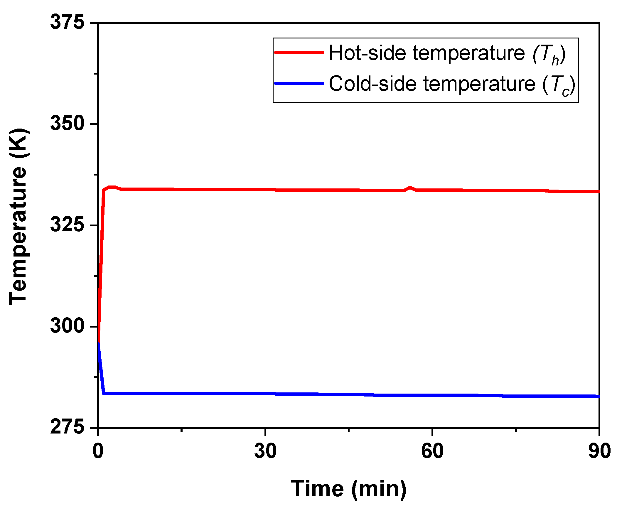
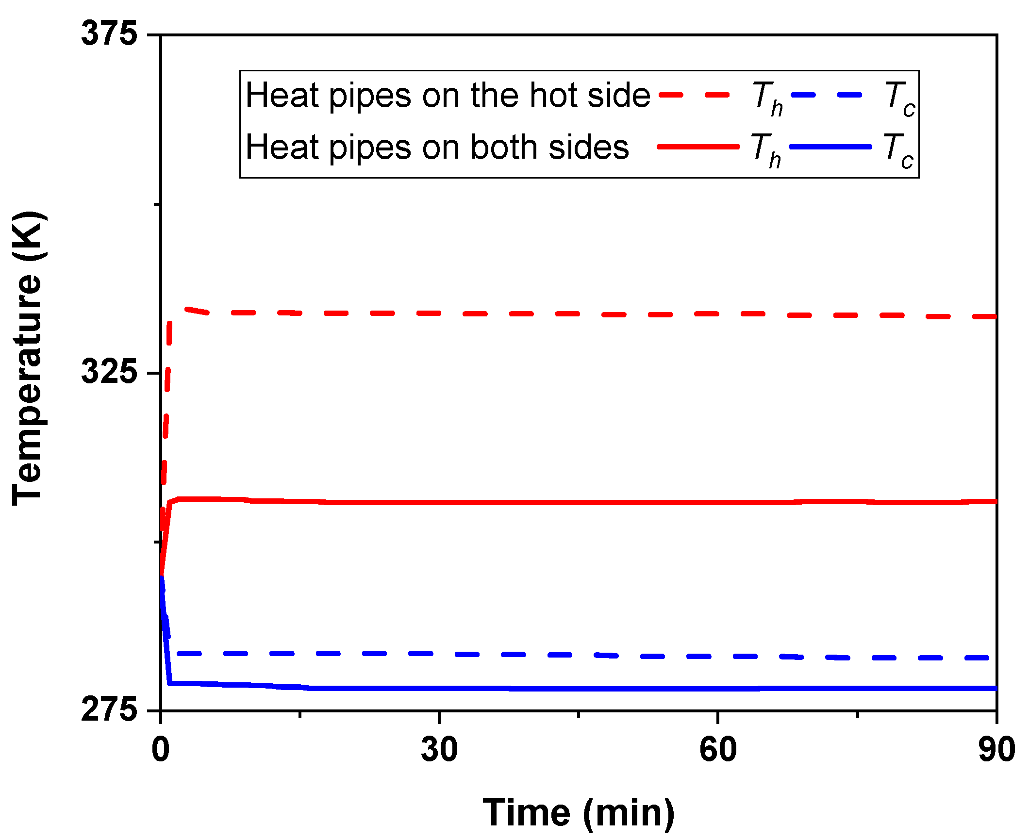
  • The optimized configuration from the three boundary conditions included HPs attached to a fan, which yielded a COP of 0.53 at a cooling rate of 26.26 W and a cold-side temperature of 278.5 K. This significant improvement in TEM performance was due to the enhanced heat transfer from the hot side (61.94 W), which reduced the hot-side temperature to 305.6 K.
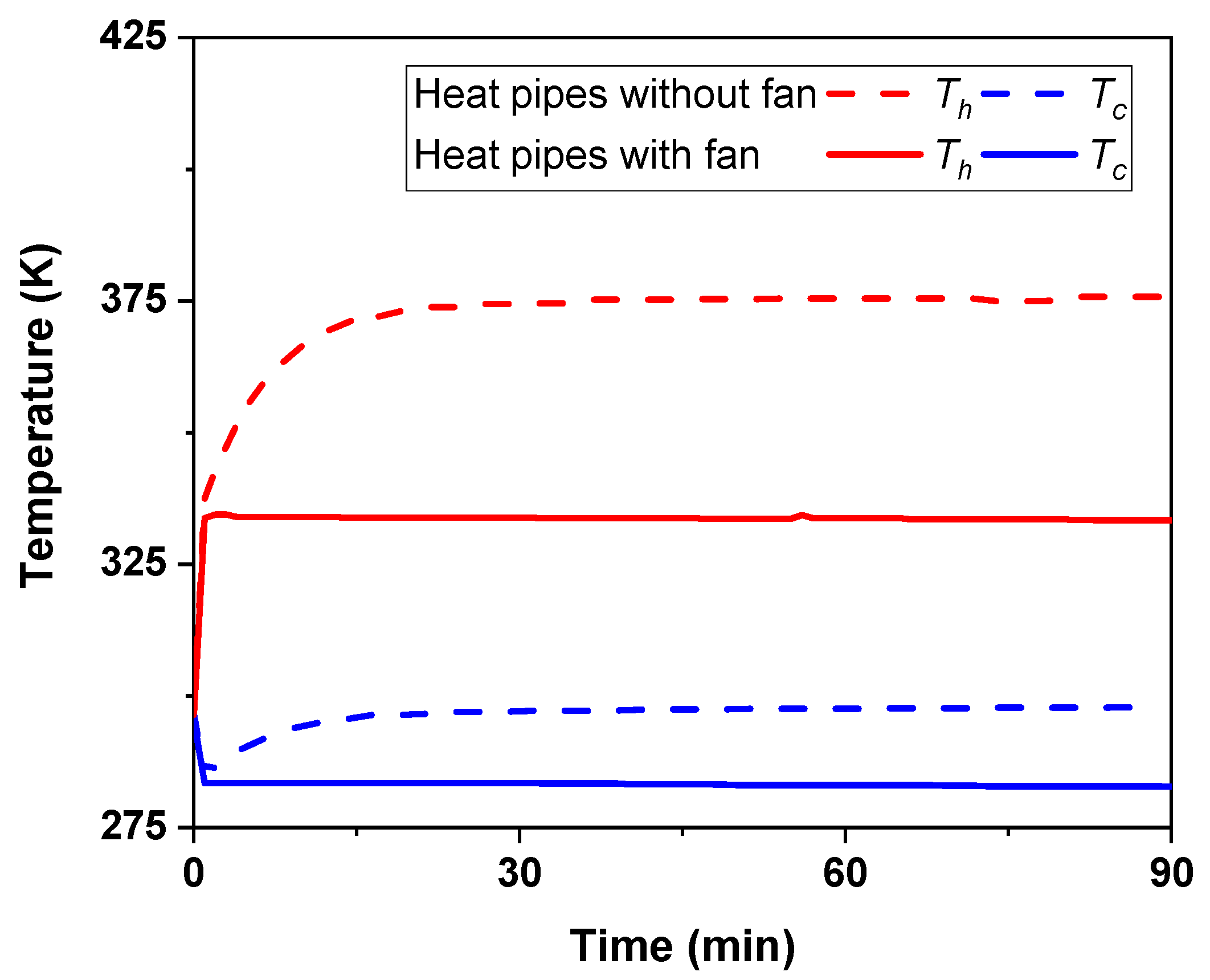
  • Removing the fan from the HPs negatively affected the TEM efficiency because of inadequate heat dissipation from the hot side.
  • This study shows that the COP increased from 0.25 to 0.53 as the ΔT decreased from 50.6 K to 27.2 K because a smaller ΔT reduces the heat conduction between the TEM sides, leading to a higher q c and COP.
  • The overall efficiency of the TEM was primarily controlled by the thermal resistance of both sides. According to the thermal resistance analysis, the COP of the TEM increases with a reduction in the thermal resistance on the hot and cold sides, which show minimum values of 0.17 and 0.63 K/W, respectively, for the optimized configuration.
To validate the real-world applicability of this optimized setup, a compact 12 L prototype refrigerator was constructed, incorporating HP assemblies and fans on both sides of the TEM. When tested indoors, the refrigerator achieved a cold-side temperature of 268.7 K, cooling the interior to 281.6 K within 30 min at a cooling rate of 20.73 W and a COP of 0.40. Outdoor testing further confirmed the design’s robustness under varying ambient conditions, with COP values consistently around 0.45 and cold-side temperatures ranging from 271.0 K to 278.4 K. The integration of HPs and TEMs presents a promising path toward more efficient small-scale cooling solutions. Future work will focus on enhancing the performance of TEM-based coolers further by optimizing the HPs’ condenser and the fan system. These advancements hold significant promise for expanding the practical applications of TEM-based cooling systems, particularly in sustainable, small-scale refrigeration for medical transport, portable food storage, and off-grid cooling solutions in remote or resource-limited environments.

Funding

This research received no external funding.

Data Availability Statement

The data presented in this study are available on request from the author.

Acknowledgments

I appreciate the sabbatical leave support from Yanbu Industrial College, the Royal Commission for Jubail and Yanbu, Kingdom of Saudi Arabia. During the preparation of this manuscript/study, the author used ChatGPT 4.0 and Paperpal (Version 4.2.2) for the purposes of editing and rewriting some texts in the manuscript to enhance its readability. The author has reviewed and edited the output and takes full responsibility for the content of this publication.

Conflicts of Interest

The author declares no conflicts of interest.

Abbreviations

The following abbreviations are used in this manuscript:
AGHPsAxially grooved heat pipes [-];
AlAluminum [-];
A b Unfinned surface area of the HPs condenser [m2];
A f Fin surface area [m2];
COPCoefficient of performance [-];
DCDirect current [-];
ΔTTemperature difference between the TEM sides [K];
h Convective heat transfer coefficient [W/m2K];
HPsHeat pipes [-];
ICurrent [A];
ItotTotal electrical current supplied to the cooler system [A];
KThermal conductance [W/K];
N Number of fins [-];
PVCPolyvinyl chloride [-];
PApplied electrical power to the TEM cooling system [W];
P T E M Electric power supplied to the TEM [W];
q c Heat transfer rate into the cold side [W];
q h Heat transfer rate out of the hot side [W];
RElectrical resistance [Ω];
R b Convective resistance from the unfinned surfaces of the HPs condenser [K/W];
R c , c Thermal contact resistance on the cold side [K/W];
R c , h Thermal contact resistance on the hot side [K/W];
R H P s Thermal resistance of the HPs [K/W];
R f i n Thermal resistance of the fin array [K/W];
R T E M Conduction thermal resistance of the TEM [K/W];
R t o t , h Hot-side thermal resistance [K/W];
R t o t , c Cold-side thermal resistance [K/W];
SSeebeck coefficient [V/K];
TEMThermoelectric module [-];
T c Cold-side temperature [K];
T Ambient air temperature [K];
T h Hot-side temperature [K];
VVoltage [V];
Greek symbols
η f Fin efficiency [-].

References

  1. Mao, J.; Chen, G.; Ren, Z. Thermoelectric Cooling Materials. Nat. Mater. 2021, 20, 454–461. [Google Scholar] [CrossRef] [PubMed]
  2. Bell, L.E. Cooling, Heating, Generating Power, and Recovering Waste Heat with Thermoelectric Systems. Science 2008, 321, 1457–1461. [Google Scholar] [CrossRef] [PubMed]
  3. Min, G.; Rowe, D.M. Experimental Evaluation of Prototype Thermoelectric Domestic-Refrigerators. Appl. Energy 2006, 83, 133–152. [Google Scholar] [CrossRef]
  4. Tassou, S.A.; Lewis, J.S.; Ge, Y.T.; Hadawey, A.; Chaer, I. A Review of Emerging Technologies for Food Refrigeration Applications. Appl. Therm. Eng. 2010, 30, 263–276. [Google Scholar] [CrossRef]
  5. Hu, B.; Shi, X.L.; Zou, J.; Chen, Z.G. Thermoelectrics for Medical Applications: Progress, Challenges, and Perspectives. Chem. Eng. J. 2022, 437, 135268. [Google Scholar] [CrossRef]
  6. Hermes, C.J.L.; Barbosa, J.R. Thermodynamic Comparison of Peltier, Stirling, and Vapor Compression Portable Coolers. Appl. Energy 2012, 91, 51–58. [Google Scholar] [CrossRef]
  7. Güler, N.F.; Ahiska, R. Design and Testing of a Microprocessor-Controlled Portable Thermoelectric Medical Cooling Kit. Appl. Therm. Eng. 2002, 22, 1271–1276. [Google Scholar] [CrossRef]
  8. Cai, Y.; Wang, Y.; Liu, D.; Zhao, F.Y. Thermoelectric Cooling Technology Applied in the Field of Electronic Devices: Updated Review on the Parametric Investigations and Model Developments. Appl. Therm. Eng. 2019, 148, 238–255. [Google Scholar] [CrossRef]
  9. Enescu, D.; Virjoghe, E.O. A Review on Thermoelectric Cooling Parameters and Performance. Renew. Sustain. Energy Rev. 2014, 38, 903–916. [Google Scholar] [CrossRef]
  10. Astrain, D.; Aranguren, P.; Martínez, A.; Rodríguez, A.; Pérez, M.G. A Comparative Study of Different Heat Exchange Systems in a Thermoelectric Refrigerator and Their Influence on the Efficiency. Appl. Therm. Eng. 2016, 103, 1289–1298. [Google Scholar] [CrossRef]
  11. Riffat, S.B.; Ma, X. Improving the Coefficient of Performance of Thermoelectric Cooling Systems: A Review. Int. J. Energy Res. 2004, 28, 753–768. [Google Scholar] [CrossRef]
  12. Liu, Z.; Hu, G.; Wang, J.; Suo, Y.; Ye, Y.; Li, G.; Zhang, Z. Design and Optimization of a Cubic Two-Stage Thermoelectric Cooler for Thermal Performance Enhancement. Energy Convers. Manag. 2022, 271, 116259. [Google Scholar] [CrossRef]
  13. Zhao, D.; Tan, G.; Yang, L.; Chen, Z.G.; Dargusch, M.S.; Zou, J.; Zhao, D.; Tan, G. A Review of Thermoelectric Cooling: Materials, Modeling and Applications. Appl. Therm. Eng. 2014, 66, 15–24. [Google Scholar] [CrossRef]
  14. Hu, Y.; Shen, B. Experimental Insights into Thermoelectric Freezer Systems: Feasibility and Efficiency. Energy Convers. Manag. X 2024, 23, 100676. [Google Scholar] [CrossRef]
  15. Dai, Y.J.; Wang, R.Z.; Ni, L. Experimental Investigation and Analysis on a Thermoelectric Refrigerator Driven by Solar Cells. Sol. Energy Mater. Sol. Cells 2003, 77, 377–391. [Google Scholar] [CrossRef]
  16. Abdul-Wahab, S.A.; Elkamel, A.; Al-Damkhi, A.M.; Al-Habsi, I.A.; Al-Rubai’ey’, H.S.; Al-Battashi, A.K.; Al-Tamimi, A.R.; Al-Mamari, K.H.; Chutani, M.U. Design and Experimental Investigation of Portable Solar Thermoelectric Refrigerator. Renew. Energy 2009, 34, 30–34. [Google Scholar] [CrossRef]
  17. Rahman, S.M.A.; Hachicha, A.A.; Ghenai, C.; Saidur, R.; Said, Z. Performance and Life Cycle Analysis of a Novel Portable Solar Thermoelectric Refrigerator. Case Stud. Therm. Eng. 2020, 19, 100599. [Google Scholar] [CrossRef]
  18. Afshari, F.; Akif Ceviz, M.; Mandev, E.; Yıldız, F. Effect of Heat Exchanger Base Thickness and Cooling Fan on Cooling Performance of Air-To-Air Thermoelectric Refrigerator; Experimental and Numerical Study. Sustain. Energy Technol. Assess. 2022, 52, 102178. [Google Scholar] [CrossRef]
  19. Çağlar, A. Optimization of Operational Conditions for a Thermoelectric Refrigerator and Its Performance Analysis at Optimum Conditions. Int. J. Refrig. 2018, 96, 70–77. [Google Scholar] [CrossRef]
  20. He, Y.; Cao, C.; Wu, J.; Chen, G. Investigations on Coupling between Performance and External Operational Conditions for a Semiconductor Refrigeration System. Int. J. Refrig. 2020, 109, 172–179. [Google Scholar] [CrossRef]
  21. Gökçek, M.; Şahin, F. Experimental Performance Investigation of Minichannel Water Cooled-Thermoelectric Refrigerator. Case Stud. Therm. Eng. 2017, 10, 54–62. [Google Scholar] [CrossRef]
  22. Abderezzak, B.; Dreepaul, R.K.; Busawon, K.; Chabane, D. Experimental Characterization of a Novel Configuration of Thermoelectric Refrigerator with Integrated Finned Heat Pipes. Int. J. Refrig. 2021, 131, 157–167. [Google Scholar] [CrossRef]
  23. Ohara, B.; Sitar, R.; Soares, J.; Novisoff, P.; Nunez-Perez, A.; Lee, H. Optimization Strategies for a Portable Thermoelectric Vaccine Refrigeration System in Developing Communities. J. Electron. Mater. 2015, 44, 1614–1626. [Google Scholar] [CrossRef]
  24. Vián, J.G.G.; Astrain, D. Development of a Thermoelectric Refrigerator with Two-Phase Thermosyphons and Capillary Lift. Appl. Therm. Eng. 2009, 29, 1935–1940. [Google Scholar] [CrossRef]
  25. Faghri, A. Review and Advances in Heat Pipe Science and Technology. J. Heat Transfer 2012, 134. [Google Scholar] [CrossRef]
  26. Ku, J. Introduction to Heat Pipes. In Proceedings of the Thermal Fluids and Analysis Workshop (TFAWS) 2015, Silver Spring, MD, USA, 3–7 August 2015; p. 74. [Google Scholar]
  27. Riffat, S.B.; Omer, S.A.; Ma, X. A Novel Thermoelectric Refrigeration System Employing Heat Pipes and a Phase Change Material: An Experimental Investigation. Renew. Energy 2001, 23, 313–323. [Google Scholar] [CrossRef]
  28. Liang, K.; Li, Z.; Chen, M.; Jiang, H. Comparisons between Heat Pipe, Thermoelectric System, and Vapour Compression Refrigeration System for Electronics Cooling. Appl. Therm. Eng. 2019, 146, 260–267. [Google Scholar] [CrossRef]
  29. Liu, Y.; Su, Y. Experimental Investigations on COPs of Thermoelectric Module Frosting Systems with Various Hot Side Cooling Methods. Appl. Therm. Eng. 2018, 144, 747–756. [Google Scholar] [CrossRef]
  30. Siddique, A.R.M.; Bozorgi, M.; Venkateshwar, K.; Tasnim, S.; Mahmud, S. Phase Change Material-Enhanced Solid-State Thermoelectric Cooling Technology for Food Refrigeration and Storage Applications. J. Energy Storage 2023, 60, 106569. [Google Scholar] [CrossRef]
  31. Fenton, E.; Bozorgi, M.; Tasnim, S.; Mahmud, S. Solar-Powered Thermoelectric Refrigeration with Integrated Phase Change Material: An Experimental Approach to Food Storage. J. Energy Storage 2024, 79, 110247. [Google Scholar] [CrossRef]
  32. Kaiprath, J.; Kishor Kumar, V.V. A Review on Solar Photovoltaic-Powered Thermoelectric Coolers, Performance Enhancements, and Recent Advances. Int. J. Air Cond. Refrig. 2023, 31, 6. [Google Scholar] [CrossRef]
  33. Alrefae, M.A. Influence of Heat Dissipation on the Performance of a Thermoelectric Module. In Proceedings of the International Heat Transfer Conference 17, Cape Town, South Africa, 14–18 August 2023; Begell House Inc.: Danbury, CT, USA, 2023; p. ID: 575. [Google Scholar]
  34. Cai, Y.; Liu, D.; Zhao, F.Y.; Tang, J.F. Performance Analysis and Assessment of Thermoelectric Micro Cooler for Electronic Devices. Energy Convers. Manag. 2016, 124, 203–211. [Google Scholar] [CrossRef]
  35. Bergman, T.L.; Lavine, A.S.; Incropera, F.P.; Dewitt, D.P. Fundamentals of Heat and Mass Transfer, 7th ed.; Wiley: Hoboken, NJ, USA, 2011. [Google Scholar]
  36. Zeghari, K.; Louahlia, H. Flat Miniature Heat Pipe with Sintered Porous Wick Structure: Experimental and Mathematical Studies. Int. J. Heat Mass Transf. 2020, 158, 120021. [Google Scholar] [CrossRef]
  37. Poplaski, L.M.; Faghri, A.; Bergman, T.L. Analysis of Internal and External Thermal Resistances of Heat Pipes Including Fins Using a Three-Dimensional Numerical Simulation. Int. J. Heat Mass Transf. 2016, 102, 455–469. [Google Scholar] [CrossRef]
  38. Sun, X.; Zhang, L.; Liao, S. Performance of a Thermoelectric Cooling System Integrated with a Gravity-Assisted Heat Pipe for Cooling Electronics. Appl. Therm. Eng. 2017, 116, 433–444. [Google Scholar] [CrossRef]
  39. Sun, X.; Ling, L.; Liao, S.; Chu, Y.; Fan, S.; Mo, Y. A Thermoelectric Cooler Coupled with a Gravity-Assisted Heat Pipe: An Analysis from Heat Pipe Perspective. Energy Convers. Manag. 2018, 155, 230–242. [Google Scholar] [CrossRef]
  40. Aranguren, P.; DiazDeGarayo, S.; Martínez, A.; Araiz, M.; Astrain, D. Heat Pipes Thermal Performance for a Reversible Thermoelectric Cooler-Heat Pump for a NZEB. Energy Build. 2019, 187, 163–172. [Google Scholar] [CrossRef]
  41. Park, S.J.; Bang, K.M.; Kim, B.; Ziolkowski, P.; Jeong, J.R.; Jin, H. Adaptive Thermoelectric Cooling System for Energy-Efficient Local and Transient Heat Management. Appl. Therm. Eng. 2022, 216, 119060. [Google Scholar] [CrossRef]
  42. Russel, M.K.; Ewing, D.; Ching, C.Y. Characterization of a Thermoelectric Cooler Based Thermal Management System under Different Operating Conditions. Appl. Therm. Eng. 2013, 50, 652–659. [Google Scholar] [CrossRef]
  43. Phelan, P.E.; Chiriac, V.A.; Tom Lee, T.Y. Current and Future Miniature Refrigeration Cooling Technologies for High Power Microelectronics. IEEE Trans. Compon. Packag. Technol. 2002, 25, 356–365. [Google Scholar] [CrossRef]
  44. Chang, Y.W.; Chang, C.C.; Ke, M.T.; Chen, S.L. Thermoelectric Air-Cooling Module for Electronic Devices. Appl. Therm. Eng. 2009, 29, 2731–2737. [Google Scholar] [CrossRef]
  45. Zhang, H.Y.; Mui, Y.C.; Tarin, M. Analysis of Thermoelectric Cooler Performance for High Power Electronic Packages. Appl. Therm. Eng. 2010, 30, 561–568. [Google Scholar] [CrossRef]
  46. Choi, J.; Jeong, M.; Yoo, J.; Seo, M. A New CPU Cooler Design Based on an Active Cooling Heatsink Combined with Heat Pipes. Appl. Therm. Eng. 2012, 44, 50–56. [Google Scholar] [CrossRef]
Figure 1. (a) Schematic of the experimental setup of the thermoelectric module (TEM) connected to the heat pipes (HPs). (b) Image of the TEM-based cooler. The inset in (b) shows an image of the TEM connected to the HPs with the fan.
Energies 18 02426 g001
Figure 2. Thermal resistance network of the TEM with HPs on both sides.
Energies 18 02426 g002
Figure 3. The hot- and cold-side temperatures of the TEM with HPs on the hot side and a cooling plate on the cold side.
Energies 18 02426 g003
Figure 4. Effects of HP cooling fan on hot- and cold-side temperatures. The cold side was connected to a cooling plate in both cases.
Energies 18 02426 g004
Figure 5. Hot- and cold-side temperatures for TEM with HPs on both sides and the hot side only.
Energies 18 02426 g005
Figure 6. Air temperature near the hot-side HPs, ambient air temperature, and temperature inside the refrigerator utilizing TEM with HPs connected to both sides.
Energies 18 02426 g006
Figure 7. Refrigerator performance when placed outdoors with continuous (performed on 25 January 2025) or cyclic operations (18 January 2025): (a) TEM sides and air temperatures; (b) TEM sides and air temperatures differences.
Energies 18 02426 g007
Figure 8. Air temperature near the hot-side HPs, ambient air temperature, and temperature inside the refrigerator when placed outdoors with continuous (performed on 25 January 2025) or cyclic operations (18 January 2025).
Energies 18 02426 g008
Table 1. Temperatures, heat transfer rates, and thermal resistances of TEM sides with various boundary conditions in this study.
Configuration T h (K) T c (K)ΔT (K) q h (W) q c (W)COP R t o t , h (K/W) R t o t , c (K/W)
Hot side: HPs without fan
Cold side: heat exchange (or cooling plate)
376.7 ± 2.6298.1 ± 2.678.6 ± 5.218.69 ±0.44−6.78 ± 0.49-4.32 ± 0.100.33 ± 0.03
Hot side: HPs with fan
Cold side: heat exchange (or cooling plate)
333.1 ± 0.4282.4 ± 0.350.6 ± 0.742.48 ± 0.0911.10 ± 0.130.25 ± 0.010.87 ± 0.011.22 ± 0.03
Hot side: HPs with fan
Cold side: HPs with fan
305.6 ± 1.3278.5 ± 0.327.2 ± 1.661.94 ± 0.3226.26 ± 0.540.53 ± 0.010.17 ± 0.020.63 ± 0.03
Disclaimer/Publisher’s Note: The statements, opinions and data contained in all publications are solely those of the individual author(s) and contributor(s) and not of MDPI and/or the editor(s). MDPI and/or the editor(s) disclaim responsibility for any injury to people or property resulting from any ideas, methods, instructions or products referred to in the content.

