Article

Enhanced Three-Phase Shunt Active Power Filter Utilizing an Adaptive Frequency Proportional-Integral–Resonant Controller and a Sensorless Voltage Method

by
Haneen Ghanayem
1,*,
Mohammad Alathamneh
1,
Xingyu Yang
2,
Sangwon Seo
2 and
R. M. Nelms
2
1
Electrical Engineering Department, Al-Balqa Applied University, Salt 19117, Jordan
2
Electrical and Computer Engineering Department, Auburn University, Auburn, AL 36849, USA
*
Author to whom correspondence should be addressed.
Energies 2025, 18(1), 116; https://doi.org/10.3390/en18010116
Submission received: 4 December 2024 / Revised: 22 December 2024 / Accepted: 27 December 2024 / Published: 30 December 2024
(This article belongs to the Special Issue Power Electronics and Power Quality 2024)

Abstract

:
This article introduces a frequency-adaptive control strategy for a three-phase shunt active power filter, aimed at improving energy efficiency and ensuring high power quality in consumer-oriented power systems. The proposed control system utilizes real-time frequency estimation to dynamically adjust the gain of a proportional-integral–resonant (PIR) controller, facilitating precise harmonic compensation under challenging unbalanced grid conditions, such as unbalanced three-phase loads, grid impedance variations, and diverse nonlinear loads like three-phase rectifiers and induction motors. These scenarios often increase total harmonic distortion (THD) at the point of common coupling (PCC), degrading the performance of connected loads and reducing the efficiency of induction motors. The PIR controller integrates both proportional-integral (PI) and proportional-resonant (PR) control features, achieving improved stability and reduced overshoot. A novel voltage sensorless control method is proposed, requiring only current measurements to determine reference currents for the inverter, thereby simplifying the implementation. Validation of the frequency adaptive control scheme through MATLAB/Simulink simulations and real-time experiments on a dSPACE (DS1202) platform demonstrates significant improvements in harmonic compensation, energy efficiency, and system stability across varying grid frequencies. This approach offers a robust consumer-oriented solution for managing power quality, positioning the SAPF as a key technology for advancing sustainable energy management in smart applications.

1. Introduction

With the growing demand for energy, maintaining high power quality has become crucial to ensure the reliable and disturbance-free operation of consumer applications within modern power systems. Harmonic distortion, largely introduced by nonlinear loads such as rectifiers, generates harmonic currents that disrupt the ideal sinusoidal waveforms of voltage and current, diminishing the overall power quality and efficiency. The three-phase shunt active power filter (SAPF) is a vital technology in electrical power systems, designed to mitigate these harmonic distortions, thus improving power quality across the network. By reducing the adverse effects of harmonic distortion on connected electrical devices, the SAPF enhances system stability and efficiency, contributing to a more sustainable and energy-efficient infrastructure. This capability aligns directly with the goals of emerging consumer energy management technologies, which seek to improve energy efficiency, integrate seamlessly with smart home systems, and promote environmental sustainability [1].
A review of active filters for power quality improvement is presented in [2], highlighting strategies that play a critical role in enhancing the performance and stability of active power filters (APFs). A hybrid active power filter strategy was discussed in [3,4]. The basic concept of the instantaneous p-q theory is introduced in [5], while Ref. [6] proposes an active power filter utilizing an instantaneous reactive power control algorithm. This approach offers a simple modification that can be easily implemented into existing APFs, enhancing the effectiveness of harmonic compensation. Reference signals can be determined by analyzing the signal spectrum or individual harmonics using the discrete Fourier transform (DFT). Furthermore, several low-complexity mathematical algorithms, commonly referred to as sliding transformations, have been developed to enhance discrete-time signal processing. Improvements in the sliding discrete Fourier transform algorithm are proposed in [7]. In addition, a three-phase active power filter based on the sliding DFT control algorithm is presented in [8].
The performance of an SAPF is greatly influenced by the reference current control technique used and the current controller responsible for generating the switching signals for the voltage-sourced inverter (VSI). Reference current control is classified into time and frequency domains. Frequency-domain methods are complex, involving numerous calculations, high memory usage, and delays in harmonic extraction, which can degrade performance during transient conditions. In contrast, time-domain methods are simpler and more efficient, with the instantaneous reactive power theory (IRPT) and the synchronous reference frame (SRF) system being the most widely adopted approaches [9].
In the last decade, a growing focus on sensorless grid–voltage control was studied [10]. This approach aims to lower system costs, improve the reliability, and vanquish problems related to physical sensors, such as offsets, noise, and the risk of failure. A modified adaptive Kalman filter for sensorless current control in a three-phase inverter-based distributed generation system is proposed in [11], while a simplified voltage-sensorless active damping scheme for three-phase PWM converters with an LCL filter is proposed in [12]. The time-domain symmetrical component extraction method (SCEM) utilizes straightforward arithmetic operations to compute sequence components, offering a computationally efficient alternative to transformation-based methods, as discussed in [13,14].
The fluctuation in the real and reactive power of the grid can have a negative impact on the performance of the inverter operation and the other three-phase loads connected to the grid.
Various control strategies have been developed to facilitate efficient bidirectional power management for grid-connected inverters under these conditions. The power control of a three-phase grid-connected inverter using proportional-integral (PI) control under unbalanced conditions is proposed in [15], while the proportional-resonant control for bidirectional power control of a three-phase grid-connected inverter under unbalanced grid conditions is proposed in [16].
Several adaptive control schemes have been proposed, including the use of adaptive notch filtering [17,18]. An adaptive control strategy was proposed and evaluated with the least mean square (LMS) and least mean fourth (LMF) algorithms [19]. The performance of a PI controller-based variable step-size LMS control algorithm was analyzed in [20], while Ref. [21] proposed a variable step-size-based adaptive LMS algorithm using an optimizing PI control method. One of the key challenges in implementing frequency adaptive control schemes is maintaining precise frequency estimation, as inaccuracies in the estimated frequency can result in errors in the compensating current. To enhance the frequency estimation accuracy, advanced estimation methods, for example, the Kalman filter and extended Kalman filter, have been proposed [22,23].
Recent advancements in PR control have expanded its applicability in broadband impedance matching and adaptive control systems, particularly in addressing frequency-dependent challenges. For instance, the development of self-adaptive PR controllers has demonstrated enhanced transient response and real-time tunability, which are critical for wideband applications such as acoustic and electromagnetic resonance systems [24]. Furthermore, hybrid impedance matching approaches, combining active and passive techniques, have shown improved dynamic performance and broader frequency ranges in reactive load compensation, highlighting the effectiveness of PR-based control in advanced power electronic applications [25]. These contributions underscore the potential of PR control methodologies to overcome bandwidth and frequency adaptability limitations, forming a strong motivation for the frequency adaptive enhancements proposed in this study.
Fixed-frequency operation is considered as one of the limitations of existing methods. Thus, this paper presents an innovative frequency-adaptive control approach for the SAPF, with the main objective of improving the steady-state performance and the accuracy. The approach incorporates a frequency detection approach along with the PIR controller to achieve enhanced performance. The proposed control system was evaluated through simulations and experiments setup, validating its effectiveness and feasibility.
This paper introduces an enhanced performance controller—the PIR controller—which combines the advantages of both PI and PR controllers to improve energy efficiency and stability in consumer-oriented power systems. Addressing complex load scenarios such as unbalanced grid conditions (including three-phase load and impedance imbalances) and diverse nonlinear loads, like three-phase rectifiers and induction motors, the proposed method minimizes THD in PCC voltages and grid currents. Such distortions can adversely affect connected devices, reducing the performance and efficiency, particularly in consumer electronics applications like induction motors. The proposed adaptive approach not only balances and reduces the harmonic content across the power system but also enhances the system stability and responsiveness, with the PIR controller offering lower overshoot and steady-state error compared to conventional PR controllers. This improvement is especially valuable for dynamic consumer-focused applications that require robust high-quality power management aligned with sustainable energy goals.

2. Grid-Connected Inverter and PIR Control Approach

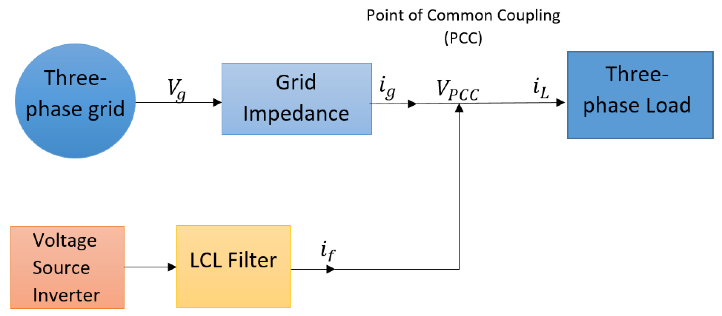
2.1. Design and Configuration of Shunt Active Power Filter

Figure 1 depicts the three-phase three-wire system being analyzed, which includes key elements such as the Thevenin’s equivalent circuit of the grid, which is a three-phase AC voltage source in series with a grid impedance ( Z g ), a load, and an SAPF connected at the point-of-common coupling (PCC). The SAPF setup consists of a three-phase inverter, an LCL filter, and a DC power source. In this system, ( V g ) represents the grid voltage, ( V P C C ) corresponds to the PCC voltage, ( i g ) denotes the grid currents, ( i L ) refers to the load currents, and ( i f ) indicates the filter currents. Notably, the suggested control approach depends solely on the current measurements of ( i L ) and ( i g ), removing the requirement for voltage measurements or estimations.
As delineated in [14], an unbalanced load can cause unbalanced grid currents and PCC voltages. The unbalanced ( i L ) can be broken down into three components: fundamental ( i 1 ), harmonic ( i h ), and reactive ( i q ), as explained in (1).
In the research outlined in [14], the application of SAPF successfully corrected and stabilized the grid currents by counteracting the unwanted components of the unbalanced load currents, as depicted in (2). Consequently, these undesirable components were mitigated.
i L = i 1 + i h + i q
i f = ( i h + i q )

2.2. Symmetrical Components Extraction Method

To compute the positive and negative sequence components of a three-phase system, the symmetrical components extraction method (SCEM) was applied in the time domain. In its conventional form, SCEM utilizes the operator a ¯ , which is defined as 1 120 = 1 240 . This operator corresponds to a time delay of 1 / 90 seconds for a 60 Hz system. Similarly, a ¯ 2 is defined as 1 240 = 1 120 , representing a time delay of 1 / 180 s for the same frequency. The symmetrical components in the time domain can be derived using Equations (3) and (4) with the operator a ¯ or through Equations (5) and (6).
f ( 1 ) ( t ) = 1 3 ( f a ( t ) + α ¯ f b ( t ) + α ¯ 2 f c ( t ) )
f ( 2 ) ( t ) = 1 3 ( f a ( t ) + α ¯ 2 f b ( t ) + α ¯ f c ( t ) )
f ( 1 ) ( t ) = 1 3 ( f a ( t ) + f b ( t 1 90 ) + f c ( t 1 180 ) )
f ( 2 ) ( t ) = 1 3 ( f a ( t ) + f b ( t 1 180 ) + f c ( t 1 90 ) )
Previous studies [11,12] proposed a voltage sensorless approach to segregate unbalanced load currents into their symmetrical components: positive sequence ( i L ( 1 ) ), negative sequence ( i L ( 2 ) ), and zero sequence ( i L ( 0 ) ). In systems without grounding, the zero-sequence component ( i L ( 0 ) ) was assumed to be negligible, as defined in (7). The positive and negative sequence components were extracted using the SCEM. The undesirable negative sequence component ( i L ( 2 ) ) was then injected into the system via the filter, as shown in Figure 2 and formulated in (8).
i L = i L ( 1 ) + i L ( 2 )
i f = i L ( 2 )

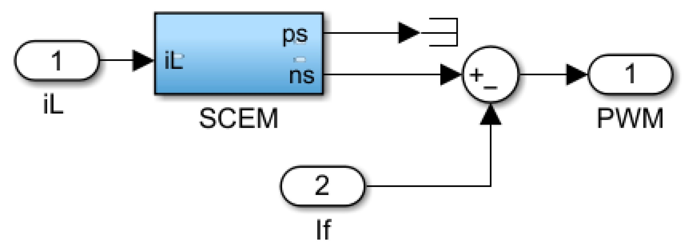
3. SAPF Method Using Only Current Measurements

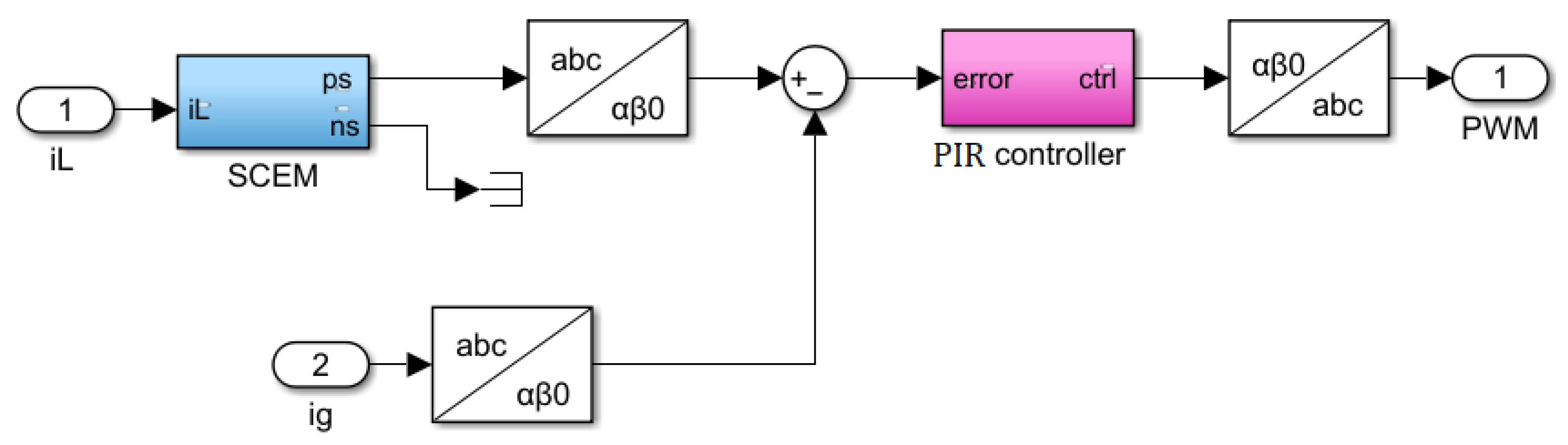
3.1. SAPF Employing the PIR Controller

A sensorless voltage control strategy is proposed in [16] to regulate grid currents in the presence of unbalanced three-phase load conditions. This approach leverages i L and i g to align i g with the balanced portion of the load, represented by the i L ( 1 ) , as defined in (9). In contrast to the method presented in [11], which relies on feedback from the ( i f ), this approach uses grid current feedback. Through the Clarke transformation [22], both the reference and feedback currents are converted from the a b c frame to the α β domain. The controller is then designed to reduce errors and achieve balanced grid currents, as described in (10).
i r e f = i L ( 1 )
i g = i L ( 1 )
A PIR controller is an advanced control technique that amalgamates proportional, integral, and resonant control elements to augment the overall performance of the SAPF. The transfer function of the PIR controller is delineated by (11). The PIR controller is implemented, as depicted in Figure 3 [26].
G P I R ( s ) = K p + K i s + K r s s 2 + ω 2
The control gains, ( K p ), ( K i ), and ( K r ), donate the proportional, integral, and resonant control coefficients, respectively, while ω represents the fundamental angular frequency.
The process of determining the appropriate gains for the PIR controller follows a structured approach:
  • The proportional gain ( K p ) is configured to a relatively low value to ensure system stability while minimizing overshoot in the operation of the SAPF.
  • The integral gain ( K i ) is carefully selected to remain minimal. While increasing K i can effectively reduce steady-state errors, it may also lead to undesirable effects such as overshoot and oscillations, thereby impacting system performance.
  • Achieving optimal control performance requires tuning the resonant gain ( K r ) and adjusting the angular frequency ( ω ) to align precisely with the grid frequency. However, excessive values of K r can compromise the system stability, necessitating careful calibration.
  • Ultimately, the selection of PIR controller gains demands a meticulous balance between achieving sufficient gain and preserving the overall system stability and reliability.

3.2. Challenges of SAPF Control Under Frequency Variation

In Section 2.2, the SCEM utilizes Equations (5) and (6), which are specifically tailored for systems operating at a fixed frequency of 60 Hz. Similarly, in the PIR controller design presented in Section 3.1, the angular frequency ω is defined based on the fundamental grid frequency, calculated as ω = 2 π f = 2 π ( 60 ) = 377 rad s .
However, variations in system load and generation can result in frequency fluctuations, introducing errors and inaccuracies in system calculations. Such fluctuations disrupt the SCEM process and adversely affect the performance of both PR and PIR controllers. As a result, the accurate determination of positive and negative symmetrical components cannot be guaranteed under frequency deviations. This limitation renders the approaches in references [11,12], which rely on SCEM, and the PR-based method in reference [16], including the proposed PIR controller, inadequate for handling systems subject to frequency variations.

4. The Proposed Method

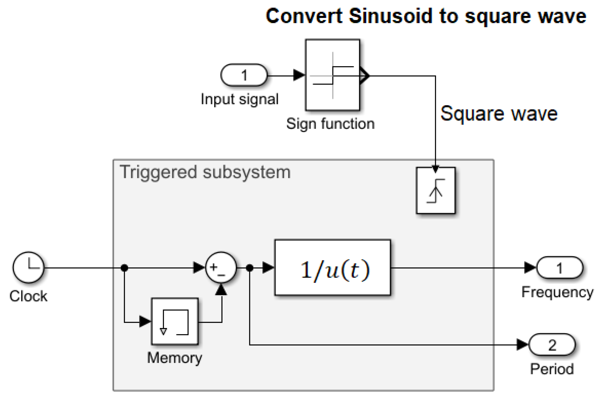
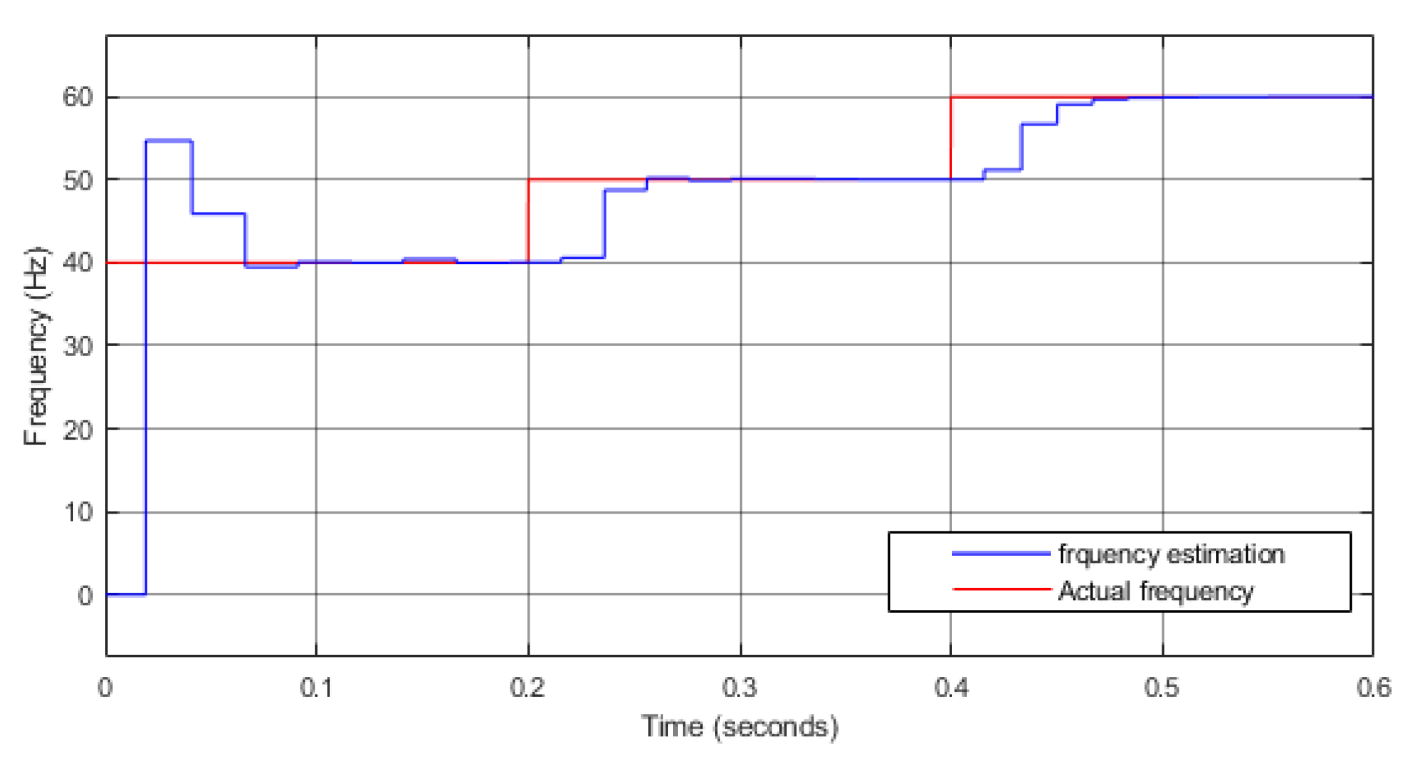
4.1. Frequency Estimation Technique

Figure 4 presents the proposed frequency detection method, which operates by transforming the sinusoidal signal into a square waveform. The frequency is determined by calculating the time interval between two successive rising edges of the square waveform as it crosses the zero axis.

4.2. Enhanced Symmetrical Components Extraction Method

Equations (5) and (6) in the symmetrical component extraction method (SCEM), as presented in Section 2.2, are specifically designed for a fixed frequency of 60 Hz, with associated time delays of 1 / 90 s and 1 / 180 s. However, variations in system load and generation can lead to deviations from this nominal frequency, introducing inaccuracies in the results derived from these equations. To address this issue, the time delay parameters can be recalibrated to 2 / 3 f s and 1 / 3 f s, where f represents the system’s actual frequency, thereby enabling the method to operate effectively across a range of frequencies. As a result, the SCEM is reformulated and modified, as shown in Equations (12) and (13). Nevertheless, the implementation of this enhanced SCEM (ESCEM) necessitates the integration of a frequency estimator, as detailed in Section 4.1, to ensure accurate frequency adaptation.
f ( 1 ) ( t ) = 1 3 ( f a ( t ) + f b ( t 2 3 f ) + f c ( t 1 3 f ) )
f ( 2 ) ( t ) = 1 3 ( f a ( t ) + f b ( t 1 3 f ) + f c ( t 2 3 f ) )

4.3. Frequency Adaptive Proportional-Integral-Resonant (PIR) Controller

In Section 3.1, the development of the PIR controller was based on the assumption of a fixed fundamental grid frequency of 60 Hz. However, due to fluctuations in system load and power generation, the grid frequency may deviate from this value. As a result, it becomes necessary to dynamically adjust the fundamental angular frequency ( ω ) within the PIR controller. This adjustment is achieved by employing the frequency estimation technique outlined in Section 4.1, which calculates the actual system frequency and updates the controller gain ( ω ) accordingly, using the relationship ω = 2 π f . This process enables the implementation of an adaptive PIR controller that remains effective across varying system frequencies, ensuring robust operation under frequency fluctuations.

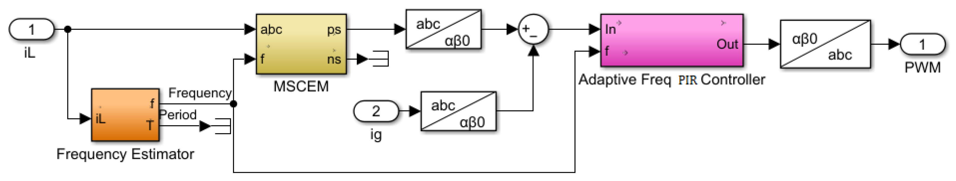
4.4. The Integrated Control Approach

The proposed SAPR control approach using an adaptive PIR controller, as outlined in Section 3.1 and illustrated in Figure 3, can be further refined through three significant enhancements:
  • Incorporating a frequency estimation mechanism,
  • Enhancing the SCEM to account for variations in frequency,
  • Using the estimated frequency, dynamically adjust the frequency parameter of the PIR controller.
These modifications collectively contribute to improving the adaptability and performance of the system under varying grid conditions. Figure 5 presents the block diagram of the frequency-adaptive PIR controller, tailored for the SAPF applications using only current measurments.

5. Case Studies

Several tests were performed under different operating frequencies of 58 Hz, 60 Hz, and 62 Hz for the system shown in Figure 6. The hardware setup includes an NHR 9410 grid simulator functioning as a programmable three-phase AC source, a three-phase DC-AC AgileSwitch 100 kW inverter, a dSPACE DS1202 real-time interface (RTI) platform, an NHR 9210 DC source, Matlab/Simulink, dSpace ControlDesk, oscilloscope, and measurement boards for monitoring voltage and current. The PIR controller was calibrated as outlined in Section 3.1, with the angular frequency calculated using the frequency estimator approach detailed in Section 4.1 and Section 4.3. The design parameters for the LCL filter were determined as per [27]. The system parameters are summarized in Table 1.
The NHR 9410 is called a regenerative grid simulator system. The load consisted of three different components: a three-phase resistive load bank manufactured by General Electric Company, Boston, Massachusetts, United States., a three-phase rectifier connected to a resistive load, and a three-phase induction motor manufactured by Pacer Motors Company, Bangalore, Karnataka, India.

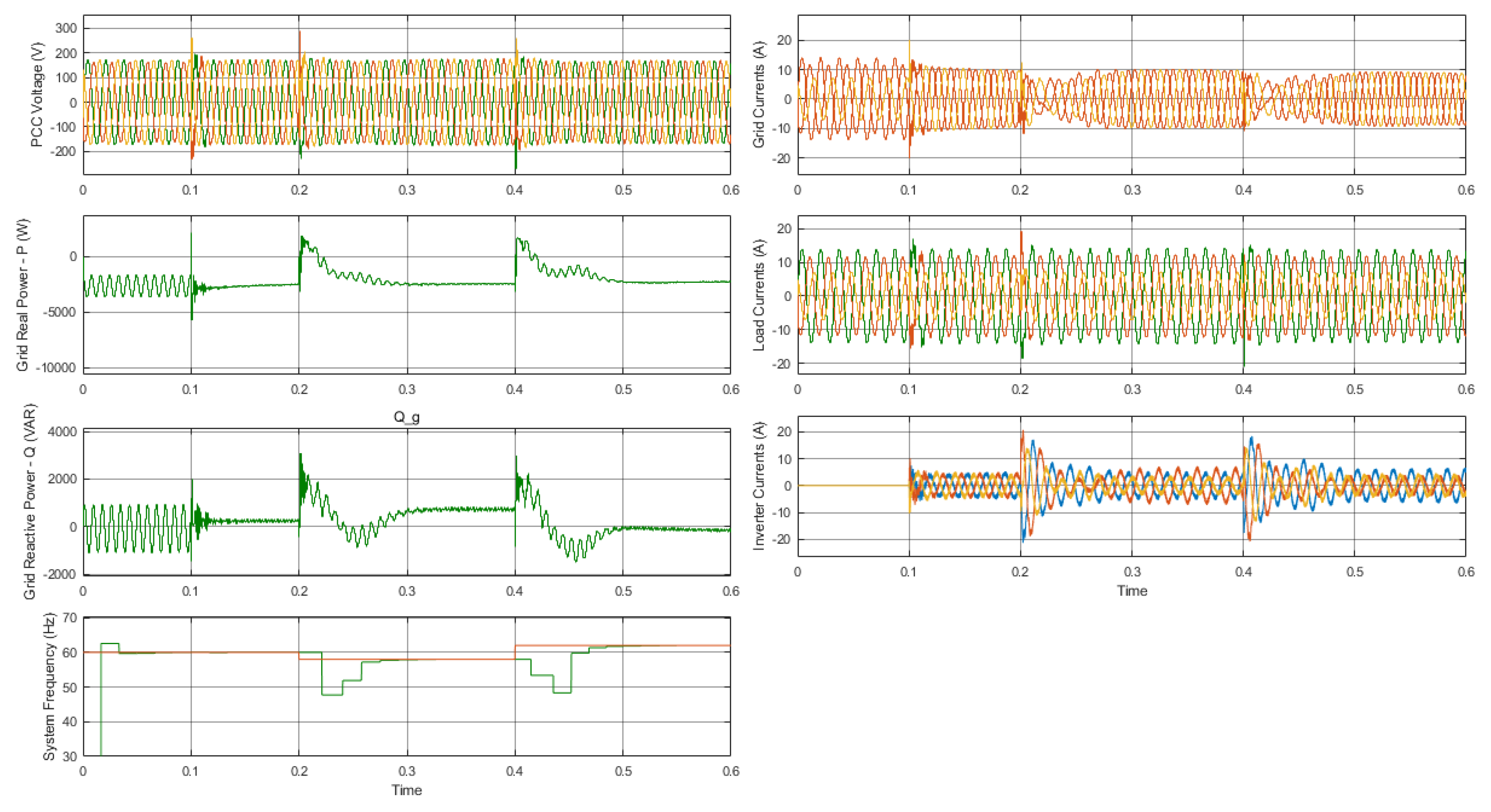
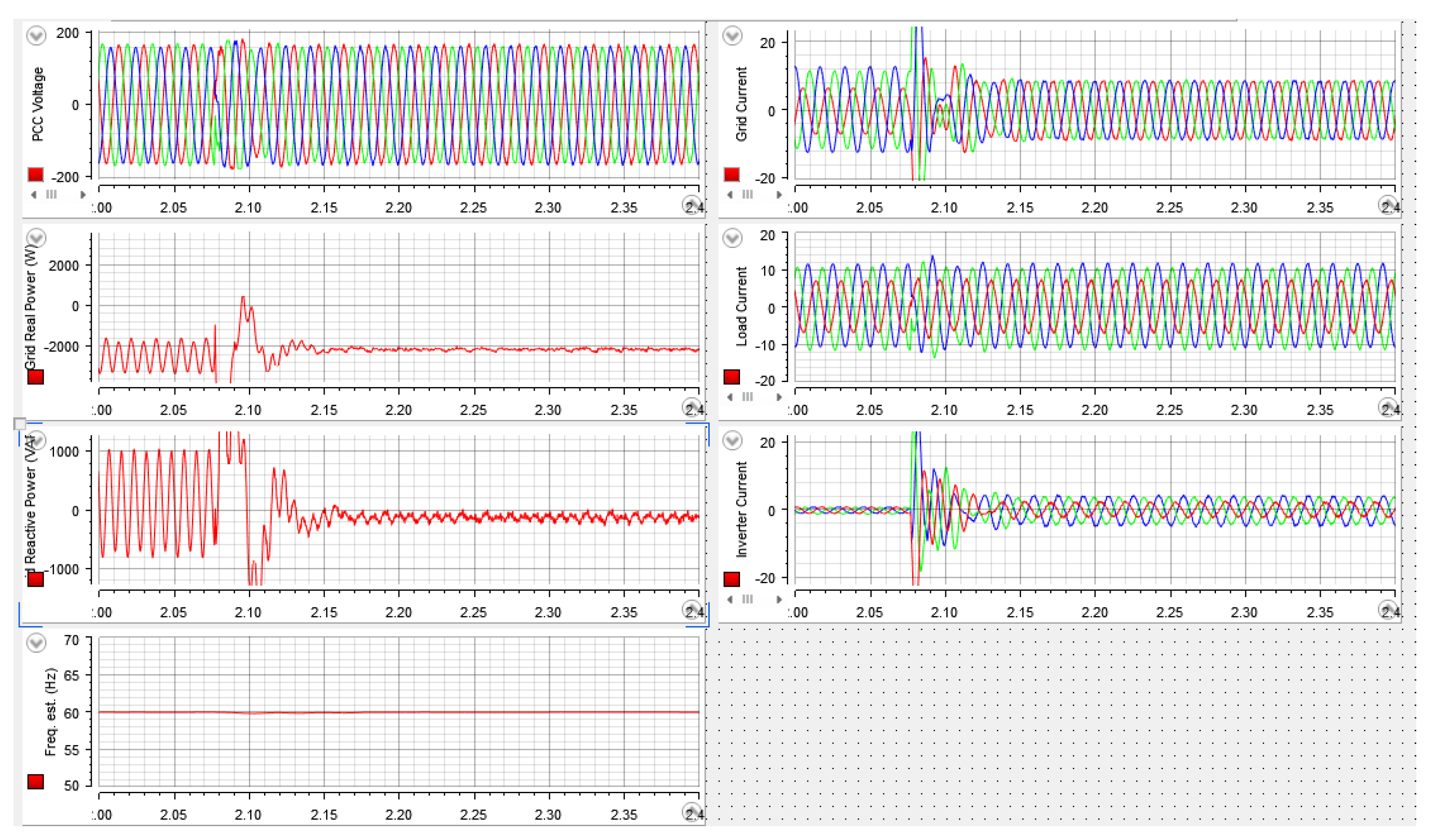
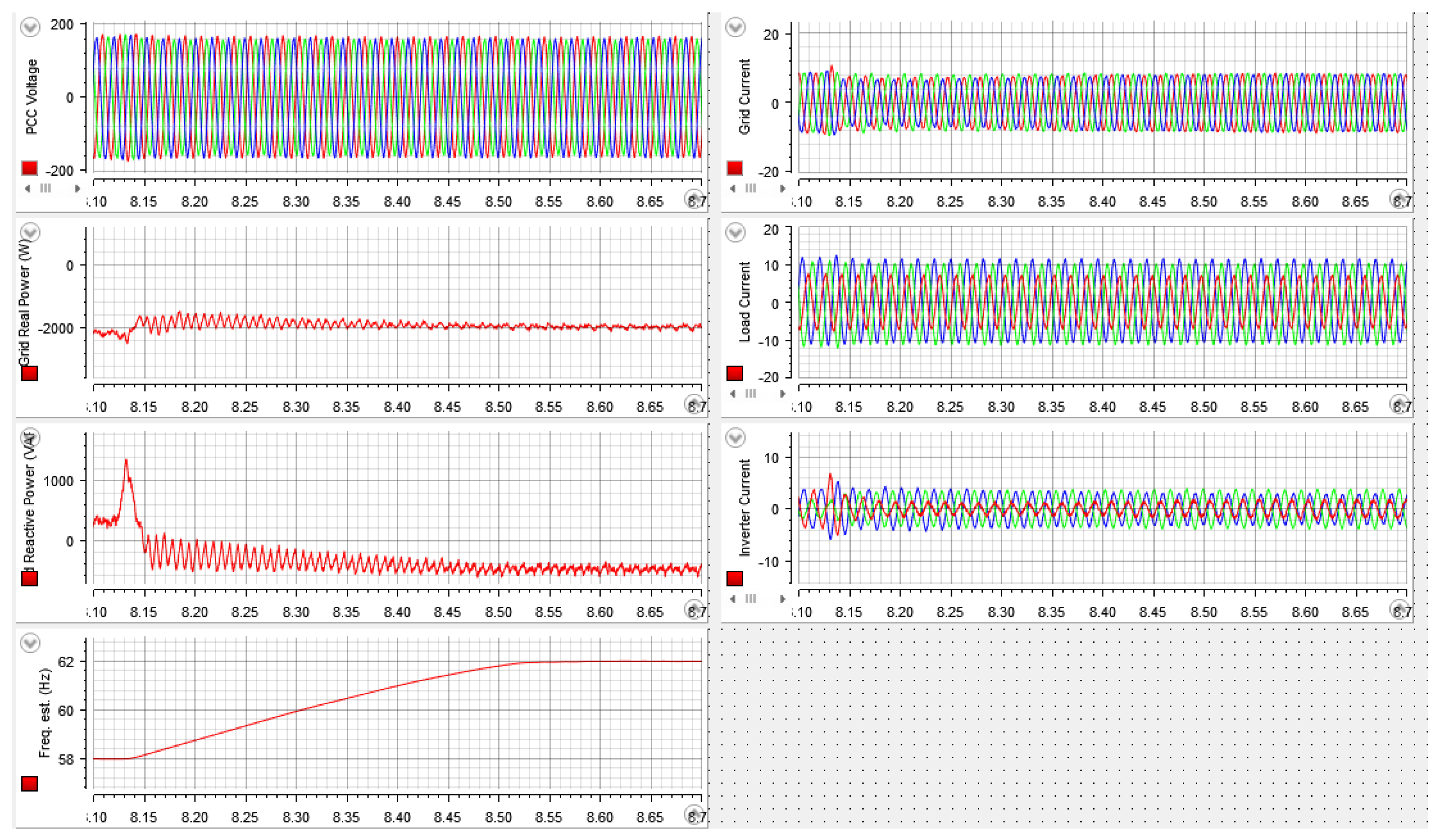
5.1. Simulation Results

The effectiveness and performance of the proposed control methodology were evaluated using simulations conducted in Simulink-MATLAB. The simulation results of the frequency estimator are shown in Figure 7. Figure 8 demonstrates the system’s response to an unbalanced resistive load connected to the grid and unbalanced grid impedance. The resulting unbalanced V P C C and i g led to fluctuations in the active power (P) and reactive power (Q), thereby impacting the performance of the other loads connected to the grid.
The SAPF was activated and began operating at a grid frequency of 60 Hz at t = 0.1 s. Within milliseconds, i g and V P C C were balanced, leading to a marked reduction in the fluctuations in P and Q. At t = 0.2 s, the grid frequency was then shifted to 58 Hz, and later to 62 Hz at t = 0.4 s. As depicated in Figure 8, the frequency estimator detected these changes within a few milliseconds. Following this, the PIR controller adjusted its parameters, enabling the SAPF system to efficiently accommodate the frequency changes.

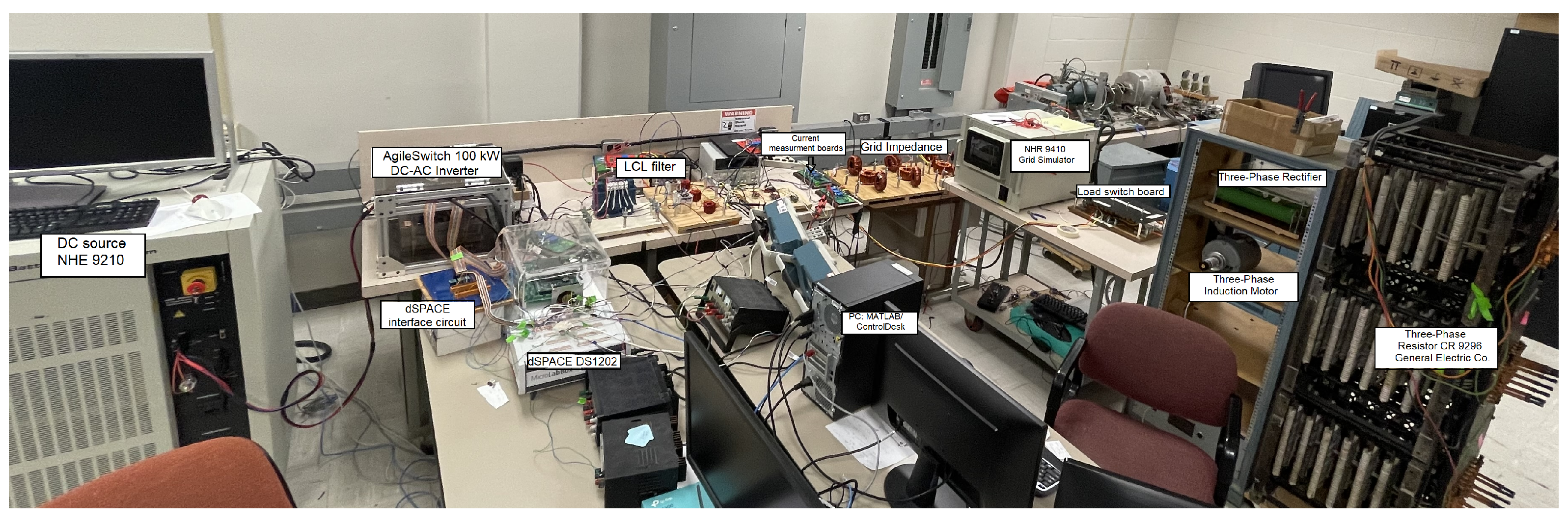
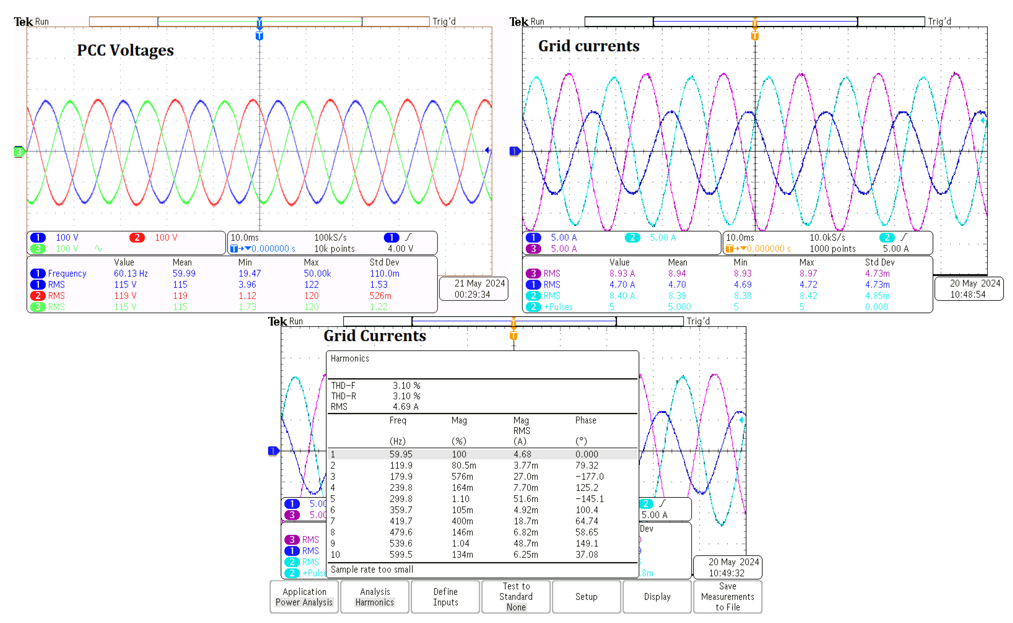
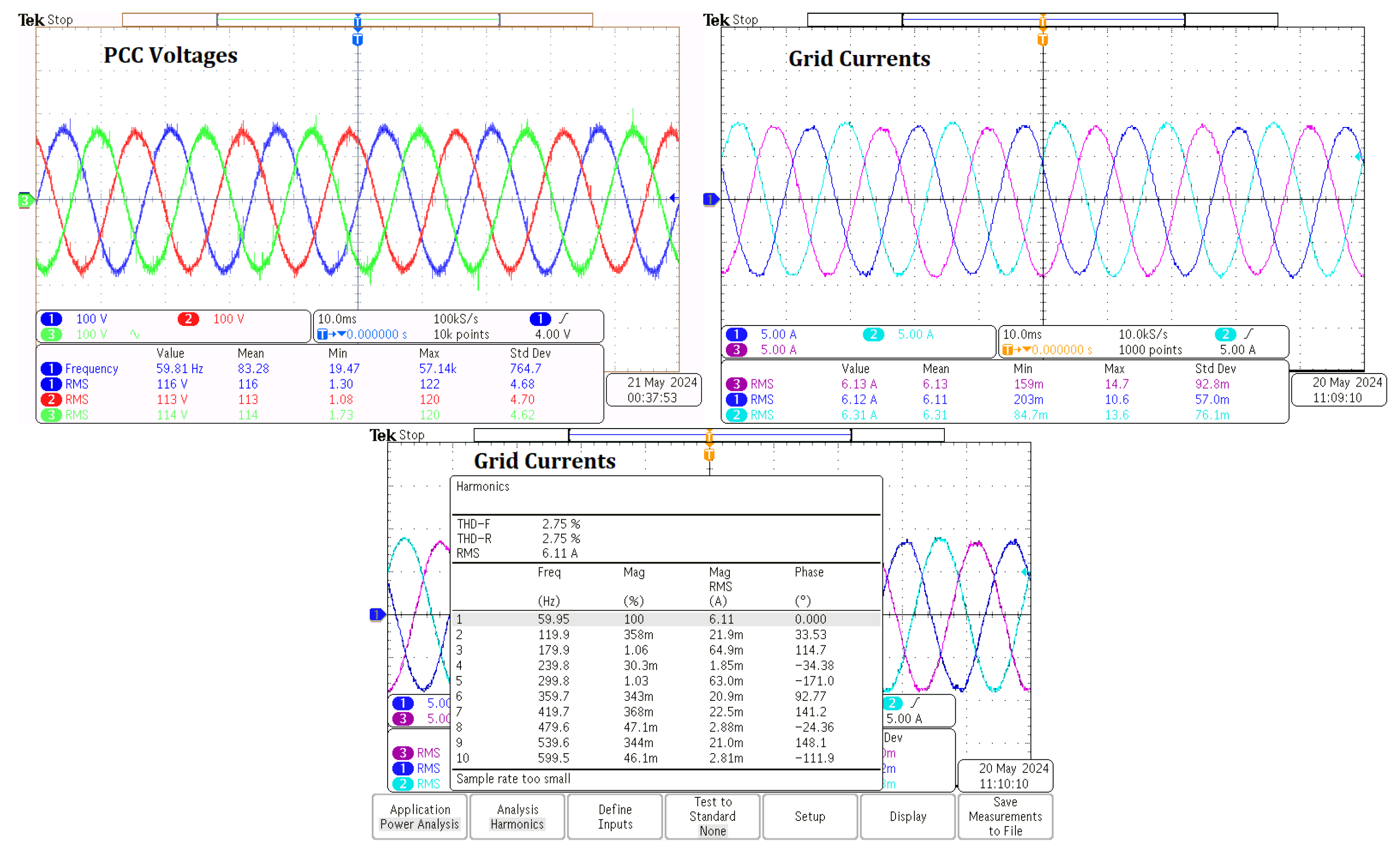
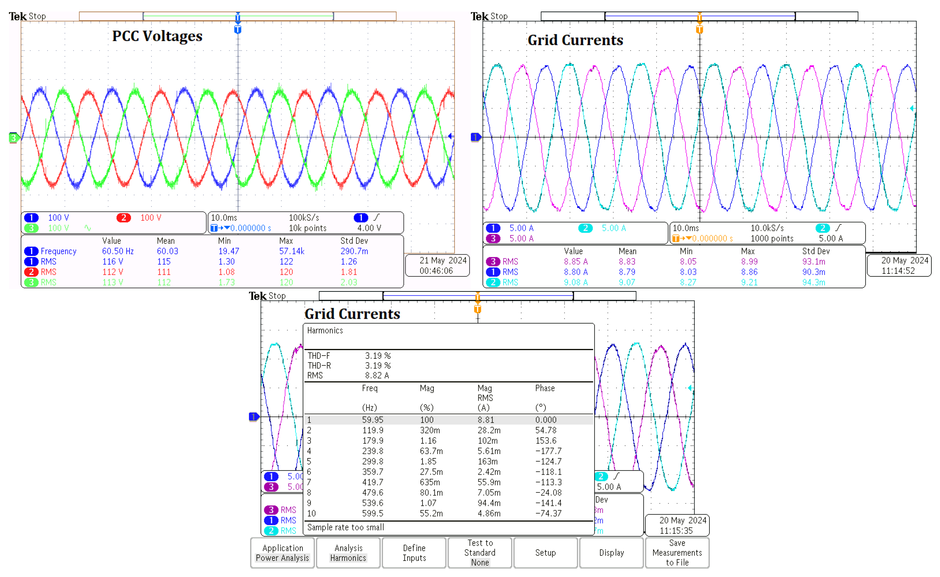
5.2. Hardware Results

The load setup included three distinct components: a three-phase resistive load bank, a three-phase rectifier connected to a resistive load, and a three-phase induction motor. The experiment was carried out on the testbed across three different scenarios. In all scenarios, the grid impedance was assumed to be unbalanced, leading to an unbalanced V P C C and i g . The experimental results were captured using a Tektronix MDO3024 oscilloscope and the DS1202 ControlDesk. Data were recorded both before and after enabling the proposed SAPF.
The NHR 9410, a regenerative grid simulator system, is a three-phase programmable AC voltage source capable of operating in either balanced or unbalanced three-phase configurations. It can supply or absorb power as required, making it ideal for simulating various grid conditions. The AgileSwitch 100 kW inverter, used in this experiment, is a three-phase DC-AC inverter designed to handle high power levels of up to 100 kW. For this experiment, the inverter was operated at a switching frequency of 5 kHz.
The dSPACE DS1202 real-time interface (RTI) platform was utilized to implement the control system. The DS1202 provides flexible input and output configurations and seamlessly integrates with MATLAB/Simulink through its built-in tools. This compatibility allows the controller developed and tested in the simulation environment to be directly implemented in hardware, streamlining the experimental process.
The NHR 9210 DC source, capable of supplying up to 12 kW at 600 V DC, was configured to provide 400 V DC for this experiment. Like the NHR 9410, it can both supply and absorb power as needed, adding versatility to the setup.
Custom-designed measurement boards were used to monitor voltage and current levels. These boards carefully scale high-voltage and current values down to a range of −10 V to +10 V, suitable for the analog-to-digital converter (ADC) ports of the dSPACE DS1202, which cannot directly process high-voltage or current inputs.
A Tektronix MDO3024 oscilloscope was employed to capture the waveforms of three-phase voltages and currents. Additionally, the MDO3024 provides functionality to measure the total harmonic distortion (THD), enabling precise analysis of the experimental results.
To detect the frequency variations of 60 Hz, 58 Hz, and 62 Hz and to ensure stable grid currents and PCC voltages at each of these frequencies, a frequency detection mechanism was integrated into the control system

5.2.1. Unbalanced Three-Phase Resistive Load

The SAPF was tested under an unbalanced three-phase resistive load with resistance values of 8 , 16 , and 32 ohms for phases a, b, and c, respectively. Figure 9 shows the oscilloscope results before enabling the SAPF at a 60 Hz frequency.
After activating the proposed method at t = 2.075 s, the hardware experimental results were obtained using dSPACE ControlDesk, as shown in Figure 10. The waveforms for the V P C C , i g , and THD% of i g are shown in Figure 11. Notably, the grid frequency accurately estimated the 60 Hz grid frequency, and the SAPF balanced V P C C and i g .
The grid frequency was changed from 58 Hz to 62 Hz at t = 8.13 s as shown in Figure 12; it took around 35 ms for the controller to detect the frequency change and stabilize at the new steady-state performance. The PIR controller modified its parameters in response to the frequency change and the information provided by the frequency estimator.
The NHR 9400 grid simulator platform was used to obtain the data shown in Figure 13 under frequencies of 58 Hz and 62 Hz. As shown in the figure, the grid currents will be balanced, and the power delivered by each phase stays nearly constant, showing only slight fluctuations. These findings validate that the proposed method performs effectively and can adapt to frequency variations.

5.2.2. Three-Phase Rectifier with a Resistor Load

The SAPF underwent testing under the operation of a three-phase rectifier with a 100 ohm resistor load. Experimental observations, captured through oscilloscope measurements before enabling the SAPF, are illustrated in Figure 14. Subsequent to the switching on of the SAPF, the experimental outcomes, depicted in Figure 15, were recorded at a 62 Hz grid frequency.
Pre-SAPF activation, the THD% was measured at approximately 50.8%. Upon SAPF activation, a notable reduction in THD% to approximately 18.4% was observed. Additionally, a discernible enhancement in the voltage waveform at the PCC was evident post-SAPF activation compared to its pre-activation state.
Following the initiation of the proposed methodology at t = 7.15 s, hardware experimental data were acquired via the dSPACE ControlDesk, as illustrated in Figure 16. Remarkably, the SAPF effectively stabilized and attenuated harmonic distortions in both i g and i P C C . Concurrently, the frequency estimator accurately identified the system frequency of 62 Hz.

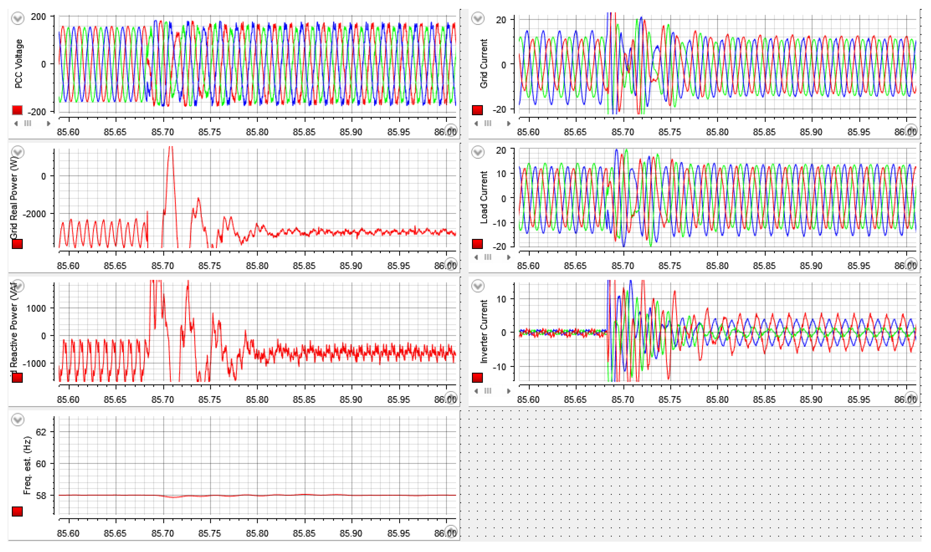
5.2.3. Three-Phase Induction Motor, Three-Phase Rectifier with a Resistor, and Unbalanced Three-Phase Resistive Loads

The SAPF underwent comprehensive testing under various operating conditions, including the parallel operation of the three loads: a three-phase induction motor, a three-phase rectifier with a 100 ohm resistor, and unbalanced three-phase resistive loads with resistances of 32, 16, and 8 ohms for phases a, b, and c, respectively. Experimental observations, obtained through oscilloscope measurements before switching on the SAPF, are depicted in Figure 17. After switching on the SAPF, the experimental outcomes, as illustrated in Figure 18, were recorded at a system frequency of 58 Hz. The frequency estimator was able to accurately and successfully identify the grid frequency.
Pre-SAPF activation, the THD% was approximately 6.16%. Following SAPF activation, a discernible reduction in THD% to approximately 3.19% was observed. Additionally, a significant improvement in the voltage waveform at the PCC was evident post-activation compared to its pre-activation state.
Upon initiating the proposed methodology at t = 85.68 s, the hardware experiments using the dSPACE ControlDesk are shown in Figure 19. Remarkably, the SAPF effectively stabilized and mitigated harmonic distortions in both grid currents and PCC voltages.
To calculate the error analysis, the following formula was utilized:
% Relative Error = | Experimental Simulated Experimental | × 100 %
The relative error for i g and V p c c utilizing Equation (14) for all three cases is shown in Table 2.

6. Conclusions

This paper disucsses the significant impact of power system frequency fluctuations and harmonic distortion, primarily from nonlinear loads such as rectifiers, on power quality and efficiency. The three-phase SAPF is essential for mitigating these issues, improving system stability, and supporting the goals of emerging consumer energy management technologies focused on efficiency and sustainability.
A novel frequency adaptive control scheme for SAPF has been proposed, along with the development of a PIR controller, which has been shown to offer enhanced performance, characterized by reduced overshoot and steady-state error. Notably, a voltage sensorless control method for the shunt APF has been introduced, requiring only current measurements to determine reference currents for the inverter, thus simplifying implementation. The approach developed in this study has demonstrated effective harmonic compensation and stabilization of systems across varying grid frequencies, addressing the limitations of traditional fixed-frequency control methods. Additionally, the study encompasses complex load scenarios, including unbalanced grid conditions and diverse nonlinear loads such as three-phase rectifiers and induction motors, which increase system imbalances and elevate THD% in PCC voltages and grid currents.
The potential for this adaptive control solution to enhance the performance of future power systems has been highlighted, particularly in the context of integrating grid-forming inverter-based resources (IBRs). Further advancements in SAPF technology will be necessary to support its application in sustainable and energy-efficient consumer power systems.

Author Contributions

Conceptualization, H.G., M.A. and R.M.N.; methodology, H.G.; software, H.G.; validation, H.G., M.A., X.Y., S.S., and R.M.N.; formal analysis, H.G.; investigation, H.G., M.A., X.Y., S.S., and R.M.N.; supervision, R.M.N. All authors have read and agreed to the published version of the manuscript.

Funding

This research received no external funding.

Data Availability Statement

The original contributions presented in the study are included in the article, further inquiries can be directed to the corresponding author.

Conflicts of Interest

The authors declare no conflicts of interest.

References

  1. Gupta, N.; Singh, S.P.; Dubey, S.P. Neural network based shunt active filter for harmonic and reactive power compensation under non-ideal mains voltage. In Proceedings of the 2010 5th IEEE Conference on Industrial Electronics and Applications, Taichung, Taiwan, 15–17 June 2010; pp. 370–375. [Google Scholar] [CrossRef]
  2. Singh, B.; Al-Haddad, K.; Chandra, A. A review of active filters for power quality improvement. IEEE Trans. Ind. Electron. 1999, 46, 960–971. [Google Scholar] [CrossRef]
  3. Salmerón, P.; Litrán, S.P. A Control Strategy for Hybrid Power Filter to Compensate Four-Wires Three-Phase Systems. IEEE Trans. Power Electron. 2010, 25, 1923–1931. [Google Scholar] [CrossRef]
  4. Lam, C.-S.; Choi, W.-H.; Wong, M.-C.; Han, Y.-D. Adaptive DC-Link Voltage-Controlled Hybrid Active Power Filters for Reactive Power Compensation. IEEE Trans. Power Electron. 2012, 27, 1758–1772. [Google Scholar] [CrossRef]
  5. Watanabe, E.H.; Aredes, M.; Afonso, J.L.; Pinto, J.G.; Monteiro, L.F.C.; Akagi, H. Instantaneous p–q power theory for control of compensators in micro-grids. In Proceedings of the 2010 International School on Nonsinusoidal Currents and Compensation, Lagow, Poland, 15–18 June 2010; pp. 17–26. [Google Scholar] [CrossRef]
  6. Sozański, K.P. Control circuit for active power filter with an instantaneous reactive power control algorithm modification. In Proceedings of the 2010 International School on Nonsinusoidal Currents and Compensation, Lagow, Poland, 15–18 June 2010; pp. 230–233. [Google Scholar] [CrossRef]
  7. Lyons, R.; Howard, C. Improvements to the Sliding Discrete Fourier Transform Algorithm. IEEE Signal Process. Mag. 2021, 38, 119–127. [Google Scholar] [CrossRef]
  8. Sozanski, K.; Jarnut, M. Three-phase active power filter using the sliding DFT control algorithm. In Proceedings of the 2005 European Conference on Power Electronics and Applications, Dresden, Germany, 11–14 September 2005; p. 10. [Google Scholar] [CrossRef]
  9. Karimi, S.; Poure, P.; Saadate, S. High performances reference current generation for shunt active filter under distorted and unbalanced conditions. In Proceedings of the IEEE—PESC Power Electronics Specialists Conference, Rhodes, Greece, 15–19 June 2008; pp. 195–201. [Google Scholar]
  10. Song, H.-S.; Joo, I.-W.; Nam, K. Source voltage sensorless estimation scheme for PWM rectifiers under unbalanced conditions. IEEE Trans. Ind. Electron. 2003, 50, 1238–1245. [Google Scholar] [CrossRef]
  11. Ahmed, K.H.; Massoud, A.M.; Finney, S.J.; Williams, B.W. Sensorless current control of three-phase inverter-based distributed generation. IEEE Trans. Power Del. 2009, 24, 919–929. [Google Scholar] [CrossRef]
  12. Malinowski, M.; Bernet, S. A Simple Voltage Sensorless Active Damping Scheme for Three-Phase PWM Converters With an LCL Filter. IEEE Trans. Ind. Electron. 2008, 55, 1876–1880. [Google Scholar] [CrossRef]
  13. Al-Gahtani, S.; Nelms, R.M. A New Voltage Sensorless Control Method for a Shunt Active Power Filter for Unbalanced Conditions. In Proceedings of the 2019 IEEE International Conference on Environment and Electrical Engineering and 2019 IEEE Industrial and Commercial Power Systems Europe (EEEIC/I & CPS Europe), Genova, Italy, 11–14 June 2019; pp. 1–6. [Google Scholar] [CrossRef]
  14. Al-Gahtani, S.; Nelms, R.M. Performance of a Shunt Active Power Filter for Unbalanced Conditions Using Only Current Measurements. Energies 2021, 14, 397. [Google Scholar] [CrossRef]
  15. Alathamneh, M.; Ghanayem, H.; Nelms, R.M. Power Control of a Three-phase Grid-connected Inverter using a PI Controller under Unbalanced Conditions. In Proceedings of the SoutheastCon 2022, Mobile, AL, USA, 26 March–3 April 2022; pp. 447–452. [Google Scholar] [CrossRef]
  16. Alathamneh, M.; Ghanayem, H.; Nelms, R.M. Bidirectional Power Control for a Three-Phase Grid-Connected Inverter under Unbalanced Grid Conditions Using a Proportional-Resonant and a Modified Time Domain Symmetrical Components Extraction Method. Energies 2022, 15, 9564. [Google Scholar] [CrossRef]
  17. Alepuz, S.; Busquets-Monge, S.; Bordonau, J.; Martínez-Velasco, J.A.; Silva, C.A.; Pontt, J.; Rodríguez, J. Control Strategies Based on Symmetrical Components for Grid-Connected Converters Under Voltage Dips. IEEE Trans. Ind. Electron. 2009, 56, 2162–2173. [Google Scholar] [CrossRef]
  18. Ivanović, Z.R.; Adžić, E.M.; Vekić, M.S.; Grabić, S.U.; Čelanović, N.L.; Katić, V.A. HIL Evaluation of Power Flow Control Strategies for Energy Storage Connected to Smart Grid Under Unbalanced Conditions. IEEE Trans. Power Electron. 2012, 27, 4699–4710. [Google Scholar] [CrossRef]
  19. Srinath, N.S.; Sundarabalan, C.K.; Sharma, J.; Balasundar, C.; Vijayakumar, V. Quasi newton least mean fourth control for multifunctional grid tied solar photovoltaic system. Sustain. Energy Technol. Assessments 2023, 57, 103272. [Google Scholar] [CrossRef]
  20. Appala Naidu, T.; Arya, S.R.; Maurya, R.; Padmanaban, S. Performance of DVR using optimized PI controller based gradient adaptive variable step LMS control algorithm. IEEE J. Emerg. Sel. Top. Ind. Electron. 2021, 2, 155–163. [Google Scholar] [CrossRef]
  21. Naidu, T.A.; Arya, S.R.; Maurya, R.; Singh, B.; Al-Durra, A. Combined variable step size LMS for DVR with error regulator gain tuning through ant-lion optimization. In Proceedings of the IEEE Industry Applications Society Annual. Meeting (IAS), Detroit, MI, USA, 10–16 October 2020; pp. 1–8. [Google Scholar]
  22. Routray, A.; Pradhan, A.K.; Rao, K.P. A novel Kalman filter for frequency estimation of distorted signals in power systems. IEEE Trans. Instrum. Meas. 2002, 51, 469–479. [Google Scholar] [CrossRef]
  23. Germani, A.; Manes, C.; Palumbo, P. Polynomial extended Kalman filter. IEEE Trans. Autom. Control 2005, 50, 2059–2064. [Google Scholar] [CrossRef]
  24. Yang, X.; Zhang, Z.; Xu, M.; Li, S.; Zhang, Y.; Zhu, X.-F.; Ouyang, X.; Alù, A. Digital non-foster-inspired electronics for broadband impedance matching. Nat. Commun. 2024, 15, 4346. [Google Scholar] [CrossRef] [PubMed]
  25. Tian, W.; Wang, L.; Yu, J.; Lv, Y.; Zhang, S.; Xu, Q.; Gao, B. A hybrid impedance matching network for underwater acoustic transducers. IEEE Trans. Power Electron. 2023, 38, 7622–7633. [Google Scholar] [CrossRef]
  26. Ghanayem, H.; Alathamneh, M.; Nelms, R.M. Adaptive PIR Current Controllers for Torque Ripple Reduction of PMSM using Decoupled Speed and Flux Control. In Proceedings of the 2023 IEEE 14th Annual Ubiquitous Computing, Electronics & Mobile Communication Conference (UEMCON), New York, NY, USA, 12–14 October 2023; pp. 440–444. [Google Scholar] [CrossRef]
  27. Yang, X.; Zhou, H.; Alathamneh, M.; Nelms, R.M. An Evolutionary Annealing–Simplex Method for Inductance Value Selection for LCL Filters. Energies 2023, 16, 4192. [Google Scholar] [CrossRef]
Figure 1. Schematic representation of SAPF.
Energies 18 00116 g001
Figure 2. SAPF control employing the SCEM [13].
Energies 18 00116 g002
Figure 3. Shunt APF control utilizing the PIR controller.
Energies 18 00116 g003
Figure 4. Frequency estimation technique using zero-crossing method.
Energies 18 00116 g004
Figure 5. Frequency-adaptive PIR controller using only current measurements in SAPF.
Energies 18 00116 g005
Figure 6. Test system setup.
Energies 18 00116 g006
Figure 7. The simulation results of the proposed frequency estimator.
Energies 18 00116 g007
Figure 8. Simulation results under varying frequencies—unbalanced three-phase resistive load.
Energies 18 00116 g008
Figure 9. The oscilloscope hardware experimental results before enabling SAPF for V P C C , i g , and the THD in i g under unbalanced three-phase resistive load.
Energies 18 00116 g009
Figure 10. The ControlDesk experimental results under 60 Hz.
Energies 18 00116 g010
Figure 11. The oscilloscope hardware experimental results after enabling SAPF for V P C C , i g , and the THD in i g under unbalanced three-phase resistive load.
Energies 18 00116 g011
Figure 12. The ControlDesk experimental results show a frequency variation from 58 Hz to 62 Hz.
Energies 18 00116 g012
Figure 13. The grid simulator: NHR 9400 experimental results under 58 Hz and 62 Hz.
Energies 18 00116 g013
Figure 14. The oscilloscope hardware experimental results before enabling SAPF for V P C C , i g , and the THD in i g under three-phase rectifier with a resistor load.
Energies 18 00116 g014
Figure 15. The oscilloscope hardware experimental results after enabling SAPF for V P C C , i g , and the THD in i g under three-phase rectifier with a resistor load.
Energies 18 00116 g015
Figure 16. The ControlDesk experimental results with 62 Hz frequency under a three-phase rectifier with a resistor load.
Energies 18 00116 g016
Figure 17. The oscilloscope hardware experimental results before enabling SAPF for V P C C , i g , and the THD in i g under all three loads.
Energies 18 00116 g017
Figure 18. The oscilloscope hardware experimental results after enabling SAPF for V P C C , i g , and the THD in i g under all three loads.
Energies 18 00116 g018
Figure 19. The ControlDesk experimental results with 58 Hz frequency under all three loads.
Energies 18 00116 g019
Table 1. Test system specifications.
fGrid frequency58, 60, 62 Hz
V g Grid phase voltage120 V RMS
f s w Switching frequency5 kHz
V d c DC source voltage400 V
L1Inverter side inductance2.3 mH
L2Grid side inductance0.58 mH
CFilter capacitance15 μ F
RDamping resistor1.5 Ω
Z g , a b c Unbalanced grid Impedance for phases a, b, c5.1, 4.5, 3 mH
R L , a b c Three-phase load8, 16, 32 Ω
R r e c t i f i e r Three-phase AC-DC rectifier resistor100 Ω
Table 2. Relative error calculation.
LoadRelative Error of i g Relative Error of V pcc
Unbalanced R-Load0.334%0.968%
Three-phase Rectifier Load0.667%1.093%
Three-phase Induction Motor,0.957%2%
Three-phase Rectifier,
and Unbalanced R-Load
Disclaimer/Publisher’s Note: The statements, opinions and data contained in all publications are solely those of the individual author(s) and contributor(s) and not of MDPI and/or the editor(s). MDPI and/or the editor(s) disclaim responsibility for any injury to people or property resulting from any ideas, methods, instructions or products referred to in the content.

