Article

Non-Contact Wind Turbine Blade Crack Detection Using Laser Doppler Vibrometers

1
Department of Mechanical Engineering, Rowan University, Glassboro, NJ 08028, USA
2
Aerospace, Physics, and Space Sciences, Florida Institute of Technology, Melbourne, FL 08028, USA
*
Author to whom correspondence should be addressed.
Energies 2024, 17(9), 2165; https://doi.org/10.3390/en17092165
Submission received: 22 March 2024 / Revised: 25 April 2024 / Accepted: 29 April 2024 / Published: 1 May 2024
(This article belongs to the Special Issue Latest Developments in Offshore Wind Technologies)

Abstract

:
In response to the growing global demand for both energy and a clean environment, there has been an unprecedented rise in the utilization of renewable energy. Wind energy plays a crucial role in striving for carbon neutrality due to its eco-friendly characteristics. Despite its significance, wind energy infrastructure is susceptible to damage from various factors including wind or sea waves, rapidly changing environmental conditions, delamination, crack formation, and structural deterioration over time. This research focuses on investigating non-destructive testing (NDT) of wind turbine blades (WTBs) using approaches based on the vibration of the structures. To this end, WTBs are first made from glass fiber-reinforcement polymer (GFRP) using composite molding techniques, and then a short pulse is generated in the structure by a piezoelectric actuator made from lead zirconate titanate (PZT-5H) to generate guided waves. A numerical approach is presented based on solving the elastic time-harmonic wave equations, and a laser Doppler vibrometer (LDV) is utilized to collect the vibrational data in a remote manner, thereby facilitating the crack detection of WTBs. Subsequently, the wave propagation characteristics of intact and damaged structures are analyzed using the Hilbert–Huang transformation (HHT) and fast Fourier transformation (FFT). The results reveal noteworthy distinctions in damaged structures, where the frequency domain exhibits additional components beyond those identified by FFT, and the time domain displays irregularities in proximity to the crack region, as detected by HHT. The results suggest a feasible approach to detecting potential cracks of WTBs in a non-contact and reliable way.

1. Introduction

As a result of the growing need for cleaner energy and a more sustainable environment, there has been a rising trend in the adoption of renewable sources that cause less harm to our planet compared to non-renewable sources in recent decades. Wind energy is leading the revolution as one of the major renewable power sources, and wind power has become a prevalent way of obtaining clean electric power nowadays [1]. Wind turbines have become a hallmark of clean energy and are integral components of the renewable energy landscape, existing both onshore and offshore [2].
Wind turbines are often constructed in locations with harsh environmental conditions, and they often face intense forces generated by changing winds, storms, and waves that could result in various structural damages such as cracks forming, layers separating, and gradual wear over time. One critical component prone to such damages is the blade, which is intricately constructed in conjunction with other parts of the turbine. The blade serves as the primary component responsible for capturing wind energy and converting it into rotational motion, making it particularly susceptible to the forces exerted by the surrounding environment. Damage to the blades can compromise the overall efficiency and functionality of the turbine, highlighting the importance of operation and maintenance strategies to mitigate these risks [3,4]. Advancements in maintenance strategies and risk mitigation are continuously improving the reliability of wind turbines to make them more suitable and sustainable sources of electrical power [5].
Regular condition monitoring and inspection of WTBs are crucial for efficiency, safety, and longevity in wind energy systems. To this end, proactive monitoring aims to identify and address structural issues early on, minimizing the risk of catastrophic failures that could lead to injuries or environmental damage. This methodology also supports predictive maintenance strategies, reducing downtime and overall maintenance costs while extending the lifespan of the blades [6,7]. It is also called condition-based maintenance, involving the application of advanced diagnostic techniques, of which predictive maintenance has been achieved using machine learning techniques to build inductive models that learn the underlying set of structures in the supervisory control and data acquisition system data of WTBs, predicting incipient faults and anomalies [8]. Within this context, conventional monitoring methods prove costly and challenging to implement for constant checking. For instance, sensors placed inside the WTBs need to be changed often and use extra external power, adding costs for operation and maintenance. LiDAR systems that do not touch the blades are useful for monitoring the exterior, but they cannot detect subsurface damage including internal cracks [9]. Reddy et al. [10] used artificial intelligence-based image analytics to monitor WTBs. This research involved inspecting WTBs using drones and its framework operated on top of TensorFlow and utilizing images captured by drones to train a neural network model. Optical approaches are another adopted method that can only detect surface cracks and perform surface inspection of WTBs [11]. Conversely, acoustic solutions include two existing methods to inspect WTBs. One of them is acoustic emission testing, in which microphones are placed on the structures to capture frequencies generated by internal stress to identify structural defects. Another is elastic wave propagation, which involves sending controlled sound waves by piezoelectric transducers through materials to evaluate their structural integrity [12,13,14]. In response to the need for this, our suggested research puts itself at the forefront of finding better ways to monitor WTBs with the help of LDVs as an NDT [15]. Some research works have dealt with this issue; for example, Dilek et al. [16] developed an automated scanning system to conduct measurements on WTBs with higher efficiency. The results also show that crucial dynamic features of the system, such as eigenfrequencies and mode shapes, can be precisely derived from the analysis results. In another study, LDV measurements were carried out on wind turbines to distinguish different operating conditions, and a simulation was made to validate the results of this study [17]. Then, spectral peaks that correspond to the blade eigenfrequencies, blade-passing frequency, and tower bending modes were identified. Similarly, Vuye et al. [18] used LDV to measure the displacement of a fan blade and calculate the dynamic strain distributions. Then, the results were validated by finite element model and strain gauge measurement. For more details, one can see [19,20,21,22].
In order to identify possible structural damage, it is essential to employ data processing techniques. This involves the application of methods and algorithms to analyze and interpret data, enabling the detection of potential issues within the structure. In this respect, HHT stands out as a nonlinear technique for extracting time–frequency content from unstable signals. The technique involves adaptively decomposing a signal into intrinsic mode functions (IMFs), extracting instantaneous frequency and magnitude using the Hilbert transform. The HHT process comprises three steps: IMF extraction through empirical mode decomposition, Hilbert transform on the IMFs, and estimation of instantaneous frequency and complex envelope. This method, tailored to our wind turbine blade situation, offers a thorough analysis of unstable signals, making it a valuable tool in fault detection for WTBs experiencing variable-speed conditions [23,24]. Herein, studies related to the application of the HHT to detect cracks in the structures are cited. HHT was used for monitoring the cracks in concrete by Zhang et al. [25], and IMF2 was substantiated as the most effective IMF in crack monitoring. Other studies used time–frequency domain methods to capture cracks in beam-like structures [26]. They substantiated that HHT can detect even slight differences in frequencies that are not observed in time and continuous wavelet transform plots. The interested reader is referred to [27,28,29,30].
A survey of the literature shows that HHT is utilized in various engineering structures, yet its applications in WTBs remain largely unexplored. Additionally, only a few studies have been conducted to investigate cracks at different depths, including surface and deep cracks. Thereupon, this study investigates the monitoring of a WTB both numerically and experimentally. To this end, COMSOL 6.1 Multiphysics was utilized to simulate the WTB and evaluate vibrations by generating a short pulse at 200 kHz with the help of a piezoelectric actuator made from PZT-5H, measuring velocity over time. In the physical model, PZT-5H is attached to the surface of the WTB to convert electrical energy into mechanical energy, and it generates the same frequency as in the simulation. Consequently, LDV, serving as the NDT methodology, is applied to measure the velocity over time at different points. The HHT is then employed to distinguish different intrinsic mode functions (IMFs) in the time domain. Additionally, the FFT is used to show the strength of the center frequency and to make a comparison between intact and damaged structures.

2. Finite Element Method

2.1. Structural Design

The glass fiber-reinforcement polymer is usually used as the primary component of WTBs. In one study, it was substantiated that the absorption of water can impact both the mechanical performance and the overall durability of the WTBs and GFRP can also absorb moisture. Likewise, it has the ability to sustain different environmental conditions such as temperature, moisture, and saline [31]. Amano et al. [32] studied embedded layers in GFRP and compared the flexural stresses before and after healing to present a new method for creating self-healing. They stated that utilizing an embedded layer confines the catalyst to a smaller volume compared to creating the WTB in a single layer. The ability of GFRP to recover constituent materials from a thermoplastic composite is another advantage of this material in that it can replace virgin materials in the supply chain [33]. This feasibility is associated with minimizing polymer degradation, enhancing the resale value of glass fiber, and lowering labor costs.
Depicted in Figure 1, a scaled-down blade was fabricated using glass fiber-reinforced plastics (GFRPs) in line with established composite molding techniques [34,35]. The proposed WTB measured 450 mm in length and 200 mm in width with a taper ratio (TR) of 1. The composite used in the fabrication process had a Young’s modulus of E G F R P = 66.935 Pa, a Poisson’s ratio of ϑ G F R P = 0.215, and a density of ρ G F R P = 2420 kg/m3 [36]. The WTB prototype consisted of three sections attached to each other and produced by a fused deposition modeling (FDM) 3D printer. In the subsequent phase, six layers of GFRP, all aligned in a unidirectional orientation of zero degrees and summing to a total thickness of 2 mm, were utilized. The blade’s perimeter was trimmed and polished using an OMAX (Kent, WA, USA) abrasive waterjet cutting tool.

2.2. Band Structure

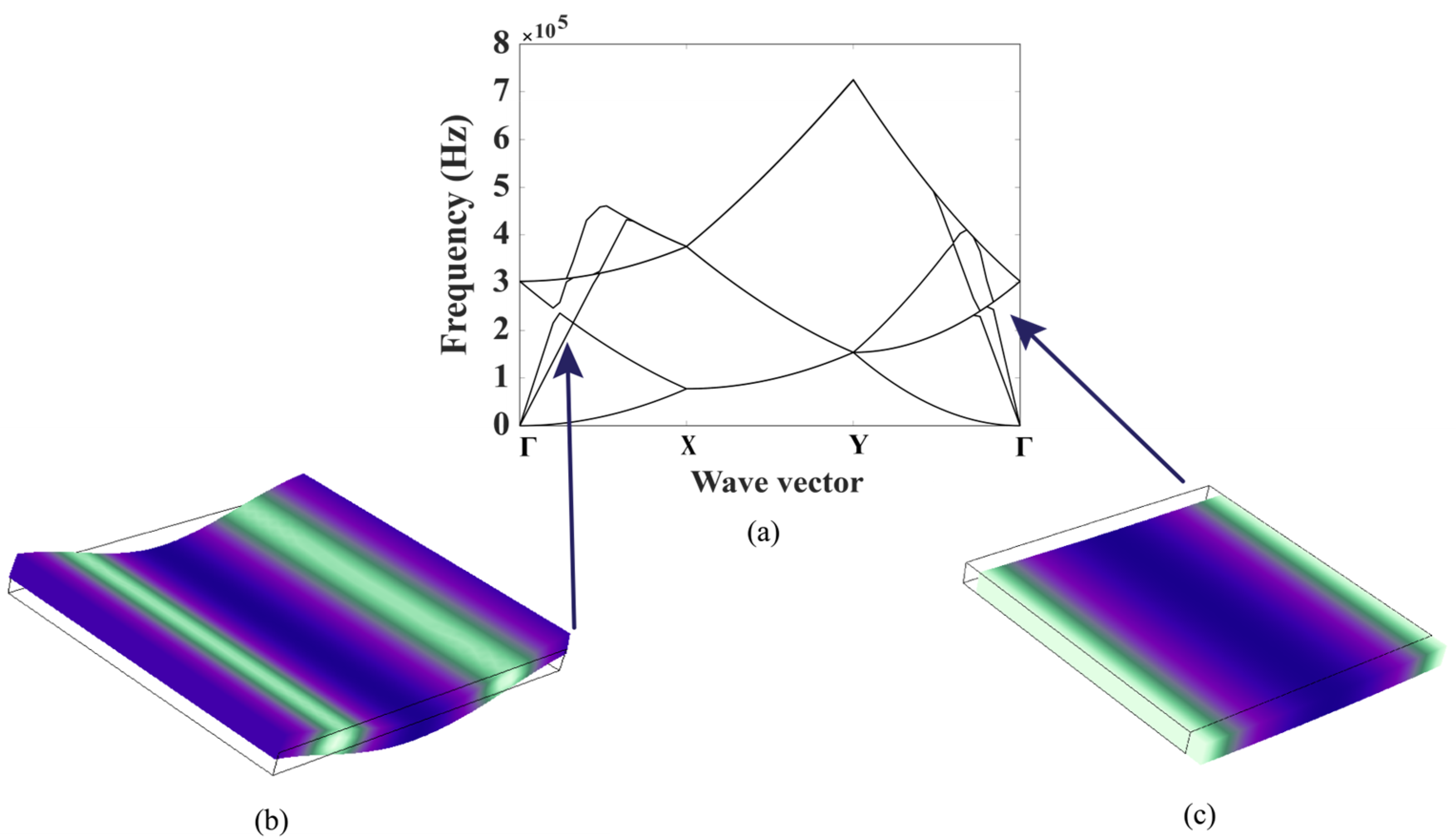
The focus of this research is on guided waves due to their convenience in measurement and sensitivity to structural defects. Figure 2 illustrates the band structure of a unit cell with dimensions of 2.5 mm in length and width and a thickness of 0.2 mm composed of a composite material interface with six layers. The dispersion characteristics calculated over frequency and wavenumber are demonstrated. In this approach, a simulation in the eigenfrequency domain is conducted using COMSOL Multiphysics 6.1 incorporating a parametric sweep for modal analysis on a unit cell composite material interface with six layers. Bloch–Floquet boundary conditions are then applied to estimate the dispersion characteristics of the unit cell, and the first six eigenfrequencies are plotted.
The simulation results reveal that multiple propagation modes coexist within the structure. Following this, guided waves are applied to the piezoelectric actuator to induce vibration in the structure. As suggested by the numerical simulations, other types of waves, such as out-of-plane and in-plane vibrations, are also generated in the second and third bands correspondingly.
Subsequently, time-domain simulations were carried out in COMSOL 6.1 Multiphysics using the Solid Mechanics module. Prescribed velocity conditions were applied for the piezoelectric actuator, which incorporated Gaussian-modulated short pulses to excite vibrations of the blade and study wave propagation characteristics. Low reflection boundaries were assigned to the edge areas to avoid undesired reflections. The simulation was conducted with a mesh size corresponding to a quarter of the wavelength. The velocities at certain points were recorded and used for extracting useful features of the WTB prototype, as will be discussed in the next section.

3. Experimental Procedure

3.1. Experimental Setup

To evaluate the effectiveness of the suggested technique for identifying cracks in WTBs, a ceramic ring piezoelectric transducer was attached to the WTB prototype to generate acoustic actuation. Custom-made wooden supports equipped with hanging strings were used to suspend the blade in mid-air in order to avoid any dampening of vibrations due to contact with support structures, thereby emulating a free boundary condition. A short pulse signal was produced by a function generator (RIGOL DG4162, Portland, OR) and amplified by an RF power amplifier (ENI 3200L, 132 Renton, WA, USA) to launch vibrational signals within the blade through the attached piezoelectric transducer. A single-point laser vibrometer LDV (SWIR Optomet Nova series, Berlin, Germany) was then employed to record the total velocity at different selected points on the blade prototype. To enhance the signal quality and maximize the signal-to-noise ratio, the blade was modified by affixing reflective tape (3M Tape, Uline, Pleasant Prairie, Wisconsin, USA), enabling precise total velocity measurements at the marked points. The LDV information was gathered using OptoGui software (https://www.optomet.com/products/software/optogui/) featuring a 1.2 kHz high-pass filter to eliminate unwanted low-frequency noise or disruptions. Subsequently, the recorded data were processed by MATLAB (2021b) for detailed analysis. The overall experimental setup is shown in Figure 3.

3.2. Correlation Factor

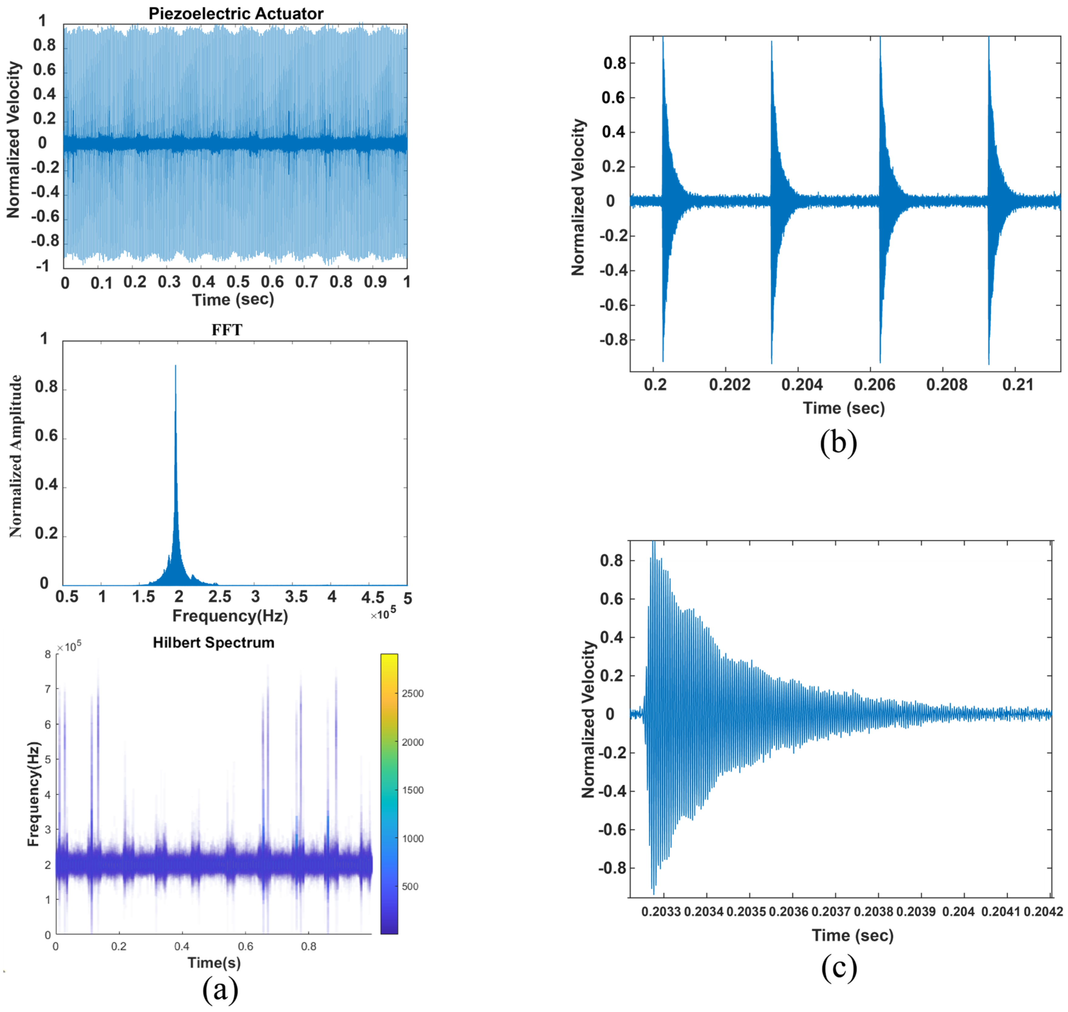
In this section, the measurement is taken directly on the piezoelectric actuator instead of the structure to verify the excitation of a short pulse in the actuator and the effectiveness of OptoGui software, and the results are presented in Figure 4. The FFT and Hilbert spectrum also verify the propagation of 200 kHz in the piezoelectric actuator in one second. Additionally, four short pulses are presented to confirm the regular propagation of short pulses, and one short pulse is used to illustrate the signal details.
Then, the HHT is applied to the original signal, and the correlation coefficients of the first four IMFs are calculated in Table 1. Generally, IMF1 has the highest correlation coefficient because it captures a more dominant and prominent feature of the signal.
After the source is actuated and guided waves begin to propagate within the structure, the signals may become complicated and noisy, depending on factors such as the distance to the actuator, location of measurement, and so on. Mode mixing, scattering, and attenuation can also take place as the propagation distance becomes larger. Consequently, obtaining wave propagation characteristics becomes challenging. With the assistance of HHT, IMF2 reveals these short pulses, providing an effective means of extracting useful features from the noisy signals. In Figure 5, compared to the measurement in Figure 4, IMF1 (the fundamental mode) remains noisy despite having the highest correlation factor. Referring to Table 1, it is evident that IMF1 has the highest correlation coefficient, making it impractical for capturing the short pulses. However, IMF2 exhibits a lower correlation factor than IMF1, indicating a higher likelihood of obtaining short pulses compared to other IMFs. Therefore, IMF2 emerges as a capable indicator for the detection of short pulses.

4. Simulation and Experiment

In this section, the vibrational signal of the intact and damaged structures is compared numerically and experimentally. Based on the elastic time-harmonic wave equations, a time-domain simulation is carried out with an excitation frequency of 200 kHz, in which one wavelength is as follows:
λ = v f ,
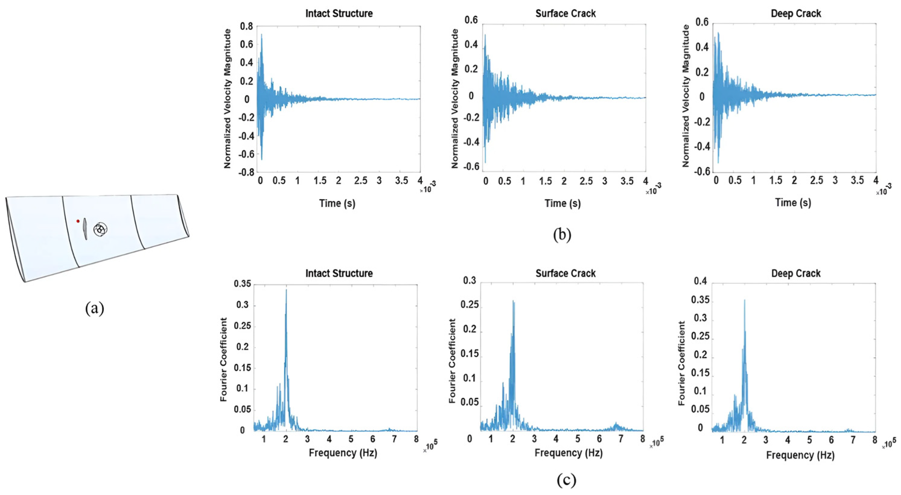
where v is the speed of the wave in the structure, approximately 5000 m/s. The center frequency, denoted as f, is set at 200 kHz, and the wavelength in this study is roughly 25 mm. The crack with a length of 30 mm is created with depths of 25% and 65% of the total thickness. The velocities on the structure before and after the crack are measured and compared in three different cases: intact structure, surface crack, and deep crack.
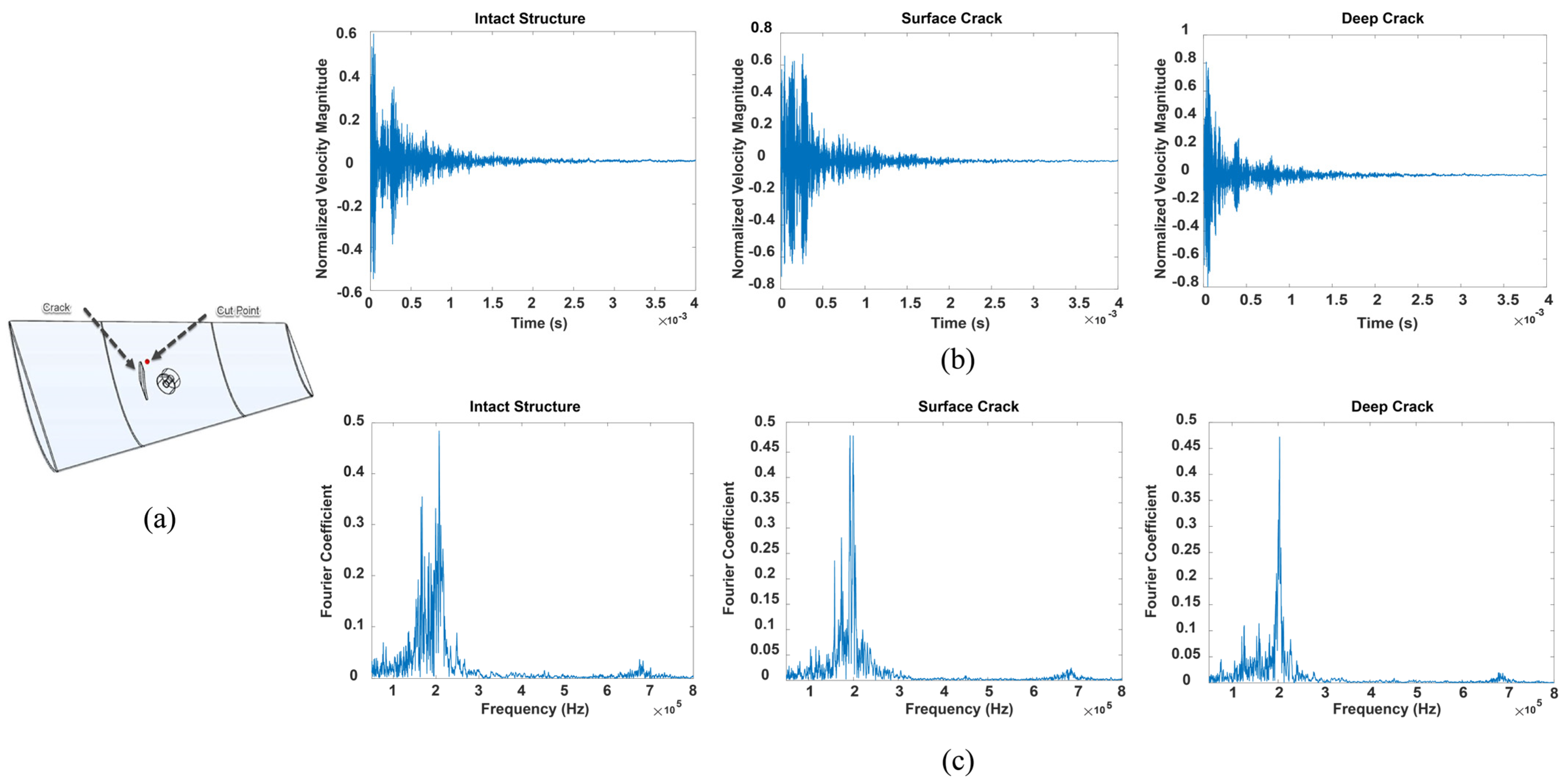
Figure 6a displays the simulation configuration, capturing the velocities in the upstream of the crack—that is, in between the acoustic actuator and the site of damage. This study investigates how the velocity varies under three distinct conditions: an undamaged structure, a structure with a surface-level crack (where the crack penetrates 25% into the blade thickness), and one with a deep crack (where the crack extends 65% into the blade thickness). The initial measurement data are shown in Figure 6b. To analyze the signals in the frequency domain, fast Fourier Transform (FFT) techniques are employed. The results, displaying Fourier coefficients across various frequencies, can be found in Figure 6c.
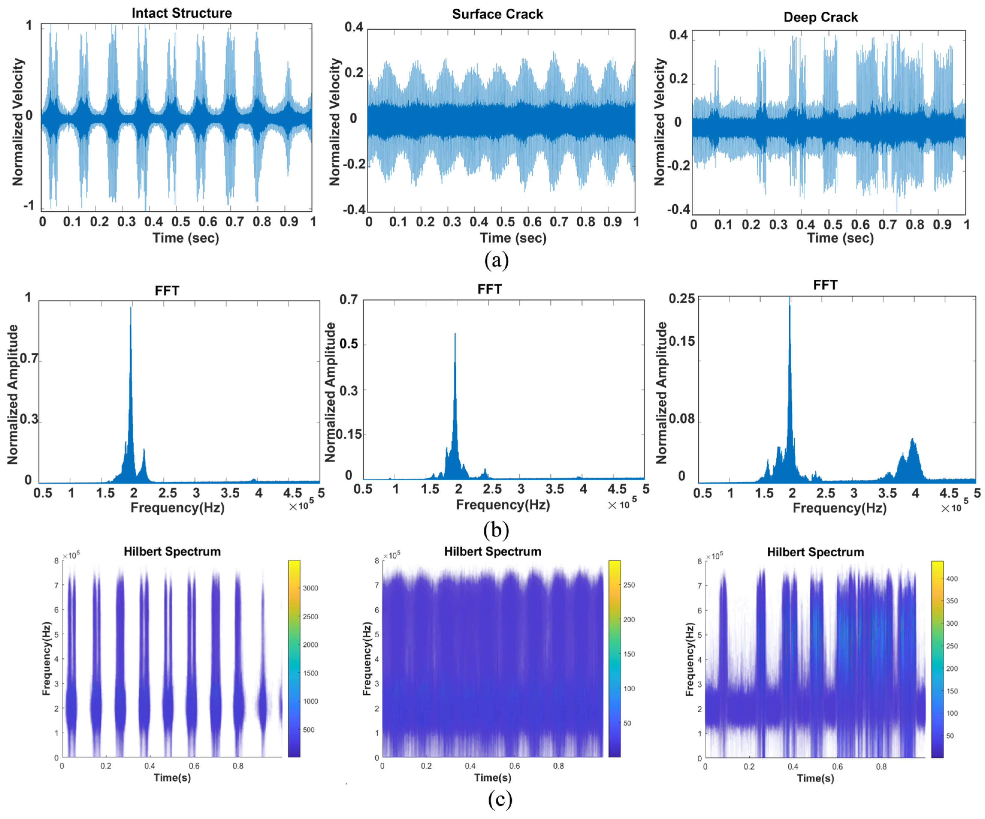
Similarly, Figure 7a presents the experiment setup before the crack, comparing velocity variation in three situations: intact structure, surface crack, and deep crack, coupled with FFT analysis. To validate the effectiveness of the measurement point, the Hilbert spectrum is presented to illustrate the time-varying frequency components in Figure 7a. Unlike Figure 4a, where the measurement is taken directly on the piezoelectric actuator and the center frequency is applied smoothly over time, one can observe, based on the Hilbert spectrum, that the frequency propagates nonlinearly in the structure in Figure 7a. This implies that the structure experiences both in-plane and out-of-plane vibrations.
Generally, when a structure has a crack, the frequency exhibits conspicuous components other than the center frequency due to the generation of nonlinear components [37]. For instance, in Figure 6c of the simulation, there are components in the frequency domain around 700 kHz. In the experiment, as shown in Figure 7b, the frequency domain has components around 400 kHz.
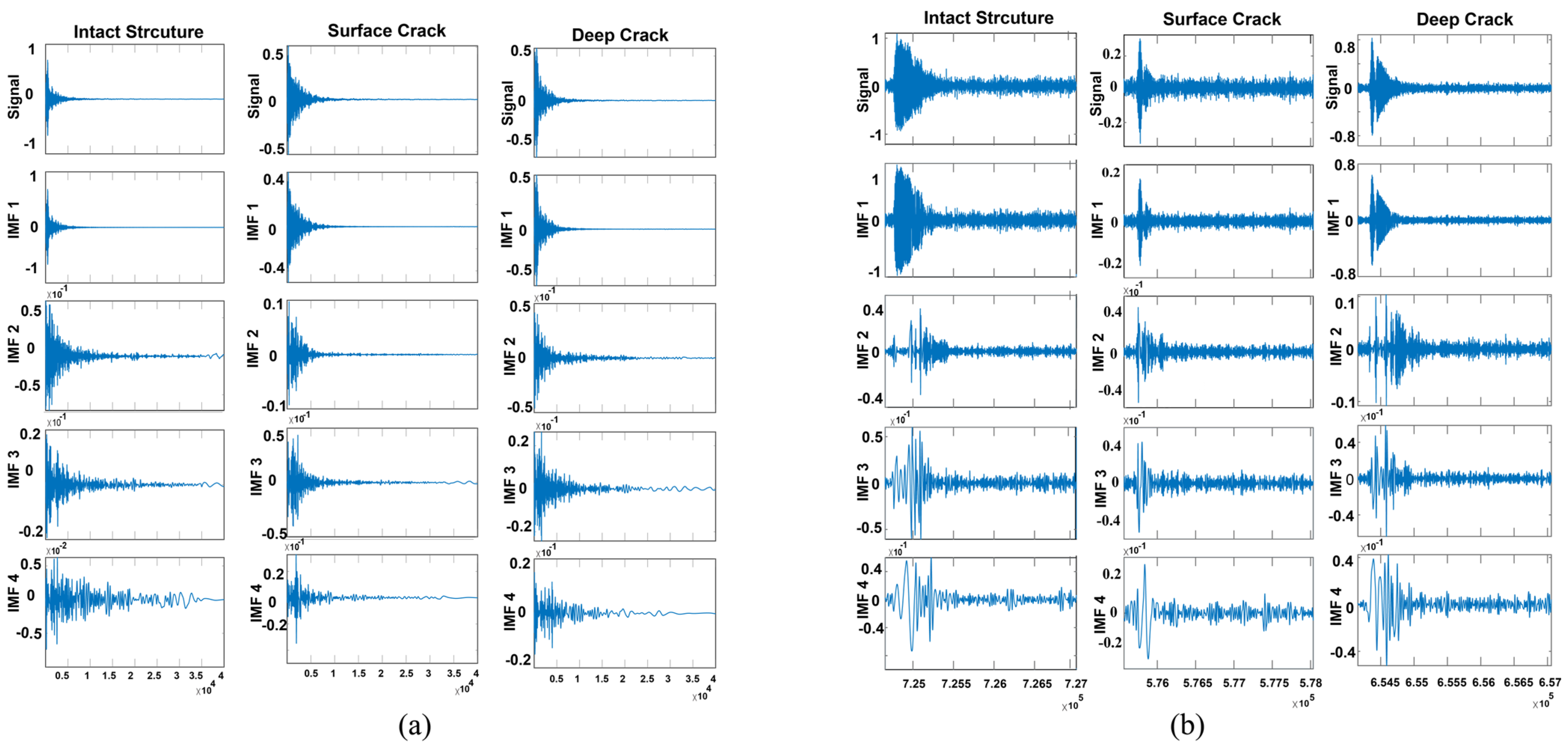
HHT is also applied to the signal, displaying the first four IMFs in Figure 8 to make a comparison between the simulation and experiment at points upstream of the crack. The first intrinsic mode function (IMF1) is typically extracted straight from the original signal, often appearing nearly identical to the original waveform, with negligible discrepancies. In contrast, IMF2, IMF3, and IMF4 tend to display more pronounced differences from the original signal. For example, considerable deviation in IMF2 is found in the simulations presented in Figure 8a, where disruptions such as the lack of signal preceding the crack and inconsistencies following it are noticeable. Similarly, Figure 8b illustrate the disappearance of the signal over both surface-level and deep cracks, as evidenced by the signal and IMF1 observations.
In Figure 9a,c, where measurements are taken after the surface and deep cracks, the frequency is more dispersed around the center frequency compared to the intact structure in the frequency domain. Similarly, the results in Figure 10 suggest the same trend for the experimental data. Furthermore, as can be seen in Figure 9b, there is a noticeable reduction in the detected signal within the damaged structure, which changes according to the depth of the affected area. In contrast, the short pulse moves across the undamaged structure with ease. In Figure 11, the application of HHT to the first four IMFs at points downstream of the crack is depicted, facilitating a comparison between the simulation and experiment.
While the presented simulations are in qualitative agreement with the experiments, there are still discernible differences which can be attributed to various factors. For example, the measurement may be impacted by background noise during the testing and imperfections in the test prototype material, as well as the actual acoustic impedance of the testing that are not considered in the numerical simulations. Furthermore, there is a notable discrepancy in the duration covered by the experimental data and the simulation, with the former encompassing one second and the latter just 0.01 s. Additionally, while the simulation specifically measures the change in velocity magnitude of the blade, the physical experiment primarily measures the out-of-plane velocity change at each point. As indicated in Figure 2, the experimental data at 200 kHz reveal different wave modes, including both in-plane and out-of-plane vibrations. Despite these variances, the comparative analysis of IMFs convincingly demonstrates their potential utility in identifying structural damage within WTBs.

5. Conclusions

In this study, a preliminary exploration of a non-invasive detection of cracks in a WTB was conducted, using a multidisciplinary methodology that combined experimental and simulation techniques. This study employed both numerical analysis and empirical testing, which involved creating brief pulse waves and subsequently using HHT for the analysis of IMFs. Deploying the HHT on the gathered data was crucial for accentuating the variances between intact and compromised structures. From the findings presented, it was evident that in the event of damage, the data patterns collected near the affected area display significant deviations when contrasted with those from an undamaged structure. Frequency domain analysis, exhibited by the use of FFT and the Hilbert spectrum, were critical in order to enhance the capability of recognizing variations in the infrastructure and evaluate the degree of damage included in the proposed WTB. The proposed analysis was successfully able to implement a reliable foundation for non-distractive inspection that could be applied to a variety of structures due to its capability of being applied at a distance up to 200 m away from the inspected structure [38]. Monitoring WTBs with LDV allows for faster and more efficient assessment, overcoming accessibility issues. The synergistic combination of experimental methods, computational simulations, and advanced signal processing techniques enables a nuanced and detailed grasp of composite structural responses. However, the real-world application of short pulse propagation in actual WTBs and the execution of LDV measurements in the field introduce certain obstacles that must be overcome to refine this methodology. It is essential to further explore the characteristics of wave propagation on a broader scale, considering the potential influences of environmental factors and other variables. The current research contributes to the structural inspection of wind turbines, which represents an important task during their operation and maintenance. The main results of this study include the following:
  • The investigation into the IMFs, namely the first, second, third, and forth IMF, showed great potential as a reliable marker for identifying signal irregularities.
  • IMF1 has the highest correlation factor.
  • IMF2 can serve as a viable indicator of short pulses when the signal is noisy.
  • In the damaged structure, the FFT exhibits variations and higher-frequency components compared to the intact structure.
  • Increasing the crack depth distorts the signal more in the time domain.
  • The similarities and differences between simulation and experiment were analyzed, which could be helpful for future structural inspection studies of WTBs.

Author Contributions

Conceptualization, N.K.S., R.J. and C.S.; data curation, A.Z. and F.A.; formal analysis, A.Z., F.A., C.E. and C.S.; funding acquisition, C.S.; methodology, A.Z., F.A. and C.E.; supervision, N.K.S., R.J. and C.S.; writing—original draft, A.Z. and F.A.; writing—review and editing, A.Z., F.A., C.E., N.K.S., R.J. and C.S. All authors have read and agreed to the published version of the manuscript.

Funding

This work was supported by the National Science Foundation under Grant No. CMMI-2137749 and the New Jersey Economic Development Authority (NJEDA).

Data Availability Statement

The original contributions presented in the study are included in the article, further inquiries can be directed to the corresponding authors.

Conflicts of Interest

The authors declare no conflicts of interest.

References

  1. Paraschiv, L.S.; Paraschiv, S. Contribution of Renewable Energy (Hydro, Wind, Solar and Biomass) to Decarbonization and Transformation of the Electricity Generation Sector for Sustainable Development. Energy Rep. 2023, 9, 535–544. [Google Scholar] [CrossRef]
  2. Elgendi, M.; AlMallahi, M.; Abdelkhalig, A.; Selim, M.Y.E. A Review of Wind Turbines in Complex Terrain. Int. J. Thermofluids 2023, 17, 100289. [Google Scholar] [CrossRef]
  3. Dimitrova, M.; Aminzadeh, A.; Meiabadi, M.S.; Sattarpanah Karganroudi, S.; Taheri, H.; Ibrahim, H. A Survey on Non-Destructive Smart Inspection of Wind Turbine Blades Based on Industry 4.0 Strategy. Appl. Mech. 2022, 3, 1299–1326. [Google Scholar] [CrossRef]
  4. Algolfat, A.; Wang, W.; Albarbar, A. The Sensitivity of 5MW Wind Turbine Blade Sections to the Existence of Damage. Energies 2023, 16, 1367. [Google Scholar] [CrossRef]
  5. Leon, M., Jr. Recycling of Wind Turbine Blades: Recent Developments. Curr. Opin. Green Sustain. Chem. 2023, 39, 100746. [Google Scholar] [CrossRef]
  6. Gao, R.; Yang, J.; Yang, H.; Wang, X. Wind-Tunnel Experimental Study on Aeroelastic Response of Flexible Wind Turbine Blades under Different Wind Conditions. Renew. Energy 2023, 219, 119539. [Google Scholar] [CrossRef]
  7. Sun, S.; Wang, T.; Yang, H.; Chu, F. Condition Monitoring of Wind Turbine Blades Based on Self-Supervised Health Representation Learning: A Conducive Technique to Effective and Reliable Utilization of Wind Energy. Appl. Energy 2022, 313, 118882. [Google Scholar] [CrossRef]
  8. Liu, S.; Ren, S.; Jiang, H. Predictive Maintenance of Wind Turbines Based on Digital Twin Technology. Energy Rep. 2023, 9, 1344–1352. [Google Scholar] [CrossRef]
  9. Kaewniam, P.; Cao, M.; Alkayem, N.F.; Li, D.; Manoach, E. Recent Advances in Damage Detection of Wind Turbine Blades: A State-of-the-Art Review. Renew. Sustain. Energy Rev. 2022, 167, 112723. [Google Scholar] [CrossRef]
  10. Reddy, A.; Indragandhi, V.; Ravi, L.; Subramaniyaswamy, V. Detection of Cracks and Damage in Wind Turbine Blades Using Artificial Intelligence-Based Image Analytics. Measurement 2019, 147, 106823. [Google Scholar] [CrossRef]
  11. Denhof, D.; Staar, B.; Lütjen, M.; Freitag, M. Automatic Optical Surface Inspection of Wind Turbine Rotor Blades Using Convolutional Neural Networks. Procedia CIRP 2019, 81, 1166–1170. [Google Scholar] [CrossRef]
  12. He, Y.; Li, M.; Meng, Z.; Chen, S.; Huang, S.; Hu, Y.; Zou, X. An Overview of Acoustic Emission Inspection and Monitoring Technology in the Key Components of Renewable Energy Systems. Mech. Syst. Signal Process. 2021, 148, 107146. [Google Scholar] [CrossRef]
  13. Niezrecki, C.; Poozesh, P.; Aizawa, K.; Heilmann, G. Wind Turbine Blade Health Monitoring Using Acoustic Beamforming Techniques. J. Acoust. Soc. Am. 2014, 135, 2392–2393. [Google Scholar] [CrossRef]
  14. Groth, E.B.; Clarke, T.G.R.; Schumacher da Silva, G.; Iturrioz, I.; Lacidogna, G. The Elastic Wave Propagation in Rectangular Waveguide Structure: Determination of Dispersion Curves and Their Application in Nondestructive Techniques. Appl. Sci. 2020, 10, 4401. [Google Scholar] [CrossRef]
  15. Li, Y.; Dieussaert, E.; Baets, R. Miniaturization of Laser Doppler Vibrometers—A Review. Sensors 2022, 22, 4735. [Google Scholar] [CrossRef] [PubMed]
  16. Dilek, A.U.; Oguz, A.D.; Satis, F.; Gokdel, Y.D.; Ozbek, M. Condition Monitoring of Wind Turbine Blades and Tower via an Automated Laser Scanning System. Eng. Struct. 2019, 189, 25–34. [Google Scholar] [CrossRef]
  17. Zieger, T.; Nagel, S.; Lutzmann, P.; Kaufmann, I.; Ritter, J.; Ummenhofer, T.; Knödel, P.; Fischer, P. Simultaneous Identification of Wind Turbine Vibrations by Using Seismic Data, Elastic Modeling and Laser Doppler Vibrometry. Wind Energy 2020, 23, 1145–1153. [Google Scholar] [CrossRef]
  18. Vuye, C.; Vanlanduit, S.; Presezniak, F.; Steenackers, G.; Guillaume, P. Optical Measurement of the Dynamic Strain Field of a Fan Blade Using a 3D Scanning Vibrometer. Opt. Lasers Eng. 2011, 49, 988–997. [Google Scholar] [CrossRef]
  19. Yu, L.; Tian, Z. Lamb Wave Structural Health Monitoring Using a Hybrid PZT-Laser Vibrometer Approach. Struct. Health Monit. 2013, 12, 469–483. [Google Scholar] [CrossRef]
  20. Allen, M.S.; Sracic, M.W. A New Method for Processing Impact Excited Continuous-Scan Laser Doppler Vibrometer Measurements. Mech. Syst. Signal Process. 2010, 24, 721–735. [Google Scholar] [CrossRef]
  21. Chen, Y.; Griffith, D.T. Experimental and Numerical Full-Field Displacement and Strain Characterization of Wind Turbine Blade Using a 3D Scanning Laser Doppler Vibrometer. Opt. Laser Technol. 2023, 158, 108869. [Google Scholar] [CrossRef]
  22. Chen, Y.; Escalera Mendoza, A.S.; Griffith, D.T. Experimental Dynamic Characterization of Both Surfaces of Structures Using 3D Scanning Laser Doppler Vibrometer. Exp. Tech. 2023, 47, 989–1006. [Google Scholar] [CrossRef]
  23. Liu, J.; Wang, X.; Yuan, S.; Li, G. On Hilbert-Huang Transform Approach for Structural Health Monitoring. J. Intell. Mater. Syst. Struct. 2006, 17, 721–728. [Google Scholar] [CrossRef]
  24. Dehina, W.; Boumehraz, M.; Kratz, F. Detectability of Rotor Failure for Induction Motors through Stator Current Based on Advanced Signal Processing Approaches. Int. J. Dyn. Control 2021, 9, 1381–1395. [Google Scholar] [CrossRef]
  25. Zhang, Q.; Wang, Y.; Sun, Y.; Gao, L.; Yue, Y. Hilbert–Huang Transform Based Method for Monitoring the Crack of Concrete Arch by Using FBG Sensors. Optik 2016, 127, 3417–3422. [Google Scholar] [CrossRef]
  26. Al-hababi, T.; Alkayem, N.F.; Asteris, P.G.; Wang, J.; Hu, S.; Cao, M. Time-Frequency Domain Methods for the Identification of Breathing Cracks in Beam-like Structures. Tribol. Int. 2023, 180, 108202. [Google Scholar] [CrossRef]
  27. Chen, B.; Zhao, S.; Li, P. Application of Hilbert-Huang Transform in Structural Health Monitoring: A State-of-the-Art Review. Math. Probl. Eng. 2014, 2014, 317954. [Google Scholar] [CrossRef]
  28. Hamdi, S.E.; Le Duff, A.; Simon, L.; Plantier, G.; Sourice, A.; Feuilloy, M. Acoustic Emission Pattern Recognition Approach Based on Hilbert–Huang Transform for Structural Health Monitoring in Polymer-Composite Materials. Appl. Acoust. 2013, 74, 746–757. [Google Scholar] [CrossRef]
  29. Xiaoming, N.; Jian, Z.; Xingwu, L. Application of Hilbert–Huang Transform to Laser Doppler Velocimeter. Opt. Laser Technol. 2012, 44, 2197–2201. [Google Scholar] [CrossRef]
  30. Teng, F.; Wei, J.; Lv, S.; Geng, X.; Peng, C.; Zhang, L.; Ju, Z.; Jia, L.; Jiang, M. Damage Localization in Carbon Fiber Composite Plate Combining Ultrasonic Guided Wave Instantaneous Energy Characteristics and Probabilistic Imaging Method. Measurement 2023, 221, 113443. [Google Scholar] [CrossRef]
  31. Kumar, R.; Sharma, L.; Chhibber, R.; Dixit, A.; Singhal, R. Environmental Degradation of Glass Fiber-Reinforced Nanocomposites with Self-Healing Reinforcement in Polymer Matrix for Wind Turbine Blade Application. Trans. Indian Inst. Met. 2021, 74, 3119–3133. [Google Scholar] [CrossRef]
  32. Amano, R.S.; Lewinski, G.; Shen, R. Imprinted Glass Fiber-Reinforced Polymer Vascular Networks for Creating Self-Healing Wind Turbine Blades. J. Energy Resour. Technol. 2022, 144, 062107. [Google Scholar] [CrossRef]
  33. Cousins, D.S.; Suzuki, Y.; Murray, R.E.; Samaniuk, J.R.; Stebner, A.P. Recycling Glass Fiber Thermoplastic Composites from Wind Turbine Blades. J. Clean. Prod. 2019, 209, 1252–1263. [Google Scholar] [CrossRef]
  34. Rawat, P.; Singh, N.K.; Singh, K.K.; Agrhari, N. Influence of Oblique Impact on Glass Fiber-Reinforced Polymer Composites: A Numerical Approach. In Trends in Materials Engineering; Springer Nature: Singapore, 2019; pp. 77–86. [Google Scholar]
  35. Kuppusamy, R.R.P.; Rout, S.; Kumar, K. Advanced Manufacturing Techniques for Composite Structures Used in Aerospace Industries. In Modern Manufacturing Processes; Elsevier: Amsterdam, The Netherlands, 2020; pp. 3–12. [Google Scholar]
  36. Xin, H.; Liu, Y.; Mosallam, A.S.; He, J.; Du, A. Evaluation on Material Behaviors of Pultruded Glass Fiber Reinforced Polymer (GFRP) Laminates. Compos. Struct. 2017, 182, 283–300. [Google Scholar] [CrossRef]
  37. He, Y.; Chen, H.; Liu, D.; Zhang, L. A Framework of Structural Damage Detection for Civil Structures Using Fast Fourier Transform and Deep Convolutional Neural Networks. Appl. Sci. 2021, 11, 9345. [Google Scholar] [CrossRef]
  38. Yang, S.; Allen, M.S. Output-Only Modal Analysis Using Continuous-Scan Laser Doppler Vibrometry and Application to a 20 KW Wind Turbine. Mech. Syst. Signal Process. 2012, 31, 228–245. [Google Scholar] [CrossRef]
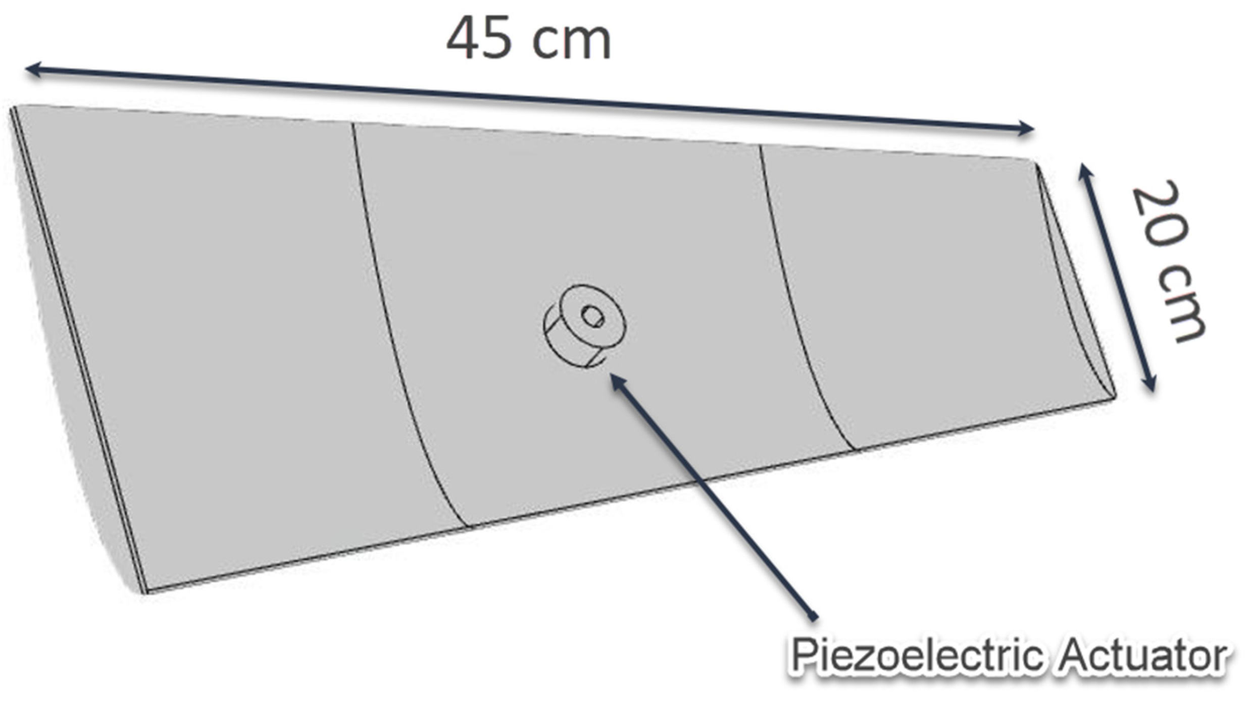
Figure 1. Schematic of the wind turbine blade with piezoelectric actuator.
Energies 17 02165 g001
Figure 2. (a) Frequency–wave vector dispersion in the structure; (b) out-of-plane vibration in the structure; (c) in-plane vibration in the structure.
Energies 17 02165 g002
Figure 3. Measurement setup and the process of measurement.
Energies 17 02165 g003
Figure 4. (a) Time domain, FFT, and Hilbert spectrum of propagation of short pulses in the piezoelectric actuator; (b) raw signal containing four short pulses; (c) zoom-in plot showing the profile of one short pulse.
Energies 17 02165 g004
Figure 5. Comparison of IMF 1, 2, 3, and 4 in a noisy signal.
Energies 17 02165 g005
Figure 6. Comparison of intact and damaged structures with data taken before the crack: (a) damaged wind turbine blade; (b) normalized velocity of the cut point taken from the time-domain simulation in COMSOL Multiphysics; (c) the corresponding FFT results of the time-domain signals.
Energies 17 02165 g006
Figure 7. Experimental results where the measurements are taken at a point upstream of the crack. (a) Time-domain signals; (b) FFT of the experimentally obtained signals; (c) Hilbert spectrum in the experiment.
Energies 17 02165 g007
Figure 8. Comparison of IMFs from HHT at a point upstream of the crack: (a) simulation; (b) experiment.
Energies 17 02165 g008
Figure 9. Comparison of intact and damaged structures with data taken after the crack: (a) damaged wind turbine blade; (b) normalized velocity of the cut point taken from the time-domain simulation in COMSOL Multiphysics; (c) the corresponding FFT results of the time-domain signals.
Energies 17 02165 g009
Figure 10. Experimental results where the measurements are taken at a point downstream of the crack. (a) Time-domain signals; (b) FFT of the experimentally obtained signals; (c) Hilbert spectrum in the experiment.
Energies 17 02165 g010
Figure 11. Comparison of IMFs from HHT at a point downstream of the crack. (a) HHT of the signals obtained from time-domain simulation; (b) HHT of the signals obtained from experiment.
Energies 17 02165 g011
Table 1. Correlation coefficient of the first four IMFs with the original signal.
IMF1234
Correlation Coefficient0.99480.05380.00210.003
Disclaimer/Publisher’s Note: The statements, opinions and data contained in all publications are solely those of the individual author(s) and contributor(s) and not of MDPI and/or the editor(s). MDPI and/or the editor(s) disclaim responsibility for any injury to people or property resulting from any ideas, methods, instructions or products referred to in the content.