Article

Hybrid Deloading Control Strategy in MMC-Based Wind Energy Conversion Systems for Enhanced Frequency Regulation

Department of Electrical and Computer Engineering, Rowan University, Glassboro, NJ 08028, USA
*
Author to whom correspondence should be addressed.
Energies 2024, 17(5), 1253; https://doi.org/10.3390/en17051253
Submission received: 1 February 2024 / Revised: 29 February 2024 / Accepted: 4 March 2024 / Published: 6 March 2024
(This article belongs to the Special Issue Latest Developments in Offshore Wind Technologies)

Abstract

:
The growing integration of renewable energy sources, especially offshore wind (OSW), is introducing frequency stability challenges to electric power grids. This paper presents a novel hybrid deloading control strategy that enables modular multilevel converter (MMC)-based wind energy conversion systems (WECSs) to actively contribute to grid frequency regulation. This research investigates a permanent-magnet synchronous generator (PMSG)-based direct-drive configuration, sourced from the International Energy Agency’s (IEA’s) 15 MW reference turbine model. Specifically, phase-locked loop (PLL)-free grid-forming (GFM) control is employed via the grid-side converter (GSC), and DC-link voltage control is realized through the machine-side converter (MSC), both of which boost the energy support for the integrated AC grid’s frequency stability. This control strategy combines the benefits of over-speeding and pitch control modes, facilitating smooth transitions between different modes based on real-time wind speed measurements. In addition, the practical challenges of MMCs, such as circulating currents and capacitor voltage imbalances, are addressed. Numerical simulations under varying wind speeds and loading conditions validate the enhanced frequency regulation capability of the proposed approach.

1. Introduction

Global warming and air pollution represent two paramount global challenges. Concurrently, the escalating demand for electricity to satisfy wintertime heating and summertime cooling needs due to increasingly frequent extreme weather events, along with widespread electrification across the transportation and building sectors, is introducing additional stress to the power grid. Renewable energy sources, particularly solar and wind, emerge as viable and environmentally sustainable solutions for addressing these pressing issues. With its ample offshore wind resources, the United States is well positioned to substantially augment its renewable energy capacity. The federal government has set an ambitious goal of deploying 30 gigawatts (GWs) of offshore wind (OSW) by 2030 [1], which aligns with individual states’ objectives, such as New Jersey’s goal of achieving 3.5 GWs by 2030 and 11 GWs by 2040 [2]. Harnessing the full potential of OSW holds the promise of diversifying the nation’s clean energy portfolio and expediting the transition towards carbon-neutral electric power systems. However, realizing this vision necessitates advancements in both wind generation and control technologies.
For efficient generation and transmission of high-voltage and high-power energy, permanent-magnet synchronous generators (PMSGs) have become a compelling option for offshore wind energy conversion systems (WECSs) due to their high power density, efficiency, and reliability [3]. PMSGs have been widely adopted by market-leading offshore wind turbine manufacturers such as Vestas, Siemens Energy, and General Electric into their state-of-the-art product lines. The design of PMSGs eliminates the need for external excitation, which is advantageous for black-start operations. Furthermore, the absence of gearboxes in the direct-drive configuration improves the overall system reliability. In conjunction with PMSGs, power electronic converters (PECs) are another integral component of WECSs. PECs for WECSs generally employ a cascaded and paralleled structure that consists of multiple power modules. Notably, among the prevalent topologies [4], modular multilevel converters (MMCs) [5,6] have shown great promise. Initially developed for high-voltage direct-current (HVDC) transmission systems, MMCs offer a scalable and transformer-less structure. They can withstand high voltage levels and greatly reduce the average switching frequency of PECs without compromising power quality.
The output characteristics of WECSs are highly influenced by control schemes implemented in PECs. Conventionally, WECSs utilize maximum power point tracking (MPPT) schemes [7] to optimize economic returns. The PECs function as grid-following (GFL) current sources that rely on a stiff external grid, while the kinetic energy in wind turbines and generator rotating masses does not directly contribute to grid inertia due to the decoupling of their rotating speed from the grid frequency. Therefore, traditional WECSs are generally not designed to provide essential grid services such as inertial and frequency response. However, as fossil-fuel-fired synchronous generators (SGs) are gradually phased out and replaced by clean and/or renewable energy resources, the electric grid is expected to experience a decline in both inertia and damping, leading to a more pronounced frequency nadir and rate of change in frequency.
Under this context, there is a growing interest in grid-forming (GFM) control [8] for its potential to improve grid stability and reliability. GFM control allows PECs to operate as voltage sources, thereby emulating SG’s functionalities such as grid stabilization, self-synchronization, and frequency/voltage regulation. GFM control requires a stable source of energy, with traditional GFM strategies [9,10] often assuming a constant DC-link voltage, which is not suitable for WECSs due to the intermittent nature of the wind energy source. In [11], energy storage systems (ESSs) were integrated to regulate the DC-link voltage, enabling WECSs to operate continuously in MPPT mode while the grid-side converter (GSC) functions as a GFM converter. However, this configuration limits the grid support capability to the ESS’s capacity and necessitates an oversized GSC. Alternatively, the ESS could be installed on the AC side. With the ESS managing the virtual synchronous generator (VSG) control [12], the GFL control could be applied to the machine-side converter (MSC) of the WECS without further modifications. Nevertheless, islanded operations remain a challenge for such GFL-controlled WECSs. Inclusion of ESSs can also result in higher initial investments, increased maintenance costs, and potential reliability issues, all of which warrant careful evaluation.
To this end, GFM control schemes without ESSs have been explored for WECSs [13,14]. The authors of [15] introduced a supplementary controller into an MPPT-based MSC. This strategy capitalized on the rotational energy stored in wind turbine rotors to provide additional inertial and primary frequency support. Another method was presented in [16], where a GSC provided inertial response and damping by correlating the DC-link voltage with the grid frequency under a droop mechanism. However, these methods can only provide short-term frequency support and are vulnerable to secondary frequency drop issues during rotor speed recovery [17]. Moreover, GSCs depend heavily on the external grid voltage for DC-link voltage regulation. Reference [18] presented a GFM control with enhanced torsional vibration damping. It utilized a MSC to regulate the DC-link voltage, allowing the PMSG and the MSC to behave as a voltage source for the GSC. While this implementation promotes grid support rather than dependence, it requires a phase-locked loop (PLL) for grid frequency measurement, which could induce instability under weak grid conditions [19]. For enhanced long-term frequency support, deloading strategies offer another avenue. By intentionally operating wind turbines at suboptimal power points, reserved power could be ramped up for grid stabilization when needed [20]. Deloading could be achieved through two primary techniques: pitch angle control [21] and over-speeding control [22]. The primary function of pitch control is to down-regulate power outputs. However, frequent activation of pitch control could wear mechanical drives. In addition, its effectiveness is restricted by a relatively slow dynamic response owing to a large mechanical time constant. On the other hand, while over-speeding control has a faster response, it has a limited control spectrum, especially when the rotor approaches the maximum allowable speed. Given the pros and cons of both methods, hybrid control mechanisms [20,23] are designed to improve the power regulation flexibility of wind turbines and maximize the efficiency and reliability of WECSs. Furthermore, it is crucial to consider the practicalities of implementing such control methods in real-world applications. Much of the prior research has predominantly validated their approaches on traditional two-level PECs. However, these converters fall short of meeting the high-power and high-voltage requirements of WECSs. To accurately represent and implement GFM control in offshore WECSs, it is essential to adopt MMCs, as they more closely align with the practical realities and demands of these systems.
In this work, a novel GFM control strategy is proposed for integrating offshore WECSs into the grid with enhanced stability and reliability. The major contributions of this work include:
(1)
A hybrid deloading control strategy is proposed for implementing GFM control of offshore WECSs to pursue long-term frequency support to the grid. The proposed strategy could operate the WECSs across a wide range of wind speeds, while ensuring a smooth transition between over-speeding and pitch control modes based on wind speed measurements.
(2)
The MSC is controlled to stabilize the DC-link voltage with improved grid support functionality, and the GSC based on the VSG concept efficiently aids in system frequency regulation and inertial response without requiring a PLL.
(3)
The performance of the proposed control strategy is evaluated on an MMC-based WECS, reflecting the state of the art in offshore wind energy generation technologies.
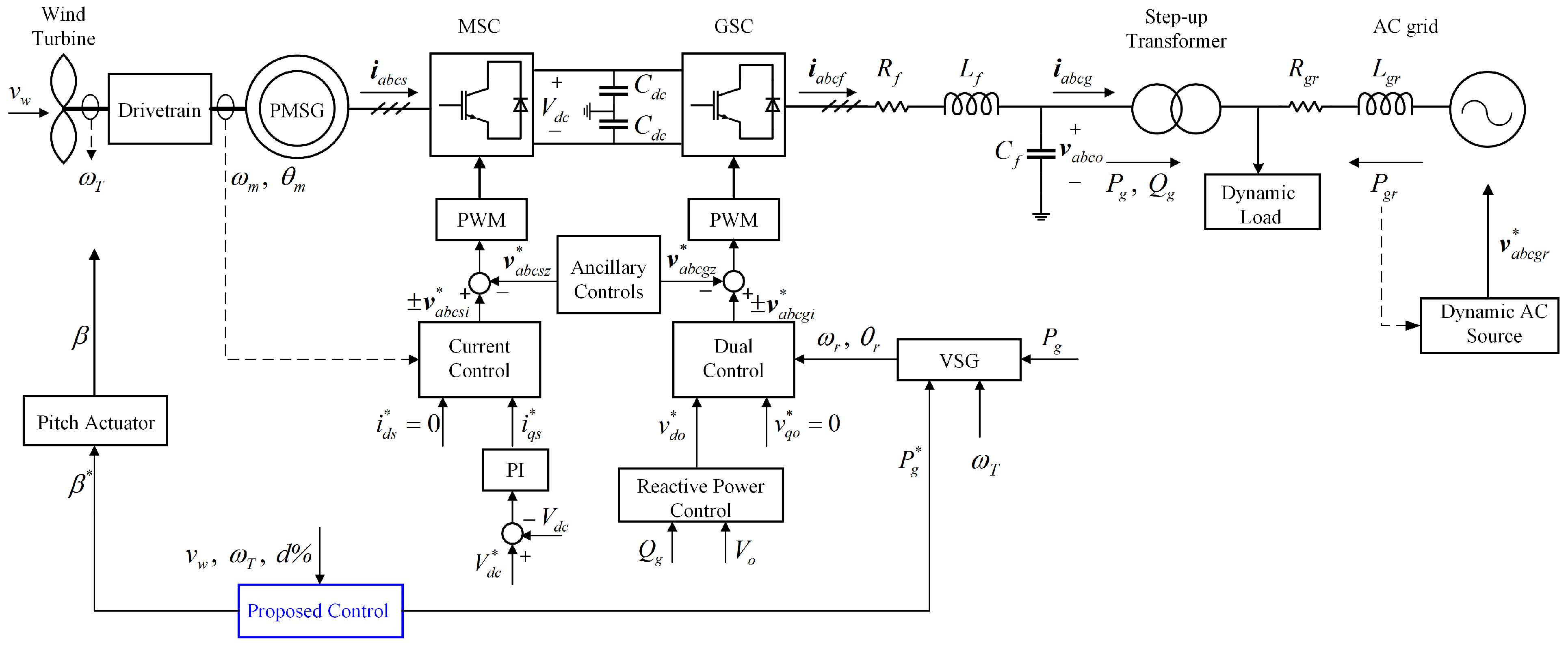
The remainder of this paper is structured as follows: Section 2 presents the detailed modeling of a WECS connected to an AC grid, with a focus on the lower-level controls of the MMC-based MSC and GSC. Section 3 presents the proposed hybrid deloading GFM control strategy. In Section 4, numerical simulations are conducted to evaluate the effectiveness of the proposed approach, followed by the identification of potential avenues for future research. Finally, Section 5 provides the conclusions.

2. WECS Modeling

Figure 1 depicts the overall structure of the MMC-based WECS connected to an external AC grid, with the proposed control module highlighted in blue. The wind turbine is connected to the PMSG via the drivetrain. The PMSG feeds the electrical power to the AC grid through a back-to-back converter. This back-to-back converter is composed of two MMCs: the MSC and the GSC. Two series-connected capacitors constitute the DC link. While the LC filter at the GSC output terminal is optional, it becomes beneficial when the MMCs have a limited number of voltage levels. The LC filter improves power quality by filtering out switching harmonics. In this work, the phase-shifted carrier (PSC) pulse width modulation (PWM) technique is employed due to its advantages, such as evenly distributed pulses and reduced DC-link current ripples [24]. The modeling of the main components of the WECS under consideration and the AC grid, as well as the main control modules associated with the MSC and the GSC except the proposed control scheme, are elaborated in this section.

2.1. Wind Turbine Model

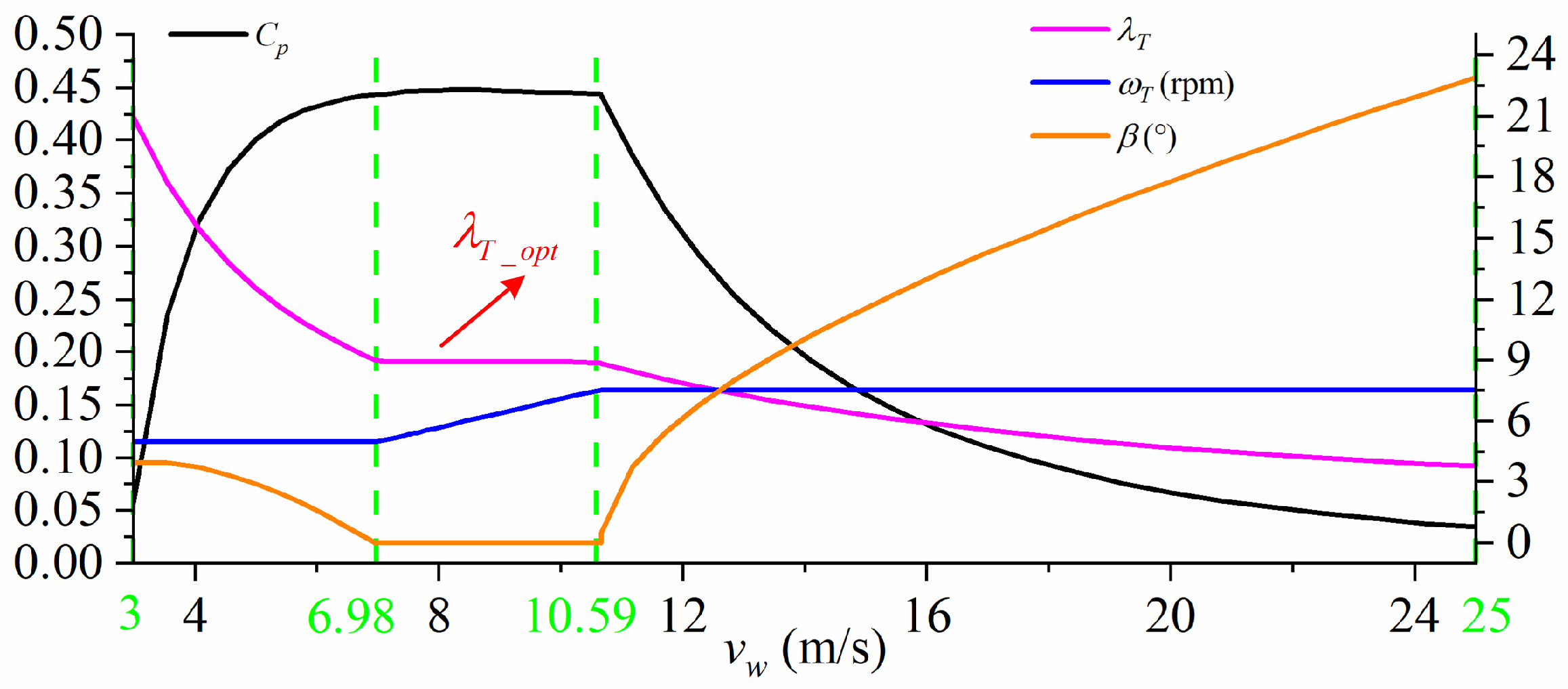
2.1.1. Wind Turbine Aerodynamics

Wind turbines convert the kinetic energy of wind into mechanical power ( P T ) by the rotor blades:
P T = 1 2 ρ π R T 2 v w 3 C p ( λ T , β ) ,
where ρ is air density, R T is the rotor blade radius, v w is the wind speed, and C p is the power coefficient that indicates the turbine’s aerodynamic efficiency. C p is a function of the tip speed ratio (TSR) λ T and the blade pitch angle β . The TSR is defined as
λ T = ω T R T v w ,
where ω T is the rotor’s angular speed. C p can be mathematically expressed using various functions [25], and this study employs a polynomial function:
C p λ T , β = i = 0 4 j = 0 4 a i j λ T j β i ,
where coefficients a i j can be determined through curve fitting of turbine operational data. For β = 0 , C p achieves its maximum value C p m a x = C p λ T _ o p t , 0 at the optimal TSR ( λ T _ o p t ), allowing the wind turbine to maximize energy extraction:
P m p p t = ρ π R T 5 C p m a x 2 λ T _ o p t 3 ω T 3 = K o p t ω T 3 .
In this study, the International Energy Agency (IEA) 15 MW reference wind turbine [26] is utilized for WECS modeling. This turbine was chosen for its established role as an open benchmark to validate the applicability and/or cost-effectiveness of proposed solution methods in OSW. Its typical operating curves are displayed in Figure 2.
This turbine has four specific operational wind speed thresholds: a cut-in wind speed ( v w _ c i ) of 3 m/s, an intermediate wind speed v w _ i n t of 6.98 m/s, a rated wind speed ( v w _ r a t e d ) of 10.59 m/s, and a cut-out wind speed ( v w _ c o ) of 25 m/s. Its operation is, thus, divided into five zones: Zones 1, 1.5, 2, 3, and 4. Since Zone 1 ( v w < v w _ c i ) and Zone 4 ( v w v w _ c o ) are generally uninteresting for standard control purposes, they are excluded from Figure 2. The other zones are detailed as follows:
Zone 1.5 ( v w _ c i v w < v w _ i n t ): In this zone, the wind speeds are insufficient to enable the wind turbine to operate at λ T _ o p t . A minimum pitch angle constraint is enforced to maintain efficient operation, which results in positive blade pitch angles up to 4° at these lower wind speeds.
Zone 2 ( v w _ i n t v w < v w _ r a t e d ): The wind speeds are high enough in this operational zone, so the wind turbine enters MPPT mode with λ T _ o p t to maximize energy capture and efficiency.
Zone 3 ( v r a t e d v w < v w _ c o ): In this zone, the wind speeds exceed the rated value. To limit mechanical loads and prevent the PMSG from being overloaded, the turbine rotor speed and the PMSG power output are maintained at their rated values. This regulation is achieved by dynamically adjusting the pitch angle.

2.1.2. Drivetrain

The drivetrain transfers mechanical energy from the rotating wind turbine blades to the PMSG and can be represented as a one- or two-mass model [27]. The two-mass model is favored for grid integration studies because it can capture torsional dynamics, such as resonances or oscillations, between the wind turbine and PMSG rotors. The two-mass model for direct drive is described as:
J T ω ˙ T = τ T τ s h a f t K T ω T ,
J m ω ˙ m = τ s h a f t K m ω m τ e ,
τ s h a f t = K s θ + B s θ , ˙
θ ˙ = ω T ω m ,
where J T and J m are the moments of inertia for the wind turbine and PMSG, respectively. ω m denotes the mechanical angular speed of the PMSG rotor. τ T is the turbine aerodynamic torque, τ s h a f t is the torque on the coupled shaft, and τ e is the electromagnetic toque of the PMSG. K T and K m are the viscous friction coefficients, while K s and B s are the stiffness and damping coefficients of the coupled shaft, respectively.

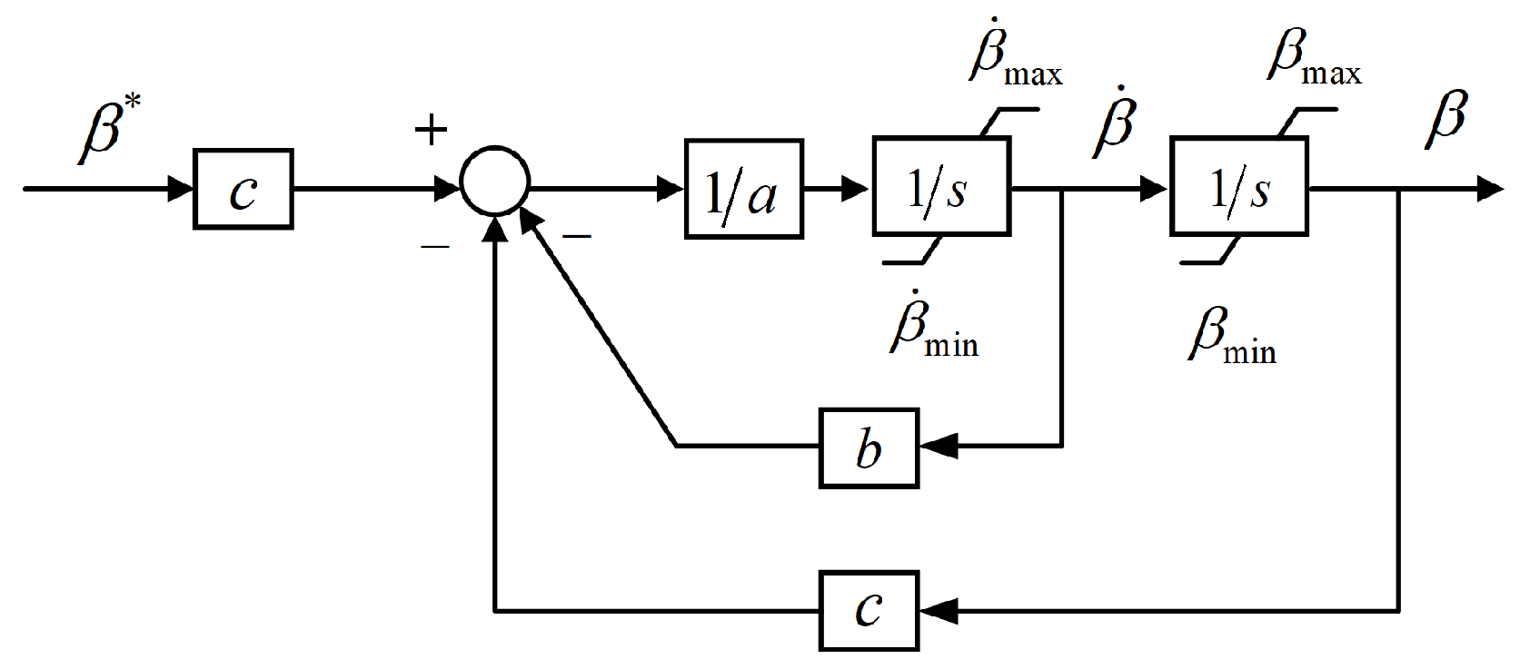
2.1.3. Pitch Actuator

The pitch angle of the wind turbine is adjustable for limiting turbine rotor speed and, thus, mechanical power outputs. Figure 3 illustrates a second-order pitch actuator model [28], acting on the pitch angle reference ( β * ), which is set by the proposed control module, with a, b, and c representing the model parameters. Also, the threshold values for both the pitch angle and the rate of its change are specified.

2.2. PMSG Model

A surface-mounted PMSG is considered in this work. Its stator current dynamics can be expressed in the synchronously rotating dq-axes rotor reference frame:
i ˙ d s ˙ = 1 L s ( v d s R s i d s + ω e L s i q s ) ,
i ˙ q s ˙ = 1 L s ( v q s R s i q s ω e L s i d s + ω e ψ f ) ,
τ e = 3 2 P p ψ f i q s ,
ω e = P p ω m ,
where i d s and i q s are the PMSG dq-axes stator currents, and v d s and v q s are its dq-axes stator voltages. R s and L s are the resistance of PMSG stator windings and the self-inductance, respectively. In addition, ψ f is the rotor flux linkage produced by the permanent magnet, ω e is the electrical angular speed of the PMSG rotor, and P p is the PMSG’s number of pole pairs.

2.3. MMC Model

2.3.1. General MMC Configuration

The generalized circuit configuration of a three-phase MMC is shown in Figure 4. The three-phase AC system (PMSG or AC grid) is connected to the midpoint of each phase leg. One leg consists of two arms, and each arm has a group of submodules (SMs), with an arm inductor ( L a r m ) and an arm resistor ( R a r m ) connected in series. The arm inductors are utilized to limit circulating currents among the phase legs and also DC-side short-circuit fault currents. For its simplicity, the two-level half bridge is chosen as the SM configuration in this work. Depending on the operating conditions, the individual voltages of the capacitors in the SMs can be inserted or bypassed by appropriately controlling the switches in the SMs to generate the desired output voltage waveforms.

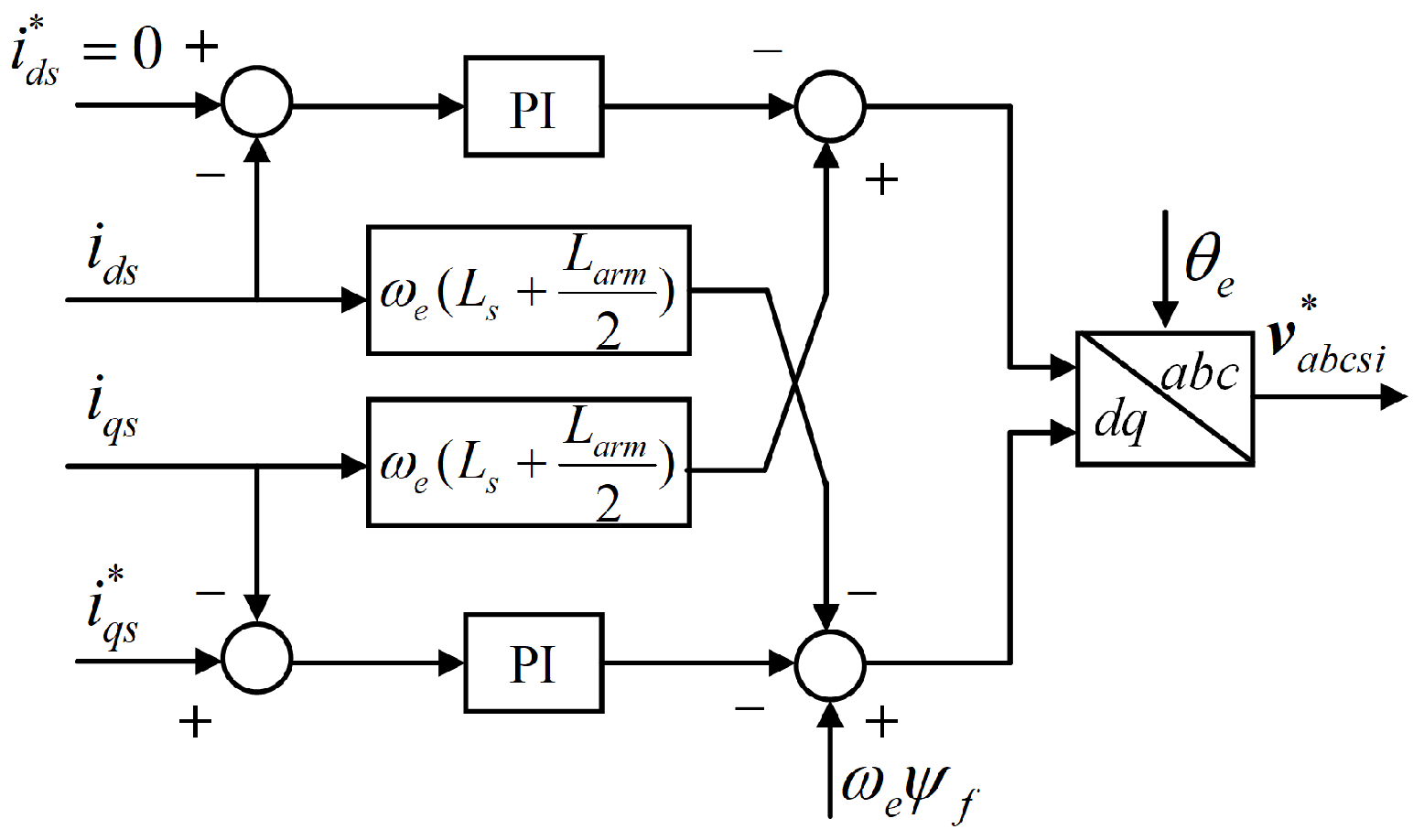
2.3.2. Machine-Side Control

The MSC is responsible for regulating the DC-link voltage ( V d c ) at its nominal value, achieved using the cascaded proportional–integral (PI) control, as depicted in Figure 1. The outer voltage control produces the q-axis current reference ( i q s * ) for the inner current control loop, with its detailed diagram shown in Figure 5, where the zero d-axis current (ZDC) control strategy [29] is applied. The decoupled control of the PMSG is analogous to a separately excited DC machine such that the electromagnetic torque ( τ e ) is directly controlled by the stator current. Moreover, the stator winding resistance R s is ignored in this control loop because it is generally negligible in high-power SGs. Lastly, the three-phase reference voltage component ( v a b c s i * ) is obtained through the inverse Park transform, based on the measured PMSG electrical rotor angle θ e .

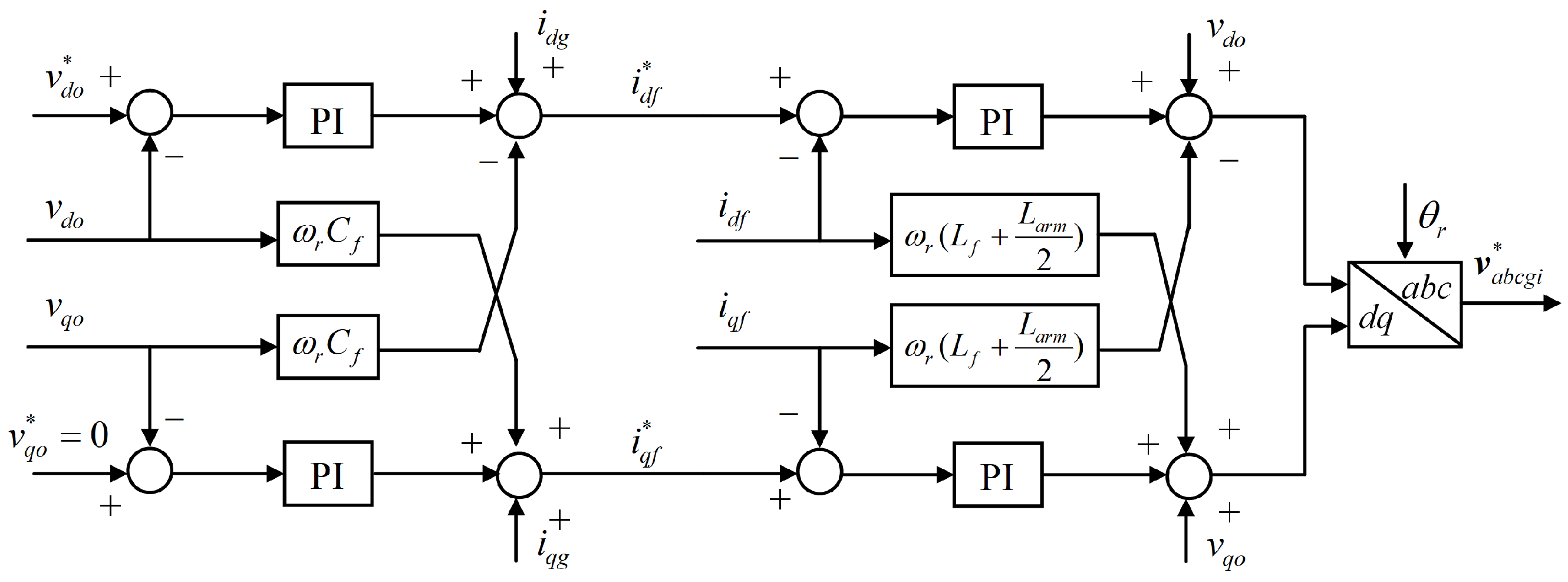
2.3.3. Grid-Side Control

The GSC primarily performs reactive power control and VSG-based grid-forming functionality. Figure 6 shows the reactive power control, which mimics the conventional SG exciter and controls the measured reactive power output ( Q g ) based on the output phase voltage magnitude V o calculated as 2 3 ( v a o 2 + v b o 2 + v c o 2 ) . V n and Q n are the nominal output phase voltage and reactive power, respectively. Q n is set as zero because additional reactive power support is unnecessary for nominal grid voltage. In addition, k v is a voltage droop coefficient, and the integral term k q s introduces virtual inertia. This reactive power control loop provides the d-axis voltage reference ( v d o * ) to the dual control module in Figure 1.
The dual control loop in the dq-axes reference frame is adopted due to its fast dynamic response and ability to limit grid fault currents. Similar to the MSC, it consists of an outer voltage control and an inner current control. In Figure 7, the outer voltage control loop tracks the voltage references ( v d o * and v q o * ) and generates the dq-axes current references ( i d f * and i q f * ) for the inner current control loop. Since the output voltage is aligned with the d axis of its reference frame, v q o * is set as zero. Furthermore, resistances are not considered within this dual control loop, given their negligible values. To generate the three-phase reference voltage component ( v a b c g i * ), the inverse Park transform is utilized. The phase angle θ r is provided by the VSG.
The VSG as shown in Figure 8 emulates the behavior of a conventional SG and implements active power control. It produces angular speed ω r and phase angle θ r . The speed governor block uses droop control for frequency regulation, where ω n denotes the nominal grid angular frequency and k f symbolizes the frequency droop coefficient. Unlike previous studies that adopted a static droop value, this paper introduces an adaptive k f to reflect the actual operating conditions more accurately. In effect, the kinetic energy stored in the wind turbine rotors varies with real-time operating conditions. This, in turn, affects the frequency regulation capability and the virtual inertia response. The instantaneously stored kinetic energy is 1 2 J T ω T 2 , and a factor is defined to relate the available kinetic energy to the maximum value:
κ : = ω T 2 ω T m i n 2 ω T m a x 2 ω T m i n 2 ,
where ω T m a x and ω T m i n correspond to the maximum and minimum allowable rotor speeds of the turbine, respectively. From this definition, this adaptive frequency droop coefficient can be formulated as:
k f = κ k f n ,
where k f n is the droop coefficient when the wind turbine operates at its rated rotor speed. In addition, an adaptive virtual inertia time constant is defined as:
H v i r = κ H v i r n ,
where H v i r n is the nominal virtual inertia time constant. The active power reference, denoted by P g * , is determined by the proposed control module. Furthermore, a low-pass filter (LPF) is used to model the dynamics of a prime mover. The difference between the filtered power reference and the measured active power output ( P g ) is initially normalized by the WECS’s nominal power rating S n . In the swing equation block, D p stands for the power damping coefficient. This VSG adopts the feed-forwarding power damping method outlined in [30], which eliminates the need for frequency measurement and has no influence on the VSG’s steady-state or inertial dynamics.

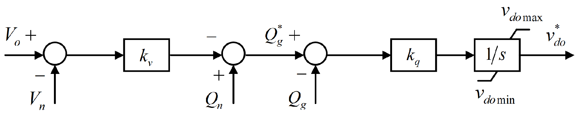
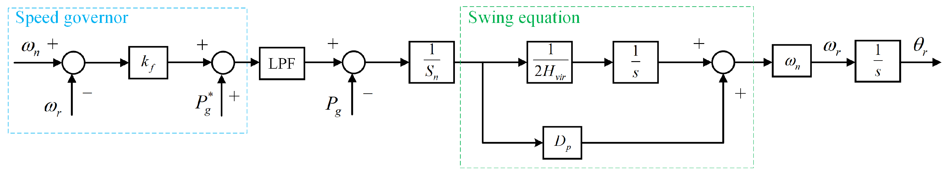
2.3.4. Ancillary Controls

The ancillary controls, namely SM capacitor voltage control (SCVC) and circulating current control (CCC), are common to both MMCs in the MSC and GSC. Since the SMs have floating capacitors, their voltages must be maintained at the nominal value ( V c * ). Therefore, SCVC is essential for ensuring MMC’s stable operation and improving power quality. SCVC has two control levels: arm voltage control, which balances the SMs within one arm, and leg voltage control (LVC), which regulates the average SM capacitor voltage across each phase leg to the nominal value. This work employs the aggregate model of the half-bridge MMC [31] to reduce simulation burdens. All SM capacitor voltages in one arm are assumed to be balanced via arm voltage control strategies such as [32], so only LVC is implemented in this paper.
Additionally, inevitable mismatches between the inserted voltage of each phase leg and the DC-link voltage give rise to circulating currents among the phase legs. These currents will result in increased current stresses and power losses in switching devices and voltage ripples in the SM capacitors, compromising the overall performance of MMCs. The circulating currents mainly include even-order harmonics of fundamental frequency and can be eliminated using multiple quasi-proportional-resonant (PR) controllers [32] in a stationary abc reference frame. The transfer function of a quasi-PR controller is as follows:
P R s = k p + h = 2 ,   4,6 2 ω c k r h s s 2 + 2 ω c s + ( h ω 0 ) ,
where k p represents the proportional coefficient, while k r h denotes the resonant coefficients. ω c is the cut-off frequency, and h ω 0 is the resonant frequency associated with the hth-order harmonic component to be eliminated. In this study, only the second-order harmonics are considered because they are the most dominant. The detailed diagram of ancillary controls is presented in Figure 9.
In the LVC block, the average SM capacitor voltage of each phase leg ( V c j ) is calculated as:
V c j = 1 2 N k = 1 N v c j u k + k = 1 N v c j l k ,
where v c j u k and v c j l k are the capacitor voltages of the kth SM in the upper (u) and lower (l) arms, respectively, of phase leg j, as shown in Figure 4. Moreover, the actual DC current component i x can be approximated using the arm currents:
i x = j = a , b , c i j u + j = a , b , c i j l 6
where i j u and i j l mean the currents flowing through the upper and lower arms, respectively, of phase leg j.
In the CCC block, the circulating current component i d i f f _ j for each phase is derived from its upper and lower arm currents and is suppressed to zero for elimination:
i d i f f _ j = i j u + i j l 2 .
Lastly, the outputs from both blocks are synthesized to modify the voltage references for the upper and lower arms in each phase leg as follows:
y j u * = v j i * v j z * V d c / 2 ,
y j l * = v j i * v j z * V d c / 2 ,
where v j i * refers to the reference voltage component of phase j generated by the inner current control loop in both MSC and GSC, while v j z * is the synthesized voltage of phase j by the ancillary controls. Furthermore, V d c is the measured DC-link voltage. The arm voltage references are then applied to the PSC–PWM blocks illustrated in Figure 1.

2.4. AC Grid Model

To analyze the frequency regulation capability of GFM control, it is essential to simulate an AC grid with inherent dynamics that could be effectively represented by an equivalent SG [18]. The AC grid in Figure 1 is then modeled as a controlled voltage source behind the grid impedance. The three-phase grid voltage reference ( v a b c g r * ) is generated from the speed droop control for the equivalent SG [33], with its simplified block diagram illustrated in Figure 10.
R d r o o p is the droop coefficient. A single-reheat tandem-compound steam turbine is modeled; T n and T d are its time constants. S g r n is the nominal power rating of the AC grid. P g r refers to the measured active power output of the AC grid, while P g r n ( p . u . ) represents the normalized value of the prescribed active power output at the system’s nominal angular frequency ( ω n ). P g r n ( p . u . ) is set as zero in this work. Moreover, V g n is the nominal peak phase voltage of the AC grid. The grid strength can be quantified by the short-circuit ratio (SCR), a metric directly correlated with grid impedance. A higher SCR value indicates a stiffer grid. For a given SCR, the grid reactance ( X g r ) and resistance ( R g r ) are specified as:
X g r = 3 V g n 2 2 S C R S g r n = ω n L g r ,
R g r = X g r σ X / R ,
where σ X / R is the quality factor of the AC grid impedance.

3. Proposed Hybrid Deloading Method

This section introduces the proposed hybrid deloading approach, devised to operate across a wide range of wind speeds. The wind turbines are made to deviate from the MPPT mode to preserve a certain amount of power margin (d). This results in the power output reference:
P d e l = 1 d P m p p t .
With reference to (1), the TSR required for this deviation ( λ T d e l ) is calculated from
C p λ T d e l , 0 = 1 d C p λ T o p t , 0 .
System operators have the flexibility to predetermine the power margin. Common choices include 1%, 5%, 10%, and 20%. This reserved power allows the WECS to actively participate in frequency regulation while effectively addressing secondary frequency drop issues. The P T versus ω T curves of the IEA 15 MW wind turbine under different wind speeds are presented in Figure 11, and d is chosen as 10% for illustration. The original MPPT curve with λ T _ o p t = 8.8775 is plotted based on (4). Using (23), the corresponding TSR for a 10% deloading at varying wind speeds is calculated as λ T _ d e l = 10.7584 , which indicates an over-speeding operation of the wind turbine.
At relatively lower wind speeds (e.g., v w = 0.7   p . u . ), there is sufficient headroom between point A 1 on the MPPT curve and the maximum allowable rotor speed ω T m a x . Hence, the corresponding point A 2 on the designed over-speeding curve is reachable. Nevertheless, as Figure 11 suggests, this headroom diminishes with wind speed increase. When wind speeds are at, say v w = 0.9   p . u . , the point B 2 on the deloading curve is already beyond ω T m a x , rendering the over-speeding operation itself infeasible to achieve 10% deloading at this wind speed. By clamping the rotor speed to ω T m a x , there is an upper bound ( v w _ h ) for wind speeds beyond which pitch control should further be applied to achieve the desired 10% deloading. This boundary value can be derived using the system parameters in [26]:
v w _ h = ω T m a x R T λ T _ d e l 8.83   m / s .
To minimize pitch control activation while retaining adequate reserve power, a new deloading (pitch-controlled) power reference curve is designed for wind speeds that fall between v w _ h and v w _ r a t e d . The required pitch angle ( β d e l ) for each wind speed at deloading factor d is found by solving
1 d C p m a x = C p R T ω T m a x v w , β d e l .
For different wind speeds, a look-up table (Table 1) for the required pitch angles ( β d e l ) at 10% deloading can be built. The required pitch angles for other deloading factors can also be computed using (25).
To determine the pitch angle for 10% deloading at intermediate wind speeds not listed in Table 1, the modified Akima piecewise cubic Hermite interpolation (Makima) is used for its ability to balance curve smoothness with fidelity to discrete data points. For example, β d e l is 3.3888° when v w is 9.53 m/s (0.9 p.u.). Under this pitch control, the pitched yellow power curve intersects with the ω T m a x vertical line at the point B 3 in Figure 11. In accordance with (25), power output at this point is 10% deloaded from the maximum available power output at B 1 . To satisfy the cubic relationship between the rotor speed and the power output shown in (4), this deloading (pitch-controlled) power reference curve is designed to connect the point of intersection with the origin:
P d e l = ( 1 d ) P m p p t ( v w ) ω T m a x 3 ω T 3 = ( 1 d ) ρ π R T 2 C p m a x v w 3 2 ω T m a x 3 ω T 3 = K d e l v w ω T 3 .
It should also be noted that there exists a minimum allowable rotor speed ω T m i n . In order for the over-speeding curve to be valid, the lower bound ( v w _ l ) for the wind speeds can be determined as follows:
v w _ l = ω T m i n R T λ T _ d e l 5.84   m / s .
For the 15 MW reference wind turbine, when the wind speeds range from v w _ c i (3 m/s) to v w _ l (5.84 m/s), the rotor speed can be actively regulated to ω T m i n by a PI controller. This regulation aims to prevent potential three-period (3P) interference with the natural frequency of a tower or monopile [26]. Given the lower mechanical power outputs in this wind speed range, deloading is not utilized in this paper. However, alternative methods, such as applying the CP-maximizing minimum blade pitch angles as suggested in [26], could be employed to maintain the minimum rotor speed. Moreover, when wind speeds surpass v w _ r a t e d , the pitch controller should be activated to maintain the rotor speed at ω T m a x . This measure protects the wind turbine and the PMSG from overloading. In such cases, the theoretical maximum mechanical power output ( P T m a x ) can be deloaded to:
P d e l = 1 d P T m a x .
From the above discussion, the active power reference ( P g * ) for the GSC with a deloading objective of d based on the new operational wind speed thresholds is summarized as follows:
P g * = ρ π R T 5 C p λ T d e l , 0 2 λ T _ d e l 3 ω T 3 , v w _ l v w < v w _ h ( 1 d ) ρ π R T 2 C p m a x v w 3 2 ω T m a x 3 ω T 3 , v w _ h v w < v w _ r a t e d 1 d P T m a x , v w _ r a t e d v w < v w _ c o .
The accurate measurement of wind speeds plays an important role in implementing (29). Enhancements in measurement precision can be achieved through both hardware and software advancements. Instruments such as ultrasonic anemometers and LiDAR systems could be employed. On the software side, the extended Kalman filter and machine learning algorithms [34] could further refine the accuracy and efficiency of wind speed measurement. The proposed hybrid deloading control is presented in Figure 12.
From the preceding analysis, the over-speeding control mechanism, along with the designed pitch-controlled curves, ensures that ω T does not exceed ω T m a x . However, ω T may potentially rise above its maximum value when the wind speeds are beyond the turbine’s rated value. To this end, a PI-based pitch controller is introduced in Figure 12 to regulate the wind turbine rotor speed. This controller complements the active power reference outlined in (29), providing a comprehensive control strategy.

4. Case Studies

The system shown in Figure 1, subjected to a dynamic load, is modeled in the MATLAB/Simulink environment to evaluate the dynamic performance of the proposed control strategy. The fixed-step solver with a step size of 50 μs is employed for numerical simulations. The detailed system parameters are presented in Table 2. The simulated load comprises a base load combined with step-changing loads. In addition, the AC grid is modeled as a weak grid characterized by a low SCR value of 4. In the following case studies, the steady-state and transient performances of the proposed hybrid deloading approach at different wind speeds are evaluated.

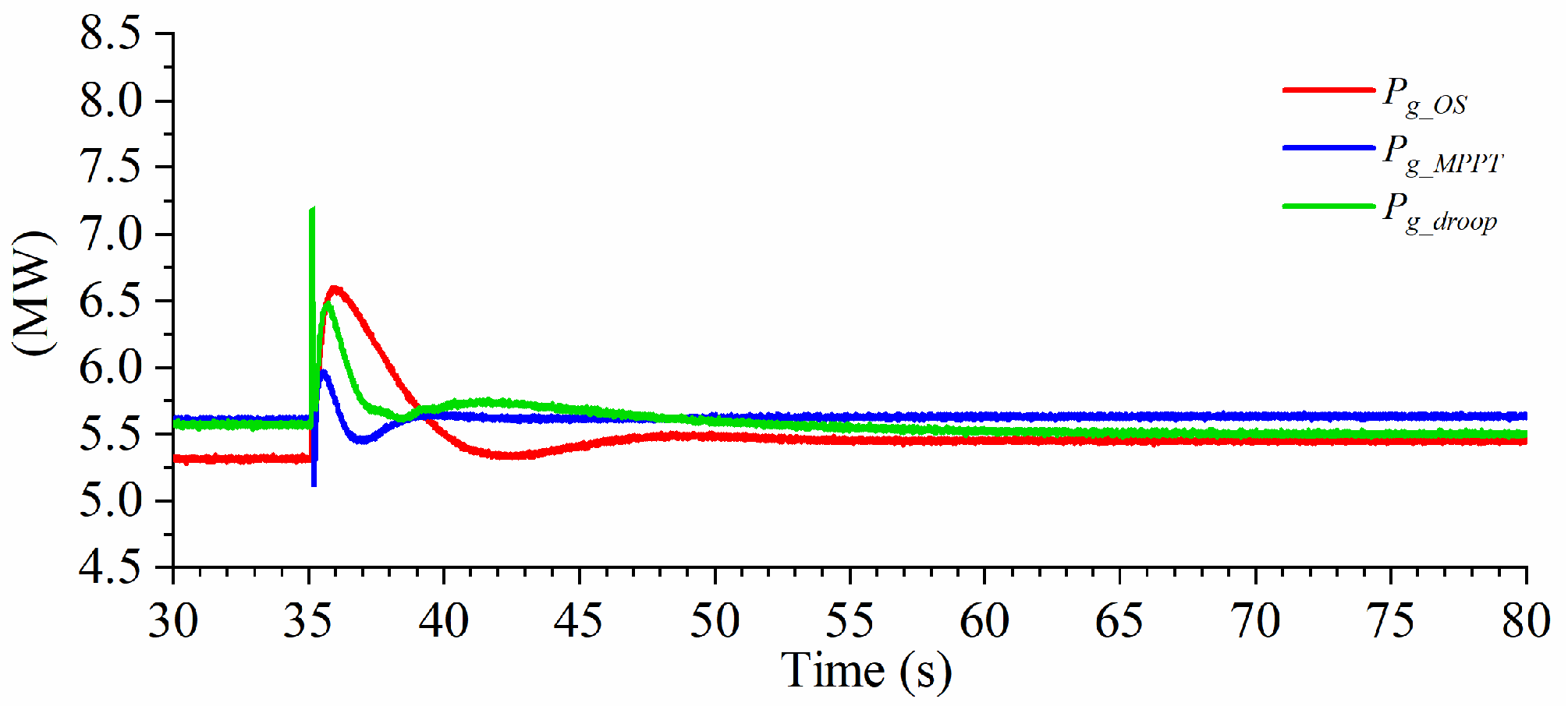
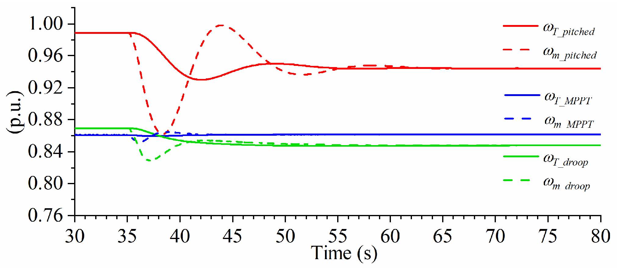
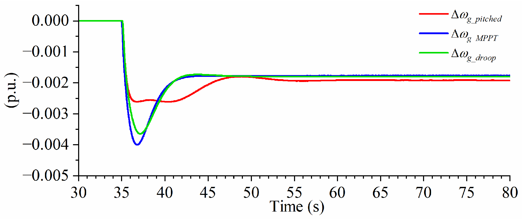
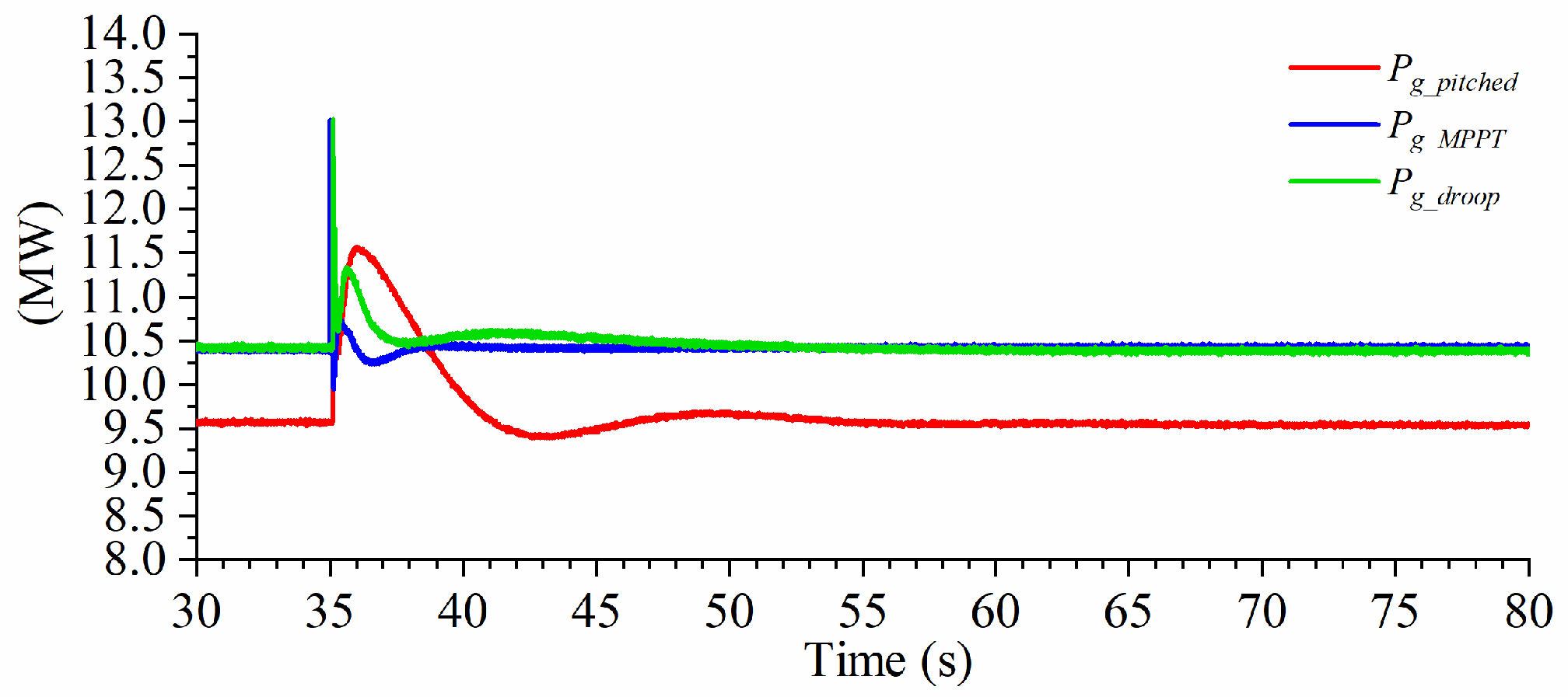
4.1. Constant Wind Speeds

4.1.1. Over-Speeding Control Performance

In this scenario, a constant and relatively low wind speed of 7.63 m/s (0.72 p.u.) is simulated, which is a relatively low wind speed. At this wind speed, the proposed control method operates the wind turbine in the over-speeding mode with the prescribed 10% power margin. The performance of the proposed method is then compared with the traditional MPPT method and the MPPT plus frequency droop method presented in [23]. In the MPPT method, the power reference from (4) is directly sent to the swing equation block of the VSG. In the MPPT plus frequency droop method, the power reference from (4) is supplemented by grid frequency droop control, as specified in [23]. The load is initially 9 MW, and then a sudden 5 MW load increment is introduced at t = 35 sec to evaluate dynamic performance. Figure 13 displays the wind turbine rotor’s angular speed ( ω T ) and the PMSG rotor’s mechanical angular speed ( ω m ) for the three methods.
It is clearly observed that the rotor speeds of both the wind turbine and the PMSG in all methods converge to new steady states. However, the wind turbine rotor speed undergoes slower and smaller fluctuations compared to the PMSG rotor speed in all methods. This distinction can be attributed to the drivetrain dynamics and the wind turbine’s considerably larger moment of inertia. Notably, the rotor speeds of the proposed method remain higher than those of the other two methods, due to its over-speeding operation. When subjected to a sudden load increase, the rotor speeds in the proposed method decline, thereby leveraging the kinetic energy stored in the rotating masses to deliver additional active power. In contrast, the rotor speeds in the MPPT method remain largely unchanged throughout the evaluation due to the absence of additional power reserves. In the MPPT plus frequency droop method, the rotor speeds are lower than those in the MPPT method. These different results occur because the grid frequency droop control enables the WECS to operate to the left of the maximum power points in Figure 11, when the grid frequency is lower than the nominal grid frequency.
The grid angular frequencies of the three methods are also compared to assess their frequency regulation capabilities. Given their different initial operating conditions, only the angular frequency deviations from their initial values (0.99859 p.u. for the MPPT method, 0.99848 p.u. for the proposed method, and 0.99858 p.u. for the MPPT plus frequency droop method) are presented in Figure 14. Since the MPPT method does not contribute to primary frequency regulation, the grid frequency is solely regulated by the AC grid. Although the MPPT plus frequency droop method contributes to frequency regulation, its effectiveness is limited. This limitation arises because the power reference from the MPPT algorithm decreases as the rotor decelerates to release kinetic energy. Conversely, the proposed method enhances frequency support for the AC grid by arresting the frequency decline through a deloaded power reserve. This approach leads to a noticeable improvement in the grid frequency nadir by around 0.00062 p.u. (0.0372 Hz) compared with the MPPT plus frequency droop method. Additionally, the grid frequency recovers to a new steady state relatively closer to its initial steady state using the proposed method.
The active and reactive power outputs are displayed in Figure 15 and Figure 16, respectively. Initially, due to the proposed deloading operation, the WECS generates less active power compared to the conventional MPPT method and the MPPT plus frequency droop method. Upon the load increase, the proposed method increases mechanical power output by decreasing the turbine rotor speed for frequency regulation. As the wind turbine rotor speed varies over time, the active power reference dispatched to the GSC is adaptively adjusted to prevent further decreases in turbine speed. However, the MPPT method makes the WECS generate constant active power despite the short transient following the load change. The MPPT plus frequency droop method, on the other hand, produces more active power than the MPPT method but experiences a higher spike during the transient phase. It is also noted that the WECS in all methods is capable of regulating the output voltage. When the load increases, the GSC under all methods senses a voltage dip at its output terminal and responds by increasing reactive power generation to stabilize the voltage, as shown in Figure 16.
Since MMCs are used in both the MSC and GSC of the simulated system, ancillary controls are important for their efficient and stable operation. Figure 17 and Figure 18 compare the control performances of the proposed method before and after applying these ancillary controls. Taking the GSC as an example, Figure 17 shows the upper and lower arm currents, i a u and i a l , respectively, along with the circulating current component i d i f f _ a for phase leg a. It is clear that once the CCC is activated, there is a noticeable reduction in arm current distortion and the circulating current is effectively suppressed, showing a smoother DC component. In addition, the LVC enables the average SM capacitor voltages to be more evenly balanced across all three phases, as evidenced in Figure 18.

4.1.2. Pitched Control Performance

A relatively high wind speed of 9.43 m/s (0.89 p.u.) is simulated in this scenario, at which the pitched control is automatically activated. Correspondingly, the pitch angle reference is set to 3.3825° according to the offline look-up table. A comparison is still made with the other two methods under the same loading condition as in Section 4.1.1.
Figure 19 depicts the angular speeds of the wind turbine and PMSG rotors. Because the wind speed is already above the upper bound v w _ h (8.83 m/s), the initial wind turbine rotor speed is clamped close to the maximum allowable rotor speed, consistent with the design of the pitch-controlled curves. At higher wind speeds, the turbine accumulates more kinetic energy in its spinning rotor. Upon the sudden load increase at t = 35 sec, the stored energy is rapidly released following the designed pitch-controlled curve to support the grid. When comparing Figure 13 and Figure 19, it is observed that the rotor speeds in the proposed method for this scenario exhibit a more pronounced swing than those in the first scenario due to the greater stored kinetic energy, even though the overall waveforms are similar. Furthermore, the initial rotor speeds in the MPPT plus frequency droop control method are higher than those observed in the MPPT method, due to the grid frequency in this scenario being above the nominal value (1.00069 p.u. for the MPPT, 1.00014 p.u. for the proposed method, and 1.00070 p.u. for the MPPT plus frequency droop control method). Under the grid frequency droop mechanism, excess kinetic energy is accumulated in the rotating masses, which results in higher rotor speeds. When the load increases, the rotor speeds are reduced to aid in frequency regulation, in contrast with the MPPT method.
Figure 20 provides a comparison of the grid angular frequency deviations among the three methods in this higher wind speed scenario. As previously noted, the initial grid frequencies are above the nominal value, attributed to the higher active power outputs from the WECS than the base load, as illustrated in Figure 21. When the load increment occurs, the proposed approach consistently outperforms in enhancing the frequency nadir. However, the grid frequency recovery is slightly limited in this case because the designed pitch-controlled curve commands the WECS to reduce its active power output as the turbine rotor speed decreases over time. In addition, during the transient phase, the MPPT plus frequency droop control method supplies more active power than the traditional MPPT method, improving the system’s response to frequency deviations.
Moreover, the reactive power outputs for all methods are compared in Figure 22. The reactive power outputs in the MPPT method and the MPPT plus frequency droop control method are similar and remain negative, indicating an above-nominal output voltage at the GSC terminal. The voltage regulation observed is similar to the under-excitation mode of conventional SGs.
Figure 23 traces the progression of the DC-link voltage for all methods throughout the simulations. A greater fluctuation in V d c for the proposed deloading method is caused by a larger instantaneous power imbalance between the MSC and the GSC. Furthermore, the comparison shows a more pronounced change in V d c when comparing the MPPT plus frequency droop control method with the conventional MPPT method, which indicates the effect of integrating a frequency droop mechanism. These observations confirm that the DC-link voltages are well regulated in all methods, with the MSC dynamically adjusting the electromagnetic torque of the PMSG.

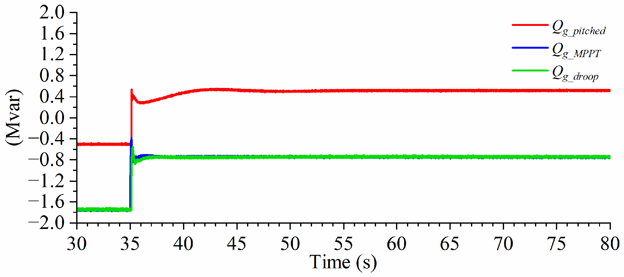
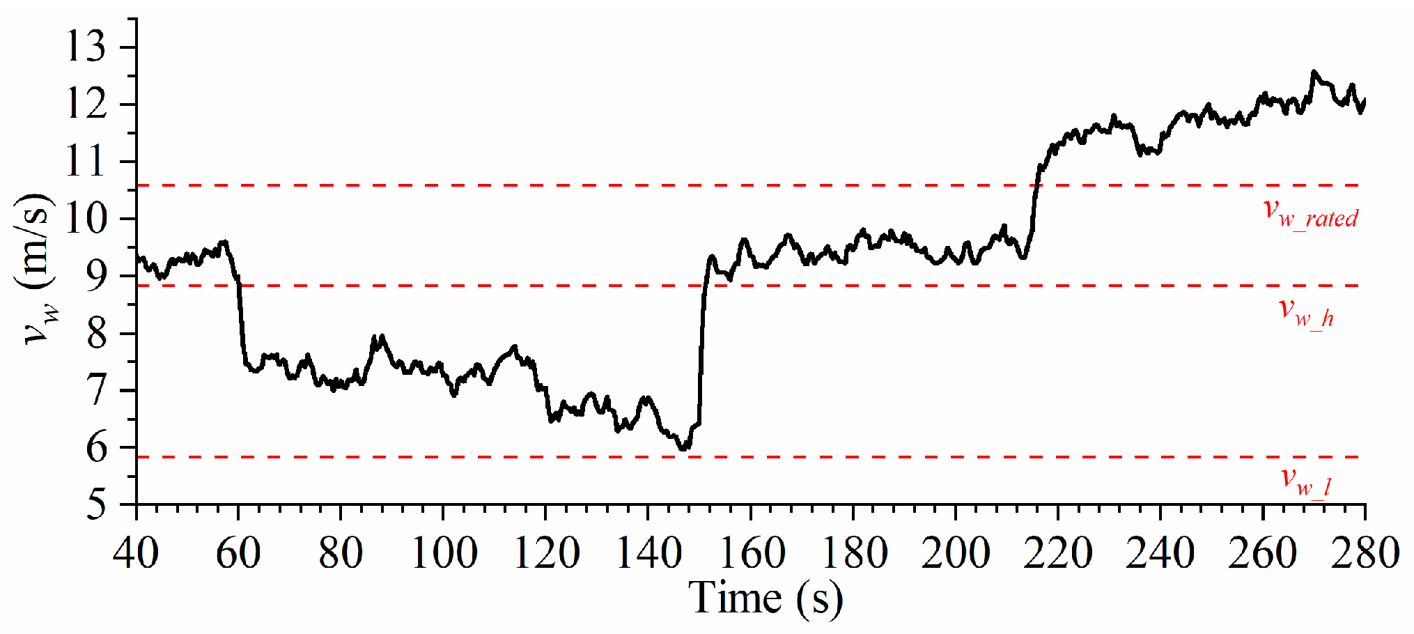
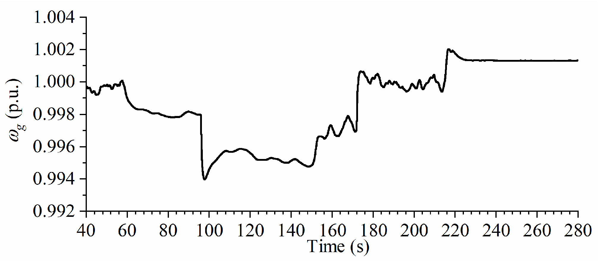
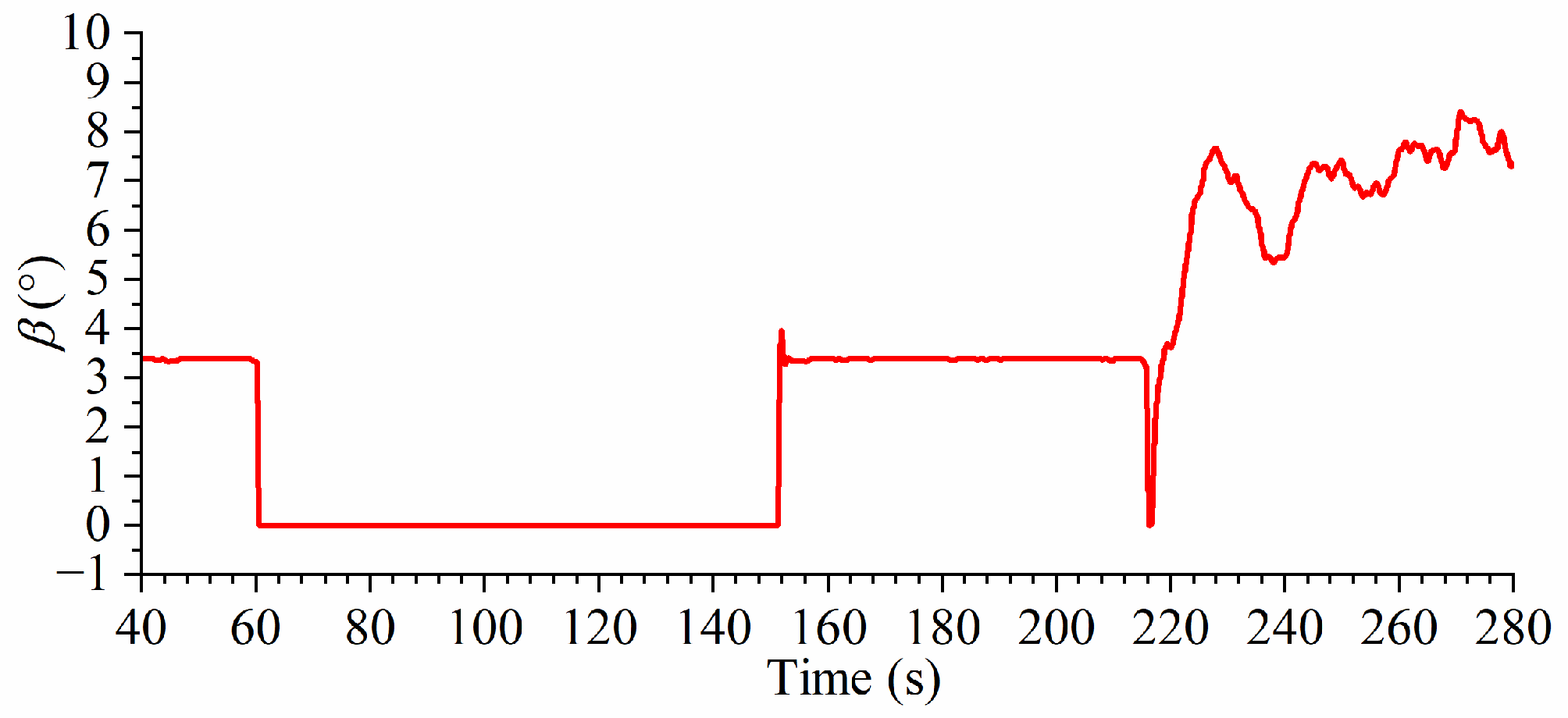
4.2. Varying Wind Speeds
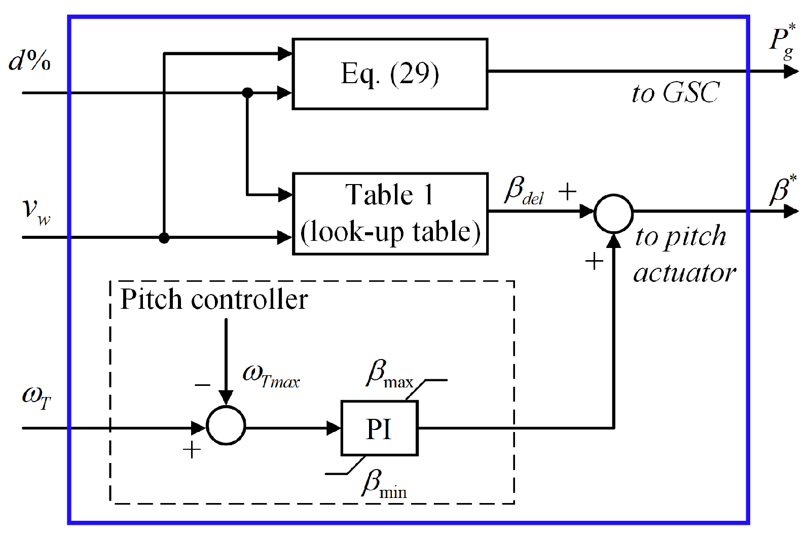
In order to further evaluate the dynamical performance of the proposed hybrid deloading approach in a practical setting, a varying wind speed scenario is designed. Figure 24 shows a time series of offshore wind speeds sampled at 2 Hz. A dynamic load is simulated with a base load of 10 MW, and a step load of 6 MW is connected at t = 96 sec and disconnected at t = 172 s. In this scenario, the angular speeds of the wind turbine and PMSG rotors are shown in Figure 25.
The rotor speeds of the wind turbine and the PMSG exhibit different dynamical responses as the wind speed evolves. The rotor speed of the wind turbine is steadier due to the larger moment of inertia. Furthermore, it is well regulated within the permissible range. Figure 26 illustrates the grid angular frequency, while Figure 27 displays the active power outputs of both the WECS and the AC grid.
It is clearly demonstrated that when the step load is connected at t = 96 sec, the WECS operating in the over-speeding mode is able to assist the grid in arresting the grid frequency decline. In addition, when the step load is disconnected at t = 172 sec, the WECS in the pitch-controlled mode adjusts its active power output to help the AC grid counter the grid frequency rise. When the turbine rotor speed rises beyond the maximum allowable value after t = 216.4 s, the pitch controller is activated to regulate the rotor speed. Concurrently, the WECS starts to follow a deloaded constant active power reference, as shown in Figure 27. The simulation results demonstrate the smooth operational transitions facilitated by the proposed method.
The response of the pitch actuator is presented in Figure 28. It shows that the proposed hybrid deloading method can effectively generate pitch angle references that adapt to varying grid conditions. This adaptability ensures effective frequency regulation throughout the simulation.

4.3. Future Scope

The proposed control method has its limitations including economic drawbacks due to deloading compared to MPPT methods. However, the opportunity costs could be compensated for by participating in reserve markets. On the other hand, advancements in ESS technologies, particularly long-duration and large-scale hydrogen storage, could make the “OSW + hydrogen” solution economically viable for enhanced frequency support. The economic benefits of these options could be further quantified and leveraged. Furthermore, this study’s focus on individual wind turbine control does not account for variable wind speeds across wind farms due to the wake effect. Exploring adaptive deloading factors that consider both grid and wind conditions could further enhance system performance. As a next step, we plan to develop distributed, coordinated control strategies for offshore wind farms integrated with hydrogen storage to improve frequency regulation and optimize cost-effectiveness.

5. Conclusions

This paper proposed a hybrid deloading GFM approach for MMC-based WECSs. Based on real-time wind speed measurements, it enables seamless transitions between different control modes to regulate the grid system frequency effectively. Notably, the proposed control eliminates the need for a PLL for frequency measurement, thus avoiding PLL-related instability issues in weak grid conditions. Rigorous numerical simulations conducted in MATLAB/Simulink have validated the ability of the proposed method to provide robust inertial and frequency support to the grid across varying wind and loading conditions. The results confirm that the proposed method offers enhanced frequency regulation capabilities during both transient and steady-state conditions. Moreover, this study has addressed the key operational challenges associated with MMCs, including circulating currents and capacitor voltage imbalances, which paves the way for more reliable and efficient practical implementations in OSW.

Author Contributions

Validation, J.Z.; formal analysis, J.Z. and J.L.; writing—original draft preparation, J.Z.; writing—review and editing, J.L.; supervision, J.L.; funding acquisition, J.L. All authors have read and agreed to the published version of the manuscript.

Funding

This research was funded in part by the U.S. National Science Foundation grants ECCS-1952683 and IUSE-2121242.

Data Availability Statement

Data are contained within the article.

Conflicts of Interest

The authors declare no conflicts of interest.

References

  1. FACT SHEET: Biden-Harris Administration Announces New Actions to Expand U.S. Offshore Wind Energy. Available online: https://www.whitehouse.gov/briefing-room/statements-releases/2022/09/15/fact-sheet-biden-harris-administration-announces-new-actions-to-expand-u-s-offshore-wind-energy (accessed on 21 December 2023).
  2. Offshore Wind. Available online: https://dep.nj.gov/offshorewind (accessed on 21 December 2023).
  3. Anaya-Lara, O.; Tande, J.O.; Uhlen, K.; Merz, K. Offshore Wind Energy Technology; John Wiley & Sons: Hoboken, NJ, USA, 2018; pp. 20–23. [Google Scholar]
  4. Catalán, P.; Wang, Y.; Arza, J.; Chen, Z. A Comprehensive Overview of Power Converter Applied in High-Power Wind Turbine: Key Challenges and Potential Solutions. IEEE Trans. Power Electron. 2023, 38, 6169–6195. [Google Scholar] [CrossRef]
  5. Li, K.; Liao, Y.; Lin, H.; Liu, R.; Zhang, J. Circulating Current Suppression with Improved DC-Link Power Quality for Modular Multilevel Converter. IET Gener. Transm. Distrib. 2018, 12, 2220–2230. [Google Scholar] [CrossRef]
  6. Li, K.; Liao, Y.; Liu, R.; Zhang, J. An Improved Nearest-Level Modulation for Modular Multi-Level Converters. Int. J. Power Electron. 2018, 9, 150–166. [Google Scholar] [CrossRef]
  7. Yaramasu, V.; Wu, B. Model Predictive Control of Wind Energy Conversion Systems; John Wiley & Sons: Hoboken, NJ, USA, 2017; pp. 39–44. [Google Scholar]
  8. Rosso, R.; Wang, X.; Liserre, M.; Lu, X.; Engelken, S. Grid-Forming Converters: Control Approaches, Grid-Synchronization, and Future Trends—A Review. IEEE Open J. Ind. Appl. 2021, 2, 93–109. [Google Scholar] [CrossRef]
  9. Pan, D.; Wang, X.; Liu, F.; Shi, R. Transient Stability of Voltage-Source Converters with Grid-Forming Control: A Design-Oriented Study. IEEE Trans. Emerg. Sel. Topics Power Electron. 2020, 8, 1019–1033. [Google Scholar] [CrossRef]
  10. Qoria, T.; Rokrok, E.; Bruyere, A.; François, B.; Guillaud, X. A PLL-Free Grid-Forming Control with Decoupled Functionalities for High-Power Transmission System Applications. IEEE Access 2020, 8, 197363–197378. [Google Scholar] [CrossRef]
  11. Chen, J.; Liu, M.; Guo, R.; Zhao, N.; Milano, F.; O’Donnell, T. Co-ordinated Grid Forming Control of AC-Side-Connected Energy Storage Systems for Converter-Interfaced Generation. Int. J. Electr. Power Energy Syst. 2021, 133, 107201. [Google Scholar] [CrossRef]
  12. Zhao, F.; Wang, X.; Zhou, Z.; Harnefors, L.; Svensson, J.R.; Kocewiak, L.H.; Gryning, M.P.S. Control Interaction Modeling and Analysis of Grid-Forming Battery Energy Storage System for Offshore Wind Power Plant. IEEE Trans. Power Syst. 2022, 37, 497–507. [Google Scholar] [CrossRef]
  13. Huang, L.; Wu, C.; Zhou, D.; Chen, L.; Pagnani, D.; Blaabjerg, F. Challenges and Potential Solutions of Grid-Forming Converters Applied to Wind Power Generation System—An Overview. Front. Energy Res. 2023, 11, 1040781. [Google Scholar] [CrossRef]
  14. Strunz, K.; Almunem, K.; Wulkow, C.; Kuschke, M.; Valescudero, M.; Guillaud, X. Enabling 100% Renewable Power Systems Through Power Electronic Grid-Forming Converter and Control: System Integration for Security, Stability, and Application to Europe. Proc. IEEE 2023, 111, 891–915. [Google Scholar] [CrossRef]
  15. Morren, J.; de Haan, S.W.H.; Kling, W.L.; Ferreira, J.A. Wind Turbines Emulating Inertia and Supporting Primary Frequency Control. IEEE Trans. Power Syst. 2006, 21, 433–434. [Google Scholar] [CrossRef]
  16. Li, Y.; Yuan, X.; Li, J.; Xiao, H.; Xu, Z.; Du, Z. Novel Grid-Forming Control of PMSG-Based Wind Turbine for Integrating Weak AC Grid Without Sacrificing Maximum Power Point Tracking. IET Gener. Transm. Distrib. 2021, 15, 1613–1625. [Google Scholar] [CrossRef]
  17. Lu, Z.; Ye, Y.; Qiao, Y. An Adaptive Frequency Regulation Method with Grid-Friendly Restoration for VSC-HVDC Integrated Offshore Wind Farms. IEEE Trans. Power Syst. 2019, 34, 3582–3593. [Google Scholar] [CrossRef]
  18. Avazov, A.; Colas, F.; Beerten, J.; Guillaud, X. Application of Input Shaping Method to Vibrations Damping in a Type-IV Wind Turbine Interfaced with a Grid-Forming Converter. Electr. Power Syst. Res. 2022, 210, 108083. [Google Scholar] [CrossRef]
  19. Zhang, J.; Li, J. Modeling and Control of an Islanded Campus Microgrid with Coordinated CHP and PV Systems. In Proceedings of the 2021 IEEE Power & Energy Society General Meeting (PESGM), Washington, DC, USA, 26–29 July 2021. [Google Scholar]
  20. Lyu, X.; Groß, D. Grid Forming Fast Frequency Response for PMSG-Based Wind Turbines. IEEE Trans. Sustain. Energy 2024, 15, 23–38. [Google Scholar] [CrossRef]
  21. Wilches-Bernal, F.; Chow, J.H.; Sanchez-Gasca, J.J. A Fundamental Study of Applying Wind Turbines for Power System Frequency Control. IEEE Trans. Power Syst. 2016, 31, 1496–1505. [Google Scholar] [CrossRef]
  22. Díaz-González, F.; Hau, M.; Sumper, A.; Gomis-Bellmunt, O. Participation of Wind Power Plants in System Frequency Control: Review of Grid Code Requirements and Control Methods. Renew. Sustain. Energy Rev. 2014, 34, 551–564. [Google Scholar] [CrossRef]
  23. Fernández-Bustamante, P.; Barambones, O.; Calvo, I.; Napole, C.; Derbeli, M. Provision of Frequency Response from Wind Farms: A Review. Energies 2021, 14, 6689. [Google Scholar] [CrossRef]
  24. Deng, F.; Chen, Z. Elimination of DC-Link Current Ripple for Modular Multilevel Converters with Capacitor Voltage-Balancing Pulse-Shifted Carrier PWM. IEEE Trans. Power Electron. 2014, 30, 284–296. [Google Scholar] [CrossRef]
  25. Castillo, O.C.; Andrade, V.R.; Rivas, J.J.R.; González, R.O. Comparison of Power Coefficients in Wind Turbines Considering the Tip Speed Ratio and Blade Pitch Angle. Energies 2023, 16, 2774. [Google Scholar] [CrossRef]
  26. Definition of the IEA 15-Megawatt Offshore Reference Wind; National Renewable Energy Laboratory: Golden, CO, USA, 2020.
  27. Boukhezzar, B.; Siguerdidjane, H. Nonlinear Control of a Variable-Speed Wind Turbine Using a Two-Mass Model. IEEE Trans. Energy Convers. 2011, 26, 149–162. [Google Scholar] [CrossRef]
  28. Kim, J.; Lee, S.H.; Park, J.W. Inertia-Free Stand-Alone Microgrid—Part II: Inertia Control for Stabilizing DC-Link Capacitor Voltage of PMSG Wind Turbine System. IEEE Trans. Ind. Appl. 2018, 54, 4060–4068. [Google Scholar] [CrossRef]
  29. Wu, B.; Lang, Y.; Zargari, N.; Kouro, S. Power Conversion and Control of Wind Energy Systems; John Wiley & Sons: Hoboken, NJ, USA, 2011; pp. 277–279. [Google Scholar]
  30. Ebrahimi, M.; Khajehoddin, S.A.; Karimi-Ghartemani, M. An Improved Damping Method for Virtual Synchronous Machines. IEEE Trans. Sustain. Enery. 2019, 10, 1491–1500. [Google Scholar] [CrossRef]
  31. Half-Bridge MMC. Available online: https://www.mathworks.com/help/sps/powersys/ref/halfbridgemmc.html (accessed on 26 December 2023).
  32. Du, S.; Dekka, A.; Wu, B.; Zargari, N. Modular Multilevel Converters: Analysis, Control, and Applications; John Wiley & Sons: Hoboken, NJ, USA, 2018. [Google Scholar]
  33. Kundur, P.S. Power System Stability and Control; McGraw Hill: New York, NY, USA, 1994; p. 428. [Google Scholar]
  34. Hur, S. Short-Term Wind Speed Prediction Using Extended Kalman Filter and Machine Learning. Energy Rep. 2021, 7, 1046–1054. [Google Scholar] [CrossRef]
Figure 1. Structure of the MMC-based WECS interfaced with an AC grid.
Energies 17 01253 g001
Figure 2. Operating curves of the IEA 15 MW wind turbine.
Energies 17 01253 g002
Figure 3. Pitch actuator model.
Energies 17 01253 g003
Figure 4. Configuration of a general three-phase MMC.
Energies 17 01253 g004
Figure 5. Current control diagram of the MSC.
Energies 17 01253 g005
Figure 6. Reactive power control diagram of the GSC.
Energies 17 01253 g006
Figure 7. Dual control diagram of the GSC.
Energies 17 01253 g007
Figure 8. VSG control diagram of the GSC.
Energies 17 01253 g008
Figure 9. Ancillary control diagram.
Energies 17 01253 g009
Figure 10. Equivalent AC grid dynamic model.
Energies 17 01253 g010
Figure 11. P T ω T curves of the IEA 15 MW wind turbine.
Energies 17 01253 g011
Figure 12. Proposed hybrid deloading control diagram.
Energies 17 01253 g012
Figure 13. Rotor speeds for all methods when v w = 0.72   p . u .
Energies 17 01253 g013
Figure 14. Grid angular frequency deviations for all methods when v w = 0.72   p . u .
Energies 17 01253 g014
Figure 15. Active power outputs for all methods when v w = 0.72   p . u .
Energies 17 01253 g015
Figure 16. Reactive power outputs for all methods when v w = 0.72   p . u .
Energies 17 01253 g016
Figure 17. Performance comparison of arm currents and circulating currents before (a) and after (b) activation of CCC in GSC.
Energies 17 01253 g017
Figure 18. Performance comparison of average SM capacitor voltages before (a) and after (b) activation of LVC in GSC.
Energies 17 01253 g018
Figure 19. Rotor speeds for all methods when v w = 0.89   p . u .
Energies 17 01253 g019
Figure 20. Grid angular frequency deviations for all methods when v w = 0.89   p . u .
Energies 17 01253 g020
Figure 21. Active power outputs for all methods when v w = 0.89   p . u .
Energies 17 01253 g021
Figure 22. Reactive power outputs for all methods when v w = 0.89   p . u .
Energies 17 01253 g022
Figure 23. DC-link voltages for all methods when v w = 0.89   p . u .
Energies 17 01253 g023
Figure 24. Time series of offshore wind speeds.
Energies 17 01253 g024
Figure 25. Angular speeds of the wind turbine and PMSG rotors.
Energies 17 01253 g025
Figure 26. Grid angular frequency.
Energies 17 01253 g026
Figure 27. Active power outputs of the WECS and the AC grid.
Energies 17 01253 g027
Figure 28. Pitch angle response of the pitch actuator.
Energies 17 01253 g028
Table 1. Look-up table for the pitch angles considering d = 10 % .
vw (m/s)βdel (°)
8.833.2680
8.873.2987
9.253.3849
9.663.3790
10.083.3021
10.493.1655
Table 2. Parameters of the modeled system.
Wind turbine
Power coefficient C p m a x 0.481Optimal TSR λ T _ o p t 8.878
Rotor radius R T (m)120Rated speed ω T r a t e d (rad/s)0.7835
Min. speed ω T m i n (rad/s)0.5236Max. speed ω T m a x (rad/s)0.7917
Moment of inertia J T (kg·m2)3.525 × 10⁸Viscous friction coeff. KT (p.u.)2 × 10⁻³
Stiffness coeff. KS (p.u.)0.4Damping coeff. BS (p.u.)1.5
Pitch actuator coeffs. [a b c][1 5 28]Pitch angle limits [βmin βmax] (°)[0 27]
Change rates [ β ˙ m i n   β ˙ m a x ] (°/s)[−10 10]
PMSG
Rated electrical power ((MW) 15Rated stator frequency (Hz)12.6
Rated phase voltage (V rms)4770Flux linkage ψ f (Wb)79.321
Stator resistance R s (Ω)0.16Self-inductance L s (H)0.0204
Number of pole pairs (Pp)100Moment of inertia J m (kg·m2)3.1 × 10⁷
Viscous friction coeff. Km (p.u.)2 × 10⁻³
MMCs
Nominal DC-link voltage (kV)16Number of SMs per arm20
Arm inductance L a r m (mH)3.5Arm resistance R a r m (mΩ)80
DC-link capacitor C d c (mF)200PWM carrier frequency (Hz)600
Droop coeff. k v (Var/V)2.3 × 104Droop coeff. k f n (W/rad/s)2.06 × 106
VSG time constant H v i r (s)4.2Power damping coeff. D p (p.u.)0.03
LC filter
Resistance R f (mΩ)20Inductance L f (mH)1
Capacitance C f (mF)40
Step-up transformer
Power rating (MVA)20Voltages: 8262V-D1/66kV-Yg
AC grid
Droop coeff. R d r o o p (p.u.)0.02Turbine time constants [ T n   T d ][2 6]
Power rating S g r n (MVA)50Active power ref. P g r n ( p . u . ) 0
Inertia time constant H e q (s)6.7
Disclaimer/Publisher’s Note: The statements, opinions and data contained in all publications are solely those of the individual author(s) and contributor(s) and not of MDPI and/or the editor(s). MDPI and/or the editor(s) disclaim responsibility for any injury to people or property resulting from any ideas, methods, instructions or products referred to in the content.

