1. Introduction
A variety of carbon-containing waste materials with different properties consisting predominantly of C, H, and O elements is commonly referred to as organic waste. The gasification of liquid/solid organic wastes with steam and carbon dioxide is considered a competitive and cost-effective waste processing technology [
1,
2], especially when the heat required for the processing is obtained by environmentally clean technologies (plasma [
3], microwave [
4], solar [
5], etc.), other than waste incineration. The objective of gasification is to completely convert the carbon contained in the waste. The gasification process generally includes waste drying, pyrolysis, and thermal cracking followed by the partial oxidation of the produced gases, tar, and char at higher temperatures, leading to the formation of a product gas (a mixture of H
2, CO, CH
4, CO
2, etc.) commonly referred to as syngas or energy gas depending on its further application. The process includes multiple heterogeneous/homogeneous exothermic/endothermic reactions between molecules, atoms, and active radicals as well as ionized and electronically excited species in case of plasma gasification. The efficiency of the gasification process is high, with a high yield of the produced gas and the less carbon remains in the by-products (a high completeness of carbon conversion into CO). Thermodynamic calculations indicate [
6] that at gasification temperatures ~600 °C, carbon and oxygen are present as CO
2, tar, and char; at temperatures above ~900 °C, CO
2 breaks down to CO in the presence of carbon and the available oxygen mostly reacts with the carbon to form CO and CO
2; and at temperatures above ~1500 °C tar and char are completely transformed to syngas or energy gas composed mainly of H
2 and CO or CH
4 and CO, respectively. As for the effect of gasification pressure, the increase in pressure at a fixed gasification temperature of 1000 °C decreases the mole fractions of H
2 and CO in the produced gas and increases those of CO
2 and CH
4 [
7]. A similar trend exists at temperatures above 1500 °C but the differences in product yields look negligible.
The use of steam and/or CO
2 as a gasifying agent (GA) has a number of advantages [
8,
9]. Firstly, the produced gas is not diluted with other gases. Secondly, waste gasification with steam/CO
2 requires less GA due to their high enthalpies. Thirdly, the use of an H
2O/CO
2 mixture allows controlling the composition of the produced gas. Fourthly, the use of steam as GA increases economic efficiency [
10,
11]. Fifthly, in the absence of free oxygen, the produced gas does not contain dioxins and furans, which facilitates gas purification operations [
12]. Sixth, the amount of H
2 produced by steam gasification of waste is several times greater than by air gasification [
13].
Depending on the level of the gasification temperature, all gasification technologies are divided into low-temperature and high-temperature technologies [
14]. Low-temperature gasification is usually carried out at temperatures below 1000 °C and produces gas, char, and slag. In the literature, there are several noteworthy thermodynamic studies on the low-temperature steam gasification of organic wastes. Thus, the thermodynamic calculations of the steam gasification of woody biomass and cellulose at atmospheric pressure using the minimization of Gibbs free energy were reported in [
15,
16]. Based on the results of the models, the optimal ranges of the steam–feedstock (S/F) ratio were recommended. Various modeling approaches to simulate the steam gasification of biomass with regard to chemical and physical kinetic limitations were investigated in [
17]. An equilibrium gas–solid model based on the minimization of the Gibbs free energy was developed in [
18] for estimating the theoretical yield and the equilibrium composition of the syngas produced from a biomass during various thermochemical conversion processes (pyrolysis, partial oxidation, and gasification). The results of the calculations of the thermodynamic equilibrium state for a system initially composed of biomass and water for evaluating the influence of the gasification temperature, pressure, S/F ratio, and the type of biomass on the efficiency of the gasification system in terms of several criteria related to syngas yield and quality were reported in [
19]. The equilibrium model of steam gasification for predicting the performance of H
2-rich gas production from biomass was reported in [
20] and used to compare model predictions with experimental data. The arising discrepancies in product gas composition were explained by the lack of equilibrium conditions in a gasifier. The model was modified by correcting the equilibrium constants of several reactions by multiplying each by a pre-factor. The Aspen Plus software was applied in [
21,
22,
23] to investigate the steam gasification of biomass in terms of perspectives in H
2 production and in [
24] to study the atmospheric pressure steam co-gasification of wet sewage sludge waste and torrefied biomass using the nonstoichiometric thermodynamic equilibrium model with the Gibbs free energy minimization. For co-gasification, the water in the sewage sludge waste acted as the gasification agent. The optimal condition and blending ratio were determined by the maximum H
2 yield.
The main disadvantages of all the existing technologies of low-temperature gasification with H
2O/CO
2 are the low quality of the produced gas due to the high content of tar and CO
2, the low efficiency of gasification due to the large amount of remaining char, the difficulty of managing the quality of the produced gas due to the long residence time of feedstock in a gasifier, as well as the low yield of the produced gas due to its partial use in the production of heat for gasification. Modern R&D in the field of low-temperature gasification is mainly aimed at feedstock pre-processing and increasing its reactivity by adding catalysts [
25].
High-temperature gasification is usually carried out at temperatures above 1200 °C, which are achieved using combustion processes, as well as plasma and solar radiation [
26,
27,
28]. In the literature, there are several noteworthy thermodynamic studies on the high-temperature steam gasification of organic wastes. The results of the thermodynamic calculations for the high-temperature gasification of organic feedstock aimed at determining the maximum conversion efficiency when all carbon was oxidized to CO were reported in [
29,
30]. Calculations were made for wood and pyrolytic oil with added CO
2 and/or H
2O. Both the wood and oil produced syngas with the joint content of H
2 and CO close to 100% at temperatures above 930 °C. The contents of H
2 and CO at the steam gasification of the oil were 62 and 38 vol%., i.e., the H
2/CO ratio was about 1.6. The results of the thermodynamic calculations on the plasma-assisted gasification of a biomass (wood) considering air, CO
2, and H
2O as plasma-forming gases were presented in [
31]. The calculated values of the H
2/CO ratio varied from 0.64 to 1.07 for air plasma, from 0.18 to 1.07 for CO
2 plasma, and from 1.07 to 3.65 for H
2O plasma. The results of the thermodynamic calculations of the high-temperature steam gasification of municipal solid waste were reported in [
32]. The calculations were made for temperatures up to 2700 °C at atmospheric pressure without accounting for energy loss. The yield of syngas increased with the temperature attaining a nearly constant value above 930 °C. Solid-phase carbon was completely transformed to CO in the gas phase in these conditions. The maximum yield of syngas reached 94.5 vol% (60.9% H
2, 33.6% CO). The content of oxidants at high temperatures was very low. The content of HCl varied from 1.2 to 1.6 vol%. Sulfur was represented by H
2S up to 1630 °C, but dissociated into S and H atoms with increasing temperature. At temperatures above 1330 °C, CaCl
2, Fe, SiO, and Cl with a total content of less than 1 vol% appeared in the gas phase. This ensured 100% carbon conversion. The mineral part of the feedstock in the temperature range 930–1930 °C was mainly represented by SiO
2, CaSiO
3, Fe
3C, and Fe, but completely passed into the gas phase at temperatures above 1930 °C, forming the corresponding gaseous compounds. Importantly, there were no harmful impurities in the gas and condensed products of the high-temperature steam gasification of municipal solid waste. The low heating value (LHV) of the syngas obtained by steam gasification was 19.4 MJ/kg. The thermodynamic calculations of the high-temperature steam gasification of various organic feedstocks were performed in [
33]. The amount of steam added was equal to that required for the stoichiometric gasification of 1 kg of feedstock. The yield of syngas for all tested feedstocks at 1230 °C considered was 98–100%. For the plastics, the H
2/CO ratio was equal to 2, and the syngas LHV was 11.6 MJ/nm
3. The use of H
2O as a gasifying agent for textile provided syngas with an LHV of 11.3 MJ/nm
3. For the wood sawdust, the syngas LHV was 11.3 MJ/nm
3. The authors claimed that the calculated gas composition and the LHV of municipal solid waste and wood sawdust corresponded well to the experimental data obtained in plasma reactors and the arising differences (10 to 15%) were attributed to energy losses not included in the thermodynamic calculations.
The main advantages of the high-temperature H2O/CO2 gasification technologies are the produced high-quality gas due to the absence or very low content of tar and CO2, high gasification efficiency due to the absence or small residues of tar and char, the ease of quality control of the produced gas due to the short residence time of feedstock in a gasifier, and the high yields of the produced gas due to the use of external energy sources for delivering the heat required for gasification. In addition to these advantages, existing high-temperature plasma and solar-assisted technologies have certain limitations. Despite the fact that the typical operation temperature of plasma gasifiers is below 2000 °C, plasma technologies require large amounts of electricity for gas–plasma transition. Moreover, plasma gasifiers need special materials with a refractory lining and water cooling, as well as short-service life arc electrodes. The main limitation of solar-assisted gasifiers is their intermittent nature.
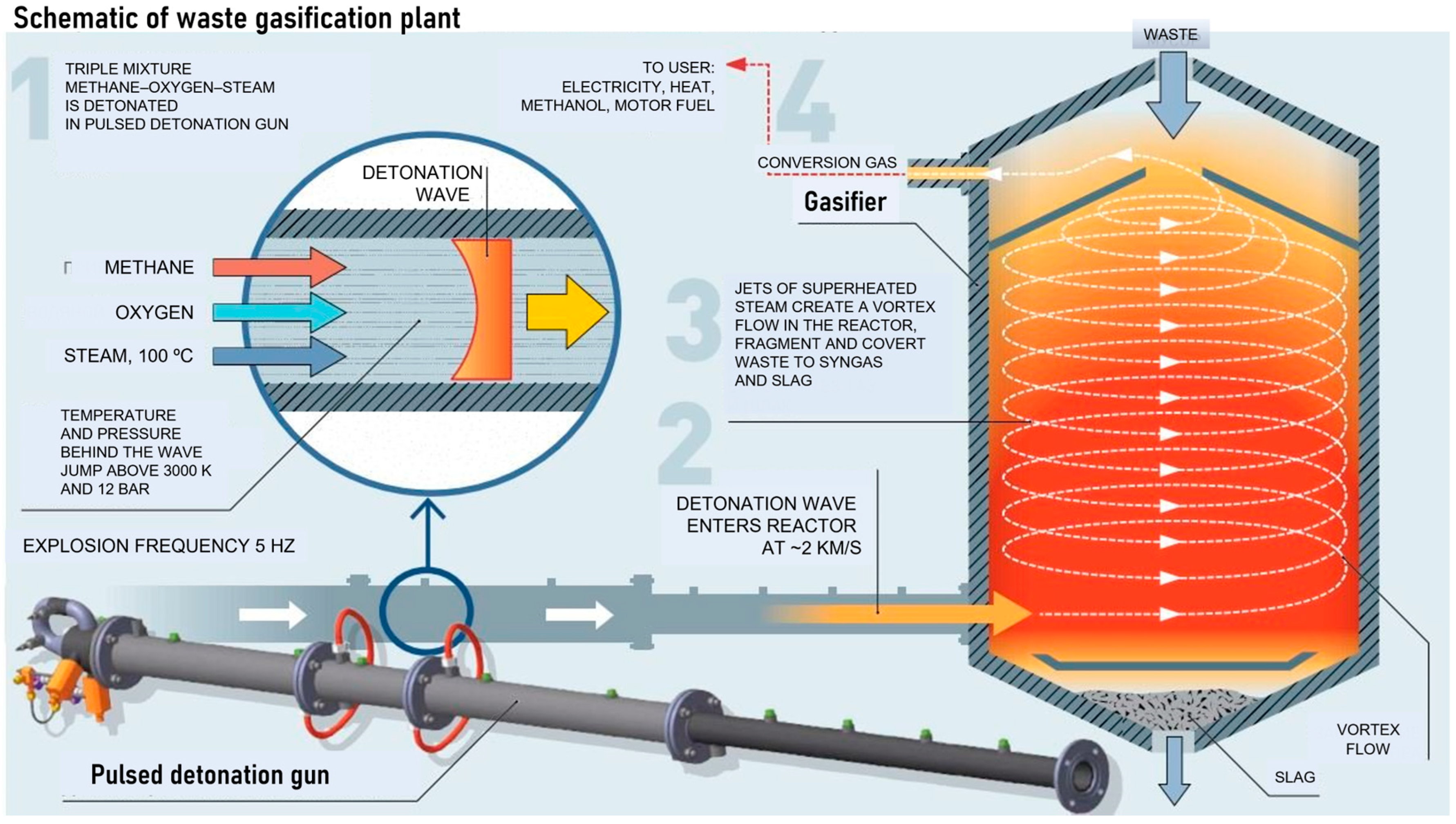
Of particular interest is the new technology for the gasification of organic wastes by the ultra-superheated H
2O/CO
2 mixture with a temperature above 1500 °C [
34]. The ability of such a GA to gasify liquid/solid organic wastes without a negative environmental impact is well known. Such a GA can be obtained by the gaseous detonation of fuel–oxidizer–diluent mixture in a pulsed detonation gun (PDG) operating in a pulse mode and periodically producing the strong shock waves and dense supersonic jets of high-temperature detonation products. At temperatures above 1500 °C, the tar and char formed at the initial stages of the gasification process are completely converted into syngas or energy gas, ideally consisting only of H
2 and CO or CH
4 and CO, respectively, in a proportion depending on the feedstock, while the cooled mineral residue consists of safe simple oxides and the aqueous solutions of oxygen-free acids, such as HCl, HF, H
2S, etc. and ammonia. The mineral residues can be used as additives to building materials, and the acids can be separated and concentrated. In other words, the new gasification technology potentially allows the complete processing of organic wastes into useful products without emissions into the atmosphere and water bodies.
The objectives of this paper are (i) to conduct the thermodynamic modeling of liquid waste oil (WO) gasification by a high-temperature GA obtained by the pulsed detonation of the stoichiometric methane–oxygen mixture; (ii) to determine the conditions for PDG self-feeding with the produced syngas; and (iii) to find out whether the gasification technology under consideration can be implemented with the replacement of oxygen with air or oxygen-enriched air, which would make the technology much more attractive and cost-effective. It is worth emphasizing that thermodynamic modeling generally provides the trends rather than the actual values of temperature and product composition. The differences between calculations and experiments are usually attributed to the imperfect mixing of components, finite rates of heat and mass transfer and chemical transformations, as well as thermal losses.
3. Results and Discussion
In this section, the properties of the GA produced by the gaseous detonations of the methane and syngas in the PDG are first demonstrated by presenting the predicted detonation parameters (detonation velocity, pressure, temperature, and density) and the composition of the detonation products of the stoichiometric methane–oxygen, methane–oxygen–steam, methane–air, and methane–oxygen-enriched air mixtures in the CJ state and in the states obtained when the CJ detonation products are expanded to pressure . Thereafter, the parameters of the syngas and energy gas predicted by models 1 and 2 are presented. Note that the products of the gaseous detonations have never been considered as a GA for organic waste gasification. In view of this, the results and analyses presented below are the novel and distinguishing features of the present research.
3.1. Detonation Parameters of Methane–Oxygen–Nitrogen–Steam Mixtures
3.1.1. Stoichiometric Methane–Oxygen Mixture
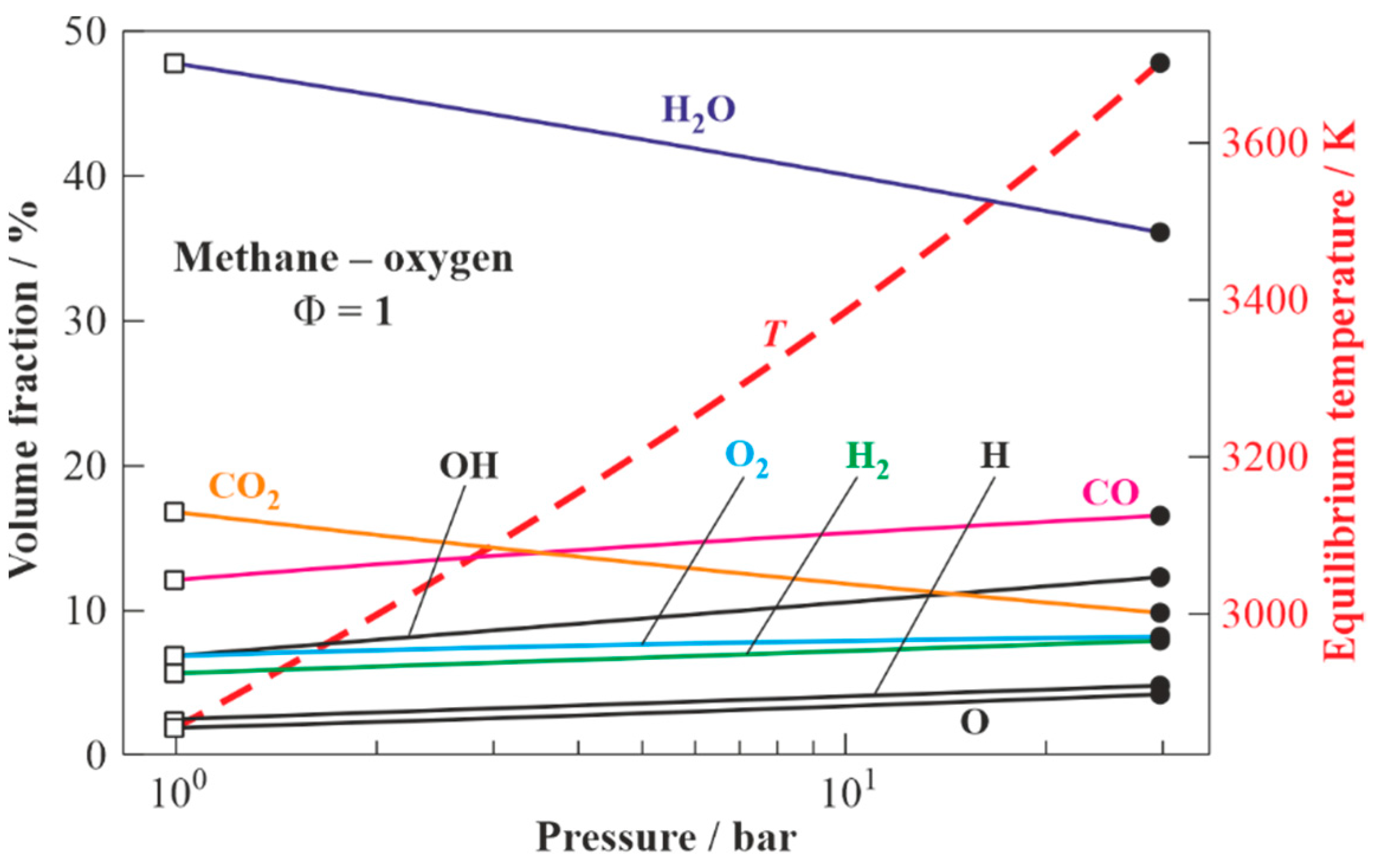
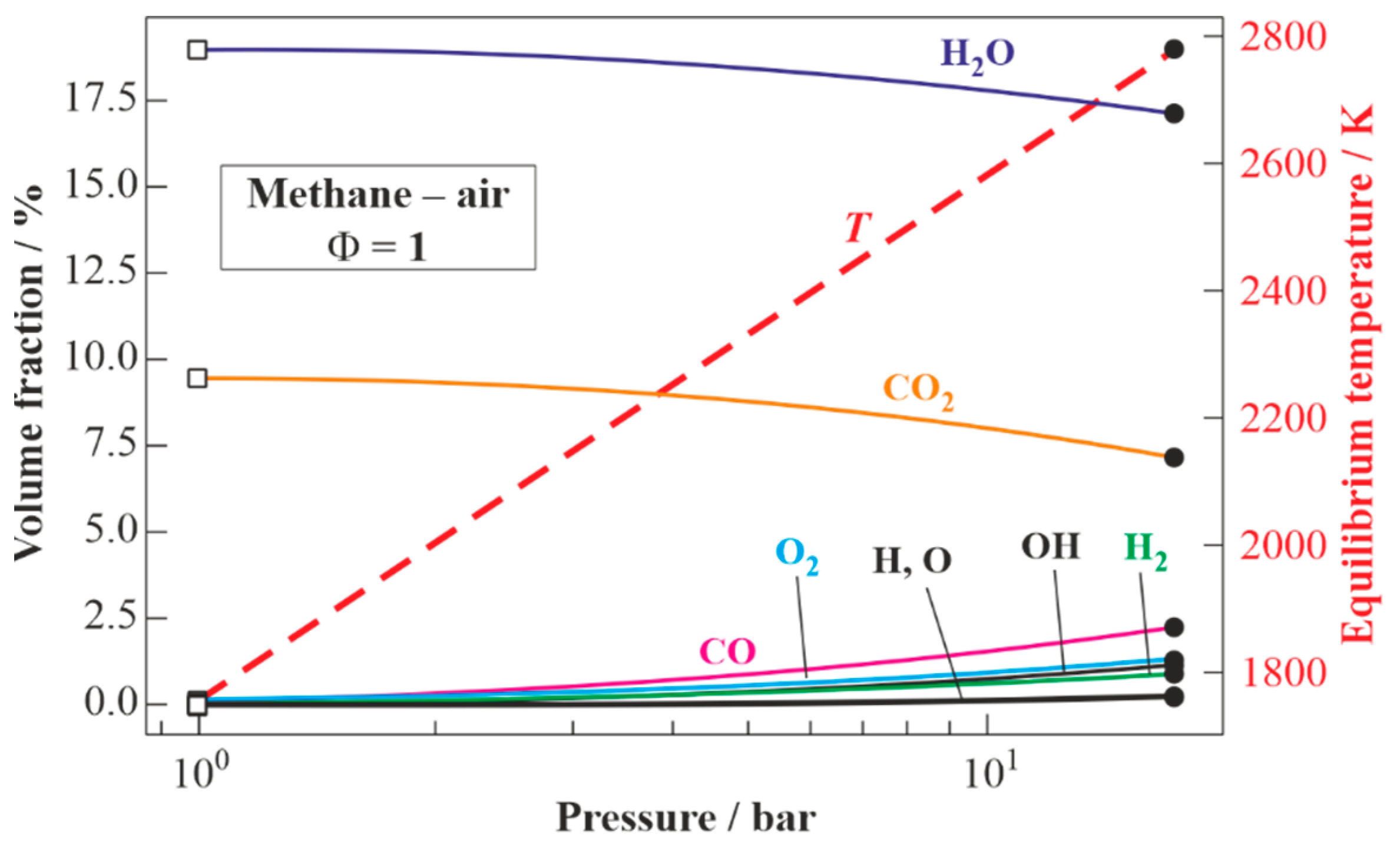
Figure 3 presents the results of the calculations for the equilibrium states of the detonation products of the stoichiometric methane–oxygen mixture: from values at the CJ state (shown by closed circles at the right) to values corresponding to the expansion of the detonation products to
= 1 bar (shown by open squares at the left). The estimated CJ detonation velocity is
= 2383 m/s (Mach number
= 6.74). The temperature, pressure, and density of the detonation products in the CJ state are 3700 K, 29.4 bar, and 2 kg/m
3, respectively. The composition of the detonation products in the CJ state includes H
2O (36 vol%), CO (16 vol%), CO
2 (10 vol%), H
2 (8 vol%), O
2 (8 vol%), as well as active radicals OH, O, and H (total 22 vol%). The temperature of the detonation products expanded to
= 1 bar is 2852 K. The expanded detonation products include H
2O (48 vol%), CO (12 vol%), CO
2 (17 vol%), H
2 (6 vol%), O
2 (7 vol%), as well as active radicals OH, O, and H (total 10 vol%).
3.1.2. Stoichiometric Methane–Oxygen–Steam Mixture
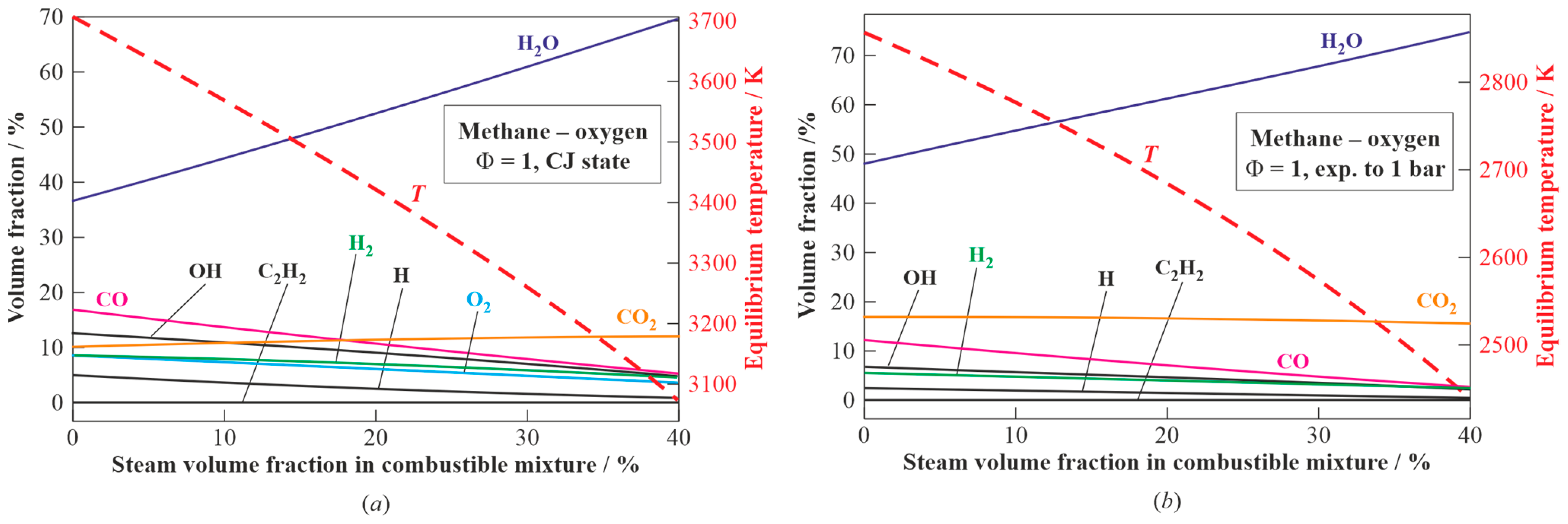
Figure 4 presents the results of the calculations for the composition and temperature of the detonation products of the stoichiometric methane–oxygen–steam mixture with steam dilution ranging from 0 to 40 vol% [
43] in the CJ state (
Figure 4a) and after expansion to
= 1 bar (
Figure 4b). The increase in steam dilution results in the decrease in the temperature of the detonation products from 3703 to 3080 K in
Figure 4a and from 2850 to 2450 K in
Figure 4b, while the concentration of steam in the detonation products increases from 36 to 70 vol% in
Figure 4a and from 48 to 74 vol% in
Figure 4b, whereas the concentration of CO
2 in the detonation products remains almost constant (10–12 vol% in
Figure 4a and 17–16 vol% in
Figure 4b).
3.1.3. Stoichiometric Methane–Air Mixture
Figure 5 presents the results of the calculations for the equilibrium states of the detonation products of the stoichiometric methane–air mixture: from values in the CJ state (shown by closed circles at the right) to values corresponding to the expansion of the detonation products to
= 1 bar (shown by open squares at the left). The estimated detonation velocity is
= 1805 m/s (Mach number
= 5.14). The temperature, pressure, and density of the detonation products in the CJ state are 2782 K, 17.3 bar, and 2 kg/m
3, respectively. The composition of the detonation products in the CJ state includes H
2O (17.1 vol%), CO (2.1 vol%), CO
2 (7.1 vol%), O
2 (1.2 vol%), H
2 (1 vol%), as well as active radicals OH, O, and H (total 1.5 vol%); the rest is nitrogen (70 vol%). The temperature of the detonation products expanded to
= 1 bar is 1750 K. The expanded detonation products include H
2O (19 vol%), CO
2 (9.5 vol%), and N
2 (71.5 vol%).
3.1.4. Stoichiometric Methane—Oxygen-Enriched Air Mixture
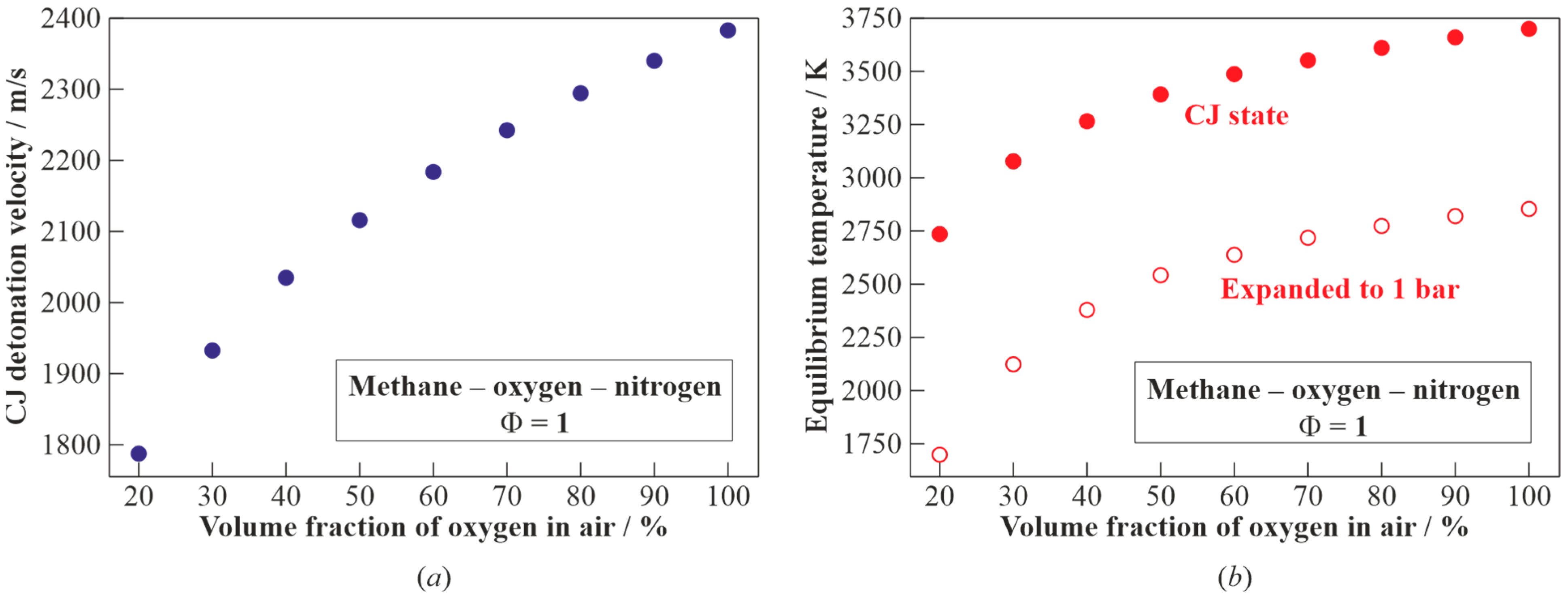
Figure 6 shows the calculated dependences of the CJ detonation velocity (
Figure 6a) and the temperature of the detonation products in the CJ state and after expansion to
= 1 bar (
Figure 6b) on the volume fraction of the oxygen in the air. When moving from the methane–oxygen to methane–air mixture, the detonation velocity
is seen to monotonically decrease from 2383 to 1805 m/s. The temperature of the detonation products in the CJ state decreases from 3703 to 2782 K, and the temperature of the detonation products expanded to
= 1 bar decreases from 2852 to 1750 K.
3.2. Gasification of WO by Detonation Products of the Stoichiometric Fuel–Oxygen Mixture
3.2.1. Model 1
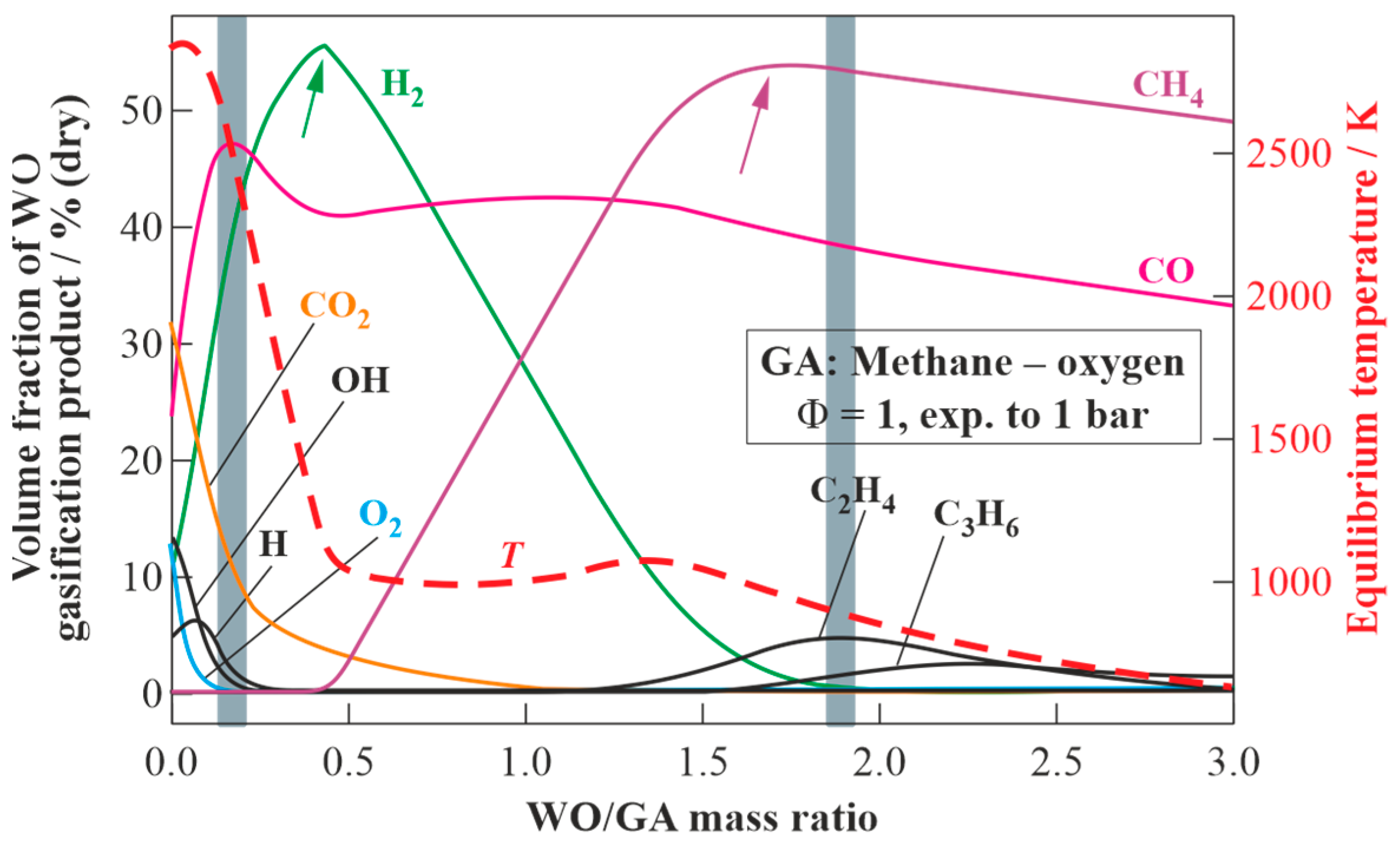
Figure 7 presents the equilibrium temperatures and compositions of the dry products of WO gasification in the detonation products of the stoichiometric methane–oxygen mixture expanded to
= 1 bar (see
Figure 3) as a function of the WO/GA mass ratio. As the target composition of dry gasification products, one can choose a composition with the maximum hydrogen content (syngas) or a composition with the maximum methane content (energy gas).
In the first case, a syngas with a ratio of H2/CO = 1.35 is obtained as a result of gasification by adding 0.45 kg of WO to 1 kg of GA. This syngas is characterized by the contents of H2 55.4 vol% (dry), CO 41 vol% (dry), CO2 3.4 vol% (dry), CH4 0.2 vol% (dry), temperature 1121 K, and lower heating value (LHV) 19.9 MJ/kg. If instead of the WO/GA mass ratio one considers the WO/fuel (methane) mass ratio, it turns out that with the help of 1 kg of CH4 and 4 kg of O2, it is feasible to gasify 2.2 kg of WO and obtain 7.2 kg of syngas with the composition specified above.
To obtain the second target composition with a methane content of 53.9 vol% (dry), it is necessary to gasify 1.73 kg of WO using 1 kg of GA. In addition to CH4, such energy gas contains CO (39.3 vol% (dry)), H2 (1.2 vol% (dry)), C2H4 (4 vol% (dry)), C2H2 (0.7 vol% (dry)), and C3H6 (0.8 vol% (dry)). The temperature and LHV of such energy gas are 952 K and 33.6 MJ/kg, respectively. If instead of the WO/GA mass ratio one uses the WO/fuel (methane) mass ratio, then it turns out that with the help of 1 kg of CH4 and 4 kg of O2 it is feasible to gasify 8.63 kg of WO and obtain 13.63 kg of energy gas with the composition specified above.
It is instructive to compare the results of the calculations in
Figure 7 with experimental data for the gasification of waste machine oil with the GA obtained by the pulsed detonations of the stoichiometric natural gas—oxygen mixture [
37]. Experiments in [
37] were conducted with a pulsed detonation frequency of 1 Hz. The pressure in the gasifier was slightly above atmospheric pressure, i.e.,
1 bar. The liquid WO was fed to the PDG either at the open end or inside the PDG.
Table 1 compares the results of the experiments with thermodynamic calculations in terms of the WO mass flow rate,
, the total mass flow rate of GA (fuel plus oxygen),
, the ratio of mass flow rates of WO and GA,
, the measured wall temperature of the gasifier,
, the calculated equilibrium gas temperature in the gasifier,
, and the contents of CO
2, CO, H
2, CH
4, O
2, and C
xH
y in the dry syngas (the numbers in parentheses correspond to calculations). Note that in the experiments, the local instantaneous temperatures of the GA in the gasifier exceeded 2800 K, so the gasification reactions proceeded in the wide range of temperatures between the wall temperature and GA temperature.
When analyzing the data in
Table 1, the following observations are worth mentioning. Firstly, the WO/GA mass ratio in the experiments [
37] varied from 0.75 to 1.18, which was considerably larger than the value of WO/GA = 0.45 ensuring the maximum content of H
2 in the produced syngas according to
Figure 7. Secondly, the measured wall temperature of the gasifier (=823–873 K) is seen to be 150–180 K less than the calculated equilibrium temperature of the gasification products (about 1000 K), which looks reasonable as the gasifier was not thermally insulated in the experiments. Thirdly, the ranges of the measured (36–43 vol% (dry)) and calculated (42–43 vol% (dry)) CO volume fractions, H
2 volume fractions (26–31 vol% (dry) vs. 20–42 vol% (dry)), and O
2 volume fractions (both approximately zero) in the produced syngas agree with some scatter but reasonably. Fourthly, the measured and calculated contents of CO
2, CH
4, and C
xH
y disagree significantly: on the one hand, the calculations considerably underestimate the contents of CO
2 (9–13 vol% (dry) in measurements vs. 1–2 vol% (dry) in calculations) and C
xH
y (6–11 vol% (dry) in measurements vs. 0 in calculations) and, on the other hand, the calculations considerably overestimate the content of CH
4 (10–13 vol% (dry) in measurements vs. 16–35 vol% (dry) in calculations).
Significant differences in the measured and calculated volume fractions of CO
2, CH
4, and C
xH
y in the produced syngas are likely caused by the highly inhomogeneous mixing and heating of WO with GA jets in the experiments. Note that the WO/GA mass ratio in the experiments is defined as the overall rather than local mass ratio, whereas in the thermodynamic calculations, both overall and local WO/GA mass ratios are the same. Since chemical reactions proceed at the local WO/GA mass ratio, one can conditionally imply that one part of WO is gasified at the local WO/GA mass ratio less than 0.45, whereas another part of WO is gasified at the local WO/GA mass ratio higher than 0.45. This implication is conditionally illustrated in
Figure 7 by two grey vertical bands. Obviously, the measured values of the CO
2, CO, H
2, CH
4, O
2, and C
xH
y volume fractions in
Table 1 can be obtained by averaging two different syngas compositions corresponding to these two conditional values of the local WO/GA mass ratio. As a matter of fact,
Figure 8 shows the schematic of the shock-induced fragmentation of four WO drops. Clearly, the local WO/GA mass ratio is different for the dense cores in the mist clouds behind the drops and for the loose zones near the edges of the clouds.
3.2.2. Model 2
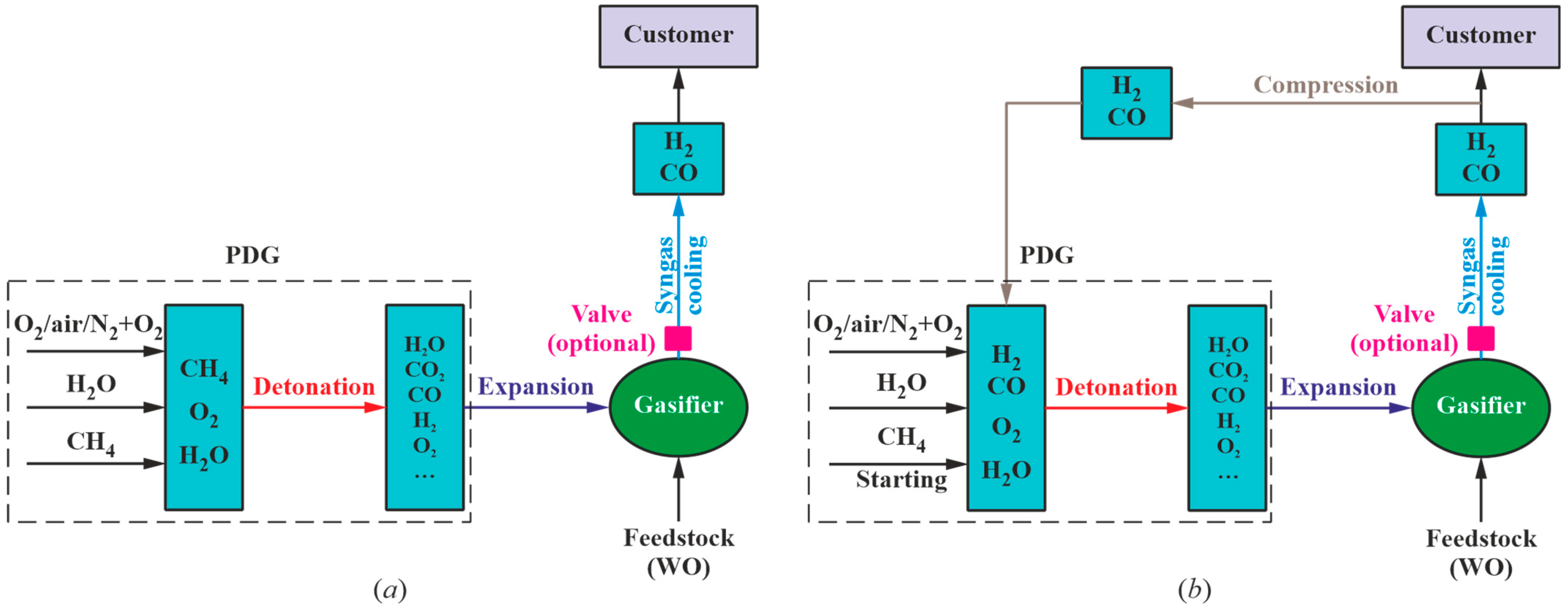
Model 2 implies the self-feeding of the PDG with the produced syngas. The self-feeding of the PDG is preceded by its operation on the starting fuel (methane). The composition of the syngas obtained by the detonation of the stoichiometric methane–oxygen mixture can be determined from
Figure 7. To determine the composition of the syngas obtained with PDG self-feeding, it is necessary to gradually replace the starting fuel (methane) in the PDG with dry syngas obtained as a result of WO gasification.
Table 2 shows the calculated parameters of the WO gasification process with one cycle (cycle 0) with the starting fuel (methane) and ten subsequent cycles (cycles 1 to 10) with PDG self-feeding with the stoichiometric mixture of the produced syngas with oxygen. Firstly, the detonation velocity
of the stoichiometric syngas–oxygen mixture exceeds 2082 m/s, which is only 14.5% less than the detonation velocity of the starting fuel (
2383 m/s). Secondly, by already the 8th–9th cycle the composition and temperature of the produced syngas are established: the addition of 0.37 kg of WO to 1 kg of GA results in the production of a syngas with a ratio of H
2/CO = 1.04, with a temperature of 1095 K, with a high content of H
2 (48.4 vol% (dry)) and CO (46.4 vol% (dry)), with a low content of CO
2 (4.8 vol% (dry)), and with negligible contents of C
2–C
3 hydrocarbons. The LHV of such syngas is 17.9 MJ/kg. Using 1 kg of such syngas and 1.28 kg of O
2, it is feasible to gasify 0.81 kg of WO and obtain 3.09 kg of the identical syngas, i.e., the conversion of 1 kg of WO in the GA requires 32.4% of the produced syngas.
3.3. Gasification of WO by Detonation Products of the Stoichiometric Fuel–Air Mixture
3.3.1. Model 1
It is interesting to determine the expected composition of syngas when replacing oxygen with air in the PDG. In this case, the composition and temperature of the GA for model 1 are determined from
Figure 5 (values at
bar).
Figure 9 presents the results of the calculations of the equilibrium states of the WO gasification products as a function of the WO/GA mass ratio. As the target composition of the dry gasification products, one can choose, e.g., a composition with the maximum hydrogen content (syngas) or a composition with the maximum methane content (energy gas). In the first case, when adding 0.09 kg of WO to 1 kg of GA, the gasification process results in a syngas with a ratio of H
2/CO = 1.7 with the contents of H
2 23.7 vol% (dry), CO 13.8 vol% (dry), CO
2 6.0 vol% (dry), N
2 55.5 vol% (dry), and CH
4 1.0 vol% (dry) with a temperature of 928 K and an LHV of 4.6 MJ/kg. If instead of the WO/GA mass ratio one uses the WO/fuel (methane) mass ratio, it turns out that with the help of 1 kg of CH
4 and 17.2 kg of air it is feasible to gasify 1.65 kg of WO and obtain 19.8 kg of syngas with the specified composition. The calculated detonation velocity of the stoichiometric syngas–air mixture is
= 1802 m/s, which is at the level of values realized in practice for the fuel–air mixtures of a number of hydrocarbon fuels. In the second case, using 1 kg of GA, it is possible to gasify 0.42 kg of WO to produce an energy gas containing CH
4 (32.0 vol% (dry)), CO (23.3 vol% (dry)), C
2H
4 (0.3 vol% (dry)), and N
2 (44.4 vol% (dry)) with a temperature of 763 K and an LHV of 13.6 MJ/kg.
3.3.2. Model 2
Model 2 implies the self-feeding of the PDG with the produced syngas. The self-feeding is preceded by PDG operation on starting fuel (methane). The composition of the syngas obtained by the detonation of the stoichiometric methane–air mixture can be determined from
Figure 9. To determine the composition of the syngas obtained with PDG self-feeding, it is necessary to gradually replace the starting fuel (methane) in the PDG with dry syngas produced by WO gasification. These manipulations can be accomplished by gradually replacing methane with the syngas of the resulting composition. Calculations show that the temperature and composition of the produced syngas are established only by the 14th–15th cycle: when adding 0.03 kg of WO to 1 kg of GA, gasification results in a syngas with a ratio of H
2/CO = 1.76 and with a temperature of 785 K (the contents of H
2 7.1 vol% (dry), CO 4.0 vol% (dry), CO
2 12.9 vol% (dry), CH
4 1.7 vol% (dry), and N
2 74.3 vol% (dry)). The LHV of such syngas is 1.5 MJ/kg, and the calculated detonation velocity of the stoichiometric syngas–air mixture is below 1300 m/s, which is over 40% less than the detonation velocity of the starting fuel (=1805 m/s). Since such a detonation velocity looks too low for organizing a reliable detonation process, one can expect that the gasification process according to model 2 is not feasible in practice.
3.4. Gasification of WO by Detonation Products of the Stoichiometric Fuel–Oxygen-Enriched Air Mixture
3.4.1. Model 1
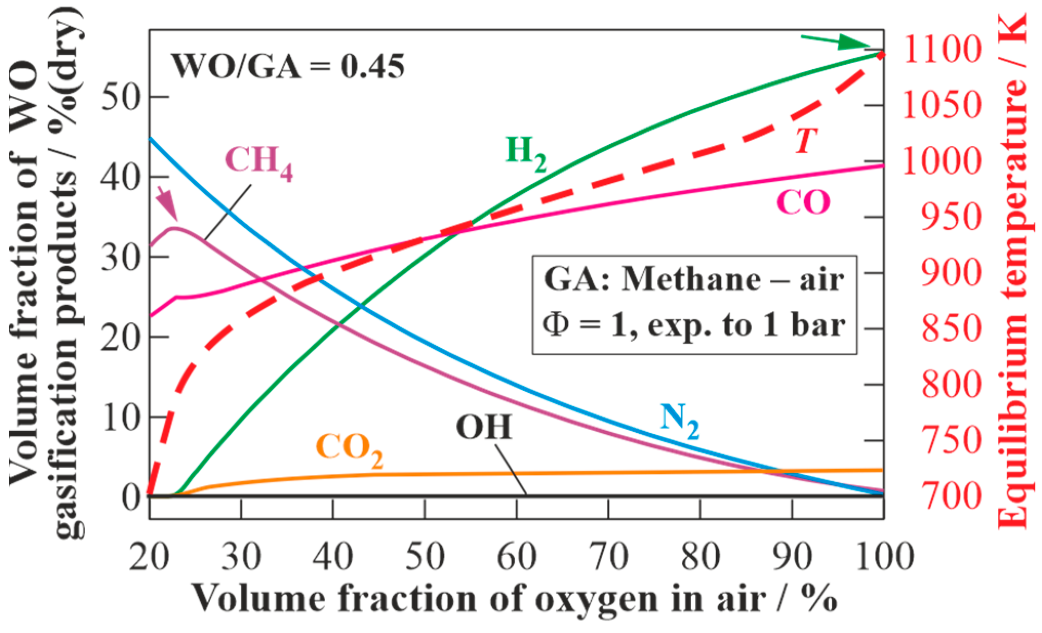
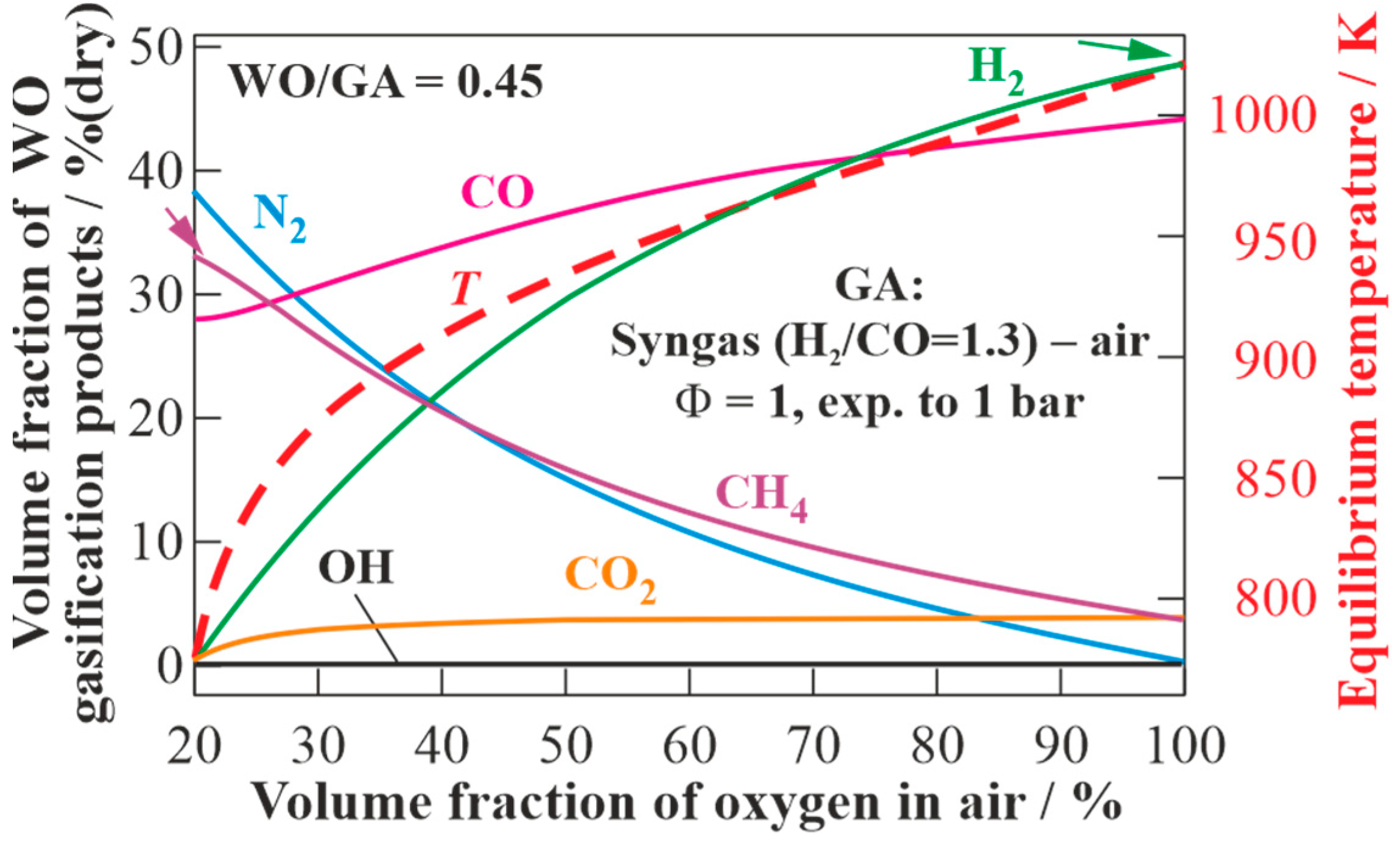
Figure 10 presents the results of the calculations of the equilibrium states of the dry products of WO gasification using GA, obtained by the detonation of the stoichiometric methane–oxygen–nitrogen mixture with different concentrations of oxygen in the air, but at a fixed WO/GA mass ratio of 0.45 (see
Figure 7). With increasing oxygen concentration in the air, the contents of H
2, CO, and CO
2 in the produced syngas monotonically increase, and the content of CH
4 monotonically decreases (at O
2 concentration in the air above 25 vol% (dry)). As the target composition of the dry gasification products, one can choose, e.g., a composition with the maximum content of H
2 (syngas) or a composition with the maximum content of CH
4 (energy gas). In
Figure 9, these compositions are shown by arrows. In the first case, the maximum volume fraction of H
2 (55.2 vol% (dry)) is achieved when pure oxygen is used as GA. The LHV of such syngas is 19.9 MJ/kg. An energy gas with the maximum volume fraction of CH
4 (33.6 vol% (dry)) is obtained with the content of O
2 in the air of 23 vol% (dry). The LHV of such energy gas is 17.9 MJ/kg.
3.4.2. Model 2
Figure 11 presents the results of the calculations of the equilibrium states of the dry gasification products of WO using GA, obtained by the detonation of the stoichiometric syngas (H
2/CO = 1.3)–oxygen–nitrogen mixture with different oxygen concentrations in the air, but at a fixed WO/GA mass ratio of 0.45 (see
Figure 7). With increasing oxygen concentration in the air, the contents of H
2 and CO in the produced syngas monotonically increase, and the content of CH
4 monotonically decreases. As the target composition of the dry gasification products, one can choose, e.g., a composition with the maximum content of H
2 (syngas) or a composition with the maximum content of CH
4 (energy gas). In the first case, the maximum content of H
2 (51 vol% (dry)) is achieved when using pure oxygen as GA. The LHV of such syngas is 16.7 MJ/kg. In the second case, an energy gas with the maximum content of CH
4 (34 vol% (dry)) is obtained with an oxygen concentration in the air of 21 vol% (dry). The LHV of such energy gas is 20.3 MJ/kg.
3.5. Simple Estimates
Thus, when using methane as fuel and oxygen as oxidizer for PDG and operating the gasifier at
= 1 bar, calculations with model 1 show that using 1 kg of CH
4 and 4 kg of O
2, it is feasible to gasify 2.2 kg of WO and obtain 7.2 kg of syngas with an H
2 content of 55.4 vol% (dry) and CO content of 41 vol% (dry) (with an H
2/CO ratio of 1.35) and an LHV of 19.9 MJ/kg. If the resulting syngas is used as fuel for the PDG according to model 2, then the portion of the syngas for PDG self-feeding will be 32.4%, i.e., approximately one-third, and the remaining two-thirds of the produced syngas can be delivered to a customer.
Table 3 shows the calculated H
2/CO ratio and composition of the dry syngas obtained by model 2.
The results of the thermodynamic calculations presented in
Table 3 can be compared with simple estimates based on the overall reaction of the high-temperature gasification of C
16H
34 by steam and carbon dioxide with the complete conversion of carbon into CO:
It is easy to show that the stoichiometric coefficients of such a reaction are
= 0.485 and
= 1.485. It follows from Equation (1) that with the help of 1 kg of GA it is feasible to gasify 0.46 kg of WO and obtain a syngas with a ratio of H
2/CO = 1.06 with a hydrogen content of 51.5 vol% (dry) and CO content of 48.5 vol% (dry). These results are compared with the results of the thermodynamic calculations in the last line of
Table 3. The values of the H
2/CO ratio and syngas composition obtained from Equation (1) are in reasonable agreement with the thermodynamic calculations using model 2. Equation (1) slightly overestimates the quality of the produced syngas. The reason for this overestimation is that Equation (1) assumes the complete conversion of carbon into CO, which implies a gasification temperature exceeding 1500 K. From now on, the term “gasification temperature” implies the equilibrium temperature of the gasification products. However, the thermodynamic calculations show a relatively low gasification temperature of 1095 K and the incomplete conversion of carbon into CO: the syngas in model 2 contains 4.8 vol% (dry) CO
2 and 0.3 vol% (dry) CH
4.
To enhance the carbon conversion efficiency, one can increase the gasification temperature. The gasification temperature in models 1 and 2 can be increased by increasing the gasification pressure
in the gasifier. This can be done by making a provision for a pressure relief valve at the gasifier outlet (see
Figure 2). The valve could vent the gasifier after each detonation pulse when the pressure exceeds a certain preset value. In this case, the CJ detonation products will expand to the gasifier with the growing backpressure. Thus, according to
Figure 3, when the gasification process of WO in model 1 is carried out at an intermediate pressure
, the gasification temperature increases from 2852 to 3700 K. However, on the one hand, an increase in the gasification pressure
leads to the variation in GA composition: the concentrations of H
2O and CO
2 in the GA decrease from 48 to 36 vol% and from 17 to 10 vol%, respectively, whereas the concentrations of CO and H
2 increase from 12 to 17 vol% and from 6 to 8 vol%, respectively. As for the O, H, and OH radicals and molecular oxygen O
2, their concentrations increase from 10 to 21 vol% and from 7 to 8 vol%, respectively. On the other hand, the composition of the GA can be controlled by diluting the combustible mixture in the PDG with low-temperature steam. Thus, according to
Figure 4, with an increase in the steam dilution degree of the stoichiometric methane–oxygen mixture from 0 to 40 vol%, the temperature of the detonation products in model 1 decreases from 2850 to 2450 K, but the content of steam in the GA in model 1 increases from 48 to 74 vol%, whereas the content of CO
2 remains approximately at the same level of 17–16 vol%, respectively. The addition of steam to the stoichiometric methane–oxygen mixture in model 1 increases the content of H
2 in the produced syngas from 55.4 to 62.8 vol% (dry) and reduces the content of CO in model 1 from 41.2 to 18.6 vol% (dry), thus changing the H
2/CO ratio in the resulting syngas from 1.3 to 3.4.
Let us now estimate the amount of the produced syngas utilized for PDG self-feeding. To produce the GA entering the left side of Equation (1), it is necessary to spend some amounts of the produced syngas and oxygen, which can be determined from the following reaction equation:
It follows from Equation (2) that for producing 1 kg of GA it is necessary to consume 0.48 kg of syngas and 0.52 kg of oxygen. Using the results of the analysis of Equation (1), one finds that for the gasification of 0.46 kg of WO it is necessary to consume 0.48 kg of syngas and 0.52 kg of oxygen. As a result of gasification, 0.46 + 0.48 + 0.52 = 1.46 kg of syngas is obtained, i.e., 32.8% of the produced syngas is used for PDG self-feeding. This result is in good agreement with the thermodynamic calculation for model 2, in which 32.4% of the produced syngas is consumed in PDG self-feeding. This means that the approach presented herein can be used for the simple estimates of self-feeding needs.
If one considers energy gas as the target product of WO gasification according to model 1, then with the help of 1 kg of CH4 and 4 kg of O2 it is feasible to gasify 8.63 of WO and obtain 13.63 kg of energy gas with a content of CH4 of 53.9 vol% (dry), CO 39.3 vol% (dry), H2 1.2 vol% (dry), C2H4 4 vol% (dry), C2H2 0.7 vol% (dry), C3H6 0.8 vol% (dry), etc. The LHV of such energy gas reaches 33.7 MJ/kg.
When using methane as fuel and air as oxidizer for PDG, calculations with model 1 show that using 1 kg of methane and 17.2 kg of air, it is feasible to gasify 1.65 kg of WO and obtain 19.8 kg of syngas with the contents of H2 23.7 vol% (dry) and CO 13.8 vol% (dry) with H2/CO = 1.7, an LHV of 4.6 MJ/kg, and a gasification temperature of 928 K.
By increasing the backpressure in the gasifier and enriching the air with oxygen, it looks possible to implement in practice the process of WO gasification according to model 2. On the one hand, according to
Figure 5, when operating a PDG on the stoichiometric methane–air mixture at
= 1 bar, the increase in the gasification pressure
from 1 to 5 bar will lead to an increase in the gasification temperature from 1750 to 2300 K. On the other hand, according to
Figure 6, the enrichment of air with oxygen leads to the monotonic increase in the detonation velocity of the stoichiometric methane–oxygen–nitrogen mixture from 1805 to 2382 m/s and an increase in the CJ temperature of the detonation products from 2782 to 3700 K. With an increase in the backpressure in the gasifier and/or oxygen content in the air, the content of H
2 and CO in the produced syngas in model 1 monotonically increases. It can be expected that at certain values of backpressure in the gasifier and/or oxygen content in the air, WO gasification with PDG self-feeding with the produced syngas will become practically feasible.
Let us now estimate the amount of produced syngas that can be used for the self-feeding of the PDG operating on the fuel–air mixture implying the complete conversion of carbon into CO. In this case, the overall reactions of Equations (1) and (2) will take the following form:
Firstly, it follows from Equation (3) that the gasification of 1 kg of WO with 7.7 kg of GA will produce 8.7 kg of syngas diluted with nitrogen. The syngas will have H2/CO = 1.06 and the contents of H2, CO, and N2 will be 26.9, 25.4, and 47.7 vol% (dry), respectively. Secondly, it follows from Equations (3) and (4) that for producing 1 kg of GA one needs to consume 0.369 kg of syngas and 0.631 kg of air, i.e., 100 × 7.7 × 0.369/8.7 = 32.7% is consumed on PDG self-feeding with the produced syngas. This result agrees satisfactorily with the results of the thermodynamic calculations using model 2 and the estimates based on Equations (1) and (2) for the case when the PDG operates on the fuel–oxygen mixture (32.4% and 32.8%, respectively).
If one considers energy gas as the target product of WO gasification by the detonation products of the stoichiometric methane–air mixture at = 1 bar, then according to model 1 with the help of 1 kg of GA it is feasible to gasify 0.45 kg of WO and obtain an energy gas with the contents of CH4 32 vol% (dry), CO 23.3 vol% (dry), N2 44.4 vol% (dry), and C2H4 0.3 vol% (dry) with a gasification temperature of 763 K and an LHV of 13.6 MJ/kg.
