Article

Online Estimation of Three-Phase Induction Motor Parameters Using an Extended Kalman Filter for Energy Saving

1
The National Electronics and Computer Technology Center, Pathum Thani 12120, Thailand
2
School of Electrical Engineering, Institute of Engineering, Suranaree University of Technology, Nakhon Ratchasima 30000, Thailand
3
School of Mathematics, Institute of Science, Suranaree University of Technology, Nakhon Ratchasima 30000, Thailand
*
Author to whom correspondence should be addressed.
Energies 2024, 17(9), 2115; https://doi.org/10.3390/en17092115
Submission received: 13 March 2024 / Revised: 25 April 2024 / Accepted: 27 April 2024 / Published: 28 April 2024
(This article belongs to the Section F: Electrical Engineering)

Abstract

:
In this paper, the online estimation of three-phase induction motor parameters using an extended Kalman filter for energy saving is proposed. The optimal value of the stator current on the d-axis is calculated to obtain the minimum power loss. Accurate motor parameters are required to calculate the optimal stator current value for energy saving. Hence, to estimate motor parameters in real time, an online estimator known as the extended Kalman filter is applied. The energy consumption results for the motor using the proposed approach (estimated parameters with extended Kalman filter) are compared with those obtained using the conventional approach and energy saving (fixed parameters without parameter estimation) approach. As revealed by the comparison results from implementation in a laboratory, the proposed approach can provide minimum power losses for the three-phase induction motor drive, and the maximum energy-saving percentage is 60.18% compared with using the conventional drive approach.

1. Introduction

The three-phase induction motor (IM) is widely used in various industries, especially in electric vehicle (EV) systems, because of its low cost, low maintenance, and high efficiency [1,2,3]. Energy saving in electrical systems has become a significant issue, especially in respect of electric motors, because energy saving in an EV system can allow greater driving distances and help to minimize electricity costs from battery charging. Therefore, in this paper, an energy-saving method for a three-phase IM is proposed. In previous works, energy-saving methods such as frequency control [4,5], flux control [6,7,8,9], optimal balance of the stator current on the d-axis ( i ds ) and the q-axis ( i qs ) [10,11,12,13] and i ds control [14] were reported. In the present work, the minimum power loss ( P loss ) is computed using the partial derivative of P loss with respect to i ds that is equal to 0. Using this method, the optimal i ds value for energy saving can be easily determined. However, accurate parameters in the P loss equation are important for optimal i ds calculation. In the methods described in previous studies, the motor parameters for calculation are held constant. Normally, motor parameters change in different operating conditions. Thus, online estimation for updated parameters in real time is necessary. In the literature, to improve the performance of the controller in a drive system, the parameter estimation of IM is a common aim [15,16,17]. However, the performance improvement of the controller is not the goal of this study; instead, the focus is on parameter estimation for energy saving in respect of the three-phase IM with the aim of reducing the electrical energy consumption. Estimation methods identified in the literature survey include constrained optimization [18], the least-squares method [19,20,21,22], the extended Kalman filter (EKF) [23,24,25,26,27,28,29] and artificial intelligence (AI) techniques [30,31,32]. The advantages of the EKF are that it can be used on a multi-input and multi-output system and it is suitable for a time-varying system. Additionally, it has fast convergence even if the operating points are changed [24]. Conversely, the condition of the constrained optimization method is complicated, the least-squares method is sensitive to disturbance signals and has slow convergence [19] and AI techniques are complex, requiring significant time for computation [33,34]. Therefore, in this work, the EKF is deemed suitable for parameter estimation.
The proposed P loss equation in this paper comprises the motor parameters and power loss parameters. As suggested by the literature survey, the power loss parameters cannot be directly measured. Therefore, the adaptive tabu search (ATS) technique [35] is used to off-line search for the accurate power loss parameters, whereas the motor parameters are estimated online using the EKF. The online estimation of motor parameters using the EKF with an energy-saving approach is the new idea proposed in this paper.
It is well known that vector control is widely used for three-phase IM drive systems. Indirect vector control has been chosen for this work because this technique can approximate the rotor flux using motor parameters [36,37]. Conversely, direct vector control uses rotor flux measurement in the control process.
The comparison results from the implementation using three IM drive approaches are shown in this paper. The proposed method with parameter estimation provides the best results in terms of the electric energy consumption of the three-phase IM drive. Compared with the conventional drive in the same condition, the input power consumption of the motor drive system using the energy-saving approach proposed in this paper is decreased.
The paper is structured as follows. Section 2 describes the power loss equation and motor testing. In Section 3, the extended Kalman filter is presented. Section 4 explains the experimental results of the energy saving and presents the discussion. Section 5 summarizes the proposed method for energy saving and presents conclusions.

2. Power Loss Equation and Motor Testing

In this section, the power loss equation of the three-phase IM is presented. Three assumptions are made to simplify the IM loss model. Firstly, the leakage inductances ( L l s , L l r ) can be neglected because these parameters have small values compared with the magnetizing inductance ( L m ). Secondly, the rotor linkage flux ( λ r ) is defined on the d-axis. Therefore, the rotor linkage on the q-axis ( λ qr ) is zero. Thirdly, the voltage across the magnetizing inductance on the d-axis can be set to zero. Thus, the simple model including losses of the IM can be depicted as shown in Figure 1. This model is used to calculate the total power losses of the IM in this paper. The considered power losses comprise the stator copper loss ( P scl ), the rotor copper loss ( P rcl ), the iron loss ( P i ) and the stray loss ( P stray ). Hence, the power loss of the three-phase IM can be calculated using Equation (1).
P l o s s = P s c l + P r c l + P i + P s t r a y = R s ( i d s 2 + i q s 2 ) + R r i q r 2 + R q f s i q f s 2 + R q f r i q f r 2 + R s t r a y i q r 2
In this paper, a proposed energy-saving algorithm using indirect field-oriented control is presented. The minimum value of P loss can be obtained when the partial derivative of P loss with respect to i ds * equal to 0. Therefore, i ds is the significant value concerned in this paper and Equation (1) can be rewritten in the form of i ds . The power loss equation of the three-phase IM for energy saving is shown in Equation (2) [38].
P l o s s = R d i d s 2 + R q ( T L K t i d s ) 2 R d q T L K t
where
K t = 3 2 Z p L m
R d = R s + ( R q f r ( ω r L m ) 2 ( R r + R s t r a y ) ( R r + R s t r a y + R q f r ) 2 ( R q f s + R R ) 2 ( R r + R s t r a y + R q f r ) ) + ( R R ( ω r L m ) 2 R q f s ( R q f s + R R ) ( R R ( R q f s + R R ) 2 ) ) + ( ω r L m ) 2 R q f s
R q = R s + ( R q f r R q f s 2 ( R r + R s t r a y ) ( R r + R s t r a y + R q f r ) 2 ( R q f s + R R ) 2 ( R r + R s t r a y + R q f r ) ) + R R 2 R q f s ( R q f s + R R ) 2
R d q = ( 2 R q f s R q f r ω r L m ( R r + R s t r a y ) ( R r + R s t r a y + R q f r ) 2 ( R q f s + R R ) 2 ( R r + R s t r a y + R q f r ) ) + ( 2 R R ω r L m ( R q f s + R R ) ( R R R q f s + R R 1 ) )
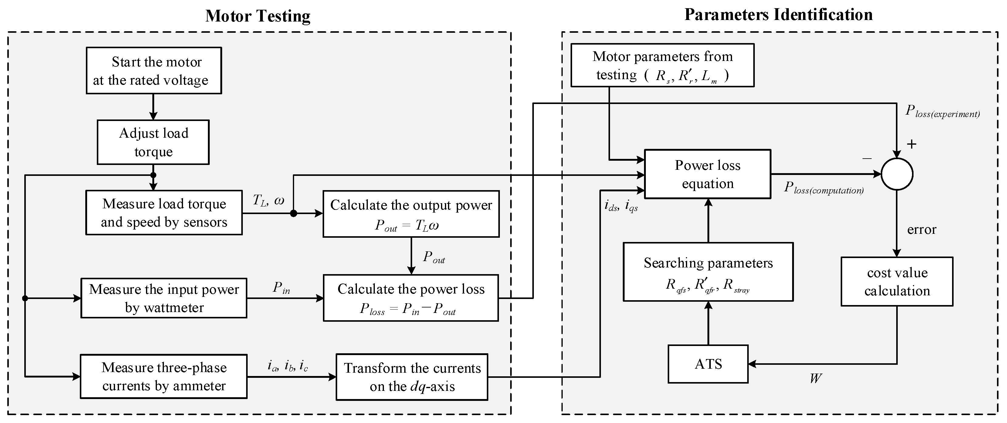
The power loss parameters ( R q f s , R q f r , R s t r a y ) cannot be measured. Thus, these parameters are identified off-line using the adaptive tabu search (ATS) technique [38]. The details for power loss parameter identification using the ATS method can be summarized as shown in Figure 2.
In Figure 2, the cost value (W) can be calculated using Equation (3). This equation is the root mean squared error between the power loss values from experiment ( P loss ( experiment ) ) and computation ( P loss ( computation ) ) as given in Equation (4).
W = e r r o r 2 n
error = P loss ( experiment ) P loss ( computation )
According to Figure 2, the ATS process is used to search the R q f s , R q f r and R s t r a y parameters. The new parameters from ATS searching are used to calculate the power loss ( P loss ( computation ) ). The new P loss ( computation ) value is subtracted from P loss ( experiment ) again. The ATS process is operated to tune the R q f s , R q f r and R s t r a y values until the minimum W value can be achieved. More details about the ATS method for identifying power loss parameters can be found in the prior work [38].
The rating of the motor used in this paper is 0.5 hp, V L - L = 380 V, I L   = 1.1 A and pole pairs ( Z p ) = 2. The motor parameters are R s = 25.13 Ω, R r = 20.79 Ω, L m = 0.9672 H and L ls = L lr = 0.0866 H. These parameters can be determined from conventional testing (locked rotor test and no-load test). The details of the conventional testing are as follows.
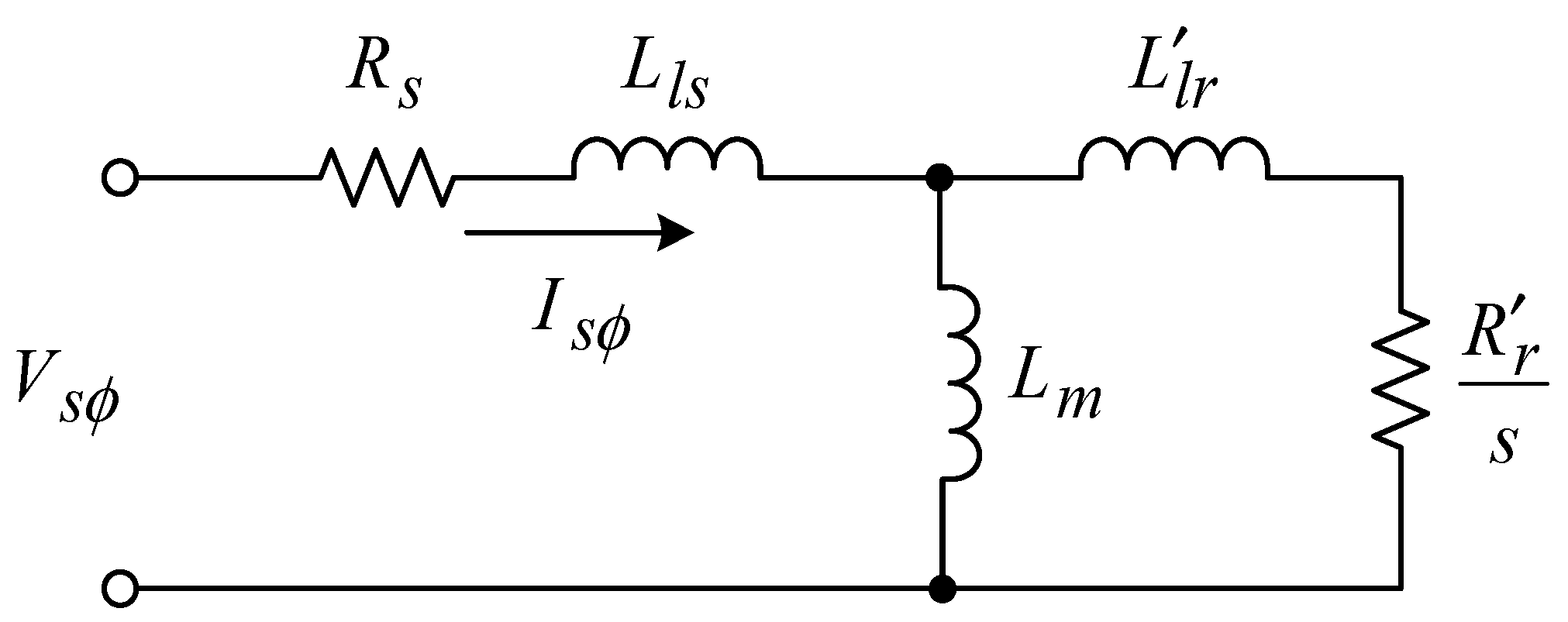
The equivalent circuit per phase of the motor is shown in Figure 3. There are three steps in the motor testing procedure for finding the motor parameters.
Step 1: Measure the stator resistance directly using an ohmmeter. The results from this measurement are given in Table 1.
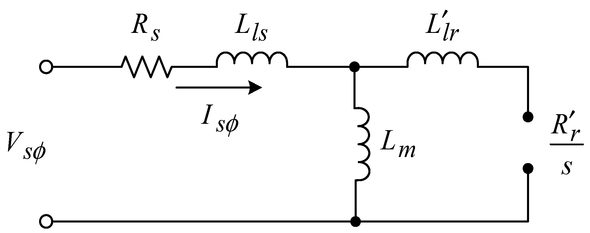
Step 2: This step involves the no-load test of the motor. The slip is approximately zero ( s 0 ) in this step. The equivalent circuit for the no-load test is shown in Figure 4. L ls and L lr are the stator and rotor leakage inductances, respectively. L m is the magnetizing inductance of the motor. R s and R r are the stator and rotor resistances, respectively. For the no-load test in this step, the stator and the magnetizing inductances are calculated using Equation (5). The phase voltage and current from the no-load testing are equal to 219.5 V and 0.663 A, respectively. Thus, L ls + L m is equal to 1.0538 H.
L l s + L m V s ϕ I s ϕ 2 π f
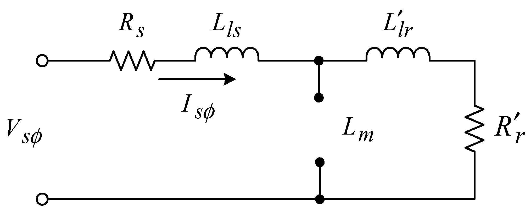
Step 3: This step involves the locked-rotor test. The slip is equal to one (s = 1) in this step. The equivalent circuit for the locked-rotor test is shown in Figure 5. The value of L m is much greater than L lr . Therefore, L m is an open circuit. Equations (6) and (7) are used for the calculation of the equivalent resistance and reactance, respectively. The results for the locked-rotor test and the values calculated using Equations (6) and (7) are shown in Table 2.
R e q = R s + R r = V s ϕ I s ϕ cos θ
X e q = X l s + X r = V s ϕ I s ϕ sin θ
From Equation (6), we substitute R s and R eq equal to 25.13 Ω and 45.92 Ω, respectively. Therefore, the rotor resistance ( R r ) is equal to 20.79 Ω. From the equivalent reactance in Table 2, the equivalent inductance can be calculated using Equation (8). In this work, the stator leakage reactance is equal to the rotor leakage reactance. Thus, L ls and L lr are equal to 0.0866 H, as calculated using Equation (9). As shown in Equation (10), L m is equal to 0.9672 H from Equation (5).
L e q = X e q 2 π f = X l s + X r 2 π f = 0.173   H
L l s = L l r = 0.173 2 = 0 . 0866   H
L m = 1.0538 L l s = 0.9672   H

3. Extended Kalman Filter

3.1. Extended Kalman Filter Algorithm

The state equation of the three-phase IM for estimation is shown in Equation (11). The equation is considered to be in the synchronous reference frame. The state variables are the stator currents on the dq-axis ( i ds , i qs ) and the rotor fluxes on the dq-axis ( λ dr , λ qr ).
d x ( t ) d t = Ax ( t ) + Bu ( t )
where
  • x = [ i d s i q s λ d r λ q r ] T
A = [ ( R s σ L s + R r L m 2 σ L s L r 2 ) ω s R r L m σ L s L r 2 ω r L m σ L s L r ω s ( R s σ L s + R r L m 2 σ L s L r 2 ) ω r L m σ L s L r R r L m σ L s L r 2 R r L m L r 0 R r L r ω s l 0 R r L m L r ω s l R r L r ] B = [ 1 σ L s 0 0 1 σ L s 0 0 0 0 ] , u = [ v d s v q s ]
Equation (11) is the continuous state model. The forward Euler method is utilized to transform the continuous model into a discrete model. Therefore, the discrete state model of the three-phase IM is shown in Equation (12), where A(k) = I + A T s , B(k) = B T s , u(k) = [ v ds ( k ) v qs ( k ) ] T , x(k) = [ i ds ( k ) i qs ( k )   λ dr ( k ) λ qr ( k ) ] T and T s is the sampling time.
x ( k + 1 ) = A ( k ) x ( k ) + B ( k ) u ( k )
In this paper, the motor speed and the motor parameters are estimated. Thus, these values are included as additional state variables [27,29]. The motor parameters in the model are R s , R r , L ls , L lr and L m . However, L ls and L lr can be neglected because these parameter values are smaller than L m . Hence, the estimated parameters can be presented as per Equation (13).
( k ) = [ ω r ( k ) R s ( k ) R r ( k ) L m ( k ) ] T
Therefore, the extended state model of the three-phase IM for estimation is shown in Equation (14).
x e ( k + 1 ) = A e ( ( k ) ) x e ( k ) + B e ( ( k ) ) u ( k )
where x e k = [ i ds k i qs k λ dr k λ qr k ω r k R s k R r k L m k ]T
A e ( ( k ) ) = [ A ( ( k ) ) 0 0 I ] , B e ( ( k ) ) = [ B ( ( k ) ) 0 ]
From Equation (14), A ( Π ( k ) ) and B ( Π ( k ) ) comprise the estimated values of the speed and parameters. Then, the extended model in Equation (14) is the nonlinear model. This can be written as per Equation (15) and the matrix f ( x e ( k ) , u ( k ) , Π ( k ) ) is shown in Equation (19).
x e ( k + 1 ) = f ( x e ( k ) , u ( k ) , ( k ) )
The measurement equation of the motor for the estimation is given by Equation (16). z ( k + 1 ) and H are defined by Equations (17) and (18), respectively.
z ( k + 1 ) = Hx e ( k + 1 )
z ( k + 1 ) = [ i d s ( k + 1 ) i q s ( k + 1 ) ω r ( k + 1 ) ] T
H = [ 1 0 0 0 0 0 0 0 0 1 0 0 0 0 0 0 0 0 0 0 1 0 0 0 ]
f ( x e ( k ) , u ( k ) , ( k ) = [ ( 1 ( R s ( k ) σ ( k ) L s + R r ( k ) L m 2 ( k ) σ ( k ) L s L r 2 ) T s ) i d s ( k ) + ω s ( k ) T s i q s ( k ) + R r ( k ) L m ( k ) σ ( k ) L s L r 2 T s λ d r ( k ) + ω r ( k ) L m ( k ) σ ( k ) L s L r T s λ q r ( k ) + 1 σ ( k ) L s T s v d s ( k ) ω s ( k ) T s i d s ( k ) + ( 1 ( R s ( k ) σ ( k ) L s + R r ( k ) L m 2 ( k ) σ ( k ) L s L r 2 ) T s ) i q s ( k ) ω r ( k ) L m ( k ) σ ( k ) L s L r T s λ d r ( k ) + R r ( k ) L m ( k ) σ ( k ) L s L r 2 T s λ q r ( k ) + 1 σ ( k ) L s T s v q s ( k ) R r ( k ) L m ( k ) L r T s i d s ( k ) + ( 1 R r ( k ) L r T s ) λ d r ( k ) + ω s l ( k ) T s λ q r ( k ) R r ( k ) L m ( k ) L r T s i q s ( k ) ω s l ( k ) T s λ d r ( k ) + ( 1 R r ( k ) L r T s ) λ q r ( k ) ω r ( k ) R s ( k ) R r ( k ) L m ( k ) ]
The extended state model of the three-phase IM in Equation (15) is nonlinear [39,40]. Thus, the nonlinear estimator is applied to this problem. The extended Kalman filter (EKF) is the nonlinear extension of the Kalman filter, and this method is widely used for nonlinear estimation [23].
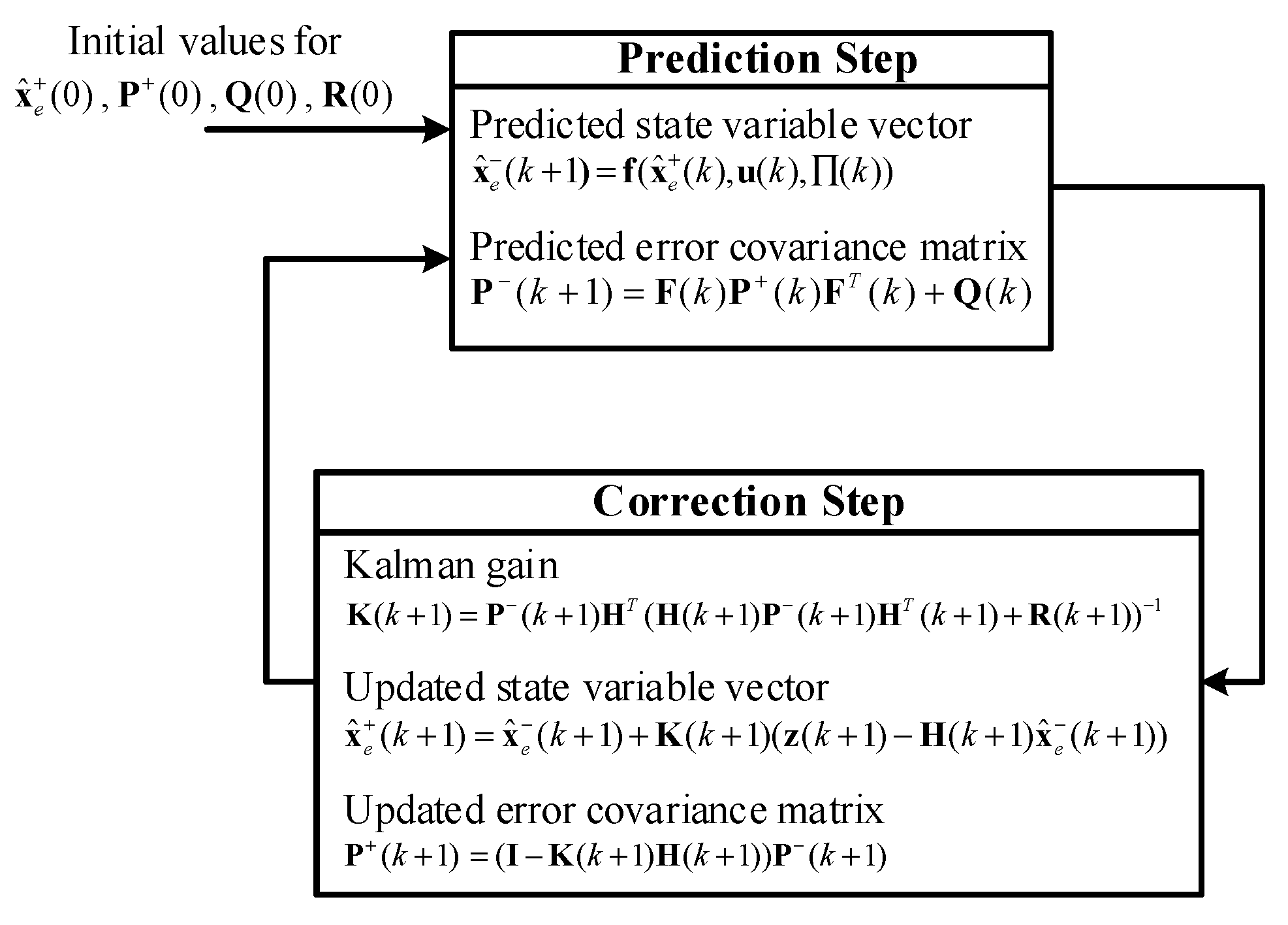
Calculation of the EKF comprises two steps, namely, the prediction step and the correction step. In the prediction step, the predicted state variable vector and the predicted error covariance matrix at time k+1 are computed using the data at time k. Next, the correction step calculates the updated state variable vector and the updated error covariance matrix using the data from the prediction step and the measurement. The values from the correction step become the data at time k for the prediction step calculation in the next round [41].
The system model and the measurement model with noise for the online estimation via EKF can be described by Equations (20) and (21), respectively. From these equations, the definition and dimension of vectors and matrices in the models are shown in Table 3.
x e ( k + 1 ) = f ( x e ( k ) , u ( k ) , ( k ) ) + w ( k )
z ( k + 1 ) = Hx e ( k + 1 ) + v ( k + 1 )
For the initial state variable ( x e 0 ), its mean value and error covariance matrix are x ^ e + ( 0 ) = E [ x e ( 0 ) ] and P + 0 = E [ x ~ e 0 x ~ e T 0 ] , respectively. E [ x e ] is the expected value of x e or the mean value of x e , and the estimation error can be calculated using x ~ e 0 = x e 0 x ^ e + ( 0 ) .
In this paper, the superscript ( ) indicates the a priori calculated values and ( + ) indicates the a posteriori calculated values. The assumptions for w ( k ) and v ( k ) used in deriving the Kalman filter can be found in [42].
The equations and the calculation process of the Kalman filter can be explained as follows.
The prediction step
The predicted state variable vector ( x ^ e ( k + 1 ) ) and the predicted error covariance matrix ( P ( k + 1 ) ) can be calculated using Equations (22) and (23), respectively.
x ^ e ( k + 1 ) = f ( x ^ e + ( k ) , u k , Π ( k ) )
P 0 k + 1 = F k P + k F T k + Q ( k )
Because Equation (22) is a nonlinear model, the first-order Taylor series is used to linearize this model [43]. Therefore, the state transition matrix is defined by Equation (24).
F ( k ) = f ( x e ( k ) , u ( k ) , ( k ) ) x e ( k ) | x e ( k ) = x ^ e + ( k )
From Equations (22) and (23), x ^ e + ( k ) and P + ( k ) are the updated state variable and the updated error covariance matrix at time k, respectively. These values can be determined using x ^ e + ( k ) = E [ x e ( k ) ] and P + ( k ) = E [ x ~ e + ( k ) x ~ e + T ( k ) ] , and the a posteriori estimation error can be calculated using x ~ e + ( k ) = x e ( k ) x ^ e + ( k ) .
The correction step
The updated state variable vector ( x ^ e + ( k + 1 ) ) and the updated error covariance matrix ( P + ( k + 1 ) ) can be calculated using Equations (25) and (26), respectively.
x ^ e + ( k + 1 ) = x ^ e ( k + 1 ) + K ( k + 1 ) ( z ( k + 1 ) H ( k + 1 ) x ^ e ( k + 1 ) )
P + ( k + 1 ) = ( I K ( k + 1 ) H ( k + 1 ) ) P ( k + 1 )
In the above equations, K ( k + 1 ) is the Kalman gain, which is calculated using Equation (27).
K ( k + 1 ) = P ( k + 1 ) H T ( k + 1 ) ( H ( k + 1 ) P ( k + 1 ) H T ( k + 1 ) + R ( k + 1 ) ) 1
Figure 6 illustrates the process of the EKF as described in this section and the calculation process. It is well known that the motor parameters change in different operating conditions. Thus, the EKF algorithm is applied to estimate these parameters online in real time. Hence, the initial state variables vector for the EKF computation is defined using the values of the motor parameters from conventional testing.
The initial values for the EKF calculation are set to the following values.
The initial state variables vector:
x ^ e (0) = [0 0 0 0 0 25.13 20.79 0.9672]T
The error covariance matrix:
P(0) = diag[1e − 2 1e − 2 1e − 4 1e − 4 1e − 2 1e − 2 1e − 1 1e − 3]
The system noise covariance matrix:
Q(0) = diag[1e − 2 1e − 2 1e−4 1e − 4 1e − 1 1e − 1 1e − 1 1e − 3]
The measurement noise covariance matrix:
R(0) = diag[1e − 4 1e − 4 1e − 4]
The initial values of the covariance matrices (P, Q, R) indicate the convergence speed of the estimation [17]. Moreover, changing values of the matrices Q and R affect both the transient and steady-state operation of the estimator [28]. In the method described in this paper, the selection of these initial values uses trial and error [26,28,39] by observing the simulation result using the hardware-in-the-loop (HIL) technique. This technique involves simulation using the Simulink program with a DSP board via MATLAB software (https://www.mathworks.com/products/matlab.html). The considered system is simulated using Simulink, and the estimation process of the EKF is implemented on the DSP board. The HIL technique can provide a simulation result that is nearly as accurate as the result from hardware implementation.

3.2. Convergence Analysis of the Extended Kalman Filter

Using the Lyapunov theorem [44], the convergence of the EKF can be analyzed to verify the Lyapunov function of the considered system ( V ( x ) ). If V ( x ) follows the Lyapunov theorem, the considered system is stable and it can converge to the equilibrium point. In the Lyapunov theorem, V ( x ) is a positive definite function ( V ( 0 ) = 0 and V ( x ) > 0 ,   x 0 ) and V ( x ) is a negative semi-definite function ( V ( x ) 0 for all x ).
V + ( k + 1 ) = x ˜ + T ( k + 1 ) P + 1 ( k + 1 ) x ˜ + ( k + 1 )
Equation (28) is investigated following the Lyapunov theorem. This shows that V + ( k + 1 ) = 0 when x ~ + ( k + 1 ) = 0, V + ( k + 1 ) > 0 when x ~ + ( k + 1 ) 0 and P + ( k + 1 ) is also a positive definite matrix [45]. In the case of V ( x ) ≤ 0, Boutayed et al. [46] presented that the determination of the condition for V ( k ) k 1 is a decreasing sequence ( V = V + ( k + 1 ) - V + ( k ) ≤ 0).
The authors of [46] showed the convergence proof of the EKF by verifying the Lyapunov function following the Lyapunov theorem. Additionally, their study confirms that the EKF can converge to the equilibrium point by showing that the a posteriori estimation error is equal to 0 when the time index approaches infinity ( lim k x ~ + k = 0 ).

4. Experimental Results

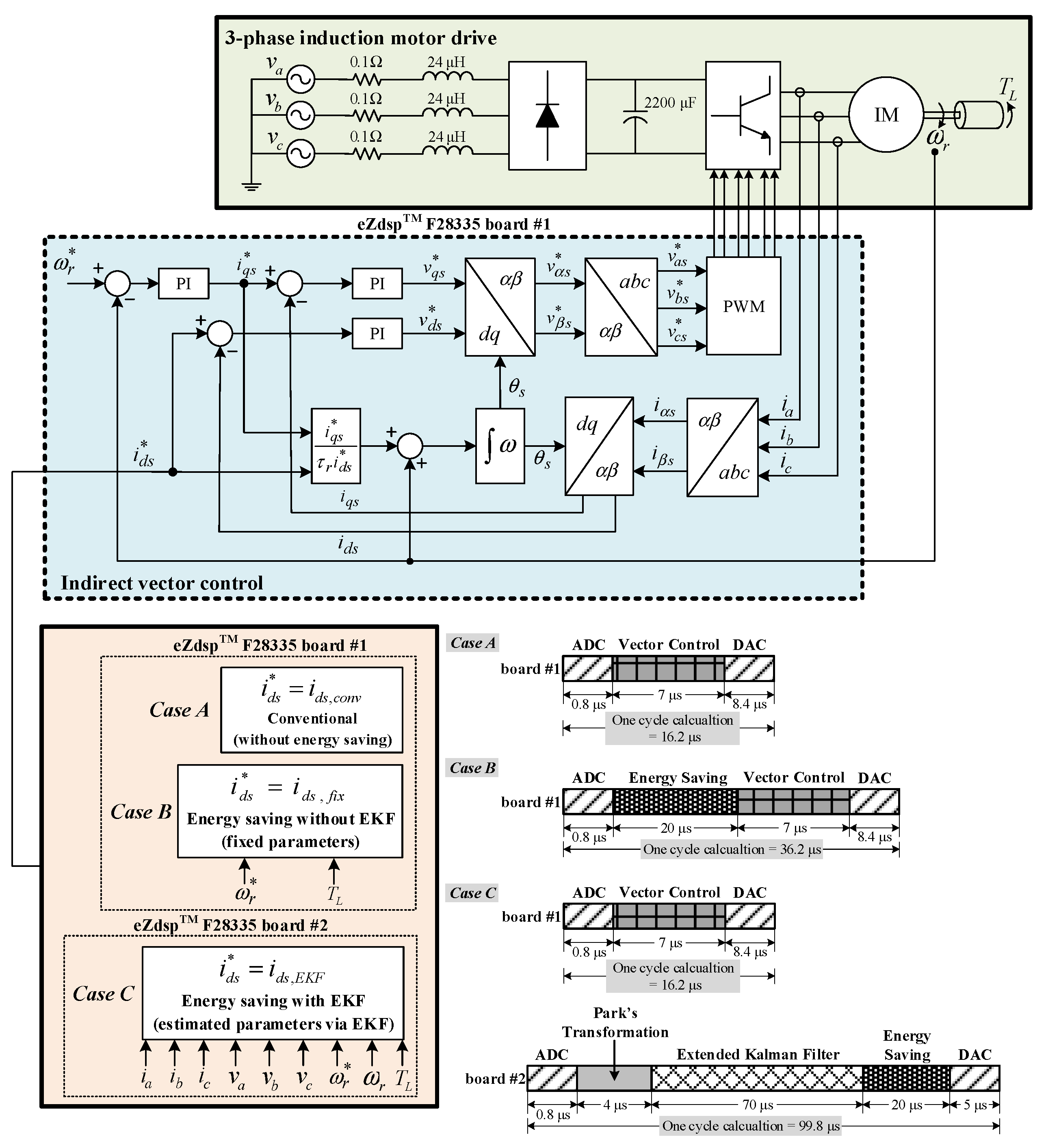
There are three cases for the IM drive presented in this section. The setting of i ds * for the three cases is different. The conventional approach for the IM drive is Case A. The energy-saving approaches for IM drives with and without an EKF are Case B and Case C, respectively. The consuming input power from the three approaches is compared in the experimental testing. From Figure 7, there are two eZdspTM F28335 boards for the indirect vector control, parameter estimation, and energy saving calculation. In Case A and Case B, only one eZdspTM F28335 board #1 is used to implement the indirect vector control and calculate the energy saving, whereas in Case C, the overall calculation and speed control are implemented using two boards. For eZdspTM F28335 board #1, the indirect vector control is implemented on this board. As for eZdspTM F28335 board #2, this board is used to estimate the parameters online and calculate the energy saving. Moreover, Figure 7 shows the computational time on the microcontroller board for all cases. In Case A, the computational time for the indirect vector control is 16.2 µs/cycle. In Case B, the calculation for energy saving is added, and a computational time equal to 20 µs/cycle is used. Thus, the computational time on eZdspTM F28335 board #1 in Case B is equal to 36.2 µs/cycle. For Case C, eZdspTM F28335 board #1 uses 16.2 µs/cycle for indirect vector control calculation, and eZdspTM F28335 board #2 uses 99.8 µs/cycle for online parameter estimation and energy-saving calculation.

4.1. Conventional Approach (Case A)

Figure 7 depicts the speed control topology of the three-phase IM described in this paper. Indirect vector control is applied for a three-phase IM drive in the rotating dq frame. For the d-axis, the PI controller is used for current loop control, and two PI controllers on the q-axis are used for speed loop and current loop control. The flux of the three-phase IM can be controlled by the d-axis, whereas the motor speed and torque can be controlled by the q-axis [47,48]. The PI controller on the q-axis can control the motor speed tracking the speed command ( ω r * ). Additionally, the PI controller on the d-axis can control the i ds following the i ds command ( i ds * ).
As shown in Figure 7, there are three cases (Case A, B and C) for i ds * calculation. In Case A, i ds * is set to the rating value denoted i ds , conv in this paper.

4.2. Energy-Saving Approach without EKF (Case B)

From the power loss equation given in Equation (2), the motor parameters in this equation for this method are fixed to a constant value. In this section, the calculation of the energy-saving process is presented. Equation (2) is used to determine i ds * for the minimum power loss at any operating point.
The minimum value of P loss can be calculated using the partial derivative of P loss with respect to i ds * that is equal to 0. Thus,
d P l o s s d i d s * = d d i d s * [ R d i d s * 2 + R q ( T L K t i d s * ) 2 R d q T L K t ] = 0
or
A i d s * 4 + E = 0
when A =   2 R d and E = 2 R q T L 2 / K t 2 .
Finally, the solution of i ds * for the energy saving can be solved using Equation (30). The i ds * from this section is called i ds , fix . The i ds , fix for energy saving is sent to the indirect vector control of the three-phase IM drive as shown in Figure 7 (Case B).
i d s , f i x = E A 4

4.3. Energy-Saving Approach with EKF (Case C)

In Case C, the calculation of i ds * for energy saving can be achieved using Equation (30) as per the previous section. However, the motor parameters ( R s , R r , L m ) in this case are not fixed to constant values because these parameters change in different operating conditions. Thus, using EKF, R s , R r , and L m are estimated online. The i ds * for energy saving in this case is denoted i ds , EKF .
For the proposed approach, the diagram of the three-phase IM drive system with energy-saving calculation is depicted in Figure 7 (Case C). From Figure 7, the voltages ( v abc ), current ( i abc ) and speed ( ω r ) from the three-phase IM drive system are used for calculation in the EKF algorithm. The estimated values of R s , R r and L m from the EKF are used to determine the i ds , EKF value for energy saving, and this i ds , EKF is sent to the indirect vector control process.
Figure 8 depicts the experimental setup of the three-phase IM drive system for Figure 7. The rating of the three-phase induction motor used in this paper is 0.5 hp. The pendulum machine and its control unit act as the motor’s load. Moreover, the three-phase rectifier is used to convert the AC three-phase source to a DC bus voltage. The three-phase inverter using the IGBT module is the converter that supplies the power to the IM for the drive system. There are two eZdspTM F28335 boards used in the experimental setup.

4.4. Results and Discussion

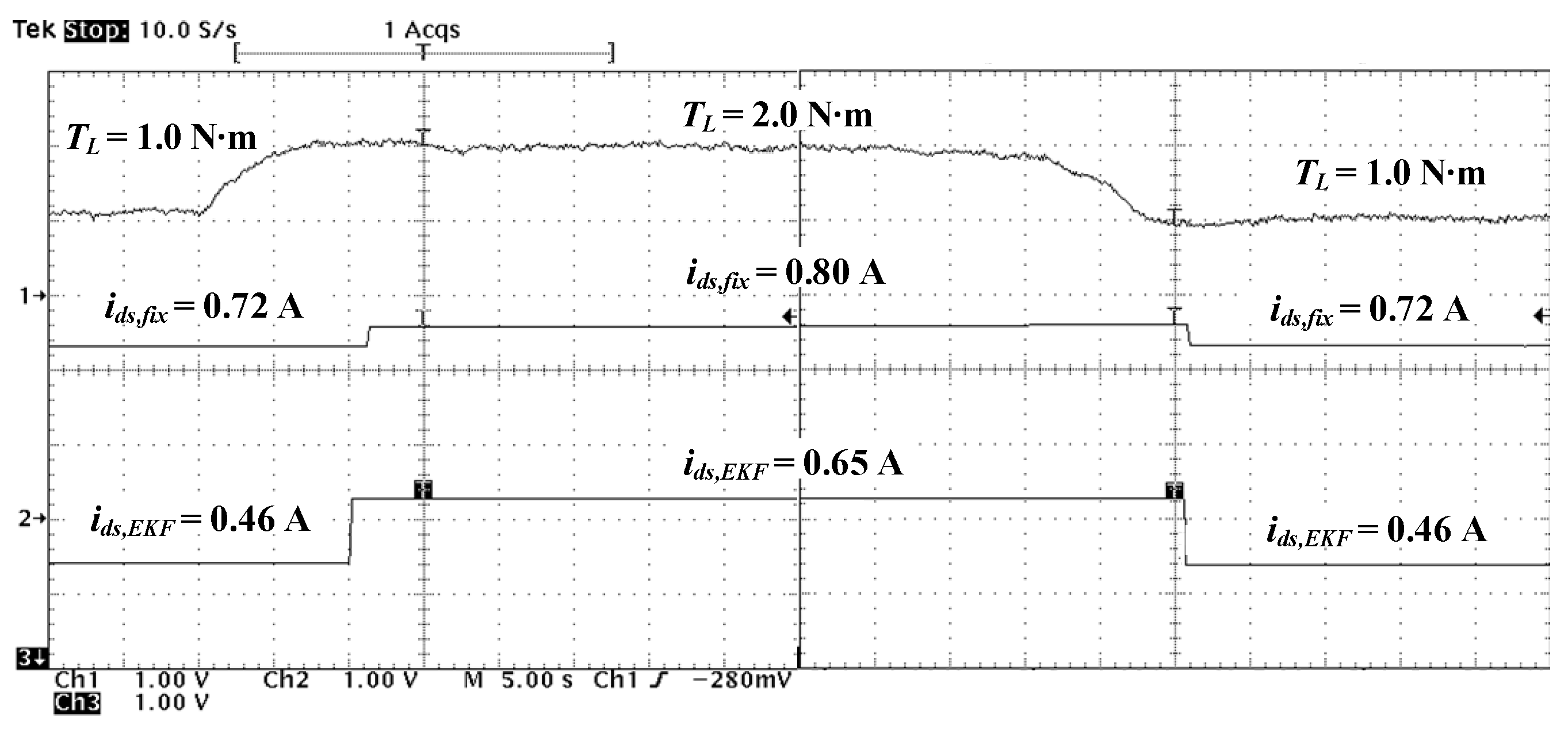
Figure 9 shows the dynamic test of the i ds calculation from the energy-saving approach with and without EKF (Case B and Case C). In this test, the load torque is increased from 1.0 to 2.0 N · m and decreased from 2.0 to 1.0 N · m at a constant speed of 600 rpm. It can be seen from Figure 9 that the i ds , fix and i ds , EKF values can be calculated following the changed conditions. If the operating condition does not change, the last i ds , fix , and i ds , EKF values are sent out. For the other speeds, the calculation of the i ds value is similar to Figure 9.
The conventional approach and the energy-saving approach with and without an EKF described in Section 4.1, Section 4.2 and Section 4.3 are applied to drive the three-phase IM. For the testing, load torque ( T L ) values are in the range 0.5–2.5 N · m . The speeds (N) at any load torque are 300, 600, 900, 1200, and 1390 rpm.
From the experimental testing, the current and voltage values from the three-phase IM drive using the energy saving approach with and without an EKF do not exceed the rating of the motor at any operating point. The experimental results of the IM drive approaches are shown in Table 4.
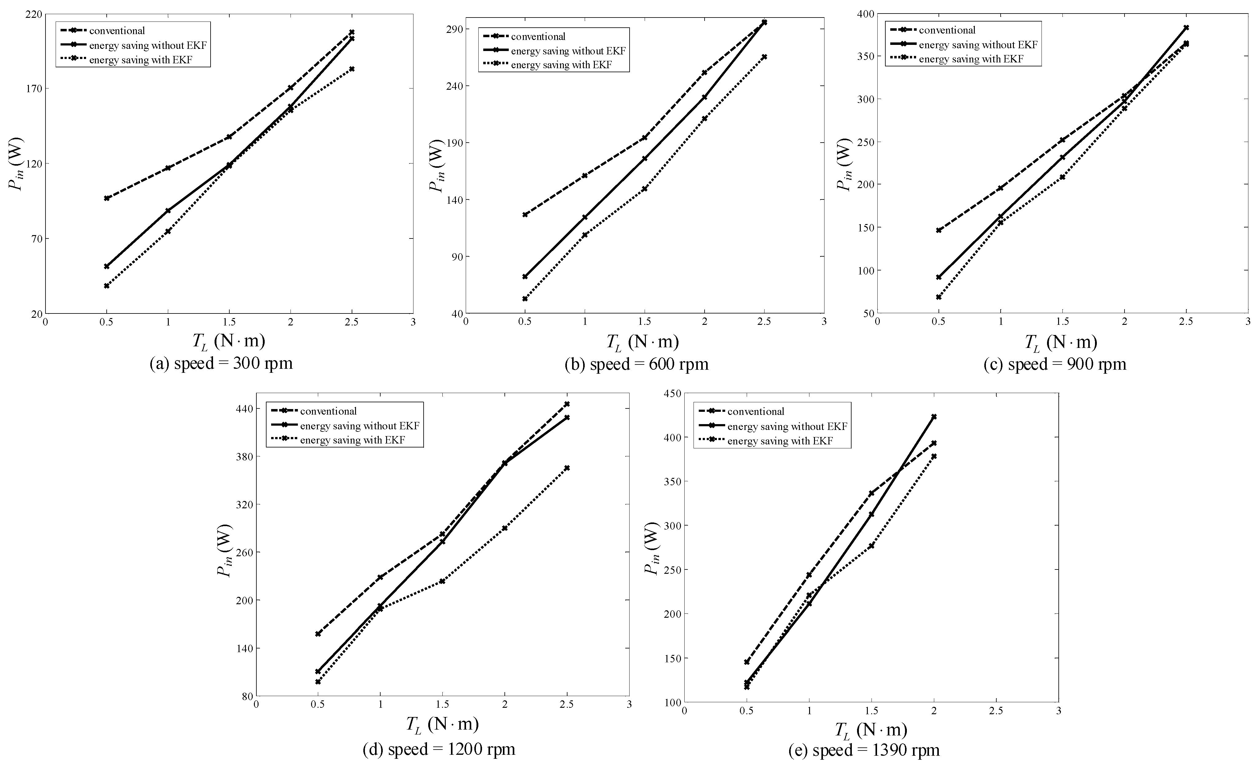
Figure 10 presents the comparison results of the input power ( P in ) consumption from all approaches. The relationship between the input power and the power loss of the motor ( P loss ) can be explained by Equation (31). From this equation, when the output power ( P out ) is a constant value, the P loss value depends on P in . Moreover, the energy consumed (E) by the motor depends on P in , as shown by Equation (32), and t is the running time of the IM. Thus, a decrease in P in indicates that P loss and E decrease, and the energy saving of the motor increases. Additionally, the efficiency ( η ) value can be defined by Equation (33). In the case of decreasing P in , the η value is increased.
P loss = P in P out
E = P in × t
η = P out P in  
In Figure 10, it is shown that the electrical energy consumption of the motor using the energy-saving approach with an EKF is minimal under any operating conditions compared with using the conventional approach and the energy-saving approach without an EKF. In particular, at a slight load torque ( T L = 0.5 N · m , N = 300 rpm), the proposed method can save energy up to 60.18%. The maximum percentage of the energy saving using the energy-saving approach without an EKF is equal to 46.7% compared with the conventional approach.
However, the energy-saving percentage is decreased when the load torque is increased. The average energy-saving percentages achieved using the energy-saving approach with and without an EKF compared with using the conventional approach are 22.31% and 13.27%, respectively. Thus, the results from the implementation suggest that the three-phase IM drive using the energy-saving approach with an EKF can provide the best results in terms of minimum power losses or maximum energy saving percentages. This is because the appropriate motor parameters estimated by the EKF are used to calculate the stator current on the d-axis for energy saving at any operating load torque and speed in real time.

5. Conclusions

In this paper, the application of an EKF to estimate three-phase IM parameters online for energy saving has been presented. The input powers of the motor between the conventional approach and the energy-saving approach with and without EKF have also been shown. These results indicate that the EKF can be used to estimate the appropriate parameters at any load torque and speed, and these accurate motor parameters can be used in the energy-saving approach with the EKF to calculate the stator current on the d-axis for energy saving. The proposed approach can be applied for other three-phase IM sizes, although the implementation of the proposed approach in this work was tested with a 0.5 hp three-phase IM in the laboratory. However, the power loss parameters for the new IM size have changed. Therefore, the parameter identification process using the ATS is repeated. The hardware implementation of the three-phase IM parameter estimation using EKF for energy saving has also been presented in this paper. The speed control topology, parameter online estimation, and energy-saving calculation were implemented using the eZdspTM F28335 microcontroller board. The experimental results confirm that the EKF can obtain the appropriate motor parameters. The calculation of the optimal stator current on the d-axis value using the parameters from the EKF estimation can provide the minimum power losses at any load torque and speed compared with using the conventional and energy-saving approaches without EKF estimation. The maximum energy-saving percentage is 60.18% at slight load torque, and the percentage of the energy saving decreases at high load torque.

Author Contributions

Conceptualization, K.A. (Kongpol Areerak) and T.A.; methodology, S.U.; software, S.U.; validation, K.A. (Kongpol Areerak), S.U., T.A. and K.A. (Kongpan Areerak); formal analysis, K.A. (Kongpol Areerak) and T.A.; investigation, K.A. (Kongpol Areerak) and K.A. (Kongpan Areerak); resources, T.A. and K.A. (Kongpan Areerak); data curation, S.U.; writing—original draft preparation, K.A. (Kongpol Areerak) and S.U.; writing—review and editing, K.A. (Kongpol Areerak); visualization, S.U.; supervision, K.A. (Kongpol Areerak); project administration, K.A. (Kongpol Areerak); funding acquisition, K.A. (Kongpol Areerak) All authors have read and agreed to the published version of the manuscript.

Funding

This research was funded by Suranaree University of Technology (SUT) grant number IRD7-711-66-12-04.

Data Availability Statement

No new data were created or analyzed in this study. Data sharing is not applicable to this article.

Acknowledgments

This work was supported by Suranaree University of Technology (SUT), Thailand.

Conflicts of Interest

The authors declare no conflict of interest.

References

  1. Chapman, S.J. Electric Machinery Fundamentals, 5th ed.; McGraw-Hill: New York City, NY, USA, 2012. [Google Scholar]
  2. Un-Noor, F.; Padmanaban, S.; Mihet-Popa, L.; Mollah, N.M.; Hossain, E. A Comprehensive Study of Key Electric Vehicle (EV) Components, Technologies, Challenges, Impacts, and Future Direction of Development. Energies 2017, 10, 1217. [Google Scholar] [CrossRef]
  3. Yang, Z.; Shang, F.; Brown, I.P.; Krishnamurthy, M. Comparative study of interior permanent magnet, induction, and switched reluctance motor drives for EV and HEV applications. IEEE Trans. Transp. Electrif. 2015, 1, 245–254. [Google Scholar] [CrossRef]
  4. Kusko, A.; Galler, D. Control means for minimization of losses in AC and DC motor drives. IEEE Trans. Ind. Appl. 1983, IA-19, 561–570. [Google Scholar] [CrossRef]
  5. Famouri, F.; Cathev, J.J. Loss minimization control of an induction motor drives. IEEE Trans. Ind. Appl. 1991, 27, 32–37. [Google Scholar] [CrossRef]
  6. Zarchi, H.A.; Hesar, H.M.; Khoshhava, M.A. Online maximum torque per power losses strategy for indirect rotor flux-oriented control-based induction motor drives. IET Electr. Power Appl. 2019, 13, 267–273. [Google Scholar]
  7. Bruno, A.; Caruso, M.; Tommaso, A.O.D.; Miceli, R.; Nevoloso, C.; Viola, F. Simple and flexible power loss minimizer with low-cost MCU implementation for high-efficiency three-phase induction motor drives. IEEE Trans. Ind. Appl. 2021, 57, 1472–1481. [Google Scholar] [CrossRef]
  8. Hu, D.; Xu, W.; Dian, R.; Liu, Y.; Zhu, J. Dynamic loss minimization control of linear induction machine. In Proceeding of the IEEE Energy Conversion and Exposition (ECCE), Cincinnati, OH, USA, 1–5 October 2017; pp. 3598–3603. [Google Scholar]
  9. Shi, Y.; Sarlioglu, B.; Lorenz, R.D. Real-time loss minimizing control of induction machines for dynamic load profiles under deadbeat-direct torque and flux control. In Proceeding of the IEEE Energy Conversion Congress and Exposition (ECCE), Baltimore, MD, USA, 29 September–3 October 2019; pp. 1641–1648. [Google Scholar]
  10. Li, J.; Xiao, F.; Zhang, S. Simplified loss model control efficiency optimization algorithm for vector control induction motor drives. In Proceedings of the 43rd Annual Conference of the Industrial Electronics Society (IECON), Beijing, China, 29 October–1 November 2017; pp. 5178–5183. [Google Scholar]
  11. Uddin, M.N.; Nam, S.W. New online loss-minimization based control of an induction motor drive. IEEE Trans. Ind. Appl. 2008, 23, 926–933. [Google Scholar] [CrossRef]
  12. Nobile, G.; Scelba, G.; Cacciato, M.; Scarcella, G. Loss minimization control for an integrated multidrive topology devoted to hybrid electric vehicles. IEEE Trans. Ind. Electron. 2019, 66, 8345–8360. [Google Scholar] [CrossRef]
  13. Yu, J.; Pei, W.; Zhang, C. A loss-minimization port-controlled Hamilton scheme of induction motor for electric vehicles. IEEE/ASME Trans. Mechatron. 2015, 20, 2645–2653. [Google Scholar]
  14. Rai, K.; Seksena, S.B.L.; Thakur, A.N. A comparative performance analysis for loss minimization of induction motor drive based on soft computing techniques. Int. J. Appl. Eng. Res. 2018, 13, 210–225. [Google Scholar]
  15. Rezk, H.; Elghany, A.A.; Al-Dhaifallah, M.; Sayed, A.H.M.; Ibrahim, M.N. Numerical estimation and experimental verification of optimal parameter identification based on modern optimization of a three phase induction motor. Mathematics 2019, 7, 1135. [Google Scholar] [CrossRef]
  16. Yin, Z.-G.; Zhao, C.; Zhong, Y.-R.; Liu, J. Research on robust performance of speed-sensorless vector control for the induction motor using an interfacing multiple-model extended Kalman filter. IEEE Trans. Power Electron. 2014, 29, 3011–3019. [Google Scholar] [CrossRef]
  17. Zerdali, E.; Barut, M. The comparison of optimized extended Kalman filters for speed-sensorless control of induction motors. IEEE Trans. Ind. Electron. 2017, 64, 4340–4351. [Google Scholar] [CrossRef]
  18. Cirrincione, M.; Pucci, M.; Cirrincione, G.; Capolino, G.-A. Constrained minimization for parameter estimation of induction motors in saturated and unsaturated conditions. IEEE Trans. Ind. Electron. 2005, 52, 1391–1402. [Google Scholar] [CrossRef]
  19. Tang, J.; Yang, Y.; Blaabjerg, F.; Chen, J.; Diao, L.; Lui, Z. Parameter identification of inverter-fed induction motor: A review. Energies 2018, 11, 2194. [Google Scholar] [CrossRef]
  20. Huynh, D.C.; Dunnigan, M.W.; Finney, S.J. On-line parameter estimation of an induction machine using a recursive least-squares algorithm with multiple time-varying forgetting factors. In Proceedings of the IEEE International Conference on Power and Energy (PECON2010), Kuala Lumpur, Malaysia, 29 November–1 December 2010. [Google Scholar]
  21. Popovic, V.; Oros, D.; Vasic, V. Tuning the rotor time constant parameter of IM using the minimum order recursive linear least square estimator. IET Electr. Power Appl. 2019, 13, 266–276. [Google Scholar] [CrossRef]
  22. Debbabi, F.; Nemmour, A.L.; Khezzar, A.; Chelli, S.E. An approved superiority of real-time induction machine parameter estimation operating in self-excited generating mode versus motoring mode using the linear RMS algorithm: Ideal & application. Int. J. Electr. Power Energy Syst. 2020, 118, 105725. [Google Scholar]
  23. Ozkurt, G.; Zerdali, E. Design and implementation of hybrid adaptive extended Kalman filter for state estimation of induction motor. IEEE Trans. Instrum. Meas. 2022, 71, 1–12. [Google Scholar] [CrossRef]
  24. Yang, S.; Ding, D.; Li, X.; Xie, Z.; Zhang, X.; Chang, L. A Novel Online Parameter Estimation Method for Indirect Field Oriented Induction Motor Drives. IEEE Trans. Energy Convers. 2017, 32, 1562–1573. [Google Scholar] [CrossRef]
  25. Yildiz, R.; Barut, M.; Demir, R. Extended Kalman filter based estimations for improving speed-sensored control performance of induction motors. IET Electr. Power Appl. 2020, 14, 2471–2479. [Google Scholar] [CrossRef]
  26. Demir, R.; Barut, M.; Yildiz, R. Reduced order extended Kalman filter based parameter estimations for speed-sensored induction motor drive. Pamukkale Univ. J. Eng. Sci. 2018, 24, 1464–1471. [Google Scholar] [CrossRef]
  27. Leite, V.; Araujo, R.; Freitas, D. A new online identification methodology for flux and parameters estimation of vector controlled induction motors. In Proceedings of the IEEE International Electric Machines and Driver Conference (IEMDC’03), Madison, WI, USA, 1–4 June 2003. [Google Scholar]
  28. Aksoy, S.; Muhurcu, A.; Kizmaz, H. State and parameter estimation in induction motor using the extended Kalman filtering algorithm. In Proceedings of the Modern Electric Power Systems (MEPS), International Symposium, Wroclaw, Poland, 20–22 September 2010. [Google Scholar]
  29. Horvath, K.; Kuslits, M. Dynamic performance of estimator-based speed sensorless control of induction machines using extended and unscented Kalman filters. Power Electron. Drives 2018, 3, 129–144. [Google Scholar] [CrossRef]
  30. Jirdehi, M.A.; Rezae, A. Parameters estimation of squirrel-cage induction motors using ANN and ANFIS. Alex. Eng. J. 2016, 55, 357–368. [Google Scholar] [CrossRef]
  31. Aminu, M. A parameter estimation algorithm for induction machines using artificial bee colony (ABC) optimization. Niger. J. Technol. 2019, 38, 193–201. [Google Scholar] [CrossRef]
  32. Bhowmick, D.; Manna, M.; Chowdhury, S.K. Estimation of equivalent circuit parameters of transformer and induction motor from load data. IEEE Trans. Ind. Appl. 2018, 54, 2784–2791. [Google Scholar] [CrossRef]
  33. Zaky, M.S.; Khater, M.; Yasin, H.; Shokralla, S.S. Review of different speed estimation schemes for sensorless induction motor drives. J. Electr. Eng. 2008, 8, 102–140. [Google Scholar]
  34. Elbuluk, M.E.; Kankam, M.D. Speed sensorless induction motor drives for electrical actuators: Schemes, trends and tradeoffs. In Proceedings of the IEEE National Aerospace and Electronics Conference, Dayton, OH, USA, 14–17 July 1997. [Google Scholar]
  35. Puangdownreong, D.; Areerak, K.-N.; Sri-kaew, A.; Sujijorn, S.; Totarong, P. System Identification via Adaptive Tabu Search. In Proceedings of the IEEE International Conference on Industrial Technology (ICIT’02), Bankok, Thailand, 11–14 December 2002; pp. 915–920. [Google Scholar]
  36. Onea, A.; Horga, V.; Ratoi, M. Indirect vector control of induction motor. In Proceedings of the 6th WSEAS International Conference on Simulation, Modelling and Optimization (SMO’06), Lisbon, Portugal, 22–24 September 2006; pp. 98–103. [Google Scholar]
  37. Prasad, S. Indirect field-oriented control of induction motor. In Proceedings of the Power Electronics Congress (CIEP) 12th International, San Luis Potosi, Mexico, 22–25 August 2010; pp. 102–105. [Google Scholar]
  38. Udomsuk, S.; Areerak, K.-L.; Areerak, T.; Areerak, K.-N. Power loss identification of three-phase induction motor using adaptive tabu search. In Proceedings of the 5th International Electrical Engineering Congress, Pattaya, Thailand, 8–10 March 2017. [Google Scholar]
  39. Yildiz, R.; Barut, M.; Zerdali, E. A comprehensive comparison of extended and unscented Kalman filters for speed-sensorless control applications of induction motors. IEEE Trans. Ind. Inform. 2020, 16, 6423–6432. [Google Scholar] [CrossRef]
  40. Zerdali, E. Adaptive extended Kalman filter for speed-sensorless control of induction motors. IEEE Trans. Energy Convers. 2019, 34, 798–800. [Google Scholar] [CrossRef]
  41. Kim, D.-W.; Park, C.-S. Application of Kalman filter for estimating a process disturbance in a building space. Sustainability 2017, 9, 1868. [Google Scholar] [CrossRef]
  42. Lewis, F.L. Applied Optimal Control and Estimation: Digital Design and Implementation; Prentice Hall: Upper Saddle River, NJ, USA, 1992. [Google Scholar]
  43. Lewis, P.H.; Yang, C. Basic Control Systems Engineering; Prentice Hall: Upper Saddle River, NJ, USA, 1997. [Google Scholar]
  44. Gajic, Z.; Lelic, M. Modern Control Systems Engineering; Prentice Hall: Upper Saddle River, NJ, USA, 1996. [Google Scholar]
  45. Strang, G.; Borre, K. Linear Algebra, Geodesy, and GPS; Wellesley-Cambridge Press: Wellesley, MA, USA, 1997. [Google Scholar]
  46. Boutayeb, M.; Rafaralahy, H.; Darouach, M. Convergence analysis of the Extended Kalman filter used as an observer for nonlinear deterministic discrete-time systems. IEEE Trans. Autom. Control 1997, 42, 581–856. [Google Scholar] [CrossRef]
  47. Bose, B.K. Modern Power Electronics and AC Drives; Prentice Hall: Upper Saddle River, NJ, USA, 2001. [Google Scholar]
  48. Ong, C.-M. Dynamic Simulation of Electric Machinery Using MATLAB/Simulink; Prentice Hall: Upper Saddle River, NJ, USA, 1998. [Google Scholar]
Figure 1. Power loss model of the IM on the dq-axis.
Energies 17 02115 g001
Figure 2. Power loss parameter identification using the ATS method.
Energies 17 02115 g002
Figure 3. Equivalent circuit per phase of the motor.
Energies 17 02115 g003
Figure 4. Equivalent circuit for the no-load test.
Energies 17 02115 g004
Figure 5. Equivalent circuit for the locked-rotor test.
Energies 17 02115 g005
Figure 6. Calculation of the extended Kalman filter.
Energies 17 02115 g006
Figure 7. Indirect vector control of the three-phase IM drive system.
Energies 17 02115 g007
Figure 8. Hardware for the three-phase IM drive system.
Energies 17 02115 g008
Figure 9. Comparison results of the i ds calculation (Case B and Case C).
Energies 17 02115 g009
Figure 10. Energy saving of the motor using different IM drive approaches.
Energies 17 02115 g010
Table 1. Results of the stator resistance measurement.
PhaseStator Resistance (Ω)
U24.80
V25.10
W25.50
Average Value25.13
Table 2. Results for the locked-rotor test.
Test Point12345678Average
Values
V s ϕ 16.1222.7930.4741.0051.0060.8070.3079.30
I s ϕ 0.230.330.430.570.720.840.981.11
PF 0.650.650.650.640.640.640.640.64
R e q 45.6045.3046.3846.0445.5946.1046.1046.3145.92
X e q 53.2652.6954.2355.2754.7352.6955.3554.1454.41
Table 3. Definitions and dimensions of vectors and matrices in the models.
SymbolDefinitionDimensions
x ( k ) state variable vector n × 1
w ( k ) system noise
z ( k ) measurement vector l × 1
v ( k ) measurement noise
A ( k ) state transition matrix n × n
Q ( k ) covariance matrix of w ( k )
R ( k ) covariance matrix of v ( k ) l × l
u ( k ) deterministic input vector m × 1
B ( k ) input matrix n × m
H ( k ) measurement matrix l × n
Table 4. Experimental results of IM drive approaches.
T L ( N · m )N
(rpm)
Case ACase BCase C
Conventional
Approach
Energy-Saving Approach without EKFEnergy-Saving Approach with EKF
i ds , conv (A) P in , conv (W) i ds , fix
(A)
P in , fix
(W)
i ds , EKF
(A)
P in , EKF (W)
0.53000.9496.580.5951.480.4638.46
600126.180.5772.170.4152.23
900146.550.5491.970.3668.27
1200157.320.50110.730.3197.37
1390145.090.48122.170.26117.14
1.0300117.060.7488.650.5374.44
600160.730.72124.160.46108.57
900195.750.68162.990.43155.03
1200228.010.65192.240.41188.68
1390243.890.62210.670.36220.34
1.5300137.900.80119.000.53118.26
600194.090.77176.000.55149.27
900251.960.73231.460.53208.70
1200282.200.70272.540.53223.44
1390335.890.67312.250.58276.71
2.0300170.550.82158.120.67155.25
600251.200.80229.560.65210.64
900303.790.76296.740.62288.90
1200371.920.72370.920.60289.83
1390392.830.70422.850.82377.72
2.5300207.790.92203.180.86183.07
600295.190.90295.590.84265.09
900364.880.86382.900.74363.99
1200445.740.82429.120.74365.52
Disclaimer/Publisher’s Note: The statements, opinions and data contained in all publications are solely those of the individual author(s) and contributor(s) and not of MDPI and/or the editor(s). MDPI and/or the editor(s) disclaim responsibility for any injury to people or property resulting from any ideas, methods, instructions or products referred to in the content.