Abstract
Investing in green hydrogen systems has become a global objective to achieve the net-zero emission goal. Therefore, it is seen as the primary force behind efforts to restructure the world’s energy, lessen our reliance on gas, attain carbon neutrality, and combat climate change. This paper proposes a power management for a net zero emission PV microgrid-based decentralized green hydrogen system. The hybrid microgrid combines a fuel cell, battery, PV, electrolyzer, and compressed hydrogen storage (CHSU) unit aimed at power sharing between the total components of the islanded DC microgrid and minimizing the equivalent hydrogen consumption (EHC) by the fuel cell and the battery. In order to minimize the EHC and maintain the battery SOC, an optimization-based approach known as the Equivalent Consumption Minimization Strategy (ECMS) is used. A rule-based management is used to manage the power consumed by the electrolyzer and the CHSU by the PV system in case of excess power. The battery is controlled by an inverse droop control to regulate the dc bus voltage and the output power of the PV system is maximized by the fuzzy logic controller-based MPPT. As the hybrid microgrid works in the islanded mode, a two-level hierarchical control is applied in order to generate the voltage and the frequency references. The suggested energy management approach establishes the operating point for each system component in order to enhance the system’s efficiency. It allows the hybrid system to use less hydrogen while managing energy more efficiently.
1. Introduction
Changes in temperature, rising sea levels, variations in the frequency and duration of extreme weather events, and other indicators all point to pollution and greenhouse gas emissions as the main causes of the climate change we are currently experiencing. Due to this, worldwide carbon emissions must be eliminated and drop to zero by 2050 to restrict global warming to 1.5 °C [1]. For this reason, green hydrogen, which is produced exclusively from renewable power, even if it is an energy-intensive process, is more appealing now [2]. Blue and gray hydrogen are extracted from fossil fuels in a pollution-heavy process in many countries. The advantage of green hydrogen is that it can assist in decarbonizing a number of industries that have historically been challenging to clean up [3]. This comprises long-haul transportation as well as the chemical, iron, and steel sectors. As a fuel for vehicles, interest in hydrogen has existed since 1800 and increased in the 1970s due to the oil crisis and again in the 1980s due to technological advancements [4,5]. In 2008, the world was hit hard by the high price of oil. High oil costs have a significant impact on not only the automobile sector but also people’s daily life [6]. The same scenario occurred again in 2023, but this time with the Russian–Ukrainian war. Therefore, nations accelerated their efforts to transition away from oil. In Europe, building energy use makes up 40% of the overall consumption of energy and 36% of the release of greenhouse gases [7]. As the globe moves toward sustainability, and to ensure the zero-carbon energy independence and security act, buildings can be heated and powered by green hydrogen [8]. Microgrids integrating green hydrogen storage can overcome energy challenges and help to achieve the net zero emissions target; that is why this area of research has caught the interest of researchers. The authors of reference [9] proposed an off-grid hybrid renewable energy system compromising PV, WT, and batteries to supply residential buildings, and the excess energy can be used to produce hydrogen via an electrolyzer to be used as a transport fuel for fuel cell cars. In Reference [10], the authors introduced a new concept for energy and water called Power-to-H3. It consists of hydrogen, heat, and rainwater. Hydrogen is produced using green electricity and rainwater is collected from solar panels and used as fuel for fuel cell electric vehicles (FCEVs). A PEM electrolysis supplied by solar PV and a concentrated photovoltaic thermal system in Midelt, Morocco, is investigated in Reference [11]. According to the findings, the optimal amount of hydrogen may be produced by a solar PV installation three times larger in size. RESs, like PV and WT, are characterized by their high dependance on weather conditions; locations that have intense solar radiation as well as rapid wind speeds have the lowest prices for solar and wind energy, respectively. As the authors noted in reference [12], where they studied a WT/concentrated photovoltaic thermal system with hydrogen production in Tangier, Morocco, known for its high wind speed, wind power had a better efficiency in producing hydrogen. According to the authors’ comparative research in reference [13], which was conducted in South Africa and Nigeria, located in the sub-Sahara and characterized by high sun irradiation, using various sun-tracking configurations, PV/FC/electrolyzer/battery/H2 storage is the most effective hybrid renewable energy system. Combining batteries with hydrogen storage in a PV microgrid has the ability to combine the benefits of both technologies. Batteries are utilized for short-term storage and can handle repeated instantaneous power peaks, while hydrogen storage is employed for long-term storage and does not self-discharge [14,15]. To take advantage of the synergy between ESS in this kind of microgrid, energy management strategies are also required. The microgrid EMS’ objectives can be technical, economical, or environmental, depending on the microgrid model and its requirements. The techniques employed for this finality differed from one another in terms of accuracy, complexity, and computation time [16]. In ref. [17], a type of MPC called the receding horizon optimization approach is utilized in PV/WT/hydrogen microgrids to reduce operating costs and decrease the uncertainty associated with solar and wind turbines. An optimal scheduling approach for a PV–hydrogen microgrid is investigated in ref. [18], taking into account the lowest possible energy storage equipment operating costs. In ref. [19], a power management control strategy for an islanded solar microgrid considering the limited life cycle of storage devices is proposed. For a microgrid powered by the power-to-gas system, a two-layer energy management system is suggested in [20]. The supervisory control is based on fuzzy logic and the local control is dedicated to the power converters. A synergistic power control strategy based on max-min game theory is suggested in ref. [21], taking into account hydrogen tank safety and fuel cell life deterioration. In ref. [22], the authors suggested utilizing a two-level hierarchical model-based predictive control with an optimized cost function as an energy management strategy for microgrid construction. The methods used are PI, FLC, MPC, metaheuristic optimization algorithms, stochastic and robust programming, and optimization-based EMS. The PI controller is used to control a single-input, single-output system. On the other hand, FLC and MPC are able to control multi-input and multi-output systems. Nevertheless, FLC requires a significant amount of computation time to compile, particularly in complicated systems. However, MPC requires a precise plant model, which could be challenging if there is a lack of input data. When it comes to metaheuristic optimization methods, the convergence speed to the global optimal solution is extremely slow [16].
Concerning methods used for reducing the hydrogen consumption of hybrid energy storage systems including fuel cells, batteries, and supercapacitors, in ref. [23], the authors present a comprehensive comparison of nine energy management strategies, of which five are the most known. Fuzzy Logic Control, the External Energy Maximization Strategy (EEMS), the State Machine Control Strategy (SMCS), the Proportional—Integral (PI) method, and the Equivalent Consumption Minimization Strategy (ECMS). EEMS requires a comprehensive fuel cell consumption model which is a highly challenging task and the PI method gives good results in energy management but not in reducing hydrogen consumption. The main drawback of SMCS is the requirement of hysteresis control during the state transitions. As a result, this issue affects the EMS’ response when the load requirement varies. The expertise of the author affects the fuzzy logic control’s outcomes. The ECMS, which attempts to reduce the fuel usage in the FC, does not take the power of the supercapacitor into consideration. In a hybrid microgrid, study [24] demonstrated that the ECMS uses the least amount of equivalent hydrogen. A state machine combined with equivalent consumption minimization for fuel cell and supercapacitor for a hybrid tramway was developed and used as an energy management strategy in ref. [25]. A hierarchical state machine energy management system-based minimum utilization cost was used to manage a DC microgrid that integrates photovoltaics, an electrolyzer, a hydrogen tank, a fuel cell, and a battery in [26]. This method reduces the efficiency of the hydrogen energy system by making it generate more electricity in order to keep the battery charged. Most of the publications on the ECMS are based on EVs and tramways in order to minimize the hydrogen consumption in the fuel cell/battery system or in the fuel cell/supercapacitor/battery system, as in references [27,28,29,30,31,32,33,34,35]. For a PV microgrid with a fuel cell and battery, the authors of ref. [24] proposed a two-level management system, with the ECMS algorithm acting as the system layer. This paper does not include the production of hydrogen, and hence, it does not consider the electrolyzer efficiency.
This research examines a hybrid energy storage system consisting of batteries and hydrogen storage in a DC microgrid powered by a photovoltaic array. The main power source and the ESS are connected to a DC bus and interfaced with a single inverter controlled with primary and secondary control under variant load conditions. The hydrogen storage unit consists of a water electrolyzer, compressor, hydrogen tank, and a PEM fuel cell for green hydrogen re-electrification. In order to fulfill the maximum power needs while ensuring the minimization of hydrogen consumption and achieving power sharing between the electrolyzer, the battery, and the fuel cell, the aims of this paper are based on the following points:
- -
- The net-zero-islanded PV microgrid is controlled and managed with a local control layer on the DC side by local power converters. These converters send the power status to the ECMS algorithm-based system control layer.
- -
- A fuzzy logic controller-based MPPT is applied to the PV boost converter in order to maximize the output power of the PV system.
- -
- The compressor and water electrolyzer are controlled according to the level of charge in the hydrogen tank, as well as the generation and consumption of power in the microgrid.
- -
- Fuel cell nonlinearity can cause performance degradation with time, which may increase parasitic losses and membrane degradation and, as a result, decrease the fuel cell system’s lifecycle and efficiency. To solve this problem, a sliding mode control-based exact feedback linearization is used to control the output current of the fuel cell.
- -
- A cost function optimization problem based on an equivalent consumption minimization strategy is designed and used to minimize the consumption of green hydrogen, as can be seen in Figure 1.
- -
- A primary control, a type P/F, and Q/V droop control with a virtual output impedance, and a centralized secondary control are used to generate the referenced voltage and frequency of the islanded microgrid. The studied system is presented in Figure 2.
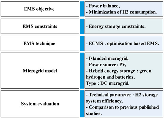
Figure 1.
Design of the optimization-based EMS.
The sections that follow are organized as follows: hybrid energy system modeling and control is displayed in Section 2, and an equivalent consumption minimization strategy is presented in Section 3; the results are presented in Section 4 and discussed in Section 5, and the conclusions are explored in Section 6.
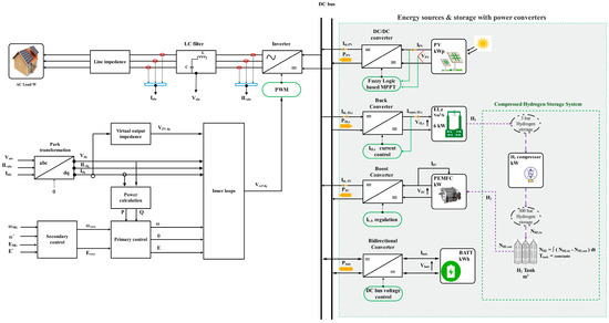
Figure 2.
Configuration of the studied islanded microgrid.
2. Hybrid Energy System Modeling and Control
2.1. Fuzzy Logic Controller-Based MPPT for Renewable Hydrogen Conversion System
Fuzzy Logic Control (FLC)-based MPPT is a soft computing technique used under uniform insolation and varying weather conditions. FLC has the benefit of not requiring an analytical representation of the system [36]. The FLC operation is built up based on three main components: defuzzification, rules inferences, and fuzzification. Its two inputs are the error (Er) and the change in error (CEr) as mentioned in Figure 3. The incremental duty cycle is the output (∆D) of the fuzzy logic controller for MPPT, and it can have either positive or negative values depending on the location of MPP point. This value will be transmitted to the boost converter. The duty cycle value will be determined by:
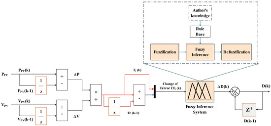
Figure 3.
Fuzzy logic controller.
E(k) represents the location of the MPP, while CE(k) represents the movement of the MPP point, as mentioned in the following equation:
2.2. Water Electrolyzer
Water electrolysis presents a promising and clean pathway for producing pure and green hydrogen; it is a sustainable alternative [37]. In this paper, as mentioned in Equation (5), any extra energy produced by the PV system is, at any given time, sent to the electrolyzer and the compressor when the hydrogen tank does not reach its maximum pressure, where it is used to create hydrogen, which is subsequently sent to the hydrogen storage tank. The Buck Converter’s control mechanism is depicted in Figure 4.

Figure 4.
Current regulation of the PEM electrolyzer buck converter.
The hydrogen produced will not be employed directly by the hydrogen fuel cell. It needs to be kept in a compressed hydrogen storage tank and pressurized to a high pressure. The pressure and hydrogen consumption are directly linked, as demonstrated by the equation for the ideal gas state. The following formula can be used to determine the hydrogen pressure level in the storage tank [21]:
where is the molar mass of hydrogen produced by PEM electrolyzer, and is the molar mass of the hydrogen consumed by the PEM fuel cell. And they can be calculated using the following equations:
The state of hydrogen charge of the hydrogen storage tank is [38]:
where is the current pressure of the hydrogen storage tank, and is the maximum allowable pressure of the hydrogen storage tank.
2.3. PEM Fuel Cell
Because hydrogen is a versatile fuel, an energy carrier, and not an energy source in and of itself, it must be converted into electricity using a device known as a fuel cell stack. Figure 5 represents the PEM fuel cell polarization curve.
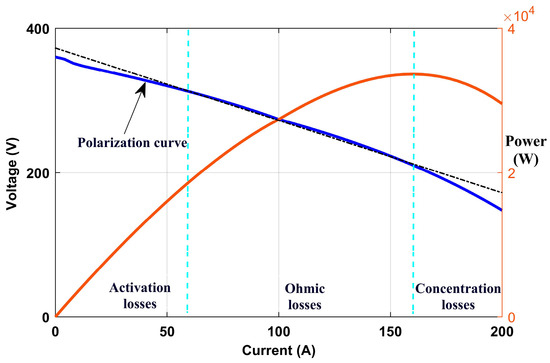
Figure 5.
Polarization curve of the PEM fuel cell stack.
The output voltage drop for small currents is primarily caused by activation losses. Ohmic losses dominate in the typical operating range. And the concentration losses, also called mass transport losses cause the voltage to drop to impractical levels for a large current.
Because the fuel cell and the boost converter are both nonlinear, sliding mode control based on exact feedback linearization is utilized to regulate the boost converter.
- Exact feedback linearization
In general, the state-space model of a nonlinear single-input, single-output system is defined as:
The nonlinear functions are represented by f and g, the control signal is represented by u;, and the output function is represented by y.
The linearized system can be expressed with Li derivatives:
The exact feedback control law of the nonlinear system is:
The inductor and capacitor equations of the boost converter are:
represents the state vector. is the command signal of the fuel cell boost converter.
The new coordinate transformation, which represents the linear system, is represented in the following equation:
The control law is as follows:
where is the new control input of the linear system.
- Sliding mode control
The surface parameter vector S(x) is defined as [39]:
is the output tracking error.
The reaching condition:
The new control law is defined as:
2.4. Battery Control
In order to balance the DC bus power, the battery is regulated by the V-I droop controller [24], as mentioned in Figure 6.
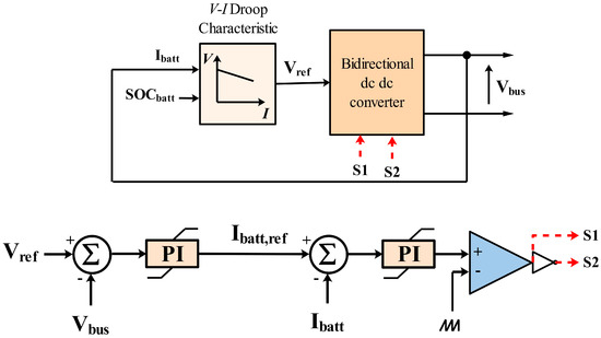
Figure 6.
Battery converter control.
represents the adaptive droop coefficient. It can be calculated as:
is the initial droop coefficient:
∆U is the maximum voltage fluctuation range.
Because of its simplicity and because it is the most similar circuit model [40], the electrical circuit-based model is employed. It consists of an open circuit voltage and an internal resistance. A battery’s output voltage can be written as:
where
Estimating the Internal Resistance of Lithium-Ion Batteries
Miscellaneous methods can be employed to determine a battery’s internal resistance, as mentioned in ref. [41], including the Multi-Hybrid Pulse Power Characteristic known as M-HPPC, an experimental method using a temperature cycle test and the battery’s charge and discharge at different C rates. Another technique is the Multi-Factor Dynamic Internal Resistance Model MF-DIRM, which is based on the M-HPPC. The difference is that, to determine the function relation of the internal resistance regarding T, SOC, and the C-rate, the least sequence technique employs binary polynomial approximation. Polynomial fitting and experimental fitting, both of which are known by the acronym PFAEF, are other approaches. Using this method, internal resistance is expressed as an exponential function with respect to temperature and as a third-order polynomial with regard to SOC, as mentioned in the following equation:
The approach used in this paper is the PFAEF method. The PFAEF fitting coefficients at multiple C-rates (0.75C, 1.75C, and 2.75C) are listed in Table 1.

Table 1.
PFAEF fitting coefficients at various rates [41].
2.5. DC/AC Converter Control
The inverter is controlled by the P/f, Q/V direct droop control to stabilize the voltage and frequency of the disconnected PV microgrid Figure 7 [42].
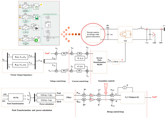
Figure 7.
Primary and secondary control scheme developed in Matlab/Simulink (2018b) [42].
The following equations provide the formulas for frequency and voltage droop:
3. Equivalent Consumption Minimization Strategy
The Equivalent Consumption Minimization Strategy is a management strategy used in a hybrid microgrid to minimize the hydrogen consumption. The goal of the ECMS is to convert electrical energy from an energy storage system to the equivalent fuel consumption. The control calculates the best fuel cell power to employ while minimizing hydrogen consumption [29]. For electrical cars, it is regarded as one of the best control methods [43]. The battery uses DC electrical energy, whereas the FC uses H2 fuel energy. In order to make their energy consumption comparable, the electrical energy consumption of the battery is converted into equivalent fuel consumption. The concept of equivalent fuel consumption is presented in Figure 8 [44].

Figure 8.
ECMS algorithm flow.
The cost function of the optimization problem is expressed as follows:
The constraints applied to the optimization problem are:
According to the literature, experimental data have demonstrated that fuel cell hydrogen consumption can be characterized as a quadratic function for low power and a linear function for high power [45].
where a, b, c, d, e, and are fit coefficients.
The average hydrogen consumption of the fuel cell can be simplified as:
The fuel cell hydrogen consumption can also be calculated using the following equation, as in reference [29]:
The battery-equivalent hydrogen consumption is calculated using average values [24,45,46].
The battery charging and discharging efficiencies can be expressed as follows [47]:
The penalty coefficient k is defined as:
The constant µ serves as a balance coefficient to limit the battery’s SOC value between and . It can be adjusted to accurately match the charge and discharge characteristics of the battery [45]. The fuel cell power is calculated as:
The objective is to calculate the optimized battery power . So and can be considered as constants in the instantaneous problem. Replacing in the previous equation, we can obtain:
Given that:
Considering that:
The optimal solution to the optimization problem, can be expressed as:
The ECMS energy management implementation in Matlab/Simulink is shown in Figure 9 and the PEM fuel cell reference current can be generated using Equation (47).
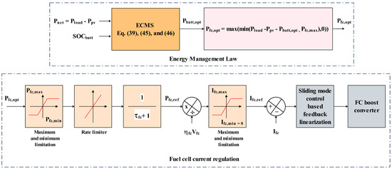
Figure 9.
ECMS energy management strategy.
4. Simulation Results Analysis
This study investigates an islanded PV microgrid under various radiation conditions. It is considered that compressed hydrogen atoms are initially present in hydrogen tank storage. The PV system is controlled under fluctuating radiation by a fuzzy logic controller-based MPPT, as shown in Figure 10.

Figure 10.
PV power system with fuzzy logic controller-based MPPT.
The input current of the PEM electrolyzer reaches its maximum at the peak of the PV power system Figure 11. Since the electrolyzer is powered by the PV system, when there is an excess of energy, the current of the electrolyzer reaches its maximum at the PV system’s peak output power.
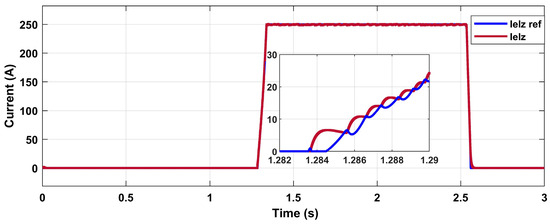
Figure 11.
Current of the PEM electrolyzer.
Figure 12 displays the output power evolution, the input current, and the state of charge of the battery.
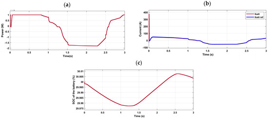
Figure 12.
(a) Output power of battery pack, (b) current of the battery (A), and (c) battery SOC evolution (%).
Figure 13 indicates the PEM fuel cell’s instantaneous hydrogen consumption as well as the output voltage and current of the PEM fuel cell. The fuel cell consumes green hydrogen at almost equilibrium and its consumption starts to drop with the growth in the PV system’s output power.

Figure 13.
(a) hydrogen usage by the PEM fuel cell (g/s); (b) fuel cell output voltage and current.
The amount of hydrogen generated, stored, and used by the green hydrogen system is represented in Figure 14. The amount of hydrogen that is stored is the result of adding the amount already present in the tank storage to the amount created when there is an excess of energy.
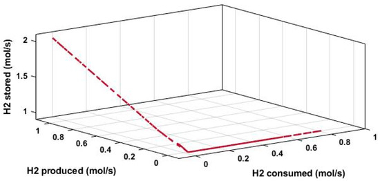
Figure 14.
Quantity of hydrogen produced, stored, and consumed by the system.
Figure 15 illustrates the results of primary and secondary control. The P/f and Q/V droop controls in particular are responsible for changing the frequency and voltage of the microgrid through the primary control. The frequency and voltage deviations are restored by the secondary control, as illustrated in Figure 15a,b. The secondary control is employed to balance the active power in the short term (during transients). The variation in the load affects the voltage and frequency references as well as the output voltage of the DC/AC converter. Furthermore, every fluctuation in the fuel cell affects the dc bus voltage, which in turn impacts the inverter’s output voltage.
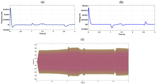
Figure 15.
(a) Voltage reference of the islanded microgrid, (b) reference frequency of the islanded microgrid, and (c) output voltage of the DC/AC converter.
The optimal power of fuel cell generated by the ECMS is presented in Figure 16.
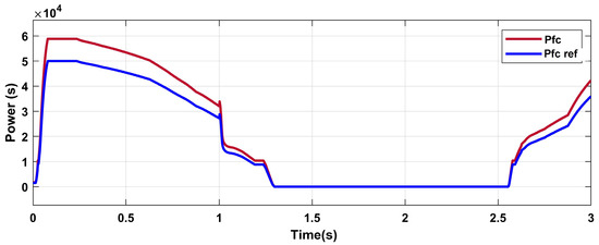
Figure 16.
The optimal output power curve.
As can be observed in Figure 17, the fuel cell’s performance is affected by load variation, high power loads, and the battery when it has to generate or consume power. The fuel cell’s optimal output power is determined by the ECMS, which takes into account the battery’s state of charge and Pnet = Pload − Ppv data processing. When the PV system’s capacity is exceeded by the load demand, the fuel cell supplies the load.
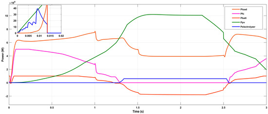
Figure 17.
Energy management results.
When the irradiation reaches its peak value, the PV system operates at its full potential. After the PV system has supplied the required amount of power for the load, any remaining power is used to power the PEM electrolyzer and the compressor. As can be seen between 0 and 0.015 s and between 1.284 s and 2.56 s, the PV supplies the load and the electrolyzer because Pnet < 0.
Between 1.284 s and 2.56 s, the power of the fuel cell decreases because the PV supplies the load and charges the battery to maintain its SOC. And when the output power of the PV decreases, the power of the fuel cell increases, and the battery discharges in order to supply the load.
5. Discussion
The ECMS algorithm determines the optimal output power of the battery pack by computing the equivalent consumption based on the state of the battery (SOC), the load demand, the PV power, and the efficiency of the power source, converters, and ESS, as well as estimating the battery’s internal resistance. This produces the fuel cell’s power reference and, by dividing it by the voltage, the reference current.
As the initial SOC is low (30%) and the load is supplied by the PV, the battery is charged as much as possible between 0 and 0.015 s, as mentioned in Figure 17. Between 0.015 s and 1.284 s, the battery discharged as its SOC was still within the range limits, and the fuel cell minimized its consumption of hydrogen, as mentioned in Figure 13a and Figure 17. And between 1.284 s and 2.56 s, the battery charges as much as possible as its SOC is low. In the case of a low SOC, the maximum instantaneous hydrogen consumption is 5 g/s, compared to that found in ref. [24], which was 6.71 g/s, and the equivalent consumption of hydrogen is 6 g/s, compared to 6.81 g/s found in the same reference. As an outcome, the hydrogen consumption reaches its lowest value when the PV system supplies the load and charges the battery with the help of the fuel cell. This strategy minimizes, on the one hand, the instantaneous hydrogen consumption by the fuel cell, and, on the other hand, it maintains the battery SOC.
The ECMS and flowchart energy management are compared in order to confirm the effectiveness of the suggested energy management strategy. The hydrogen energy storage efficiency system is the technical parameter used to evaluate the system. The findings demonstrate that, in the case of the ECMS algorithm, the hydrogen energy efficiency is increased by 5.26%.
6. Conclusions
In this work, an energy management strategy was proposed in order to enhance the hybrid system’s performance, maintain the battery SOC, and increase the operation efficiency. When the PV system is unable to handle the required load, the PEM fuel cell is globally chosen as the main source. In addition, a battery pack is added to assist the PEMFC stack within its acceptable limits. The fuel cell system can be operated more effectively, hence reducing the FC power dynamics and conserving hydrogen use. This system can be integrated into an islanded net-zero building, considering hydrogen storage limitations, extending the life cycle of the fuel cell stack, and solving the problem of load demand deviation from its desired value.
Within this framework, our forthcoming research endeavors will focus on PV array curtailment power during excessively high generated power and load shedding during excessively low generated power. Moreover, energy management for multi-microgrids-based green hydrogen should be investigated to manage excess energy when the hydrogen storage tank is filled, the battery is fully charged, and load demand is minimal.
Author Contributions
Conceptualization, N.N.; methodology, N.N.; software, N.N.; validation, N.N., S.E.H., M.M. and E.E.; formal analysis, N.N., S.E.H. and A.D.; investigation, N.N. and S.E.H.; resources, S.E.H. and E.E.; data curation, N.N.; writing—original draft preparation, N.N.; writing—review and editing, S.E.H., M.M., E.E. and A.D.; visualization, N.N.; supervision, S.E.H. and E.E.; project administration, S.E.H. and E.E.; funding acquisition, S.E.H. and E.E. All authors have read and agreed to the published version of the manuscript.
Funding
This research received no external funding.
Data Availability Statement
The original contributions presented in the study are included in the article, further inquiries can be directed to the corresponding author.
Conflicts of Interest
The authors declare no conflicts of interest.
Nomenclature
| Battery-equivalent hydrogen consumption, (g/s) | |
| Battery pack capacity, (Ah) | |
| FC hydrogen consumption, (g/s) | |
| FC average consumption | |
| Maximum charging rate | |
| Maximum discharging rate | |
| Rated voltage | |
| ECMS | Equivalent consumption minimization strategy |
| Microgrid voltage | |
| EMS | Energy management system |
| Reverse voltage, (V) | |
| ESS | Energy storage system |
| EV | Electrical vehicle |
| f | Frequency (Hz) |
| Rated frequency | |
| Drooped frequency | |
| Drooped voltage magnitude | |
| Lower heating value of hydrogen | |
| MPC | Model predictive control |
| Power delivered at the rated frequency | |
| FC average power | |
| Power delivered at the rated voltage | |
| Battery rated capacity | |
| R | Universal gas constant 1 atm/(kmol·K) |
| Battery charging resistance, (Ω) | |
| Battery discharging resistance, (Ω) | |
| RESs | Renewable energy sources |
| Internal resistance of the battery, (Ω) | |
| State of charge of the battery | |
| Initial state of charge of the battery | |
| T | Temperature, (Kelvin) |
| Open-circuit voltage of a battery, (V) | |
| WT | Wind turbine |
| Angular frequency of frequency reference | |
| Battery discharging/charging efficiency | |
| Average charging efficiency of the battery | |
| Battery discharging efficiency | |
| Average discharging efficiency of the battery | |
| Efficiency of bidirectional DC/DC converter | |
| Electrolyzer efficiency | |
| Fuel cell efficiency | |
| Efficiency of FC DC/DC converter |
References
- Global Warming of 1.5 °C. Available online: https://www.ipcc.ch/sr15/ (accessed on 29 January 2024).
- The Future of Hydrogen—Analysis, IEA. Available online: https://www.iea.org/reports/the-future-of-hydrogen (accessed on 29 January 2024).
- Yue, M.; Lambert, H.; Pahon, E.; Roche, R.; Jemei, S.; Hissel, D. Hydrogen energy systems: A critical review of technologies, applications, trends and challenges. Renew. Sustain. Energy Rev. 2021, 146, 11118. [Google Scholar] [CrossRef]
- Tang, D.; Tan, G.L.; Li, G.W.; Liang, J.G.; Ahmad, S.M.; Bahadur, A.; Humayun, M.; Ullah, H.; Khan, A.; Bououdina, M. State-of-the-art hydrogen generation techniques and storage methods: A critical review. J. Energy Storage 2023, 64, 107196. [Google Scholar] [CrossRef]
- Niaz, S.; Manzoor, T.; Pandith, A.H. Hydrogen storage: Materials, methods and perspectives. Renew. Sustain. Energy Rev. 2015, 50, 457–469. [Google Scholar] [CrossRef]
- Klell, M. Storage of Hydrogen in the Pure Form. In Handbook of Hydrogen Storage; John Wiley & Sons, Ltd.: Hoboken, NJ, USA, 2010; pp. 1–37. [Google Scholar] [CrossRef]
- Maestre, V.M.; Ortiz, A.; Ortiz, I. The role of hydrogen-based power systems in the energy transition of the residential sector. J. Chem. Technol. Biotechnol. 2022, 97, 561–574. [Google Scholar] [CrossRef]
- Guo, Q.; Chen, Y.; Xu, Y.; Nojavan, S.; Bagherzadeh, H.; Valipour, E. Integration of hydrogen storage system and solar panels in smart buildings. Int. J. Hydrogen Energy 2022, 47, 19237–19251. [Google Scholar] [CrossRef]
- Al-Buraiki, A.S.; Al-Sharafi, A. Hydrogen production via using excess electric energy of an off-grid hybrid solar/wind system based on a novel performance indicator. Energy Convers. Manag. 2022, 254, 115270. [Google Scholar] [CrossRef]
- van der Roest, E.; Snip, L.; Fens, T.; van Wijk, A. Introducing Power-to-H3: Combining Renewable Electricity with Heat, Water and Hydrogen Production and Storage in a Neighbourhood. Appl. Energy 2020, 257, 114024. [Google Scholar] [CrossRef]
- Khouya, A. Hydrogen Production Costs of a Polymer Electrolyte Membrane Electrolysis Powered by a Renewable Hybrid System. Int. J. Hydrogen Energy 2021, 46, 14005–14023. [Google Scholar] [CrossRef]
- Khouya, A. Levelized costs of energy and hydrogen of wind farms and concentrated photovoltaic thermal systems. A case study in Morocco. Int. J. Hydrogen Energy 2020, 45, 31632–31650. [Google Scholar] [CrossRef]
- Babatunde, O.M.; Munda, J.L.; Hamam, Y. Off-grid hybrid photovoltaic—Micro wind turbine renewable energy system with hydrogen and battery storage: Effects of sun tracking technologies. Energy Convers. Manag. 2022, 255, 115335. [Google Scholar] [CrossRef]
- Mah, A.X.Y.; Ho, W.S.; Hassim, M.H.; Hashim, H.; Ling, G.H.T.; Ho, C.S.; Ab Muis, Z. Optimization of a standalone photovoltaic-based microgrid with electrical and hydrogen loads. Energy 2021, 235, 121218. [Google Scholar] [CrossRef]
- Arsalis, A.; Georghiou, G.E.; Papanastasiou, P. Recent Research Progress in Hybrid Photovoltaic–Regenerative Hydrogen Fuel Cell Microgrid Systems. Energies 2022, 15, 3512. [Google Scholar] [CrossRef]
- Van, L.P.; Chi, K.D.; Duc, T.N. Review of hydrogen technologies based microgrid: Energy management systems, challenges and future recommendations. Int. J. Hydrogen Energy 2023, 48, 14127–14148. [Google Scholar] [CrossRef]
- Wang, J.; Li, D.; Lv, X.; Meng, X.; Zhang, J.; Ma, T.; Pei, W.; Xiao, H. Two-Stage Energy Management Strategies of Sustainable Wind-PV-Hydrogen-Storage Microgrid Based on Receding Horizon Optimization. Energies 2022, 15, 2861. [Google Scholar] [CrossRef]
- Zhao, H.; Xu, J.; Xu, K.; Sun, J.; Wang, Y. Optimal Allocation Method of Source and Storage Capacity of PV-Hydrogen Zero Carbon Emission Microgrid Considering the Usage Cost of Energy Storage Equipment. Energies 2022, 15, 4916. [Google Scholar] [CrossRef]
- Dash, V.; Bajpai, P. Power management control strategy for a stand-alone solar photovoltaic-fuel cell–battery hybrid system. Sustain. Energy Technol. Assess 2015, 9, 68–80. [Google Scholar] [CrossRef]
- Kumar, K.; Bae, S. Two-layer energy management strategy for renewable power-to-gas system-based microgrids. J. Energy Storage 2023, 61, 106723. [Google Scholar] [CrossRef]
- Li, J.; Zou, W.; Yang, Q.; Bao, H. Towards net-zero smart system: An power synergy management approach of hydrogen and battery hybrid system with hydrogen safety consideration. Energy Convers. Manag. 2022, 263, 115717. [Google Scholar] [CrossRef]
- Yamashita, D.Y.; Vechiu, I.; Gaubert, J.-P. Two-level hierarchical model predictive control with an optimised cost function for energy management in building microgrids. Appl. Energy 2021, 285, 116420. [Google Scholar] [CrossRef]
- Rezk, H.; Nassef, A.M.; Abdelkareem, M.A.; Alami, A.H.; Fathy, A. Comparison among various energy management strategies for reducing hydrogen consumption in a hybrid fuel cell/supercapacitor/battery system. Int. J. Hydrogen Energy 2021, 46, 6110–6126. [Google Scholar] [CrossRef]
- Han, Y.; Chen, W.; Li, Q.; Yang, H.; Zare, F.; Zheng, Y. Two-level energy management strategy for PV-Fuel cell-battery-based DC microgrid. Int. J. Hydrogen Energy 2019, 44, 19395–19404. [Google Scholar] [CrossRef]
- Li, Q.; Su, B.; Pu, Y.; Han, Y.; Wang, T.; Yin, L.; Chen, W. A State Machine Control Based on Equivalent Consumption Minimization for Fuel Cell/Supercapacitor Hybrid Tramway. IEEE Trans. Transp. Electrif. 2019, 5, 552–564. [Google Scholar] [CrossRef]
- Pu, C.; Li, Q.; Chen, W.; Liu, H. Hierarchical Energy Management Control for Islanding DC Microgrid with Electric-Hydrogen Hybrid Storage System. Int. J. Hydrogen Energy 2019, 44, 5153–5161. [Google Scholar] [CrossRef]
- Mounica, V.; Obulesu, Y.P. Hybrid Power Management Strategy with Fuel Cell, Battery, and Supercapacitor for Fuel Economy in Hybrid Electric Vehicle Application. Energies 2022, 15, 4185. [Google Scholar] [CrossRef]
- Hu, J.; Wang, Z.; Du, H.; Zou, L. Hierarchical energy management strategy for fuel cell/ultracapacitor/battery hybrid vehicle with life balance control. Energy Convers. Manag. 2022, 272, 116383. [Google Scholar] [CrossRef]
- Zhang, W.; Li, J.; Xu, L.; Ouyang, M. Optimization for a fuel cell/battery/capacity tram with equivalent consumption minimization strategy. Energy Convers. Manag. 2017, 134, 59–69. [Google Scholar] [CrossRef]
- Li, H.; Ravey, A.; N’Diaye, A.; Djerdir, A. Online adaptive equivalent consumption minimization strategy for fuel cell hybrid electric vehicle considering power sources degradation. Energy Convers. Manag. 2019, 192, 133–149. [Google Scholar] [CrossRef]
- García, P.; Torreglosa, J.P.; Fernández, L.M.; Jurado, F. Viability study of a FC-battery-SC tramway controlled by equivalent consumption minimization strategy. Int. J. Hydrogen Energy 2012, 37, 9368–9382. [Google Scholar] [CrossRef]
- Li, H.; Ravey, A.; N’Diaye, A.; Djerdir, A. A novel equivalent consumption minimization strategy for hybrid electric vehicle powered by fuel cell, battery and supercapacitor. J. Power Sources 2018, 395, 262–270. [Google Scholar] [CrossRef]
- Lü, X.; Meng, R.; Deng, R.; Long, L.; Wu, Y. Energy economy optimization and comprehensive performance improvement for PEMFC/LIB hybrid system based on hierarchical optimization. Renew. Energy 2022, 193, 1132–1149. [Google Scholar] [CrossRef]
- Lin, X.; Xu, X.; Lin, H. Predictive-ECMS based degradation protective control strategy for a fuel cell hybrid electric vehicle considering uphill condition. eTransportation 2022, 12, 100168. [Google Scholar] [CrossRef]
- Qiang, P.; Wu, P.; Pan, T.; Zang, H. Real-Time Approximate Equivalent Consumption Minimization Strategy Based on the Single-Shaft Parallel Hybrid Powertrain. Energies 2021, 14, 7919. [Google Scholar] [CrossRef]
- Ishaque, K.; Salam, Z. A review of maximum power point tracking techniques of PV system for uniform insolation and partial shading condition. Renew. Sustain. Energy Rev. 2013, 19, 475–488. [Google Scholar] [CrossRef]
- Kumar, S.S.; Himabindu, V. Hydrogen production by PEM water electrolysis—A review. Mater. Sci. Energy Technol. 2019, 2, 442–454. [Google Scholar] [CrossRef]
- Li, Q.; Li, R.; Pu, Y.; Li, S.; Sun, C.; Chen, W. Coordinated control of electric-hydrogen hybrid energy storage for multi-microgrid with fuel cell/electrolyzer/PV/battery. J. Energy Storage 2021, 42, 103110. [Google Scholar] [CrossRef]
- Zhang, F.; Fernández, B.R.; Mosterman, P.J.; Josserand, T. Sliding Mode Control and Feedback Linearization for Non-regular Systems. IFAC Proc. Vol. 2008, 41, 14426–14431. [Google Scholar] [CrossRef]
- Tomasov, M.; Kajanova, M.; Bracinik, P.; Motyka, D. Overview of Battery Models for Sustainable Power and Transport Applications. Transp. Res. Procedia 2019, 40, 548–555. [Google Scholar] [CrossRef]
- Chen, L.; Zhang, M.; Ding, Y.; Wu, S.; Li, Y.; Liang, G.; Li, H.; Pan, H. Estimation the internal resistance of lithium-ion-battery using a multi-factor dynamic internal resistance model with an error compensation strategy. Energy Rep. 2021, 7, 3050–3059. [Google Scholar] [CrossRef]
- Naseri, N.; El Hani, S.; El Harouri, K.; Mediouni, H. Primary and secondary control of an autonomous solar microgrid based power-to-X: Renewable hydrogen conversion. Int. J. Hydrogen Energy 2022, 47, 24421–24438. [Google Scholar] [CrossRef]
- Hwang, H.-Y. Developing Equivalent Consumption Minimization Strategy for Advanced Hybrid System-II Electric Vehicles. Energies 2020, 13, 2033. [Google Scholar] [CrossRef]
- Onori, S.; Serrao, L.; Rizzoni, G. Equivalent Consumption Minimization Strategy. In Hybrid Electric Vehicles: Energy Management Strategies; Springer: London, UK, 2016; Chapter 6. [Google Scholar]
- JTorreglosa, P.; Jurado, F.; García, P.; Fernández, L.M. Hybrid fuel cell and battery tramway control based on an equivalent consumption minimization strategy. Control Eng. Pract. 2011, 19, 1182–1194. [Google Scholar] [CrossRef]
- Han, Y.; Zhang, G.; Li, Q.; You, Z.; Chen, W.; Liu, H. Hierarchical energy management for PV/hydrogen/battery island DC microgrid. Int. J. Hydrogen Energy 2019, 44, 5507–5516. [Google Scholar] [CrossRef]
- Hong, Z.; Li, Q.; Han, Y.; Shang, W.; Zhu, Y.; Chen, W. An energy management strategy based on dynamic power factor for fuel cell/battery hybrid locomotive. Int. J. Hydrogen Energy 2018, 43, 3261–3272. [Google Scholar] [CrossRef]
Disclaimer/Publisher’s Note: The statements, opinions and data contained in all publications are solely those of the individual author(s) and contributor(s) and not of MDPI and/or the editor(s). MDPI and/or the editor(s) disclaim responsibility for any injury to people or property resulting from any ideas, methods, instructions or products referred to in the content. |
© 2024 by the authors. Licensee MDPI, Basel, Switzerland. This article is an open access article distributed under the terms and conditions of the Creative Commons Attribution (CC BY) license (https://creativecommons.org/licenses/by/4.0/).