Abstract
In this paper, a novel dual-three-phase dual-rotor flux-switching permanent magnet (PM) (DRFSPM) machine, building upon conventional FSPM machines, is proposed, where the stator is equipped with dual PMs and dual armature windings, enabling it to operate in various working modes and provide fault tolerance in the event of PM or armature winding faults. Depending on the magnetization directions of the PMs, the proposed DRFSPM machine’s structure can be categorized as 6N-DRFSPM or NS-DRFSPM. In order to assess the electromagnetic performance of the proposed DRFSPM machines with two different magnetizing modes, the topology and operating principle of the two DRFSPM machines are introduced first. Then, the no-load air-gap flux density of the two proposed machines is investigated for a more optimized and purposeful design. Finally, a comparison of the electromagnetic performance between the two proposed DRFSPM machines is conducted by finite-element analysis (FEA), and the FEA-predicted results indicate that the proposed 6N-DRFSPM machine outperforms the NS-DRFSPM machine, as it exhibits a larger back-EMF and average torque and a smaller cogging torque and torque ripple.
1. Introduction
With the rapid development of rare-earth permanent magnet (PM) materials, especially since 1983, the price of high-performance NdFeB PM materials has gradually decreased. Permanent magnet synchronous machines (PMSMs) are widely used in the industrial, agriculture, national defense, and aerospace fields due to their simple structure, high power density, and high efficiency [1,2,3].
According to the placement of PMs, PMSMs can be divided into rotor PMSMs (RPMSMs) and stator PMSMs (SPMSMs). RPMSMs mainly have two types of structures: a surface-mounted structure [4,5] and an interior structure [6]. However, for the surface-mounted PMSM, the PMs are associated with irreversible demagnetization and low output torque due to the direct contact between the PM and the air-gap magnetic field and the use of the protective cover of the PM [7]. For the interior PMSM, the disadvantages include magnetic leakage and difficulty in designing it due to the PMs embedded in the rotor and the complicated magnetic isolation structure [8]. To overcome the above shortcomings of RPMSMs, the SPMSM was proposed, in which the PM and armature winding are placed on the stator, so SPMSMs have gained more and more attention due to their easy heat dissipation and high torque density [9]. Among them, the flux-switching PM machine (FSPM) stands out since it exhibits a simple rotor structure, high reliability, convenient control, and high output power [10,11].
In order to improve the electromagnetic performance and fault tolerance of the motor, several scholars have carried out a lot of research. On the one hand, the internal stator split ratio of the PMSM is often relatively high, and the internal space of the motor cannot be effectively used. In order to solve this problem, the concept of the dual rotor was first introduced into induction machines [12], but there were some shortcomings, such as a low power factor and power density, due to the inherent factors of the motor. Later, some scholars proposed a dual-rotor PMSM [13,14], but the use of brushes or slip rings inevitably has the disadvantage of poor reliability, although the dual-rotor PMSM has a larger torque density. Then, magnetic-geared dual-rotor machines were proposed [15], but the existence of the magnetic blocks made the machine have a larger torque ripple. Therefore, a magnetic-geared dual-rotor motor (MGDRM) was proposed [16], where the inner and outer rotors were divided into three modules with a proper angular offset, and the cogging and torque ripple of the machine were significantly reduced. As a member of MGDRMs, the dual-rotor FSPM machine was first introduced in the axial-field FSPM machine [17,18]. Afterward, because of the low space utilization of the conventional U-core FSPM machine, some scholars proposed a partitioned-rotor FSPM machine, which exhibited a high torque density and high magnet utilization [19]. To overcome the complex structure of the conventional electric vehicle and the shortcomings of low space utilization, a co-axial dual-mechanical-port FSPM (CADMP-FSPM) machine was proposed [20,21], which integrated the generator and the traction motor radially, and the CADMP-FSPM machine improves system integration and makes full use of the space of the vehicle.
On the other hand, to enhance the fault tolerance and reliability of three-phase motors, some scholars proposed multi-phase motors [22,23,24], in which two sets of windings with a proper phase shift were placed on the stator or rotor. Among them, the most popular multi-phase structure is the dual three-phase motor. In [25], a single-rotor dual three-phase FSPM machine was proposed by changing the number of rotor poles and the combination methods of the armature windings of the conventional FSPM machine. Afterward, a series of in-depth research on its fault-tolerant control was conducted on the dual-three-phase single-rotor FSPM machine [26,27,28]. But those are rarely involved in dual-three-phase dual-rotor FSPM (DRFSPM) machines.
In order to make full use of the internal space of the FSPM machine and obtain high fault-tolerant performance, this paper proposes a dual-three-phase dual-rotor FSPM (DRFSPM) machine, which removes the magnetic isolation ring of the conventional dual-rotor FSPM machine and adds a set of PMs and a set of armature windings, so the DRFSPM machine has better fault tolerance and can continue to operate even with one faulty stator winding set or PM set. In addition, the proposed machine has two magnetizing modes, called the 6N-DRFSPM and NS-DRFSPM machines, respectively. DRFSPM machines were briefly introduced in [29], and this paper focuses on their theoretical analysis and performance comparison. The arrangement of this paper is as follows. Firstly, the proposed DRFSPM machines with two different magnetizing modes are introduced, and the topology, winding connection, operating principle, and no-load air-gap flux density of 6N-DRFSPM and NS-DRFSPM machines are investigated. Then, a series of finite-element analysis (FEA) results of the electromagnetic performance, including the back electromotive force (back-EMF), and the torque performance of the two proposed machines are presented. Finally, some conclusions are obtained.
2. Machine Topology
Based on the conventional FSPM machine shown in Figure 1, by removing the lower half of each PM and adding armature slots, as well as embedding the new PM set in the stator yoke above the armature slots, a dual-three-phase dual-rotor FSPM machine can be formed naturally, as shown in Figure 2 and Figure 3. The proposed DRFSPM machines are composed of inner and outer rotors, which have a 5-pole rotor core, and the inner rotor and outer rotor have a mechanical angle difference of 36°. The stator of the machine is embedded in two sets of PMs and two sets of armature windings. Each set of PMs has six pieces, which are evenly distributed along the circumference. Each set of armature windings consists of six coils evenly distributed along the circumference. The two proposed DRFSPM machines have the same structure except for the magnetizing modes.
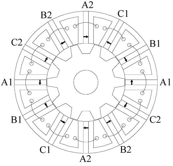
Figure 1.
The structure of the conventional FSPM machine.
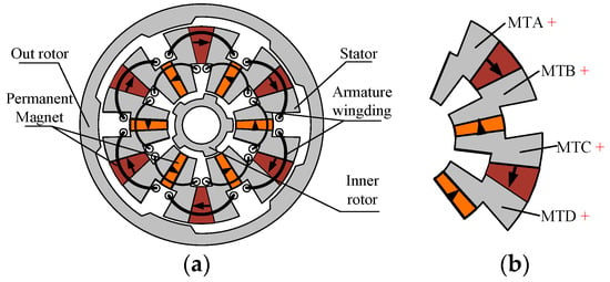
Figure 2.
The structure of the proposed 6N-DRFSPM machine. (a) The 6N-DRFSPM machine. (b) Partial enlargement.
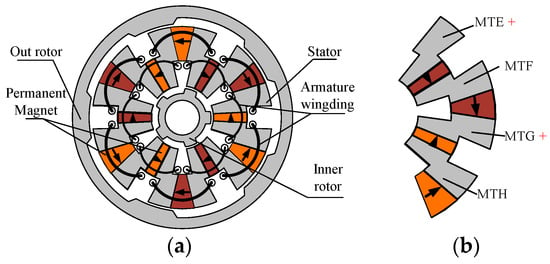
Figure 3.
The structure of the proposed NS-DRFSPM machine. (a) The NS-DRFSPM machine. (b) Partial enlargement.
As shown in Figure 2, the inner and outer PM sets are both circumferentially magnetized, but the magnetizing directions of the two PM sets are opposite; that is to say, two adjacent inner permanent magnets and outer permanent magnets are relatively magnetized, which is called the 6N-DRFSPM machine. In the other one, called the NS-DRFSPM machine, both the inner PM set and outer PM set are magnetized alternately in the circumferential direction, as shown in Figure 3.
For the 6N-DRFSPM machine, the stator is divided into six stator units; each stator unit is embedded in two PMs and two stator modulated teeth (MT), and the stator MT are sandwiched between the inner PM set and the outer PM set. Figure 2b shows an enlarged graphic of part of the stator of the 6N-DRFSPM machine. It should be noted that this enlarged part contains two stator units with four stator MT, namely, MTA, MTB, MTC, and MTD, all of which have a magnetizing effect because the inner PM set and the outer PM set are magnetized toward different directions. However, it is four PMs and four stator MT that form a stator unit for the NS-DRFSPM machine, and it can be seen in Figure 3b that there are four stator MT, MTE, MTF, MTG, and MTH, where MTE and MTG exhibit a magnetizing effect. Therefore, the pole-pair numbers (PPNs) of the proposed 6N-DRFSPM and NS-DRFSPM machines are not the same, with PPN = 6 and PPN = 3, respectively, and the 6N-DRFSPM machine should show superior electromagnetic performance due to more stator MT with a magnetizing effect.
Figure 4 presents the armature winding connections of the proposed DRFSPM machines. It should be noted that the proposed machines exhibit two sets of armature windings, where the two spatial radially distributed coils are serially connected into one phase winding: that is to say, two coils with a 180° phase difference form a phase; i.e., A1 and A2 constitute phase A′ of the inner armature winding, and A1′ and A2′ constitute phase A″ of the outer armature winding.
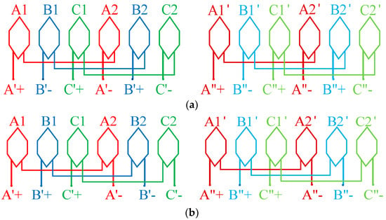
Figure 4.
The armature winding connections of the proposed DRFSPM machines. (a) The 6N-DRFSPM machine. (b) The NS-DRFSPM machine.
Different from the conventional 12-stator-coil/10-rotor-tooth (12/10) FSPM machine, the proposed DRFSPM machines have two sets of armature windings, and only the coil-MF vectors of the two opposite spatial radially distributed coils of each armature winding completely coincide; for example, the A1 and A2 coils form phase A′. As shown in Figure 5, the coil-EMF vectors of the two armature windings differ by 30°, because the outer armature winding and the inner armature winding are spatially misaligned by 30 mechanical degrees. Therefore, a dual-three-phase FSPM machine can be formed, which greatly increases the fault tolerance of the motor.
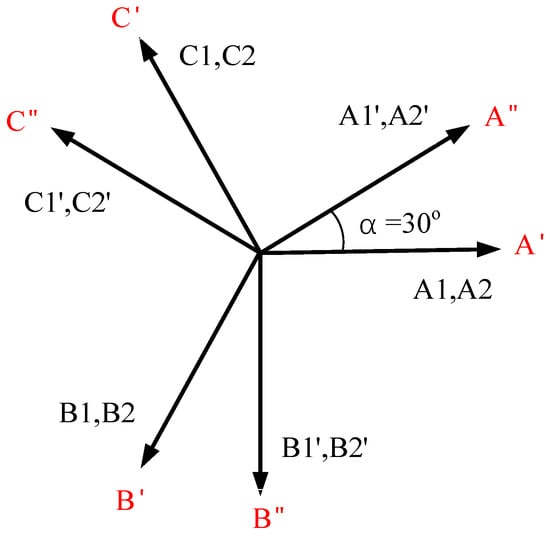
Figure 5.
The coil-EMF vectors of the proposed 6N- and NS-DRFSPM machines.
3. Operating Principle and Key Parameter Design
3.1. Operating Principle
Figure 6 and Figure 7 show the operating principle and effective flux path of the two proposed DRFSPM machines. When the inner and outer salient rotors are in position A and position C, respectively, the two proposed DRFSPM machines have no effective magnetic field lines flowing through phase A′ and phase A″; that is to say, the flux linkage of the proposed machines is zero at this rotor position. When the inner and outer salient rotors are at position B and position D, the effective magnetic field lines passing through the windings of phase A′ and phase A″ for the two proposed machines are the largest. At this time, the flux linkage of phase A′ and phase A″ corresponds to the two positions B and D in Figure 8. In addition, the two proposed machines with different magnetization modes reach the peak value of the flux linkage at the same rotor position.
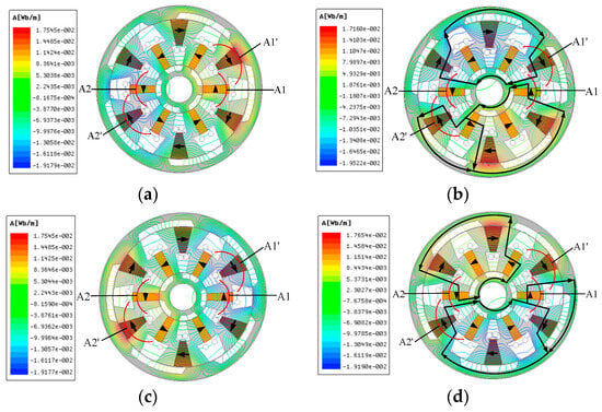
Figure 6.
No-load permanent magnetic field lines of the 6N-DRFSPM machine. (a) Position A. (b) Position B. (c) Position C. (d) Position D.
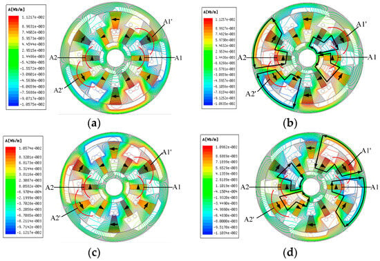
Figure 7.
No-load permanent magnetic field lines of the NS-DRFSPM machine. (a) Position A. (b) Position B. (c) Position C. (d) Position D.
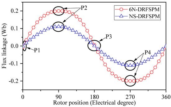
Figure 8.
The no-load flux linkage of the proposed 6N-DRFSPM and NS-DRFSPM machines.
It can be seen in Figure 6 that the magnetic field lines of the 6N-DRFSPM machine are divided into two portions, which form a closed path through the yokes of the inner and outer rotors, and there are four closed paths in total. It should be noted that four coils of phase A′ and phase A″ for the 6N-DRFSPM machine exhibit effective magnetic field lines passing through them. By contrast, the magnetic field lines of the NS-DRFSPM machine only pass through the inner or outer rotor. For the armature windings of phase A′ and phase A″, the closed flux paths flowing through the A1 and A1′ coils are the same, which pass through the inner rotor to form a closed path; meanwhile, the magnetic field lines go through the outer rotor to form a loop, which flows through the A2 and A2′ coils, as shown in Figure 7. It should be noted that there are two coils with no effective magnetic field lines passing through them, i.e., coils A1′ and A2 at position B and coils A1 and A2′ at position D. Therefore, although the closed flux paths of the 6N-DRFSPM machine are longer than those of the NS-DRFSPM machine, the fundamental amplitude of the flux linkage of the 6N-DRFSPM machine should be larger than that of the NS-DRFSPM machine.
Figure 8 shows the no-load flux linkage waveforms of the proposed DRFSPM machines under two different magnetizing modes, and P1, P2, P3, and P4 correspond to the four special positions in Figure 6 and Figure 7, namely, position A, position B, position C, and position D, respectively, where the flux linkages are the sum of the flux linkages of the corresponding inner and outer windings. It can be seen that the fundamental amplitude of the flux linkage of the 6N-DRFSPM machine is larger than that of the NS-DRFSPM machine by about 2 times; this is because the main flux path of the proposed DRFSPM machine is changed due to the different magnetization modes adopted in the proposed DRFSPM machines.
3.2. Design Considerations
For the DRFSPM machines, the magnetomotive force (MMF) produced by PMs includes the inner air-gap MMF and the outer air-gap MMF. Firstly, according to [30,31], by appropriately simplifying the motor model, the inner air-gap MMF modulated by the stator can be obtained as follows:
where is the magnitude of the MMF modulated by the stator, n represents the order of the Fourier series, represents the pole-pair number (PPN) of the stator PM, and is the mechanical position in the stationary coordinate system. Since the open arc of the magnetic teeth on both sides of the stator of the 6N-DRFSPM and NS-DRFSPM machines are exactly identical, the inner air-gap MMF modulated by the stator is exactly the same as the outer air-gap MMF. So, in both the 6N-DRFSPM and NS-DRFSPM machines, satisfies
where is the number of stator units.
However, for the FSPM machines, the pole-pair number is not only related to the number of PMs but also closely related to the direction of magnetization of the PMs. All PMs of the 6N-DRFSPM machine are magnetized in the same direction, while the PMs of the NS-DRFSPM machine are magnetized alternately; hence, the relationship between the stator units of 6N-DRFSPM (NS_6N) and NS-DRFSPM machines (NS_NS) is
In addition, since the inner and outer rotor pole numbers of the two proposed DRFSPM machines are exactly the same, according to [32,33], the inner air-gap MMF modulated by the stator can be obtained as the inner and outer rotor permeance, which can both be expressed as follows:
where represents the amplitude of the rotor Fourier series, and m represents the order of the Fourier series. Therefore, the MMF modulated by the rotors of the two proposed DRFSPM machines can be expressed as follows:
Based on the final air-gap MMF above and , the air-gap PM flux density of two proposed DRFSPM machines can be obtained:
Combining Equations (2), (3), and (6), the harmonic orders of the inner and outer air-gap PM flux densities of the two proposed DRFSPM machines can be acquired, which are listed in Table 1.

Table 1.
Characteristics of 6N-DRFSPM and NS-DRFSPM machines’ air-gap field harmonics.
Figure 9 presents the inner and outer radial air-gap flux densities of the two proposed DRFSPM machines. By carrying out Fourier decomposition on the air-gap flux density above, the radial air-gap flux density harmonic distribution can be acquired, which is exhibited in Figure 10. It can be seen that for the 6N-DRFSPM machine, the dominant PPNs of the inner and outer air-gap field harmonic components are the same, mainly the 1st, 6th, 11th, and 16th. Among them, the 1st, 11th, and 16th pairs of pole harmonics in air-gap PM flux densities are generated due to the modulation of the salient rotor, which satisfies the order of the derived harmonic with m = 1, n = 1, 2, while the 6th harmonic is directly generated by the PMs of the 6N-DRFSPM machine. It can be seen in Figure 10b that for the NS-DRFSPM machine, the main air-gap flux density field harmonics are 2nd, 8th, 4th, 14th, and 10th harmonics, which are modulated by the salient pole rotor, satisfying m = 1, n = 1, 3, 5, and the 3rd, 9th, and 15th harmonics generated by PMs play a dominant role in the NS-DRFSPM machine as well. Although the PPN of the PM of the 6N-DRFSPM is two times that of the NS-DRFSPM machine, both two proposed DRFSPM machines satisfy (m = 0, 1, 2, … n = 1, 2, 3, …).
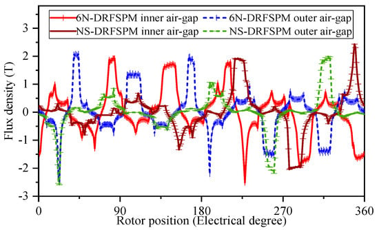
Figure 9.
The radial air-gap PM flux density of 6N- and NS-DRFSPM machines.
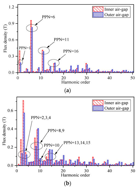
Figure 10.
The open-load radial air-gap PM flux density harmonic orders of the two DRFSPM machines. (a) 6N-DRFSPM machine. (b) NS-DRFSPM machine.
Based on the above no-load PM flux density analysis considerations, the two proposed DRFSPM machines are globally optimized with the goal of maximizing torque as the optimization objective. For a relatively fair comparison, the 6N-DRFSPM and NS-DRFSPM machines share the same key design parameters, including the inner and outer rotors’ outer diameters, the stator’s inner and outer diameters, the air-gap length, the PM volume, the stack length, and the number of turns per phase, which are listed in Table 2.

Table 2.
Key design parameters of the two proposed DRFSPM machines.
4. Discussion of Electromagnetic Performance Analysis
4.1. No-Load Performance
Figure 11 depicts the no-load phase back-EMF waveforms and their corresponding harmonics of the two proposed machines at a rotating speed of 1500 r/min. It can be seen that the amplitude of the peak fundamental phase back-EMF in the 6N-DRFSPM machine is remarkably larger than that in the NS FSPM machine, by about 2 times, which corresponds to the no-load flux linkage in Figure 8. This is because there are more self-loops in the magnetic field of the NS-DRFSPM machine due to different magnetization methods, which results in less effective flux linkage going through the coils of phase A′ and phase A″ than in the 6N-DRFSPM machine. Meanwhile, the total distortion rates (THDs) of the phase back-EMF waveforms of the 6N-DRFSPM and NS-DRFSPM machines are 4.98% and 5.56%, respectively.
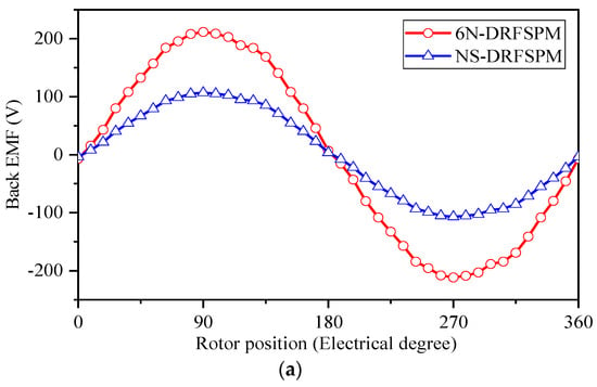
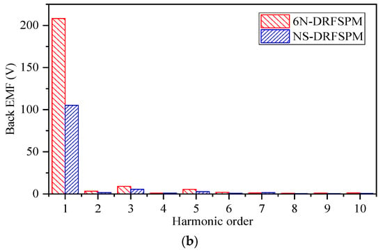
Figure 11.
Waveforms of phase back-EMF per turn at 1500 r/min of two DRFSPM machines with different magnetization modes. (a) Waveforms. (b) Spectra.
Figure 12 presents the cogging torque waveforms and corresponding FFT results of the two proposed DRFSPM machines. As observed in Figure 12a, the peak-to-peak cogging torque value of the 6N-DRFSPM machine is significantly smaller than that of the NS-DRFSPM machine, measuring 0.62 Nm and 1.59 Nm, respectively. Despite the different magnetizing modes used in the two machines, the cogging torque in both cases is primarily generated by the sixth harmonic component, as depicted in Figure 12b.
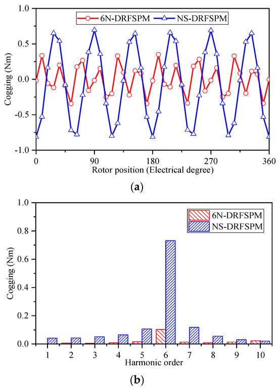
Figure 12.
Cogging torque of two DRFSPM machines with different magnetization modes. (a) Waveforms. (b) Spectra.
4.2. Torque Performance
In addition to evaluating the no-load performance, the torque performance of the two proposed DRFSPM machines under load conditions is also investigated. Figure 13 illustrates the relationship between the electromagnetic torque and the current angle for both DRFSPM machines. It can be observed that the maximum torque for both machines is achieved when the armature current leads the EMF by an angle of 0 degrees, indicating that the id = 0 control strategy can be implemented in both proposed DRFSPM machines.
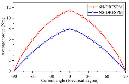
Figure 13.
Curves of torque versus current angle of two proposed DRFSPM machines with different magnetization modes.
As is well known, the electromagnetic torque of a motor can be expressed as follows:
where , , and represent the root-mean-square values of the back-EMF, and , , and are the root-mean-square values of the armature current. From Equation (7), it can be seen that the torque of the motor is proportional to the foundational amplitude of the back-EMF, so the average torque of the 6N-DRFSPM machine is significantly larger than that of the NS-DRFSPM machine due to the larger back-EMF.
Figure 14 shows the average torque waveform of the proposed 6N- and NS-DRFSPM machines when the current density Jsa is 7.5 A/mm2 under id = 0 control. It should be noted that the average torque of the 6N-DRFSPM and NS-DRFSPM machines is 11.71 Nm and 7.92 Nm, respectively, which is consistent with the above analysis. In addition, the 6N-DRFSPM machine has a smaller torque ripple (17.2%) compared to the NS-DRFSPM machine (28.3%). However, both DRFSPM machines have significant torque ripple, mainly due to the large cogging torque. For the DRFSPM machines, torque ripple can be further reduced by selecting stator-slot/rotor-pole combinations such as 12/11 and 12/13 if the electrical frequency allows, by using rotor-skewing, etc.
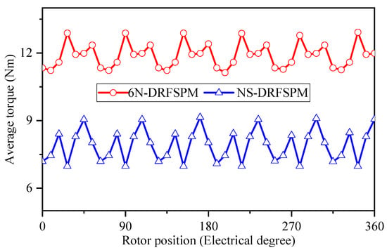
Figure 14.
Average torque of two proposed DRFSPM machines with different magnetization modes.
Figure 15 depicts the average torque waveforms of the two proposed DRFSPM machines at different current densities. It can be seen that the 6N-DRFSPM machine exhibits greater electromagnetic torque compared with the NS-DRFSPM machine when the current density changes from 3 A/mm2 to 9 A/mm2, which further illustrates that the 6N-DRFSPM machine has better torque performance. However, due to the optimization goal of maximizing torque, both the DRFSPM machines have a certain degree of magnetic saturation, resulting in poor anti-saturation ability. Meanwhile, the efficiencies of the 6N-DRFSPM and NS-DRFSPM machines at 1500 r/min are 98.4% and 97.6%, respectively. The specific no-load performance, torque performance, and efficiency of the two proposed DRFSPM machines are listed in Table 3.
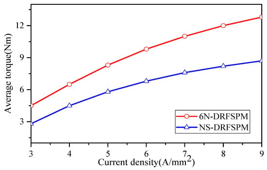
Figure 15.
Average torque versus current density of two proposed DRFSPM machines with different magnetization modes.

Table 3.
Comparative results of the 6N-DRFSPM and NS-DRFSPM machines.
5. Conclusions
In this paper, a new type of dual-three-phase dual-rotor DRFSPM machine with two magnetizing modes, namely, 6N-DRFSPM and NS-DRFSPM machines, is proposed based on conventional FSPM machines.
The no-load PM flux density of the two proposed DRFSPM machines is investigated, revealing that the main components of the 6N-DRFSPM machine are the 1st, 6th, 11th, and 16th harmonics, while the main components of the NS-DRFSPM machine are the 3rd, 4th, 8th, 9th, 10th, 13th, 14th, and 15th harmonics. Both DRFSPM machines satisfy (m = 0, 1, 2, … n = 1, 2, 3, …).
By analyzing and comparing the two proposed DRFSPM machines, several conclusions are drawn. The proposed 6N-DRFSPM machine exhibits superior electromagnetic performance due to more modulated teeth with a magnetizing effect. The effective flux linkages of the NS-DRFSPM machine passing through the coils are lower than those of the 6N-DRFSPM structure, resulting in worse electromagnetic performance since the NS-DRFSPM machine has more self-loops. The electromagnetic performance of the two proposed DRFSPM machines was compared in detail by FEA, and it is concluded that the 6N-DRFSPM machine exhibits better electromagnetic performance, such as a more sinusoidal and larger back-EMF, high average torque, and smaller torque ripple, and higher efficiency.
Author Contributions
Investigation, G.Z. and S.D.; Methodology, Y.C.; Software, Z.L. and Y.Z.; Validation, Z.C. All authors have read and agreed to the published version of the manuscript.
Funding
This research was funded by the 2022 Jiangsu Carbon Peak and Neutrality Technology Innovation Special Fund (Industrial Foresight and Key Core Technology Research) “Research and Development of Key Technologies for Grid Integration Operation and Control of Renewable Energy Sources”, grant number BE2022003.
Data Availability Statement
The original contributions presented in the study are included in the article, further inquiries can be directed to the corresponding author.
Conflicts of Interest
Author Yizhi Chen was employed by the company NARI Technology Co., Ltd. The remaining authors declare that the research was conducted in the absence of any commercial or financial relationships that could be construed as a potential conflict of interest.
References
- Pfaff, G.; Weschta, A.; Wick, A.F. Design and Experimental Results of a Brushless AC Servo Drive. IEEE Trans. Ind. Appl. 1984, IA-20, 814–821. [Google Scholar] [CrossRef]
- Zhu, Z.Q.; Howe, D. Electrical Machines and Drives for Electric, Hybrid, and Fuel Cell Vehicles. Proc. IEEE 2007, 95, 746–765. [Google Scholar] [CrossRef]
- Chau, K.T.; Chan, C.C.; Liu, C. Overview of Permanent-Magnet Brushless Drives for Electric and Hybrid Electric Vehicles. IEEE Trans. Ind. Electron. 2008, 55, 2246–2257. [Google Scholar] [CrossRef]
- El-Refaie, A.M.; Shah, M.R.; Qu, R.; Kern, J.M. Effect of Number of Phases on Losses in Conducting Sleeves of Surface PM Machine Rotors Equipped with Fractional-Slot Concentrated Windings. IEEE Trans. Ind. Appl. 2008, 44, 1522–1532. [Google Scholar] [CrossRef]
- Lu, K.; Li, X.; Zhao, Y.; Yi, P.; Yan, B.; Hua, W. A novel three-vector-based model predictive flux control with low computation complexity for SPMSM. IEEE Trans. Transp. Electrif. 2023. early access. [Google Scholar] [CrossRef]
- Barcaro, M.; Bianchi, N. Interior PM Machines Using Ferrite to Replace Rare-Earth Surface PM Machines. IEEE Trans. Ind. Appl. 2014, 50, 979–985. [Google Scholar] [CrossRef]
- Wu, X.; Wrobel, R.; Mellor, P.H.; Zhang, C.A. Computationally Efficient PM Power Loss Mapping for Brushless AC PM Machines with Surface-Mounted PM Rotor Construction. IEEE Trans. Ind. Electron. 2015, 62, 7391–7401. [Google Scholar] [CrossRef]
- Reddy, P.B.; El-Refaie, A.M.; Huh, K.K.; Tangudu, J.K.; Jahns, T.M. Comparison of Interior and Surface PM Machines Equipped with Fractional-Slot Concentrated Windings for Hybrid Traction Applications. IEEE Trans. Energy Convers. 2012, 27, 593–602. [Google Scholar] [CrossRef]
- Niu, S.; Chau, K.T.; Li, J.; Li, W. Eddy-Current Analysis of Double-Stator Inset-Type Permanent Magnet Brushless Machines. IEEE Trans. Appl. Supercond. 2010, 20, 1097–1101. [Google Scholar]
- Wu, Z.Z.; Zhu, Z.Q. Analysis of Air-Gap Field Modulation and Magnetic Gearing Effects in Switched Flux Permanent Magnet Machines. IEEE Trans. Magn. 2015, 51, 8105012. [Google Scholar] [CrossRef]
- Hua, W.; Cheng, M.; Zhu, Z.Q.; Howe, D. Analysis and Optimization of Back EMF Waveform of a Flux-Switching Permanent Magnet Motor. IEEE Trans. Energy Convers. 2008, 23, 727–733. [Google Scholar] [CrossRef]
- Cui, S.; Cheng, Y.; Chan, C.C. A Basic Study of Electrical Variable Transmission and Its Application in Hybrid Electric Vehicle. In Proceedings of the 2006 IEEE Vehicle Power and Propulsion Conference, Windsor, UK, 6–8 September 2006; pp. 1–4. [Google Scholar]
- Zheng, P.; Liu, R.; Thelin, P.; Nordlund, E.; Sadarangani, C. Research on the Parameters and Performances of a 4QT Prototype Machine Used for HEV. IEEE Trans. Magn. 2007, 43, 443–446. [Google Scholar] [CrossRef]
- Xinhua, G.; Xuhui, W.; Xu, L.; Feng, Z.; Jun, L. Simulation and experiment analysis of dynamic process for an EVT based on dual mechanical port electric machine. In Proceedings of the 2009 IEEE 6th International Power Electronics and Motion Control Conference, Wuhan, China, 17–20 May 2009; pp. 2010–2014. [Google Scholar]
- Chau, K.T.; Zhang, D.; Jiang, J.Z.; Liu, C.; Zhang, Y. Design of a Magnetic-Geared Outer-Rotor Permanent-Magnet Brushless Motor for Electric Vehicles. IEEE Trans. Magn. 2007, 43, 2504–2506. [Google Scholar] [CrossRef]
- Sun, L.; Cheng, M.; Jia, H. Analysis of a Novel Magnetic-Geared Dual-Rotor Motor with Complementary Structure. IEEE Trans. Ind. Electron. 2015, 62, 6737–6747. [Google Scholar] [CrossRef]
- Hao, L.; Lin, M.; Li, W.; Luo, H.; Fu, X.; Jin, P. Novel Dual-Rotor Axial Field Flux-Switching Permanent Magnet Machine. IEEE Trans. Magn. 2012, 48, 4232–4235. [Google Scholar] [CrossRef]
- Zhao, W.; Lipo, T.A.; Kwon, B.I. A Novel Dual-Rotor, Axial Field, Fault-Tolerant Flux-Switching Permanent Magnet Machine with High Torque Performance. IEEE Trans. Magn. 2015, 51, 1–4. [Google Scholar] [CrossRef]
- Xiang, Z.; Quan, L.; Zhu, X. A New Partitioned-Rotor Flux-Switching Permanent Magnet Motor with High Torque Density and Improved Magnet Utilization. IEEE Trans. Appl. Supercond. 2016, 26, 5201905. [Google Scholar] [CrossRef]
- Zhou, L.; Hua, W.; Cheng, M. Analysis and optimization of key dimensions of co-axial dual-mechanical-port flux-switching permanent magnet machines for fuel-based extended range electric vehicles. CES Trans. Electr. Mach. Syst. 2017, 1, 292–299. [Google Scholar] [CrossRef]
- Zhou, L.; Hua, W. Influences of Stator Teeth Number on PM Coupling Levels of Co-Axial Dual-Mechanical-Port Flux-Switching PM Machines. IEEE Trans. Magn. 2019, 55, 8104007. [Google Scholar] [CrossRef]
- Toliyat, H.A.; Lipo, T.A.; White, J.C. Analysis of a concentrated winding induction machine for adjustable speed drive applications. I. Motor analysis. IEEE Trans. Energy Convers. 1991, 6, 679–683. [Google Scholar] [CrossRef]
- Demir, Y.; Aydin, M. A Novel Dual Three-Phase Permanent Magnet Synchronous Motor with Asymmetric Stator Winding. IEEE Trans. Magn. 2016, 52, 8105005. [Google Scholar] [CrossRef]
- Toliyat, H.A.; Xu, L.; Lipo, T.A. A five-phase reluctance motor with high specific torque. IEEE Trans. Ind. Appl. 1992, 28, 659–667. [Google Scholar] [CrossRef]
- Shao, L.; Hua, W.; Cheng, M. Investigation on phase shift between multiple-winding sets in multiphase flux-switching permanent magnet machines. In Proceedings of the 2015 IEEE Energy Conversion Congress and Exposition (ECCE), Montreal, QC, Canada, 20–24 September 2015; pp. 6942–6947. [Google Scholar]
- Hu, M.; Hua, W.; Huang, W.; Meng, J. Digital Current Control of an Asymmetrical Dual Three-Phase Flux-Switching Permanent Magnet Machine. IEEE Trans. Ind. Electron. 2020, 67, 4281–4291. [Google Scholar] [CrossRef]
- Shao, B.; Zhu, Z.Q.; Feng, J.; Guo, S.; Li, Y.; Liao, W. Compensation of Selective Current Harmonics for Switching-Table-Based Direct Torque Control of Dual Three-Phase PMSM Drives. IEEE Trans. Ind. Appl. 2021, 57, 2505–2515. [Google Scholar] [CrossRef]
- Luo, Y.; Liu, C. A Simplified Model Predictive Control for a Dual Three-Phase PMSM With Reduced Harmonic Currents. IEEE Trans. Ind. Electron. 2018, 65, 9079–9089. [Google Scholar] [CrossRef]
- Zhao, G.; Li, Z.; Hua, W.; Ding, S.; Su, P.; Jiang, X. Analysis of a novel dual-three-phase dual-rotor flux-switching permanent magnet machine. In Proceedings of the 2022 IEEE 20th Biennial Conference on Electromagnetic Field Computation (CEFC), Denver, CO, USA, 24–26 October 2022; pp. 1–2. [Google Scholar]
- Li, X.; Wei, Z.; Zhao, Y.; Wang, X.; Hua, W. Design and analysis of surface-mounted permanent-magnet field-modulation machine for achieving high power factor. IEEE Trans. Ind. Electron. 2023. early access. [Google Scholar] [CrossRef]
- Cheng, M.; Han, P.; Hua, W. General Airgap Field Modulation Theory for Electrical Machines. IEEE Trans. Ind. Electron. 2017, 64, 6063–6074. [Google Scholar] [CrossRef]
- Zhu, X.; Cheng, M.; Wang, Y.; Hua, W.; Han, P.; Wang, W. Mathematical Analysis Model of Double-Stator Field Modulation HTS Machine Based on General Airgap Field Modulation Theory. IEEE Trans. Energy Convers. 2022, 37, 475–486. [Google Scholar] [CrossRef]
- Zhao, W.; Hu, Q.; Ji, J.; Ling, Z.; Li, Z. Torque Generation Mechanism of Dual-Permanent-Magnet-Excited Vernier Machine by Air-Gap Field Modulation Theory. IEEE Trans. Ind. Electron. 2023, 70, 9799–9810. [Google Scholar] [CrossRef]
Disclaimer/Publisher’s Note: The statements, opinions and data contained in all publications are solely those of the individual author(s) and contributor(s) and not of MDPI and/or the editor(s). MDPI and/or the editor(s) disclaim responsibility for any injury to people or property resulting from any ideas, methods, instructions or products referred to in the content. |
© 2024 by the authors. Licensee MDPI, Basel, Switzerland. This article is an open access article distributed under the terms and conditions of the Creative Commons Attribution (CC BY) license (https://creativecommons.org/licenses/by/4.0/).