Article

Dead-Time Compensation Using ADALINE for Reduced-Order Observer-Based Sensorless SynRM Drives

1
Goldwind Science & Technology Co., Ltd., Beijing 830063, China
2
School of Electrical Engineering and Automation, Harbin Institute of Technology, Harbin 150001, China
*
Author to whom correspondence should be addressed.
Energies 2024, 17(7), 1693; https://doi.org/10.3390/en17071693
Submission received: 27 February 2024 / Revised: 20 March 2024 / Accepted: 29 March 2024 / Published: 2 April 2024
(This article belongs to the Special Issue Innovation in Motor Drive Systems for Electric Vehicles)

Abstract

:
The inverter dead time effect is non-negligible for the control performance of sensorless synchronous reluctance motor (SynRM) drives at low speeds. In this paper, a reduced-order observer-based sensorless control method for SynRM drives combined with the adaptive linear neurons (ADALINE)-based dead-time compensation is proposed. The reduced-order observer-based sensorless control method is presented, for which is parameter tuning is easy. On this basis, the dead-time compensation strategy using ADALINE filters is proposed to reduce the voltage harmonics effect on the estimation performance of the reduced-order observer. With ADALINE filters, the sixth current harmonic can be successfully filtered out by compensating the voltage directly or fitting the current to compensate the voltage. In this way, the low-speed estimation performance of the reduced-order observer is improved. The effectiveness of the proposed method is verified on a 3 kW SynRM experimental platform.

1. Introduction

Synchronous reluctance motors (SynRMs) have been diffusely applied in home appliances, industrial tools, traction, and other occasions for its low cost, high efficiency, and risk aversion in demagnetization, causing them to be regarded as a valid alternative to permanent magnet machines [1,2,3,4,5]. To the best knowledge of the authors, vector control is the most popular control method in SynRM drives, which depends on accurate and real-time rotor position and speed data for coordinate transformation. Therefore, the acquisition of precise position information is essential to ensure that SynRMs maintain a high-performance control [6], which is usually obtained by position sensors and sensorless methods. Position sensors have shortcomings such as an expensive price, a short life, high installation requirements, and insufficient accuracy, and are easily affected by the working environment. Environmental factors such as humidity, high temperature, vibration, and electromagnetic force can cause the position sensors to not work reliably, which deteriorates the system performance. Hence, sensorless control is considered to be a more effective way to realize high-performance SynRM drives in consideration of a low cost and high reliability [7,8,9]. At high speeds, since the current, voltage, and back-EMF signals of the motor are relatively strong, sensorless control for SynRM drives is usually achieved by the model-based method. At low speeds, due to the poor strength and high measurement difficulty of the signal to noise ratio, the model-based method loses necessity. Sensorless control is usually achieved by the high-frequency signal injection method [10]. However, this method requires the injection of additional signals and produces high frequency noise and electromagnetic interference, which limit its application [11,12]. Therefore, many scholars have studied the model-based method that can be applied to low-speed conditions and put forward some practical and effective methods.
The model-based method takes the back-EMF or flux linkage model of fundamental frequency excitation as its basis to estimate the rotor position information [13,14]. Common sensorless methods based on the model method include the Kalman filter method, sliding mode observer method, model reference adaptive method, reduced-order and full-order observer method, etc. Sensorless methods based on the reduced-order observer method have gained more popularity since the parameter tuning is easy. In low-speed ranges, model-based methods suffer from the low signal to noise ratio caused by modeling uncertainty and inverter nonlinearity [15]. To modify the low-speed performance of the model-based method, many methods for SynRM were proposed and studied. In [16], A. Yousefi-Talouki proposed a sensorless control scheme for SynRM drives on account of the direct-flux vector control (DFVC) method. A hybrid position and speed observer has evolved from the active flux concept and high-frequency signal injection and demodulation, whose functions involves the rotor position estimate over a wide speed range including standstill and flux weakening. In [17], A. Varatharajan proposed a mathematical framework of sensorless position observers, in which a generalized projection vector is employed to calculate the observer error. In addition, the adaptive projection vector is innovatively developed for position error estimation (APP) to solve the problem of unstable power generation. However, the structure of these observers is complex, and a large number of parameters need to be tuned. In [18], T. Tuovinen proposed a back-EMF-based reduced-order position observer with stator-resistance adaptation, which simplifies the observer gain design to the election of two parameters. The robustness at the lowest speed is improved and the tolerable uncertainties in parameter estimates are maximized by introducing the stator-resistance adaptation law. However, the observer has no speed adaptive rate.
In addition to the difficulty of back-EMF estimation caused by the low signal to noise ratio, the dead time effect of the inverter on SynRM drives becomes more and more obvious as the speed decreases [19]. This not only causes harmonics, but also leads to the deterioration of the performance and even failure of the model-based method [20,21]. To optimize the operation performance under low speed and heavy load conditions, a dead-time compensation algorithm is generally added to the driver. The methods mainly include three categories [22]: methods centered on pulse error compensation, methods dependent on model observation, and approaches based on current harmonics monitoring. The methods centered on pulse errors update the symmetric PWM pulses on the basis of the polarity of the phase current to compensate for the voltage output, whose critical issue is its dependence on the current polarity [22]. In [23], a freewheeling-current polarity detection circuit was provided to eliminate the dead time of the PWM control for the inverter, which shows high detection precision. In [24], a controlled switch and an uncontrolled diode are connected in series in two basic switching units, eliminating the dead time of the voltage source inverter and, therefore, eliminating the need for dead time. However, the additional circuitry adds to the cost and reduces the reliability of the system. The methods dependent on model observation build an observer to estimate the voltage error brought out by the dead time effect. In [25], an online estimating scheme for voltage-source inverter nonlinearity and the rotor flux linkage of permanent magnet synchronous machine drives was proposed, and the proposed rotor flux linkage estimation achieved decoupling with the variation of dq-axis inductances. Although good performance can be obtained using observers, these methods require sufficient information about the load parameters to determine a stable observer gain, increasing the complexity of the algorithm [26]. The methods based on the current harmonic detection calculate the compensating voltage value by extracting the sixth harmonic in the current. In [27], a dead-time compensation scheme which takes the fundamental and sixth harmonic components in the synchronous reference frame into account was proposed. However, compared with the steady conditions, the compensation performance degrades within transient conditions such as load and speed changes. In [22], an adaptive-linear-neurons (ADALINEs)-based dead-time compensation method was discussed, whose feedback gains are altered by the means of the least mean square algorithm. Although this method does not require additional hardware circuitry and complex gain tuning, it adds the sixth harmonic to the voltage and deteriorates the operation performance of SynRM drives.
To improve the sensorless control performance under low speed and heavy load conditions, a reduced-order observer-based sensorless control method for SynRM drives combined with the ADALINE-based dead-time compensation is proposed in this article. Firstly, the reduced-order observer-based sensorless control method is studied, the parameters of which are easy to adjust in contrast to the full-order observer. Meanwhile, to reduce the effect of voltage harmonics on the estimation performance of the reduced-order observer, the dead-time compensation strategy using ADALINE-based filters is proposed. The ADALINE filter makes the estimated coefficient close to the harmonic coefficient of the real voltage by neuronal learning. Then, by compensating the voltage directly or fitting the current to compensate for the voltage, the sixth current harmonic aroused by the dead time effect can be, significantly, filtered out. The effectiveness and accuracy of the proposed method is verified on a 3 kW SynRM experimental platform.
The rest of this paper is organized as follows. The reduced-order observer-based sensorless control for SynRM drives is designed in Section 2. The proposed sensorless control strategy combined with ADALINE dead-time compensation is presented in Section 3. Moreover, in Section 4, the feasibility and validity of the proposed method are validated. Finally, Section 5 summarizes the salient findings.

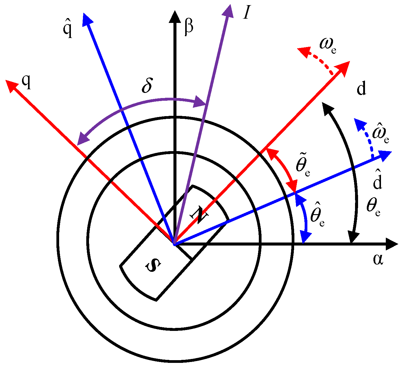
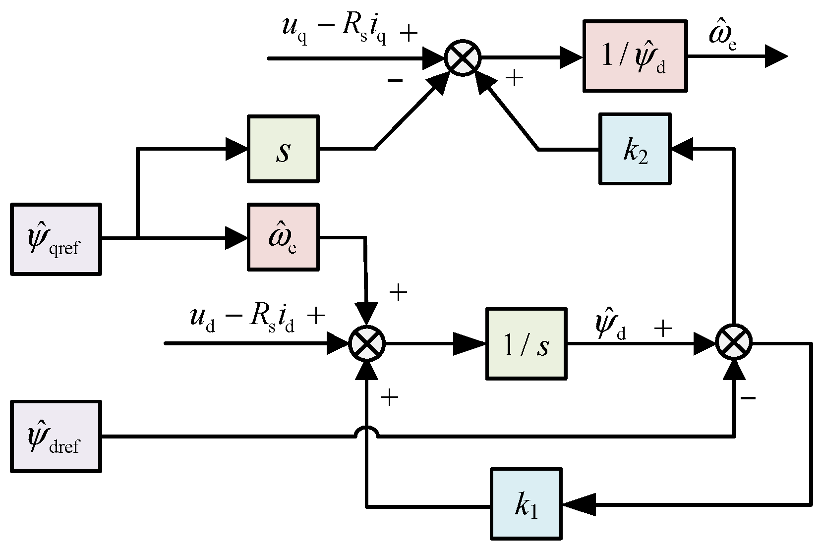
2. Reduced-Order Observer-Based Sensorless Control for SynRM Drives

Real space vectors will be employed throughout this article. The identity matrix and the orthogonal matrix are described as follows:
I = 1 0 0 1 , J = 0 1 1 0
The relationship between the observation and actual coordinate system of an SynRM is shown in Figure 1. The motor is modelled in the dq-axis. θ ^ e is the estimated rotor position. θ e is the actual rotor position. θ ˜ e = θ ^ e θ e is the estimated error.
The actual inductance matrix can be expressed as:
L = e θ ˜ e J L d 0 0 L q e θ ˜ e J
where Ld and Lq are the actual inductances in the dq-axis, respectively.
The estimated inductance matrix can be expressed as:
L ^ = L ^ d 0 0 L ^ q
where L ^ d and L ^ q are the estimated inductances in the dq-axis, respectively.
The voltage equation for SynRM can be expressed as:
d ψ s d t = u s R s ı ˙ s ω ^ e J ψ s
where ψ s represents the stator-flux vector, u s is the stator-voltage vector, and ω ^ e is the estimated rotor angular velocity.
Compared to the full-order observer, which requires both d- and q-axis flux observation errors to correct the output estimated flux value, the reduced-order observer only needs to use the d-axis flux observation error. At the same time, the number of parameters to be tuned is reduced from four to two and the design difficulty is reduced. Although the sensorless methods based on the reduced-order observer and the full-order observer also modify the voltage flux model through the current flux model, the reduced-order observer does not need a speed adaptation rate to estimate the speed and obtains the observed speed directly from the flux model. Therefore, the convergence rate of the reduced-order observer is correspondingly improved compared with that of the full-order observer [28].
In the reduced-order observer, only the d-axis stator flux component is measured, and the estimated flux values are compensated for by the error in the d-axis current-voltage model. The reduced-order observer is expressed in the rotor synchronous coordinate system as:
d ψ ^ s d t = u s R s ı ˙ s ω ^ e J ψ ^ s + K ( ψ ^ s ψ ˙ s ) ,
ψ ˙ s = ψ ^ d ψ ^ q = L ^ d i ^ d L ^ q i ^ q .
K is the observer gain matrix, which can be expressed as:
K = k 1 L ^ d 0 k 2 L ^ d 0 .
A closed-loop reduced-order observer based on the d-axis voltage and current flux model is designed to estimate the rotor position. The expression of the observer is as follows:
d ψ ^ d d t = u d R ^ s i d + ω ^ e L ^ q i q + k 1 ψ ^ d ψ ^ pm L ^ d i d ,
d θ ^ e d t = u q R ^ s i q L ^ q d i q d t + k 2 ( ψ ^ d ψ ^ pm L ^ d i d ) ψ ^ d .
The structure of the reduced-order observer is shown in Figure 2. The designed reduced-order observer is a second-order observer, and only k1 and k2 need to be tuned. The reduced-order observer can obtain the estimated velocity value directly from the flux linkage without the need for the speed adaptive law, and the convergence speed is improved compared with the full-order observer.
The gain of the observer can be expressed as:
k 1 = b ( κ β + 1 ) β 2 + 1 ,
k 2 = b ( κ β 1 ) β 2 + 1
where β = i q / i d , b, and κ are gains whose value can keep the observer stable.

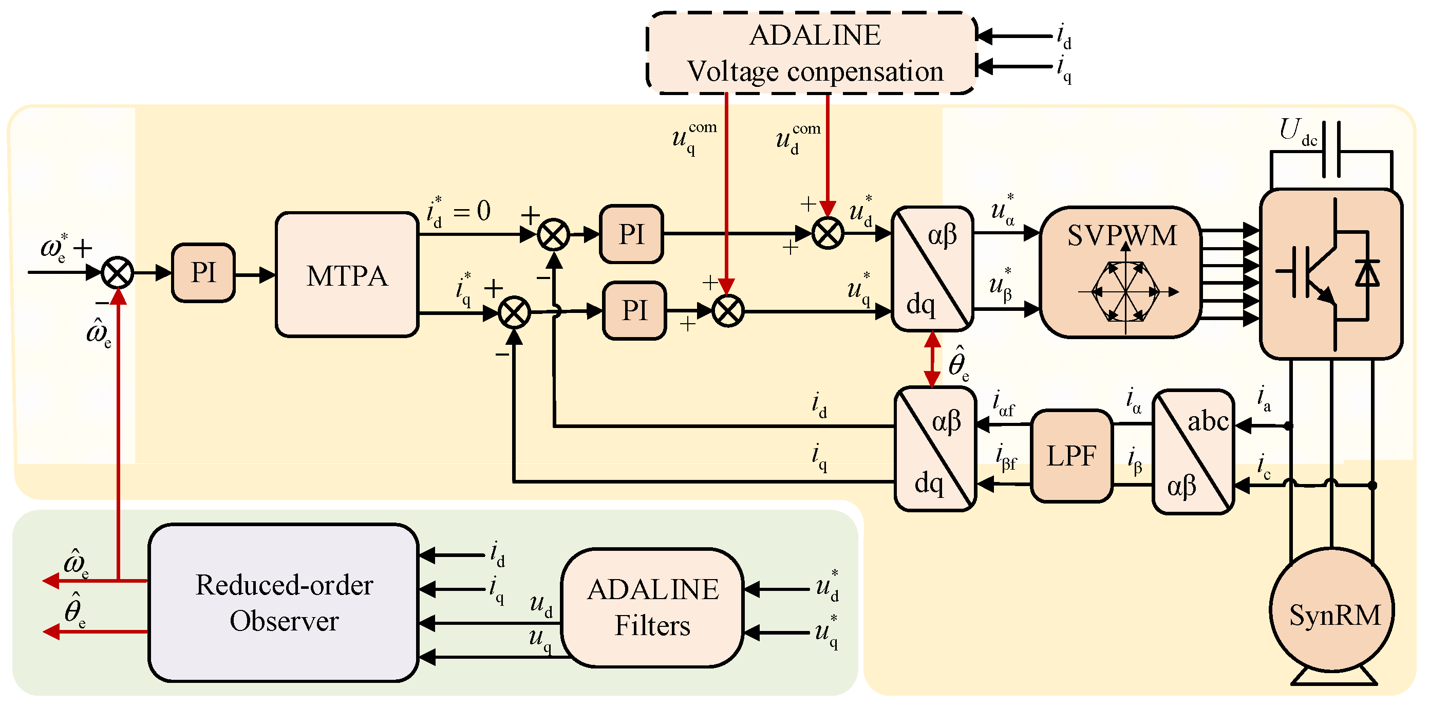
3. Proposed Sensorless Control Strategy Combined with ADALINE Dead Time Compensation

The proposed reduced-order observer-based sensorless control method for SynRM drives combined with the ADALINE-based dead-time compensation is shown in Figure 3. The sixth current harmonic caused by the dead time effect is extracted and compensated for using the ADALINE dead-time compensation algorithm. In this way, the sixth harmonic in the current is effectively reduced. However, a sixth voltage harmonic is generated in the voltage input term, which increases the observer estimation error jitter. Hence, the filters based on ADALINE are used to filter out the voltage harmonics in the observer input signal and enhance the low speed estimation performance of the reduced-order observer.

3.1. Dead Time Effect Analysis

The structure of the PWM inverter is shown in Figure 4. In practice, since the switching device is not an ideal device, it will take some time before the device is fully switched off when a gating signal is received. Therefore, a dead time Td is added between in-phase device switching to prevent damage to the VSI system. However, this results in harmonic components and deteriorates the motor operation, performance especially at low speeds.
The voltage error resulting from the dead time and the tube voltage drop can be expressed in the three-phase coordinate system of the motor. However, since the dead time effect has a serious nonlinear effect on the three-phase voltage of the motor, the voltage cannot be compensated for directly in the three-phase coordinate system. From [22], the voltage error of the motor due to the dead time effect in the dq-axis can be expressed as:
V dd V qd = 4 V d π sin δ n = 6 k [ sin ( n ω e t δ ) n 1 + sin ( n ω e t + δ ) n + 1 ] cos δ n = 6 k [ cos ( n ω e t δ ) n 1 cos ( n ω e t + δ ) n + 1 ]   k N *
where Vdd and Vqd are the voltage errors in the dq-axis, respectively. δ is the angle between the current vector in the rotating coordinate system and the q-axis, as shown in Figure 1.
It can be seen from (12) that, in the rotating coordinate axis system, the dead time effect and inverter non-linearity are mainly to generate the sixth harmonic in the output voltage. The voltage equation of the dq-axis can be expressed as:
u d = i d R s + p i d L d ω e i q L q u q = i q R s + p i q L q + ω e i d L d .
The error of the current in the dq-axis due to inverter non-linearity can be obtained from (13):
i dd i qd = 4 V d π sin δ cos δ 4 V d π n = 6 k [ sin ( n ω e t δ ϕ d n ) ( n 1 ) Z d + sin ( n ω e t + δ ϕ d n ) ( n + 1 ) Z d ] n = 6 k [ cos ( n ω e t δ ϕ q n ) ( n 1 ) Z q cos ( n ω e t + δ ϕ q n ) ( n + 1 ) Z q ]
with Z d = R s 2 + n ω e L d 2 , Z q = R s 2 + n ω e L q 2 .
According to the above analysis, the main negative effect of the dead time effect on the voltage and current of the synchronous reluctance motor is the sixth harmonic of the motor speed, and the harmonic amplitude is only related to the motor speed. Hence, the negative effect of the dead time effect on the SynRM drives is weakened by filtering out the sixth harmonics in the current and voltage.

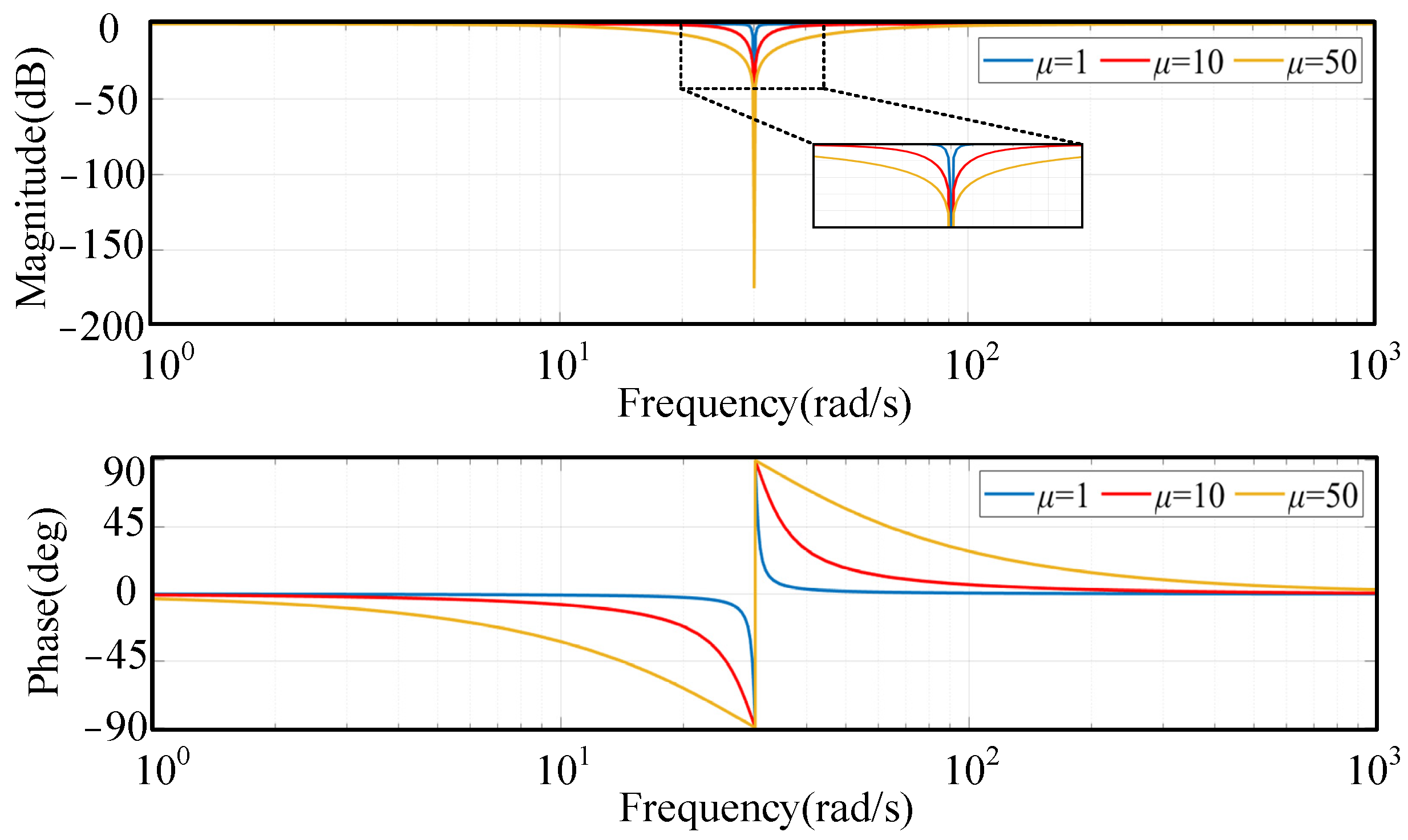
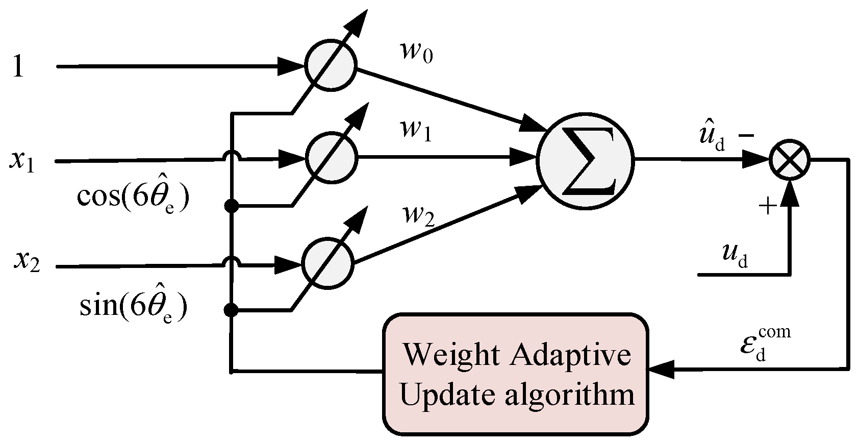
3.2. Voltage Filter Based on the ADALINE Method

In the dead-time compensation algorithm, two filters are required to filter the d-axis and q-axis voltages, respectively. The principle of the dq-axis voltage decomposer based on the ADALINE algorithm is shown in Figure 5. Because the d-axis voltage of the motor mainly contains sixth harmonics, and the components of the other harmonics are small, the d-axis voltage can be simplified to include only DC and sixth harmonic components as follows:
u d ( k ) = a 0 + a 1 cos ( 6 ω e k T s δ ) + b 1 sin ( 6 ω e k T s δ )
where k is the timing of the sampling, Ts is the inverter sampling period, and a0, a1, and b1 are the amplitudes of the DC component of the voltage and the cosine and sine components of the sixth harmonic, respectively.
ADALINE can adjust the filter coefficient by the adaptive algorithm according to the harmonic detection results, so that the characteristics of the filter can change with the changes in harmonics, thus achieving an optimal filtering effect [29]. And the goal of ADALINE filters is to make the estimated coefficients close to the harmonic coefficients of the real voltage through neuronal learning. In the ADALINE voltage decomposer, the estimated voltage is as follows:
u ^ d ( k ) = W d X d T = w 0 + w 1 cos ( 6 ω e k T s δ ) + w 2 sin ( 6 ω e k T s δ )
where X d = 1 cos 6 ω e k T s δ sin 6 ω e k T s δ is the input vector and W d = w 0 w 1 w 2 is the vector of weighting factors for the d-axis voltage.
The root mean square algorithm is used to make Wd update so that it is close to the true coefficient, and the error between the real and estimated values is:
ε d com = u d ( k ) u ^ d ( k ) .
The function J(k) used to minimize the error is usually half the mean square of the error, which can be expressed as:
J ( k ) = 1 2 ( ε d com ) 2 = 1 2 ( u d ( k ) u ^ d ( k ) ) 2 .
The minimum value of J(k) can then be obtained by the gradient descent method, and the gradient of J(k) with respect to the weighting factor is:
J ( k ) = ε d com · ε d com = ε d com X d ( k ) ,
W d ( k ) = W d ( k 1 ) μ ε d com X d ( k )
where μ is the learning rate of the ADALINE algorithm. The q-axis voltage can also be fitted in the same way.
The ADALINE filter based on least mean square algorithm can be equivalent to a second-order band-stop filter with adaptive resonance frequency variation. Compared with FIR, the ADALINE filter does not need a complicated design process, and it can update the internal weight w through the output error to achieve the optimal tracking or elimination of the specified subharmonics. The ADALINE filter only needs to determine the harmonic frequency of the back-EMF ωh and bandwidth μ. The bandwidth is μ and the harmonic frequency of the back-EMF is ωh. The larger the μ, the faster the ADALINE filter converges, but the larger the steady-state error. On the contrary, the smaller the μ, the slower the ADALINE filter converges, but the smaller the steady-state error. In general, μ < 2ωh is taken to cause the ADALINE filter based on the LMS algorithm to be in an underdamped state. The amplitude-frequency response of ADALINE with different values of μ is shown in Figure 6.

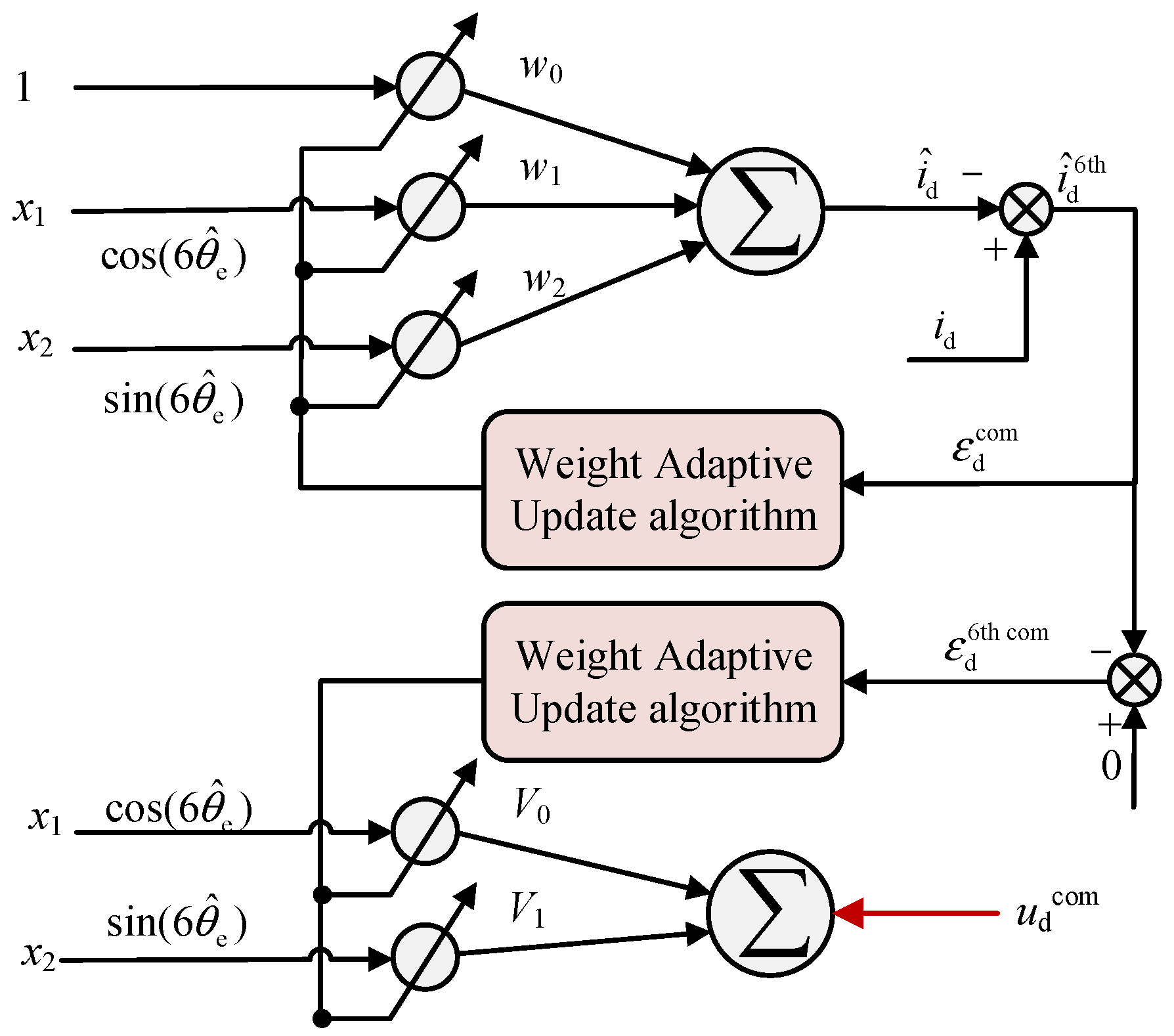
3.3. Voltage Compensation Strategy Based on Current Harmonic Extraction

In voltage-sourced inverters, a separate voltage sensor is usually not designed to measure the output voltage of the inverter, so the harmonics in the output voltage cannot be compensated for by direct fitting. Therefore, it is necessary to eliminate the voltage harmonics by fitting current harmonics, as shown in Figure 7.
The current in the d-axis can also be expressed as:
i ^ d ( k ) = W d X d T = w 0 + w 1 cos ( 6 ω e k T s δ ) + w 2 sin ( 6 ω e k T s δ ) .
Firstly, the current is fitted with an ADALINE and the coefficients of the current are obtained. Then, the amplitude of the sixth harmonic in the current can be derived after the coefficients w1 and w2 are extracted and their values are determined. Further, the amplitude of the sixth harmonic of the current is substituted into another ADALINE filter as shown in Figure 7. Finally, the compensation of the voltage is derived and the coefficients of the voltage compensation can be updated in the same way as:
V ( k ) = V ( k 1 ) η ε Y d ( k ) .
After dead-time compensation, the current does not contain the sixth harmonics, but the sixth harmonic is transferred to the voltage term, so another ADALINE filter needs to be designed in the voltage input part of the reduced-order observer to filter out the sixth harmonics, as shown in Figure 3. In the control system, the reduced-order observer uses the ADALINE filter to filter the voltage harmonics directly. And in the current loop, voltage harmonics are eliminated based on the current information. In this way, the harmonics in the input voltage of the observer are basically filtered out, and the fluctuation of the observed position is reduced.

4. Experimental Results

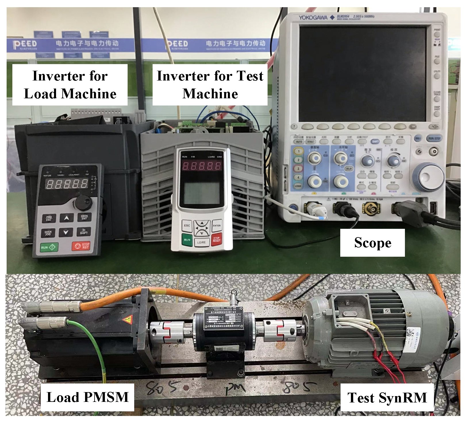
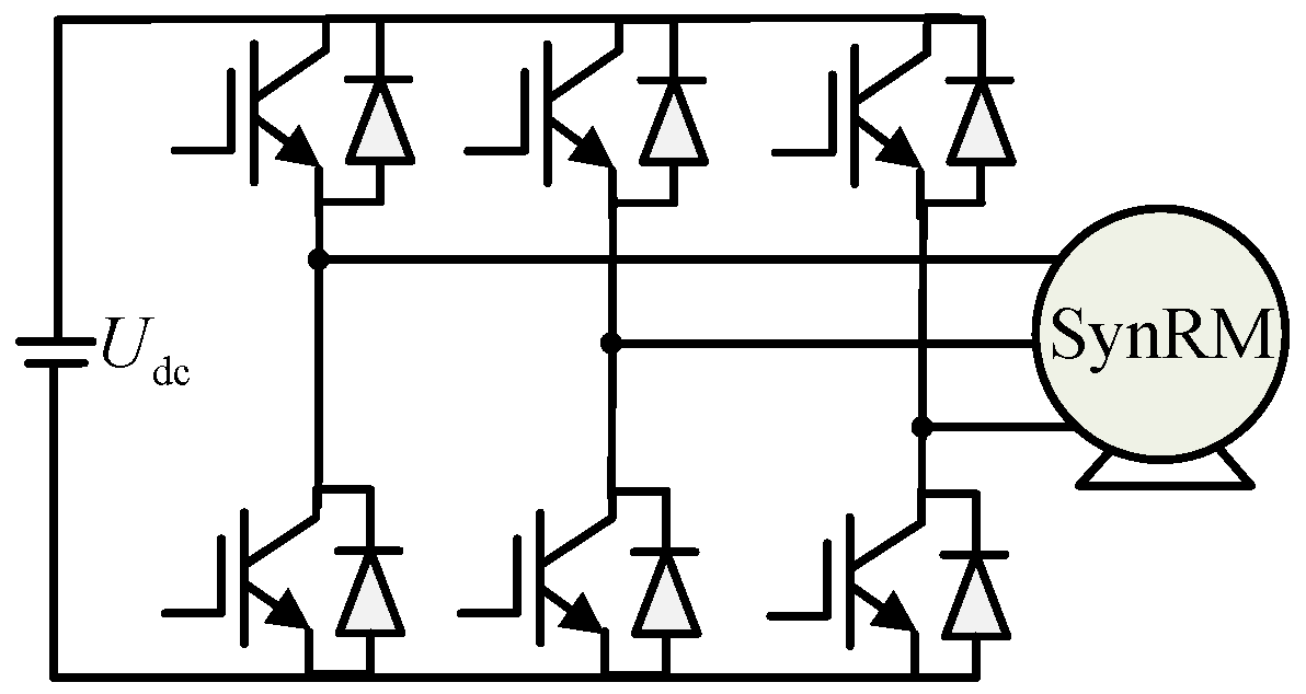
4.1. Experimental Setup

The 3 kW SynRM experimental platform is shown in Figure 8. The test SynRM parameters are shown in Table 1. The load torque for the SynRM is provided by a permanent magnet synchronous motor coaxially coupled to the SynRM. The commercial inverter is produced by STEP Electric Corporation, Shanghai, China. Through the university-industry collaboration pattern, the position sensorless control algorithm can be deployed in the microcontroller. The microcontroller model is STM32F103 ST, Shanghai, China, and the sampling frequency and PWM switching frequency are set at 10 kHz. The absolute encoder with 2048-line is used to detect the actual rotor position and speed and to evaluate the observer’s estimation accuracy. The motor adopts a double closed-loop control system to control the speed. The speed feedback uses the estimated speed of the reduced-order observer, and the inverter output voltage is compensated for using the ADALINE dead-time compensation algorithm.

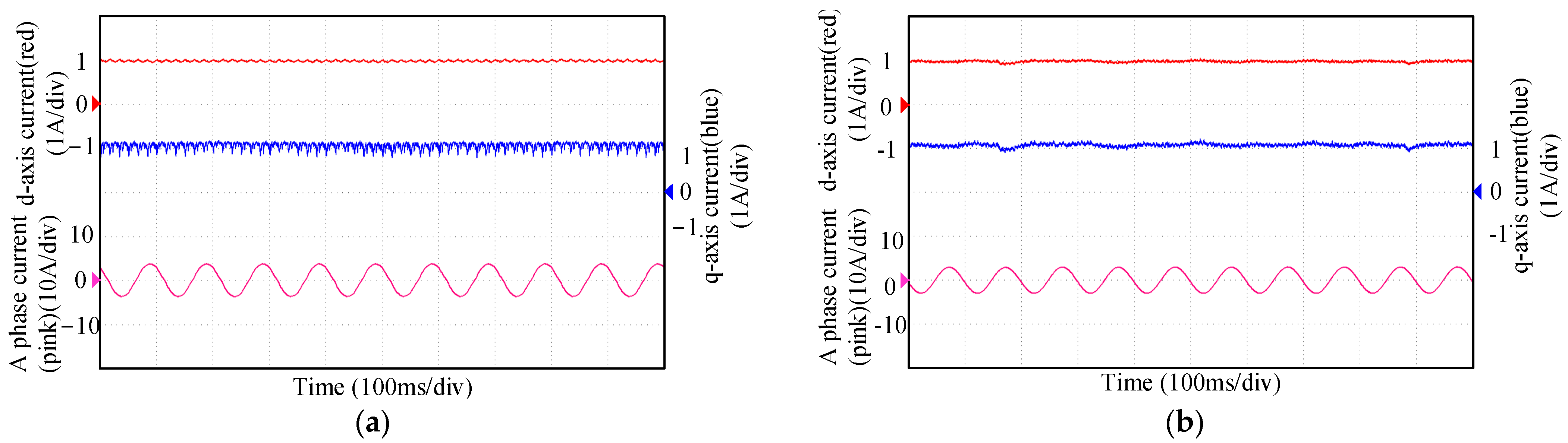
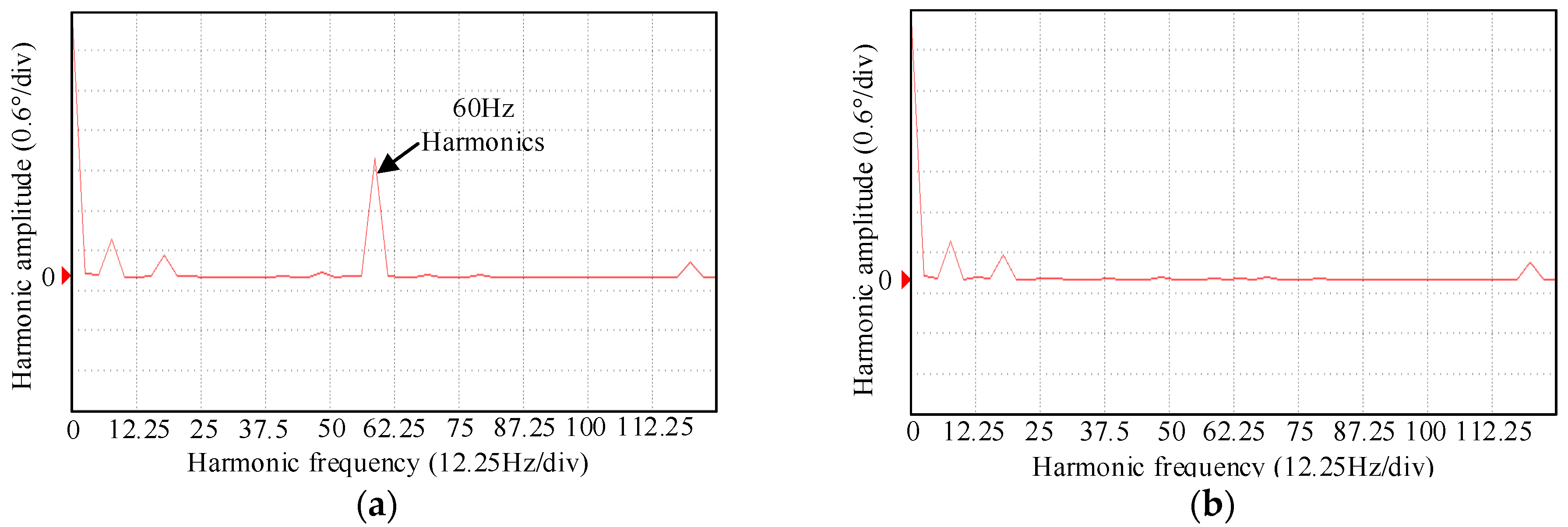
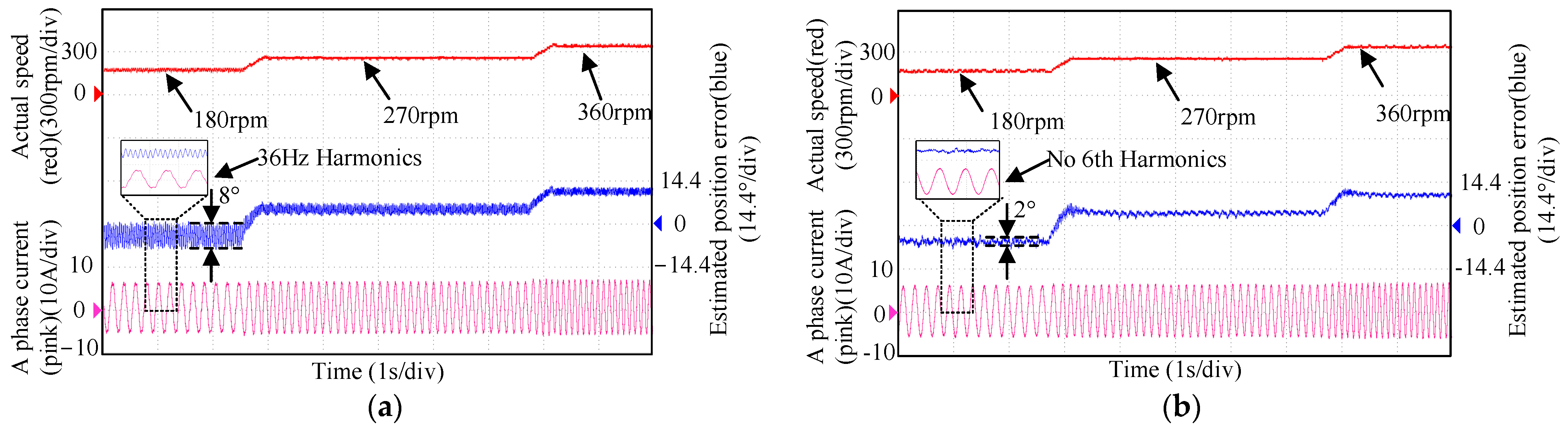
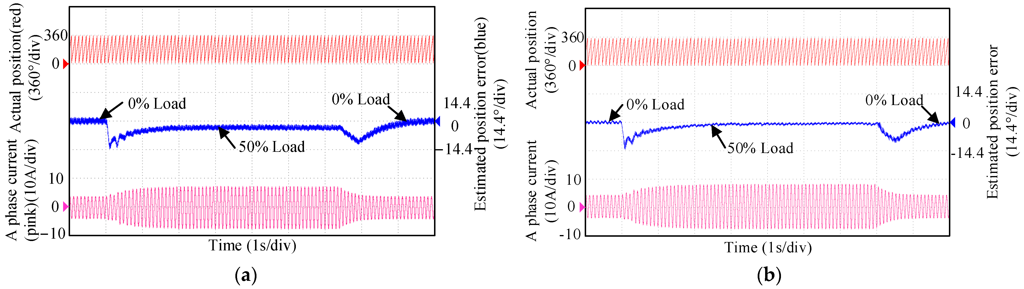
4.2. Experimental Results and Analysis

Figure 9 shows a comparison of the experimental results of the dq-axis current before and after adding dead-time compensation at the 300 rpm and 0% load condition. It can be seen that the d-axis and q-axis currents have a large sixth harmonic component before dead-time compensation, where the amplitude of the harmonics in the q-axis current reaches 0.4 A. The resulting harmonics seriously affect the performance of the motor. However, after adding the ADALINE dead-time compensation, the harmonic amplitude of the dq-axis current drops to less than 0.02 A. The current oscillation caused by the dead time effect is basically eliminated. At the same time, the torque ripple of the motor resulting from the dead time effect is also basically eliminated.
Figure 10 shows the position error spectrum analysis of the motor at 300 rpm with the load going from 0 to 50% of the rated load and then down to 0. As can be seen, before adding dead-time compensation, the observed position of the motor fluctuates considerably, with position fluctuations reaching around 3°, and the main frequency of harmonics is 60 Hz. However, with dead-time compensation, the estimated position fluctuations are obviously reduced and the sixth harmonic is largely eliminated. It is proved that the proposed dead-time compensation algorithm has a good compensation ability for sixth harmonics.
Figure 11 shows the comparison of the position error, speed, and phase current waveforms under a 30% rated load and at 180 rpm, 270 rpm, and 360 rpm, respectively, before and after adding dead-time compensation. As can be seen when the motor running speed is 180 rpm, the current distortion is more serious. And the position estimation amplitude of the sixth harmonic is large, reaching 8°, which seriously affects the operation performance of the motor. After adding the dead-time compensation, as shown in Figure 10, the sixth harmonic is effectively suppressed, and the fluctuation amplitude of the position estimation error is reduced to less than 2°. The validity of the proposed ADALINE dead-time compensation algorithm is proven under different speed conditions.
Figure 12 shows the position error and current waveform of the motor at 300 rpm with the load going from 0 to 50% of the rated load and then down to 0. As shown in Figure 12, the observed position of the motor fluctuates greatly, the position fluctuation reaches about 3°, and the main frequency of harmonics is 60 Hz without the proposed dead-time compensation. After adding the proposed dead-time compensation, the fluctuation amplitude of the position observation error is greatly decreased under different load conditions with dead-time compensation. The effectiveness of the proposed ADALINE dead-time compensation algorithm is proven under different load conditions.
This above experimental results can verify the effectiveness and practicality of the proposed reduced-order observer-based sensorless control method for an SynRM drive combined with the ADALINE dead-time compensation algorithm under different load and speed conditions. The ADALINE dead-time compensation algorithm has a good compensation effect for the sixth harmonics caused by the dead time effect. At the same time, the precision of the observed position and speed is improved. Accordingly, the operation performance of the sensorless SynRM drives is also improved.

5. Conclusions

With respect to the problem of the significant inverter dead time effect on the control performance of sensorless SynRM drives at low speed, this paper proposed a reduced-order observer-based sensorless control method for SynRM drives combined with the ADALINE dead-time compensation. Firstly, the reduced-order observer-based sensorless control method was studied, the parameters of which are easy to adjust compared to the full-order observer method. On this basis, the dead-time compensation strategy using ADALINE filters was proposed to reduce the effect of voltage harmonics on the observation performance of the reduced-order observer. The ADALINE filter makes the estimated coefficient close to the harmonic coefficient of the real voltage by neuronal learning. With ADALINE filters, the sixth current harmonic can be successfully filtered out by compensating for the voltage directly and fitting the current to compensate the voltage. The proposed method optimizes the sensorless operation performance of SynRM drives at low speeds. The experimental results show that the reduced-order observer-based sensorless control method combined with ADALINE dead-time compensation has good performance at a low speed. The position estimation fluctuations of the reduced-order observer are reduced and the observer operates more stably at a low speed.

Author Contributions

Methodology, R.G.; Software, J.W.; Validation, L.L. and Z.W.; Formal analysis, J.W.; Investigation, Z.W. and X.Z.; Resources, L.L., R.G. and G.W.; Writing—original draft, X.Z.; Writing—review & editing, S.L.; Visualization, S.L.; Supervision, G.W. All authors have read and agreed to the published version of the manuscript.

Funding

This research received no external funding.

Data Availability Statement

Data are contained within the article.

Conflicts of Interest

Authors Liangnian Lv, Rui Guo, Jinpeng Wang and Shulin Li were employed by the company Gold wind Sci & Tech Co., Ltd. The remaining authors declare that the research was conducted in the absence of any commercial or financial relationships that could be construed as a potential conflict of interest.

References

  1. Foti, S.; De-Caro, S.; Scimone, T.; Testa, A.; Danilo-Tornello, L.; Scelba, G.; Cacciato, M. Rotor Position Error Compensation in Sensorless Synchronous Reluctance Motor Drives. IEEE Trans. Power Electron. 2022, 37, 4442–4452. [Google Scholar] [CrossRef]
  2. Credo, A.; Di-Leonardo, L.; Parasiliti-Collazzo, F.; Tursini, M. The Impact of the Control Strategy in Flux Observer Based Sensorless Control of Synchronous Reluctance Motors. IEEE Access 2021, 9, 156380–156391. [Google Scholar] [CrossRef]
  3. Hu, Y.; Chen, B.; Xiao, Y.; Shi, J.; Li, X.; Li, L. Rotor Design and Optimization of a Three-Phase Line-Start Synchronous Reluctance Motor. IEEE Trans. Ind. Appl. 2021, 57, 1365–1374. [Google Scholar] [CrossRef]
  4. Mirazimi, M.S.; Kiyoumarsi, A. Magnetic field analysis of SynReland PMASynRel machines with hyperbolic flux barriers using conformalmapping. IEEE Trans. Transp. Electrif. 2020, 6, 52–61. [Google Scholar] [CrossRef]
  5. Burkhart, B.; Klein-Hessling, A.; Ralev, I.; Weiss, C.P.; De Doncker, R.W. Technology research and applications of switched reluctance drives. CPSS Trans. Power Electron. Appl. 2017, 2, 12–27. [Google Scholar] [CrossRef]
  6. Mu, J.; Ge, X.; Chang, Y.; Liang, G. Speed-Sensorless Control of Induction Motor Drives with a FCS-Based Estimation Scheme. CPSS Trans. Power Electron. Appl. 2023, 8, 278–289. [Google Scholar] [CrossRef]
  7. Zhang, G.; Xiang, R.; Wang, G.; Li, C.; Bi, G.; Zhao, N.; Xu, D. Hybrid Pseudorandom Signal Injection for Position Sensorless SynRM Drives With Acoustic Noise Reduction. IEEE Trans. Transp. Electrif. 2022, 8, 1313–1325. [Google Scholar] [CrossRef]
  8. Zhang, G.; Wang, G.; Yuan, B.; Liu, R.; Xu, D. Active disturbancerejection control strategy for signal injection-based sensorless IPMSMdrives. IEEE Trans. Transport. Electrif. 2018, 4, 330–339. [Google Scholar] [CrossRef]
  9. Xiao, D.; Nalakath, S.; Rotilli-Filho, S.; Fang, G.; Dong, A.; Sun, Y. Universal Full-Speed Sensorless Control Scheme for Interior Permanent Magnet Synchronous Motors. IEEE Trans. Power Electron. 2021, 36, 4723–4737. [Google Scholar] [CrossRef]
  10. Bolognani, S.; Ortombina, L.; Tinazzi, F.; Zigliotto, F. Model sensitivity of fundamental-frequency-based position estimators for sensorless pm and reluctance synchronous motor drives. IEEE Trans. Ind. Electron. 2018, 65, 77–85. [Google Scholar] [CrossRef]
  11. Gao, F.; Yin, Z.; Bai, C.; Yuan, D.; Liu, J. A Lag Compensation-Enhanced Adaptive Quasi-Fading Kalman Filter for Sensorless Control of Synchronous Reluctance Motor. IEEE Trans. Power Electron. 2022, 37, 15322–15337. [Google Scholar] [CrossRef]
  12. Wang, S.; Zhang, G.; Wang, Q.; Ding, D.; Bi, G.; Li, B.; Wang, G.; Xu, D. Torque Disturbance Compensation Method Based on Adaptive Fourier-Transform for Permanent Magnet Compressor Drives. IEEE Trans. Power Electron. 2023, 38, 3612–3623. [Google Scholar] [CrossRef]
  13. Pasqualotto, D.; Rigon, S.; Zigliotto, M. Sensorless Speed Control of Synchronous Reluctance Motor Drives Based on Extended Kalman Filter and Neural Magnetic Model. IEEE Trans. Ind. Electron. 2023, 70, 1321–1330. [Google Scholar] [CrossRef]
  14. Zhang, Z. Sensorless Back EMF Based Control of Synchronous PM and Reluctance Motor Drives—A Review. IEEE Trans. Power Electron. 2022, 37, 10290–10305. [Google Scholar] [CrossRef]
  15. Gao, F.; Yin, Z.; Bai, C.; Yuan, D.; Liu, J. Speed Sensorless Control Method of Synchronous Reluctance Motor Based on Resonant Kalman Filter. IEEE Trans. Ind. Electron. 2023, 70, 7627–7641. [Google Scholar] [CrossRef]
  16. Yousefi-Talouki, A.; Pescetto, P.; Pellegrino, G.; Boldea, I. Combined active flux and high-frequency injection methods for sensorless direct-flux vector control of synchronous reluctance machines. IEEE Trans. Power Electron. 2018, 33, 2447–2457. [Google Scholar] [CrossRef]
  17. Varatharajan, A.; Pellegrino, G. Sensorless Synchronous Reluctance Motor Drives: A General Adaptive Projection Vector Approach for Position Estimation. IEEE Trans. Ind. Appl. 2020, 56, 1495–1504. [Google Scholar] [CrossRef]
  18. Tuovinen, T.; Hinkkanen, M.; Luomi, J. Analysis and Design of a Position Observer With Resistance Adaptation for Synchronous Reluctance Motor Drives. IEEE Trans. Ind. Appl. 2013, 49, 66–73. [Google Scholar] [CrossRef]
  19. Tang, Z.; Akin, B. Suppression of Dead time Distortion Through Revised Repetitive Controller in PMSM Drives. IEEE Trans. Energy Convers. 2017, 32, 918–930. [Google Scholar] [CrossRef]
  20. Wang, G.; Yang, R.; Xu, D. DSP-Based Control of Sensorless IPMSM Drives for Wide-Speed-Range Operation. IEEE Trans. Ind. Electron. 2013, 60, 720–727. [Google Scholar] [CrossRef]
  21. Wang, Q.; Liu, S.; Zhang, G.; Ding, D.; Li, B.; Wang, G.; Xu, D. Zero-Sequence Voltage Error Elimination Based Offline VSI Nonlinearity Identification for PMSM Drives. IEEE Trans. Transp. Electrif. 2023, 10, 55–66. [Google Scholar] [CrossRef]
  22. Qiu, T.; Wen, X.; Zhao, F. Adaptive-Linear-Neuron-Based Dead time Effects Compensation Scheme for PMSM Drives. IEEE Trans. Power Electron. 2016, 31, 2530–2538. [Google Scholar] [CrossRef]
  23. Yong-Kai, L.; Yen-Shin, L. Dead-time Elimination of PWM-Controlled Inverter/Converter Without Separate Power Sources for Current Polarity Detection Circuit. IEEE Trans. Ind. Electron. 2009, 56, 2121–2127. [Google Scholar] [CrossRef]
  24. Chen, L.; Peng, F.Z. Dead-time elimination for voltage source inverters. IEEE Trans. Power Electron. 2008, 23, 574–580. [Google Scholar] [CrossRef]
  25. Liu, K.; Zhu, Z.Q. Online Estimation of the Rotor Flux Linkage and Voltage-Source Inverter Nonlinearity in Permanent Magnet Synchronous Machine Drives. IEEE Trans. Power Electron. 2014, 29, 418–427. [Google Scholar] [CrossRef]
  26. Sam-Young, K.; Wootaik, L.; Min-Sik, R.; Seung-Yub, P. Effective Dead time Compensation Using a Simple Vectorial Disturbance Estimator in PMSM Drives. IEEE Trans. Ind. Electron. 2010, 57, 1609–1614. [Google Scholar] [CrossRef]
  27. Kim, S.-Y. Compensation of Dead-Time Effects Based on Adaptive Harmonic Filtering in the Vector-Controlled AC Motor Drives. IEEE Trans. Ind. Electron. 2007, 54, 1768–1777. [Google Scholar] [CrossRef]
  28. Tuovinen, T.; Hinkkanen, M.; Harnefors, L.; Luomi, J. Comparison of a Reduced-Order Observer and a Full-Order Observer for Sensorless Synchronous Motor Drives. IEEE Trans. Ind. Appl. 2012, 48, 1959–1967. [Google Scholar] [CrossRef]
  29. Wang, L.; Zhu, Z.Q.; Bin, H.; Gong, L.M. Current Harmonics Suppression Strategy for PMSM With Nonsinusoidal Back-EMF Based on Adaptive Linear Neuron Method. IEEE Trans. Ind. Electron. 2020, 67, 9164–9173. [Google Scholar] [CrossRef]
Figure 1. Coordinate system of the SynRM drive.
Energies 17 01693 g001
Figure 2. Structure of the reduced-order observer.
Energies 17 01693 g002
Figure 3. Block diagram of sensorless SynRM drives with ADALINE dead-time compensation.
Energies 17 01693 g003
Figure 4. The circuit diagram of three-phase PWM inverter.
Energies 17 01693 g004
Figure 5. ADALINE-based voltage decomposer.
Energies 17 01693 g005
Figure 6. Amplitude-frequency response of ADALINE.
Energies 17 01693 g006
Figure 7. ADALINE algorithm for voltage filtering based on current information.
Energies 17 01693 g007
Figure 8. Experimental platform.
Energies 17 01693 g008
Figure 9. Experimental results before and after q-axis voltage filtering at 300 rpm and 0% load. (a) Without dead-time compensation. (b) With dead-time compensation.
Energies 17 01693 g009
Figure 10. Position error spectral analysis of motor running at 300rpm with 50% load. (a) Without dead-time compensation. (b) With dead-time compensation.
Energies 17 01693 g010
Figure 11. Experimental results position errors at 30% load and different speeds. (a) Without dead-time compensation. (b) With dead-time compensation.
Energies 17 01693 g011
Figure 12. Experimental results with the motor running at 300 rpm and the load rising from 0 to 50% and then down to 0. (a) Without dead-time compensation. (b) With dead-time compensation.
Energies 17 01693 g012
Table 1. SynRM Parameters.
ParametersValue
Rated power (kW)3
Rated current (A)7.6
Rated voltage (V)360
Paris of poles2
Rated speed (r/min)3000
Phase resistance (Ω)0.524
d-axis inductance (mH)51
q-axis inductance (mH)19
Disclaimer/Publisher’s Note: The statements, opinions and data contained in all publications are solely those of the individual author(s) and contributor(s) and not of MDPI and/or the editor(s). MDPI and/or the editor(s) disclaim responsibility for any injury to people or property resulting from any ideas, methods, instructions or products referred to in the content.

