Review

Underground Gas Storage in Saline Aquifers: Geological Aspects

by
Barbara Uliasz-Misiak
1,* and
Jacek Misiak
2
1
Faculty of Drilling, Oil and Gas, AGH University of Krakow, al. A. Mickiewicza 30, 30-059 Krakow, Poland
2
Faculty of Geology, Geophysics, and Environmental Protection, AGH University of Krakow, al. A. Mickiewicza 30, 30-059 Krakow, Poland
*
Author to whom correspondence should be addressed.
Energies 2024, 17(7), 1666; https://doi.org/10.3390/en17071666
Submission received: 9 February 2024 / Revised: 27 March 2024 / Accepted: 28 March 2024 / Published: 30 March 2024
(This article belongs to the Special Issue Advanced Methods for Hydrogen Production, Storage and Utilization)

Abstract

:
Energy, gases, and solids in underground sites are stored in mining excavations, natural caverns, salt caverns, and in the pore spaces of rock formations. Aquifer formations are mainly isolated aquifers with significant spreading, permeability, and thickness, possessing highly mineralized non-potable waters. This study discusses the most important aspects that determine the storage of natural gas, hydrogen, or carbon dioxide in deep aquifers. In particular, the selection and characterization of the structure chosen for underground storage, the storage capacity, and the safety of the process are considered. The choice of underground sites is made on the basis of the following factors and criteria: geological, technical, economic, environmental, social, political, or administrative–legal. The geological and dynamic model of the storage site is then drawn based on the characteristics of the structure. Another important factor in choosing a structure for the storage of natural gas, hydrogen, or carbon dioxide is its capacity. In addition to the type and dimensions of the structure and the petrophysical parameters of the reservoir rock, the storage capacity is influenced by the properties of the stored gases and the operating parameters of the storage facility. Underground gas storage is a process fraught with natural and technical hazards. Therefore, the geological integrity of the structure under consideration should be documented and verified. This article also presents an analysis of the location and the basic parameters of gas storage and carbon dioxide storage facilities currently operating in underground aquifers. To date, there have been no successful attempts to store hydrogen under analogous conditions. This is mainly due to the parameters of this gas, which are associated with high requirements for its storage.

1. Introduction

The rock formations beneath the Earth’s surface can be used in a variety of ways. The main use of rock formations is mineral extraction. In addition to this, the rock mass can be used for a range of different purposes, from installing transport infrastructure, utilities, and utility facilities in the rock to waste disposal and the storage of substances and fuels. The space below the Earth’s surface makes it possible to locate facilities there that are difficult, impossible, environmentally damaging, or expensive to place on the actual surface. In addition, rock formations provide natural protection (including mechanical and thermal protection) against the effects of the external environment. An important feature of underground facilities, which affects the safety of their use, is that the access points to these facilities are small and easily secured [1]. The rock mass is used for various purposes. It can provide a site for industrial, storage, or utility facilities, road, rail transport, storage, and the disposal of substances and waste [2]. At the shallowest depths (up to 40 m), road tunnels, car parks, offices, and warehouses are located, as well as cultural and recreational facilities and underground and rail stations. At depths of 250–3000 m, the underground storage of various substances is carried out, for example, natural gas, energy, and carbon dioxide [1].
Humanity is currently facing the challenge of mitigating climate change related to greenhouse gas emissions [3]. To reduce the amount of greenhouse gases (especially carbon dioxide), it is necessary to develop new technologies that significantly improve energy efficiency, low-carbon production, and also energy and gas storage [4]. Ensuring a reliable energy supply system requires the storage of both energy and energy-related products (e.g., CO2 via carbon dioxide capture and storage (CCS)) in various forms, quantities, and time scales. Underground facilities are used to store natural gas temporarily (UGSs). The underground storage of hydrogen is at an early stage of development. Green hydrogen produced by electrolysis using renewable energy sources (RESs) will allow for the storage of surplus energy. Hydrogen storage will enable increased energy production and also sustainable access to renewables [5,6].
There are two types of H2 storage: physical and chemical (material) methods. Hydrogen can be stored on the surface (in tanks and in natural gas grids) and underground in geological structures (physical method) [7]. Chemical hydrogen storage refers to the process of storing hydrogen through chemical reactions, typically involving compounds that can release or absorb hydrogen. Among different hydrogen storage materials, ammonia bore is considered a promising candidate for chemical hydrogen storage [8,9,10].
The underground storage of energy, gases, and substances is located in mining excavations, natural caverns, salt caverns, and pore spaces in rock formations. Storage can be carried out in the mining excavations of various raw materials in poorly permeable rock formations. Underground storage sites can be located in sedimentary (clay, carbonate, salt, or coal seams), magmatic, and metamorphic rocks. Most commonly, abandoned mines in the above-mentioned rock formations are adapted for underground storage facilities [11]. Due to the nature of salt rocks (salt is impermeable), they provide a suitable environment for the storage of gases, liquids, and solids. Artificially constructed salt caverns have been used for the storage of energy carriers, not only fossil fuels (natural gas, oil, and refined fuels and liquefied gas) but also hydrogen storage. Underground oil and fuel storage facilities exist in the USA, Germany, France, Canada, and Poland [12].
Salt caverns, depleted gas fields, and aquifers are considered as potential sites for underground hydrogen storage (UHS) [13,14,15,16]. However, the previous experience with underground hydrogen storage on an industrial scale is limited to salt caverns [17,18,19].
In addition to caverns in the rock mass created through mining activities, there are natural voids in the rocks that can be used to store energy, gases, and solids. Storage facilities are located in aquifers and hydrocarbon deposits [20,21,22]. The underground storage of carbon dioxide is a technology that has been developed since the 1990s [23,24,25]. The following geological structures have been proposed for underground CO2 storage: depleted oil and gas fields, exploited oil fields (enhanced oil recovery methods), unexploited coal seams (in combination with methane extraction), and deep aquifers [26,27,28,29]. At present, hydrogen storage in porous rock formations is at the research and testing stage. The first test facilities have been commissioned in depleted gas fields in Austria and Argentina [18,19].
The use of aquifers for underground gas storage is an issue that is currently crucial for energy security (natural gas storage) and the implementation of a zero-carbon economy. In this article, the authors have attempted to present the key aspects that affect underground gas storage in aquifers on an industrial scale. The purpose of this article is not to describe in detail the technology of gas storage in aquifers but rather to identify the important aspects and geological conditions of underground storage. Particular attention was paid to the selection and characterization of the structure chosen for underground storage, its storage capacity, and the safety of the process. Gas storage facilities located in aquifers around the world are also presented.

2. General Characteristics of Aquifer Storage

The geological structures indicated for the underground storage of natural gas, hydrogen, or carbon dioxide must be characterized by suitable rock successions in the geological structure (reservoir rock covered with sealing rock); a suitable depth, thickness, and capacity of the storage formation; tightness of the site storage; no adverse impact of the stored substance; and no adverse impact of natural and anthropogenic phenomena occurring in the rock mass [22,30].
Geological structures in porous rocks are considered as sites for underground gas storage, i.e., deep saline aquifers and depleted (saturated) oil and gas reservoirs. These structures occur in sedimentary basins in the form of geological traps where hydrocarbon deposits have accumulated or in the form of elevated anticlines in the case of aquifers.
Saline aquifers are mainly isolated, water-bearing formations of significant extent, permeability, and thickness [31], with highly mineralized and non-potable water [32]. Aquifers characteristically have a potentially large storage capacity. Underground storage in porous rocks takes advantage of the voids (between mineral grains or fractures) found in sedimentary rocks. The rock formation to be used as gas storage must have high porosity and permeability. Porosity determines the amount of free space in the rock that can be used, for example, for gases. Permeability, on the other hand, indicates the ability of gases to flow through the rock formation and also determines the rate at which gases are injected and extracted. The rock most suitable for the use of its pore space is sandstone as it has communicating pores and possesses permeability that allows gases to migrate and form accumulations [33]. For this reason, sandstone formations are considered to be the most significant prospect for underground storage. The pore space can store natural gas, hydrogen, and sequestered carbon dioxide [30,34,35].
An important factor determining the possibility of transforming the geological structure into a storage site is the isolation of reservoir rocks with a virtually impermeable caprock with a thickness of at least several meters, which limits migration outside the storage formation [36,37,38,39]. Rocks with the best sealing properties are salts, anhydrites, and clay rocks. A rock formation dedicated for gas storage should not exhibit disjunctive tectonics because the presence of discontinuities in the rocks may provide leakage paths for gas toward the surface. In addition, the various gases have different physical and chemical properties that affect the underground storage processes. Of the gases considered, hydrogen has the highest mobility and permeability due to its low molecular mass, high dynamic viscosity, low critical density, and ability to diffuse more rapidly in the rock matrix. Therefore, hydrogen is the gas that will be the most difficult to store and to which the greatest restrictions should be applied in the choice of storage site location [22].
Depending on the geological conditions of the rock formation, the aquifers are open or confined (structural traps). An open structure is one that is not separated from the entire aquifer by structural or lithological boundaries. For example, a closed or partially closed structure is a structure separated from the aquifer by faults. In an open aquifer, the injected gases can spread laterally (largely unobstructed), provided there are no lateral flow boundaries (for example, faults) in the reservoir. Initially, the injected gas will migrate upward under buoyancy until it reaches the sealing overburden, under which it can spread laterally. In closed aquifers (structural traps), the gas is held in a confined space by buoyancy forces under impermeable rock. A key advantage of structural traps is that gas migration in the reservoir is limited to its size [40]. In the case of a closed structural trap, which is limited in size, gas injection results in an increase in pressure (fracturing and capillary). Therefore, the pressure value should be kept below the maximum pressure (fracturing pressure) to preserve the mechanical integrity of the storage site from tensile or shear damage to the rock and/or reactivation of existing fractures and faults [41,42].
Various trapping mechanisms are at work during hydrogen storage and carbon sequestration (Figure 1). CO2 trapping mechanisms have been extensively studied [43,44,45] and have also been recognized in studies performed at carbon dioxide injection sites [45,46]. Gases injected into an aquifer formation migrate upward under buoyancy forces and, if a sealing overburden is present, are trapped in the geological structure (structural or stratigraphic trapping) [31]. The same mechanism results in the trapping of hydrogen [47] and natural gas in structural traps [48]. The dissolution of carbon dioxide is indicated as one of the key trapping mechanisms [49,50,51]. Hydrogen can also dissolve in water, which, on the one hand, translates into trapping capacity, but on the other hand, reduces the amount of H2 withdrawal [47,52]. Capillary or residual trapping will immobilize gases in the pore space via capillary forces [6,53]. The injected CO2 will dissolve in water and initiate a variety of geochemical reactions; these reactions between dissolved carbon dioxide and the rocks of the storage formation will occur on scales of hundreds to thousands of years [31].
Solubility in water is highest for carbon dioxide, lower for methane, and very low for hydrogen; therefore, this parameter is favorable for the storage of carbon dioxide. Part of the CO2 will dissolve in the water that fills the porous rocks of the underground storage, and part will react with the rock matrix and become permanently trapped in it. In the case of hydrogen, its loss, because of its very low solubility, can be practically ignored [22,54].
The injection process and flow characteristics of CO2 are impacted by the solubility of gas and brine in three ways: brine’s density appears to increase initially when CO2 dissolves in it; this causes a reaction with water to generate an acid; and ultimately, gas dissolves into water to raise the brine’s mineralization [55,56]. The solubility of CO2 depends mainly on pressure, temperature, total dissolved solids, and brine composition. Carbon dioxide solubility generally rises with pressure and falls with temperature and brine mineralization [57].
The geochemical interactions of the gases under consideration with the subterranean environment, the rock matrix, and the water are very important in the operation of underground storage sites. The scale and speed of the reactions depend on the presence of reactive minerals such as feldspar, magnesium, and ferruginous minerals in the storage formation. Mineral trapping can both positively and negatively affect CO2 storage. Mineral dissolution and trapping can permanently trap more than 90% of the injected CO2 in the aquifer in the form of the carbonates, calcite (CaCO3), magnesite (MgCO3), dolomite (MgCO3 CaCO3), dawsonite (NaAlCO3(OH)2), and siderite (FeCO3) [58,59]. Hydro- and geochemical interactions can positively or negatively affect the reservoir rock or the sealing overburden. The precipitation or dissolution of chemical components can cause changes in the petrophysical parameters, especially in the near-wellbore zone or in overburden rocks [60,61,62]. In addition, in the case of underground hydrogen storage, it will be trapped by the following processes: (a) structural/stratigraphy trapping, (b) residual/capillary trapping, (c) mineral trapping, and (d) dissolution trapping [13,47,63].
The scale of geochemical interactions will vary between gases. In some reservoir types, gases such as H2S can be formed in reactions with methane. In the case of underground carbon dioxide storage, the impacts will be determined by the reactivity of the rock matrix with the gas dissolved in water to form acidic calcium carbonate. During underground hydrogen storage (UHS), geochemical interactions can occur that involve stored hydrogen, cushion gas, reservoir fluids, and minerals [64,65]. These reactions may result in the conversion of hydrogen to other gases (methane and hydrogen sulfide), which will result in the loss of stored hydrogen. Additionally, geochemical processes have the potential to reduce hydrogen purity. Similar to CO2 storage, geochemical reactions can also cause changes in the porosity and permeability of reservoir rocks.
As a result of the modification of petrophysical parameters, the geomechanical properties of the storage formation may change. The changes in geomechanical properties can lead to a reduction in the integrity of the overburden rocks [19,66]. The most significant geochemical interactions that are similar to CO2 storage are aqueous reactions and mineral dissolution–precipitation reactions [65,66]. Dissolution–precipitation reactions that occur in porous rocks during hydrogen storage can cause changes in the grain skeleton and cements. These changes can increase the elastic and inelastic deformation of the reservoir [67,68].
An important factor to consider during UHS is microbial-induced reactions. The number and type of live microorganisms (such as bacteria) present at the storage site control these reactions. Numerous biotic processes occur in hydrogen storage sites, including methanogenesis, acetogenesis, sulfate reduction, and reduction. Methanogenesis is the conversion of hydrogen to methane and water when it reacts with CO2 in the presence of methanogens [69]. Acetogenesis is a biotic reaction that occurs between H2 and CO2 in the presence of acetogenic bacteria. This reaction results in the formation of acetic acid and water as follows [70]. When sulfate-reducing bacteria are present in the storage formation, sulfate-reducing processes occur, converting H2 and sulfate to hydrogen sulfide [71,72,73]; in the presence of high-salinity brines, it is expected that the action of the reduction bacteria will be slower [74].
Geomechanical impacts on underground gas storage sites will vary. This is primarily due to the different operations of underground hydrogen, methane, and carbon dioxide storage. In the case of CO2 injection, the reservoir pressure will not fluctuate in the same way as at storage sites where hydrogen and methane are injected cyclically. In natural gas storage, cyclic injection and withdrawal will have an effect on a longer time scale. However, in the case of hydrogen storage, a higher injection/withdrawal frequency will result in greater impacts on the reservoir and overburden rocks (intergranular swelling and shrinkage cycles). Due to the current lack of experience with underground hydrogen storage in porous rock, these issues are not fully recognized. The different injection regimes for individual gases will also affect the subsidence/uplift, induced seismicity, and fracture propagation. These phenomena will be most intense in hydrogen stores and will affect the integrity of the overburden or the movement along pre-existing faults [75]. Currently, the effects of cyclic stresses associated with hydrogen storage on porous rocks and faults require further research. UHS operations can take advantage of the experience from other natural gas storage operations, nuclear waste storage, unconventional hydrocarbon production, and geothermal production [76].

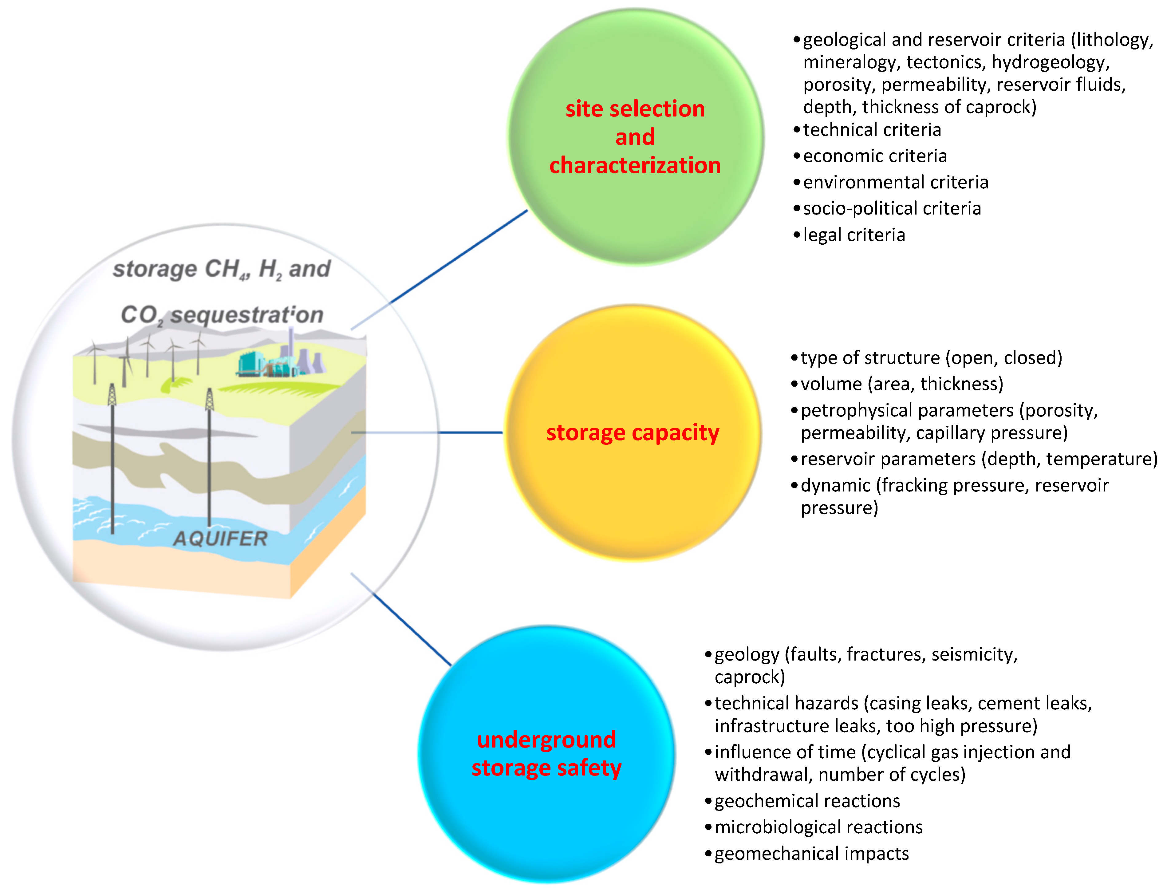
3. Selected Geological Aspects of Gas Storage in Aquifers

Among the many aspects of conditioning the storage of natural gas, hydrogen, or carbon dioxide in deep aquifers, the choice and characteristics of the structure chosen for underground storage, the storage capacity, and the safety of the process are particularly important (Figure 2).

3.1. Selection and Characterization of Potential Gas Storage Sites

A fundamental prerequisite for the success of the underground storage of natural gas, hydrogen, or carbon dioxide is the selection of an appropriate storage site location. The optimal location for underground storage should take into account a number of factors, which play a different role in the subsequent stages of the investment process, particularly when selecting an optimal and safe location for the facility and the operating technology.
The process of constructing underground gas storage facilities is a complex problem. The investment process is closely linked to the stages of geological reconnaissance of a potential gas storage site: identification and screening, selection, and characterization. As a result of geological reconnaissance and site ranking, a storage site location is selected for which design and administrative and legal work are carried out. First, site screening assesses geographical regions or sedimentary basins for the possibility of locating underground storage facilities and identifies prospective areas for the site. Here, all available data (geological and technical) are used; however, surveys are kept to a minimum or are not performed at all. Next, site selection is the ranking of the selected prospective areas for the possibility of developing an underground storage facility and the identification of potential sites for its construction within the prospective area, taking into account the location criteria. As in the case of site screening, all available data are used and a preliminary geological survey (if none is available) is carried out to identify these sites. In Polish terms, this next stage of site characterization is the evaluation of potential locations for a facility and the selection of at least one that meets all location criteria, for which further design work and building permit activities will be carried out. At this stage, all existing data are used, and new data are acquired from a number of geological disciplines. This stage is often further divided into preliminary and detailed characterization [77].
The selection of underground sites is made on the basis of the following factors and criteria: geological, technical, economic, environmental, social, political, or administrative–legal.
To date, no uniform criteria or methodology have been developed for the selection of sites for underground gas storage. The geological structures for underground gas storage are selected considering the parameters of storage capacity, the requirement of a lack of gas migration, and the possibility of achieving the desired yield [78,79]. Additional criteria associated with storage design relate, among other things, to the proper ratio of working capacity to gas cushion (buffer) capacity [80]. Multi-criteria decision-making systems have also been used to identify types of structures for underground gas storage. The analytic hierarchy process method has been used for the screening of hydrocarbon reservoirs, aquifers, and salt caverns [81]. The main criteria used in this model are cost, time, utility, risk, social, and environmental factors [82].
Several publications have focused on the selection of sites for the geological storage of carbon dioxide. However, the literature lacks uniform criteria for the selection of these sites. The studies of different authors have proposed very different methods to select locations for underground CO2 storage sites. Several studies have typified the structures for underground storage through a comparison of the amount of CO2 emitted from large sources with the capacity of pools or reservoirs, usually using a Geographic Information System (GIS) [83,84,85]. Using this type of approach, it is possible to identify large areas of sedimentary basins that are potentially suitable for the location of CO2 storage sites; however, a more detailed approach is needed to identify specific locations. This is performed on the basis of the criteria, geological, depositional, and technical, that a geological structure should meet in order to be considered a storage site for this gas and taking into account the specific characteristics of carbon dioxide. In most methodologies, the criteria used to select structures as CO2 storage sites are the depth of the reservoir rocks; their thickness, porosity, and permeability; the mineralization of the water; and whether there is a sufficiently thick overburden of rocks with poor permeability. These criteria allow for the pre-selection of structures characterized not only by adequate capacity but also by the ability to safely carry out the storage process [40,86,87,88,89]. Some methodologies also take into account additional criteria (technical, environmental, or sociological) [77,90]. Some authors have used indicators such as positive, cautionary, and negative [40,86,91], and others have scored the sites (0—worst; 1—best) [92] or used scales [90], which are assigned to each criterion. The selection of structures for underground storage sites has also involved the use of workflows [87,93]. A method based on such a scheme was applied to typify underground carbon storage sites beneath the North Sea floor in north-east Scotland [94] and in the Utsira Formation. The aforementioned methodologies have been used to estimate and classify geological carbon storage sites on different scales (country, sedimentary basin, and storage site) [92,93]. A methodology developed by the National Energy Technology Laboratory in 2017 [77] provides an algorithm for the initial selection, typing, and characterization of geological carbon storage sites contained in CSA Z741 [95]. Some methods for selecting and ranking underground carbon storage sites are based on decision-making systems. For example, Llamas et al. [96,97] proposed the use of a multi-criteria decision-making system, which was based on two groups of criteria: technical criteria (geology, tectonics, hydrogeology, capacity, and state of phase of CO2) and socio-economic criteria (quality and quantity of geological data, CO2 sources, location, population density, and environmental aspects). The ANP method has been used to select structures suitable for the geological storage of CO2 in China [98]. A method using fuzzy logic was also developed to type carbon storage sites [99]. Another method, categorized as a multi-criteria decision-making method, TOPSIS, was used to assess suitable locations for CO2 storage sites based on the example of Turkey [100].
Additionally, for the selection of sites for underground hydrogen storage, there are no uniform criteria and methods. The methodologies for the selection of underground hydrogen storage are presented in articles [74,101,102], the HyStories project reports [103], and HyUnder [104]. For the selection of hydrogen storage sites in aquifers, the following criteria were used: reservoir volume, lithology of the overburden, tectonic involvement, depth of the overburden, thickness of the overburden, and the state of exploration [102]. In the HyStories project, underground hydrogen storage sites were selected based on geological and depositional criteria (depth, thickness, type of structure, sedimentation environment, effective porosity, permeability, mineralogy, tectonics, and reservoir fluids, among others) and on general environmental selection criteria (overburden rocks, higher lying aquifers, seismicity, accessibility, subsidence, land ownership, mining rights, regulatory compliance, and acceptability) [103]. The HyUnder project presented a ranking of underground hydrogen storage sites (aquifers, depleted hydrocarbon deposits, salt caverns, decommissioned mines, and pipelines). For each option, the safety, technical feasibility, investment costs, and operation were scored on a scale of 0 to 5. Lewandowska et al. (2018) proposed a methodology for the typing of suitable geological structures (in aquifers, hydrocarbon deposits, and salt structures) for hydrogen storage, based on the AHP method [102]. The methodology was based on geological and operational criteria. Behrouz et al. [101] presented a methodology to select sites for underground hydrogen storage on the basis of the fuzzy Delphi method. Thaysen et al. used a different approach for selecting structures for underground hydrogen storage based on the evaluation of biotic processes [74]. The HyStories project developed a methodology for selecting hydrogen storage sites based on screening (or exclusion) criteria and scoring criteria. The exclusion criteria must be met before a structure can be considered as a potential storage site (e.g., insufficient capacity and lack of sealing or containment). The geological and reservoir criteria and general environmental selection criteria were considered as the scoring criteria. For each of the scoring criteria, the importance of location, capacity, and performance (not applicable; 1: minor for scoring; and 2: major for scoring) was determined [103].
The methods currently used to select structures for underground gas storage vary widely. The optimal location for an underground storage facility should take into account many different factors. These factors play a different role in the subsequent stages of the investment process, especially when selecting the optimal safe location and the operating technology for an underground storage facility. First, the selection of possible underground storage locations should be made on the basis of a predefined set of factors and evaluation criteria. The selected structures should then be subjected to a detailed analysis, based on which the optimal underground storage location is selected. The following factors and criteria can be used to select the location of underground gas storage facilities: geological, technical, economic, environmental, social, political, and administrative–legal. Of these factors and criteria, some are mandatory (precluding the choice of location for an underground storage facility) and some are non-mandatory (determined by the investor in order to assess and select the optimal storage location). Geological exclusion criteria include the too small capacity of the structure in question, too deep or too shallow a structure, a tectonically involved structure (faults), or a structure without confirmed sealing (Table 1). Environmental criteria may also exclude a structure as a gas storage site, such as the location of the structure under a densely populated (urban) area or under important infrastructure (airport or nuclear power plant). A set of properly established criteria forms the basis for assessing and selecting the optimal location for an underground storage facility. The selection of the location should be based on multi-criteria methods allowing for the combined analyses of quantifiable and nonquantifiable criteria. In addition, the risk of bias or manipulation influencing the decision should be eliminated to analyze the impact of changes in individual sub-assessments on the final decision.
Gas storage sites in aquifers can be located at depths from 200 to approximately 3000–3500 m below ground level (b.g.l.). In the case of carbon dioxide injections, the aquifer must be below 800 m depth b.g.l., so that carbon dioxide occurs in the supercritical phase under normal geothermal gradients and pressures. The limitation of the maximum depth at which storage is to be carried out, approximately 3000–3500 m, is related to the costs of injection and the deterioration of petrophysical parameters of reservoir rocks with depth. The limit of the thickness of low-permeable caprock (sealing the storage formation) for natural gas is above 20 m, and for carbon dioxide and hydrogen, it is above 50 m. To ensure proper injectivity, it was assumed that the porosity of natural gas and hydrogen storage formations should be over 10% and more than 15% for CO2. The possibility of a gas flow into storage formation depends on the permeability of the reservoir rock. For effective natural gas and CO2 storage, the rock must possess significant permeability, ideally exceeding 300 mD, and for underground hydrogen storage purposes, permeability should be above 50 mD. Water mineralization affects storage capacity, as gases become more soluble with mineralization. Total dissolved solids exceeding 100 g/L are believed to enhance carbon dioxide underground storage.
Once the location of the underground storage facility has been selected, the next step is to characterize it. Identifying the structure of an aquifer is one of the initial stages in the construction of an underground storage facility for gas. There are geological risks associated with underground gas storage. The geological recognition of structures in saline aquifers is inadequate. Very few geological data and studies are available for these structures at the beginning of the investment process. Therefore, costly exploration and appraisal work are needed to document the geological integrity of the aquifer formation, its ability to store gases under pressure, and to develop the reservoir and geological structure for this underground facility. Additionally, due to environmental constraints, storage in an aquifer is only possible in formations with saline waters (brines) that are tightly isolated from higher-lying, potable groundwater. Usually, knowledge of the location is limited and detailed studies and analyses are required to characterize the following conditions: the geological structural and geodynamic, geological bedrock, hydrogeological, geothermal, geomechanical, and geological engineering. Various survey methods are used for this purpose, including geological, geophysical, geochemical, geomechanical, and drilling methods. On the basis of these, a geological and dynamic model of the storage site is drawn up. The models are used at all stages of the storage site, not only for its characterization but also to verify the accuracy of the gas injection and storage processes. The data resources increase significantly as the investment process progresses.

3.2. Storage Capacity

An important factor in choosing a structure for the storage of natural gas, hydrogen, or carbon dioxide is its capacity. Carbon dioxide storage facilities must have the largest capacity. The volumes required for the storage of natural gas and hydrogen are smaller. In addition to the type (closed or open) and dimensions of the structure (e.g., surface area and thickness), the petrophysical parameters of the reservoir rock, the properties of the stored gases, and the storage operation parameters (injection pressure and amount of cushion gas) influence the storage capacity.
Storage capacity assessments have been and are being carried out using different methods and assumptions. The first capacity assessments were based on the assumption that CO2 storage in deep aquifers was associated with structural and/or stratigraphic trapping [106,107,108]. The capacity was calculated on the basis of pore volume, taking into account the density of carbon dioxide under reservoir conditions and assuming that only part of the reservoir could be occupied by the injected carbon dioxide [109]. Very large approximations were used in these calculations, and the input data used were generalized. A major difficulty encountered in these estimates was in determining the efficiency of carbon dioxide storage. Efficiency factors have been proposed based on various factors including the hydrogeological parameters of the aquifer and its type [23,110], the trapping structure type (closed/semi-open/open), residual CO2 saturation [111,112], the reservoir parameters (depth, temperature, permeability, and capillary pressure) [113], and the lithological types of reservoir rocks [114,115]. The volumetric methods did not take into account any dynamic phenomena that may occur during the injection of CO2 into the aquifer. A factor that can reduce the storage capacity of a structure is the allowable increase in pressure within it as a result of the injection of CO2. This is the most important factor when storing CO2 in closed structures and is the principal determinant of storage safety [40]. It is considered in two forms: fracture pressure and capillary pressure. The storage capacity calculated taking the pressure of the increase into account is called the dynamic capacity [116,117]. This capacity is estimated with the numerical simulation of the CO2 storage process (e.g., see [118,119,120,121]). The effect of increased pressure in the structural traps has a significant effect on the amount of gas storage than that compared to open and semi-closed systems [122,123]. On the other hand, modeling studies have shown that increased pressure can also partially reduce the storage capacity of open systems [51,121]. Based on the above considerations, it can be concluded that the effective reservoir capacity is not only limited by the pore volume of the reservoir rock [41].
Underground hydrogen storage technology is at an early stage of development compared to CCS technology. Experience from CO2 storage has been used in hydrogen storage capacity assessments, which in porous rock have been made using static or dynamic methods. Static assessments are based on determining the volume of pore space that can be filled with stored hydrogen [15]. Static capacity can be assessed on a regional scale or for individual geological structures, e.g., [124]. However, dynamic storage capacity is most commonly determined at the scale of structures using hydrodynamic modeling methods, e.g., [125,126]. Estimates are also made in a similar way to carbon dioxide using volumetric methods [127,128]. When estimating the amount of hydrogen that can be stored in an aquifer, the density of hydrogen under reservoir conditions and the need for a cushion gas are taken into account. This cushion gas plays an important role as a buffer, as it is injected into brine aquifers mainly through the displacement of the brine and is accompanied by high pressures. The required ratio of buffer gas to working gas depends largely on geological parameters, including the depth of the reservoir, the shape of the trap, and the permeability of the reservoir [129,130]. For hydrogen storage in aquifer structures, the amount of the cushion gas should range from 45 to 80% [16,127,131]. Hydrogen storage capacity has also been estimated using numerical simulation methods [125,132,133].
Many estimates of carbon dioxide storage capacity in aquifers have been made on a global scale. The scatter in the results of the assessments is large (200–56,000 Pg), e.g., the IPCC Report [31] states that the global storage capacity in deep aquifers is at least 1000 Pg. For Europe, CO2 storage capacity was estimated at 30–577 Pg [90,134,135]. The discrepancies are due to the different assumptions made in conducting these assessments and the unreliability of the parameters. Capacity assessments have also been carried out at the scale of individual countries, for example, the potential for CO2 storage in aquifers in the United States ranges between 1600 Gt CO2 and 20,000 Gt CO2 [13,136], and for aquifers in Poland, storage capacity was estimated at 52,200–209,000 Mt CO2 depending on storage efficiency [109]. Storage capacity assessments in selected sedimentary basins in China (Bohai Bay Basin, Beibu Gulf Basin, and Yinggehai Basin) indicated that the potential for CO2 storage was approximately 39.98, 53.22, and 13.37 Gt [137].
The largest hydrogen storage capacity is characterized by structures in aquifers. The storage capacity of depleted hydrocarbon reservoirs is determined by the size of the reservoir [138]. To date, no global assessments of hydrogen storage capacity in geological structures have been made. The assessments of hydrogen storage potential have been carried out in aquifers and in depleted oil and gas fields (in natural gas storage facilities) in the European Union and four neighboring countries. Existing and planned natural gas storage facilities located in aquifers and gas fields in Europe have a total capacity of 664 TWh and 747 TWh, respectively [124]. The hydrogen storage capacity of more than 800 traps in porous rocks was estimated at 6850 TWh offshore (19,000 TWh with offshore and onshore) [139].

3.3. Safety of Gas Storage in Aquifers

The greatest hazard associated with the operation of gas storage facilities is the leakage of gas into the surrounding rock formations. Gases from outside the storage site can enter in the form of a leak or as an emergency escape. Gas leakage from the storage site can occur through leaking wells (possibly through their wellheads) caused, for example, by the corrosion of casing or poor cementing. Fractures, discontinuities (faults), or overburden rocks can cause gas to leak out of the storage site. Although the original geologic recognition should have indicated their tightness, the overburden rocks may be leaking.
Natural (due to geological conditions) and technical risks may occur during the process of underground gas storage. A basic prerequisite is the selection of a suitable structure for underground storage and its detailed characterization. The geological integrity of the structure must be checked and documented on the basis of surveys and available archival data. In the case of water-bearing formations, this tightness may be questionable and require thorough investigation and identification. Poorly permeable rocks with a thickness of several meters or more (claystones, siltstones, and evaporates) must lie directly above the storage formation. Sealing caprocks must be continuous both horizontally and vertically. They should have a thickness that will prevent the loss of containment due to increased injection pressure and fracturing pressure.
The cyclic injection and withdrawal of natural gas and hydrogen can lead to several phenomena that will affect the integrity of the underground site storage [19,37,140,141,142]. The introduction of gases into storage formation will lead to an increase in pressure and, thus, to changes in the stress pattern (cf. [143,144,145]). Cyclic stress fluctuations in the vicinity of the well, within the reservoir, and in faults can cause compaction of the reservoir horizon, leading to reduced porosity and reduced reservoir fluid flow, subsidence, reactivation of faults, or microseismicity [143,146,147,148]. The magnitude of the various phenomena that occur in underground storage sites will vary over time and therefore affect the integrity of the storage complex [149,150].
The injection of large volumes of gas can damage the integrity and seal the overburden rocks [151]. Deformations in storage formation, caprock, and faults have been shown to occur due to the swelling of clay minerals. This will affect the long-term stability and safety of underground storage [152,153]. Additionally, geochemical reactions (dissolution/precipitation of minerals and sorption/desorption of clay minerals) can contribute to the formation of cracks and fractures [154], and the superposition of their effects, particularly within faults, will affect their stability.
In the case of an aquifer with good geologic conditions, technical factors may cause complications during the operation of the underground gas storage. Technical failures may occur in wells (or in their vicinity), pumps, pipelines, tanks, and injection facilities. These failures may be due to human error or to material defects. A well also represents a potential pathway for the leakage of gases from the underground facility as a result of, among other things, wellhead damage, casing, or pipe connections [155,156,157]. A very important factor that affects the integrity of the well is the possible corrosion of the casing [156,157,158]. It is very important that the well is properly isolated from the higher-lying potable water, cf. [32]. For this reason, the tightness of the individual casing columns and the cement plays an important role. The risks associated with CO2 storage and hydrogen storage in aquifers are poorly recognized. Although potential gas migration pathways and their mechanisms are relatively easy to determine from experience with other gases, the long-term consequences of the storage of these gases are unknown.
The materials used in the wells must be compatible with carbon dioxide and hydrogen and with geochemical and microbial reaction products. The composition of cement slurry used for the cement casing should provide resistance to the chemical effects of hydrogen (the gas cannot migrate through the cement) [155,159,160,161,162]. A properly executed cement operation should ensure the isolation of aquifers lying at shallower depths. The selection of materials for the underground hydrogen storage system is particularly important due to the phenomenon of hydrogen-induced blistering and hydrogen embrittlement. Individual system components such as pipes, wrappers, seals, and other equipment in contact with hydrogen should be made of materials resistant to high hydrogen diffusivity [163,164].
The least risk of damage to the integrity of the well (corrosion and cement carbonation) occurs with the storage of natural gas. The presence of carbonic acid in carbon dioxide storage can cause corrosion, cement carbonation, and elastomer degradation. The highest risk of steel corrosion, hydrogen blistering, and sulfidation that results in elastomer degradation occurs in the case of hydrogen storage [75].

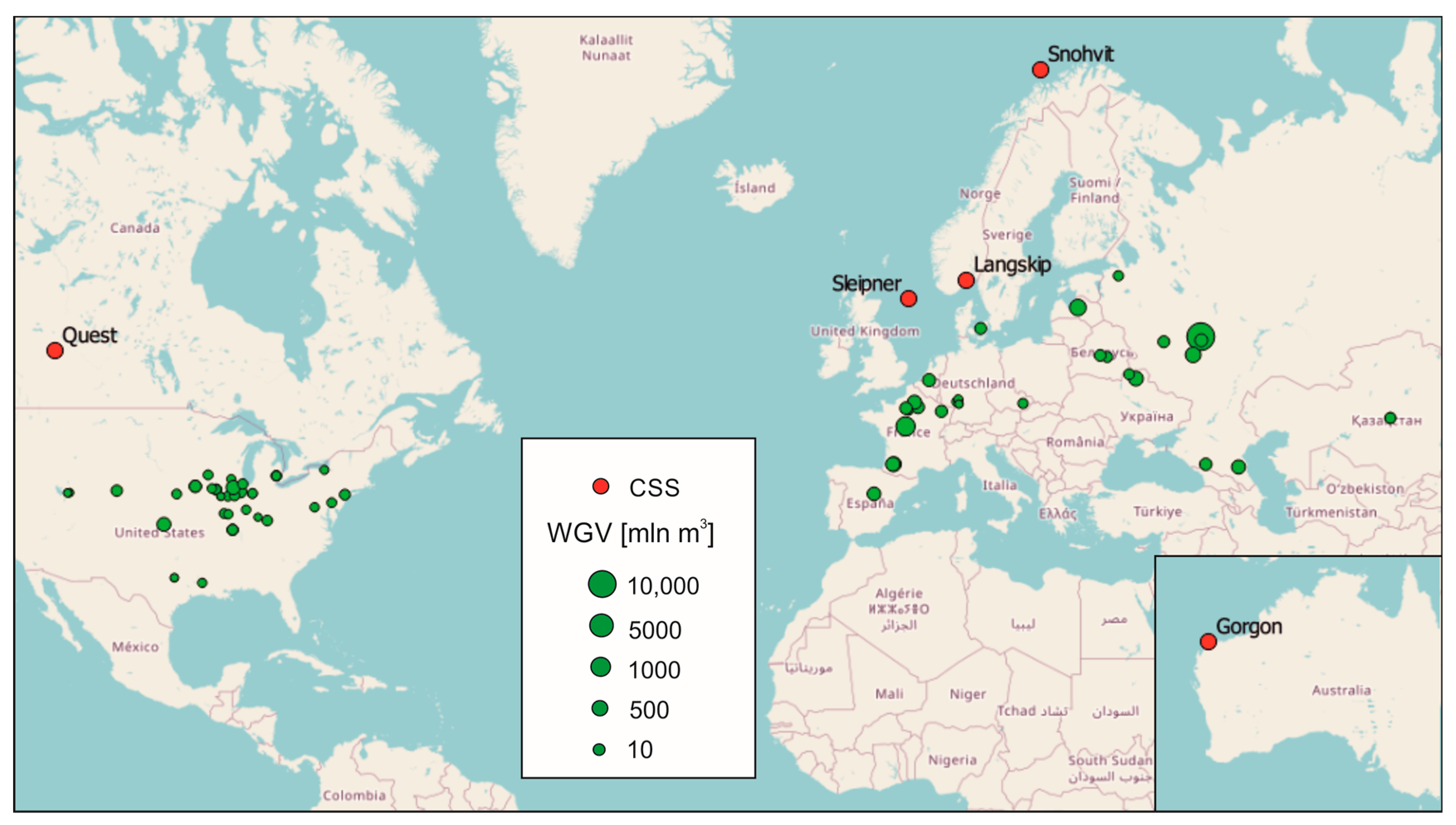
4. Natural Gas, CO2, and Hydrogen Underground Storage Facilities

According to the International Gas Union [165], there are 692 underground natural gas storage facilities in operation around the world. Most of the underground storage facilities are located in depleted natural gas fields (474 in total). A total of 102 UGSs are located in salt caverns. The remaining storage facilities are located in depleted oil fields—41—and rock caverns—3. In the analyzed years 2017–2021, there were 72 commercial underground gas storage projects in aquifers located worldwide (the number of projects per country is given in brackets) in Belarus (3), Belgium (1), Czech Republic (1), Denmark (1), France (10), Germany (3), Kazakhstan (2), Latvia (1), Russia (7), Spain (1), Ukraine (2), and the USA (51) (Figure 2). Working gas volume values for individual storage facilities range from 2 to 10,250 million m3, with an average of 656 million m3. The largest number of storage facilities have capacities of up to 250 million m3 (34), 11 storage facilities have capacities of 250–500 million m3, and 10 storage facilities have capacities of 500 to 750 million m3. A total of 15 storage facilities have capacities between 750 and 2500 million m3, and the remaining (two) have larger capacities. The highest aggregate values of this WGV parameter due to the number of projects were achieved in France with 10,968 million m3, the USA with 12,310 million m3, and Russia with 15,637 million m3. The calculated ratio for individual storage facilities is 62.1%, its minimum value is 32.6%, and its maximum value is 91.5%.
As of 2022, there are 58 demonstration and commercial underground CO2 storage projects in aquifers located worldwide in the US, UK, Australia, Norway, Canada, and Korea. The projects are at various stages of development. A total of 17 projects are in the study phase and 38 are in the construction/implementation phase. Only four CO2 injection projects were operational (Sleipner, Snøhvit, Quest, and Gorgon), and one was in the commissioning phase (Northen Lights) (Figure 3). There were also research and pilot aquifer storage projects around the world (18). Of these, four had a functioning status. These were two projects in Japan and one project each in Spain and Croatia.
The oldest operating CO2 injection project for environmental purposes is the Sleipner project. The Sleipner CO2 storage project is operated by Equinor and is located at the Sleipner Vest field in the Norwegian sector of the North Sea; it is the first industrial-scale CO2 injection project in which CO2 is stored in the brine horizon under the seabed; and injection started in 1996 and continues today. The stored CO2 comes from the purification of natural gas extracted from the Sleipner Vest field. Between 0.8 and 1 million tons of CO2 are injected annually. The Sleipner Vest gas field is the largest condensate gas field in the Sleipner area. Due to the high CO2 content (approximately 9% molar content) that does not allow for gas export, it was necessary to find a way to manage excess CO2 without harming the environment. A plant was built on the Sleipner T platform to purify the gas from CO2, which is then injected and stored at a depth of approximately 800–1000 m. Carbon dioxide storage is carried out in the aquifers of the Utsira Formation. The formation overlies the reservoir rocks containing the gas. The stored formation is composed of homogeneous, unconsolidated fine-grained sandstones with a thickness of 150 to 250 m, porosity of 35–40%, and permeability of 1 to 8 D (Table 2). The formation is covered by an extensive sequence of thick shales, which acts as an effective seal for any vertical CO2 leakage [167,168,169].
Another project launched by Equinor was the Snøhvit project. The Snøhvit CO2 storage project is located in in the central part of the Hammerfest Basin in the Barents Sea. The depth of the water is 330 m. Carbon dioxide is captured from Snøhvit, which is an LNG production facility. Natural gas containing 5–6% CO2 is piped from subsea production facilities to the Melkoya gas processing facility. In the Melkoya facility, CO2 is separated using amine capture. Compressed CO2 in the liquid phase is returned to the Snøhvit field in a 153 km long pipeline. Gas was initially injected into the Tubaen saline formation at 2600 m depth (2008–2011), after pressurization in the water zone of the Sto Formation (Early and Middle Jurassic age) at 2400 m depth (from 2011). The reservoir parameters of the Sto Formation are fairly good. Porosity is above 20% and permeability is about 700 mD. The injection of CO2 started in 2008, with approximately 0.85 million tons of carbon dioxide being injected annually [169,176,177,178].
Equinor’s latest project is Northen Lights, which stores CO2 captured from the industrial plants of Norcem (cement production) and Fortum Oslo Varme (CHP plant waste treatment) on the seabed of the North Sea. The capture capacity of the two facilities is expected to total 800,000 tons. Northern Lights’ maximum planned injection capacity of 1.5 million tons per year allows for additional supplies from third parties. This is an ongoing project. The construction of CO2 transport vessels, onshore CO2 facilities, and storage infrastructure is currently underway and is expected to be completed in 2024, the same year that CO2 injection is scheduled to begin. In the Northern Lights project, carbon dioxide captured from the cement production facility will be transported by ships to the surface installation located in Naturgassparken in the Øygarden municipality, then transported by pipelines to the injection site. CO2 will be stored in the Lower Jurassic complex, where the Johansen and Cook formations are the main storage formations (sandstones) and the Drake formation (shales) provides the main seal [179,180].
Gorgon carbon dioxide injection is being implemented in western Australia. Carbon dioxide is derived from the natural gas treatment at Chevron Australia’s Gorgon liquefied natural gas (LNG) facility. This work began in 2003, with project approvals in 2009. Since then, 17 wells have been drilled, pipelines and compression facilities were constructed and installed, baseline monitoring data were acquired, and injection operation has commenced. The Gorgon CO2 injection system is expected to have a life of 40-plus years. Gas is transported to the injection site via a pipeline located onshore. Then, the carbon dioxide is injected into the Dupuy Formation of the Late Jurassic age. The reservoir has a thickness of 200 to 500 m. The Dupuy Formation consists of massive sandstones and highly bioturbated siltstones. The formation has variable reservoir-quality siltstones with permeabilities below 0.1 mD and sandstones with permeabilities of up to 200 mD. The sealing unit is the basal Barrow Group shale. Since starting gas injection in 2019, more than four million tons of CO2 have been injected into the Dupuy Formation as of January 2021 [181].
The Quest Carbon Capture and Storage Project is located in Alberta, Canada, and is being carried out by Shell. It includes the capture (hydrogen production (tar sands)), pipeline transport, and injection of CO2 into a brine level located onshore. Injection started in 2015 and the injection phase is currently underway. The designed storage capacity is 27 Mt of carbon dioxide, and by 2021, 6.3 million tons of gas have been injected. The injection site is located in the central part of the Western Canada sedimentary basin. CO2 injection is conducted into basal Cambrian sands of Middle Cambrian–Early Devonian age. The thickness of the reservoir rocks ranges from 35 to 47 m. The thickness of the main seal varies very slightly between 21 and 75 m. In addition to the main sealing horizon, the storage complex has two additional seals with thicknesses of 9–41 m and 53–94 m. The average porosity of the storage formation is 16% and its permeability is in the range of 20–1000 mD. The depth of the structure (>2000 m) guarantees suitable conditions for CO2 storage with the temperature at 60 °C and an initial pressure of 20.45 MPa [182,183].
The global experience with underground storage dates back to the 1970s, when the storage of gases in salt caverns began. Underground hydrogen storage is already conducted in salt caverns in Teesside (UK) and Clemens, Splindletop and Moss Bluff (US). However, there are currently no projects for the underground storage of pure hydrogen in aquifers. The only experience is with the storage of hydrogen-containing gas mixtures (town gas) in aquifers (Table 3). The town gas is produced from coal gasification, where oxygen and steam oxidize coal to produce a gaseous mixture of hydrogen (50–60%) with methane (30%), carbon dioxide (20%), and carbon oxide. The objective of the town gas storage was to regulate fluctuations in gas production/demand. In France, at the Beyens project, Gaz de France stored gas containing 50% hydrogen in a saline aquifer with a capacity of 385 million m3 from 1956 to 1972. In Germany, the manufactured gas (62% H2) was stored in an aquifer at 200–250 m in sandstone in the Ketzin reservoir. The Lobodice project was initiated in the Czech Republic when the town gas with 50% H2 and 25% CH4 was stored at 430 m in an aquifer [47,184,185]. During decades of commercial operation, there were no reports of containment failures at these town gas storage sites; however, some changes in the composition of the stored gas are believed to have occurred as a result of biogeochemical reactions within the storage reservoirs [18,186]. In the Beyens project, intense bacterial activity and consequent gas transformation were observed [18].

5. Conclusions

Geological structures in porous rocks serve as potential sites for storing gases like hydrogen, methane, and carbon dioxide underground. Among these, deep saline aquifers and depleted gas reservoirs show promise due to their geological characteristics. These structures occur in sedimentary basins in the form of geological traps. Exploited gas deposits are well explored, and the existing infrastructure allows for their use as underground storage facilities. Deep saline aquifers, although less geologically studied, offer considerable storage potential due to their broad distribution, high permeability, and significant thickness. These are aquifers with highly mineralized water that is not suitable for consumption. Despite weaker geological exploration compared to gas reservoirs, their large storage capacities make them promising candidates for underground storage sites. The most important of the various hydrogen and CO2 trapping mechanisms is, in the short term, structural trapping. In the longer term, other mechanisms may come into use such as dissolution or residue trapping.
The influence of geochemical processes and microbial interactions on the operation of underground gas storage facilities, especially hydrogen, is highlighted. Geochemical reactions taking place in the storage formation can not only change the mineral composition of the rocks but also affect (positively or negatively) the petrophysical parameters of the reservoir rock. Interactions with overburden rocks can result, for example, in the unsealing of the underground storage. Reactions involving microorganisms can result in the loss of or alteration in the composition of stored gas (especially hydrogen).
The selection and characterization of the structure chosen for underground gas storage, the storage capacity, and the safety of the process were identified as the most important aspects related to underground gas storage.
  • The choice of a suitable structure and its detailed characterization determine the success of the whole process of storing gases in aquifers. When selecting the best site for an underground storage facility, various factors must be considered, including geological, technical, economic, environmental, social, political, administrative, and legal aspects. Currently, there is no standardized approach for selecting locations for underground gas storage facilities. Research indicates a wide array of methods utilized globally, demonstrating diverse approaches for evaluating CO2 and hydrogen storage facility locations.
  • The second very important aspect is a reliable estimate of the storage capacity, which determines the feasibility of constructing storage in a given aquifer formation. The assessment of the storage capacity should be based on the geological parameters of the rock formation intended for underground storage; however, it should also take into account the processes occurring during injection, particularly that of pressure build-up.
  • With regard to the safety of the storage and its purpose, the tightness of the underground storage has been identified as the most important feature, determining the success of the entire gas storage process. The degree of tightness of an underground storage facility depends on the type of geological structure and the gas stored.
Utilizing aquifers for the industrial-scale storage of hydrogen and carbon dioxide draws upon the extensive experience of companies engaged in natural gas storage. Tailored approaches are necessary due to the distinct characteristics of carbon dioxide and hydrogen. While storing natural gas in aquifers is common, and CO2 sequestration has been carried out on a large scale for many years, implementing underground hydrogen storage remains unexplored. Key barriers to UHS adoption include geological complexities (recognition of geological structures and their potential geochemical, microbiological, and geomechanical interactions), safety concerns, technical constraints, infrastructural needs, legal considerations, social acceptance, and potential conflicts of interest. Developing cost-effective and safe UHS technology poses a contemporary challenge for governmental bodies, industries, and researchers.
Lessons from underground natural gas storage and carbon dioxide sequestration in aquifers can be applied to underground hydrogen storage. Government agencies, geological services, and energy-intensive industries are interested in storing underground surplus hydrogen from renewable sources. This method allows for the long-term, secure storage of terawatt-hour-scale hydrogen at relatively low costs. However, overcoming various barriers is crucial for the rapid industrial-scale adoption of underground hydrogen storage technology.

Author Contributions

Conceptualization, B.U.-M. and J.M.; methodology, B.U.-M. and J.M.; writing—original draft preparation, B.U.-M. and J.M.; writing—review and editing, B.U.-M. and J.M. All authors have read and agreed to the published version of the manuscript.

Funding

This research was funded by the “Excellent Science” program of the Ministry of Education and Science of Poland, grant No DNK/SP/547981/2022, and the support of the AGH University of Science and Technology research subventions No. 16.16.190.779 and No 16.16.140.315.

Data Availability Statement

No new data were created or analyzed in this study. Data sharing is not applicable to this article.

Conflicts of Interest

The authors declare no conflicts of interest.

References

  1. Uliasz-Misiak, B.; Przybycin, A. Present and future status of the underground space use in Poland. Environ. Earth Sci. 2016, 75, 1430. [Google Scholar] [CrossRef]
  2. Evans, D.; Stephenson, M.; Shaw, R. The present and future use of ‘land’ below ground. Land Use Policy 2009, 26, S302–S316. [Google Scholar] [CrossRef]
  3. UNFCCC. Adoption of the Paris Agreement: Draft Decision; UNFCCC: Bonn, Germany, 2015; pp. 1–32. [Google Scholar]
  4. EU Commission. A Strategy for Competitive, Sustainable and Secure Energy; COM/2010/639; EU Monitor: Brussels, Belgium, 2010; pp. 1–21.
  5. Abe, J.O.; Popoola, A.P.I.; Ajenifuja, E.; Popoola, O.M. Hydrogen energy, economy and storage: Review and recommendation. Int. J. Hydrogen Energy 2019, 44, 15072–15086. [Google Scholar] [CrossRef]
  6. Heinemann, N.; Alcalde, J.; Miocic, J.M.; Hangx, S.J.T.; Kallmeyer, J.; Ostertag-Henning, C.; Hassanpouryouzband, A.; Thaysen, E.M.; Strobel, G.J.; Schmidt-Hattenberger, C.; et al. Enabling large-scale hydrogen storage in porous media—The scientific challenges. Energy Environ. Sci. 2021, 14, 853–864. [Google Scholar] [CrossRef]
  7. Uliasz-Misiak, B.; Misiak, J.; Lewandowska-Śmierzchalska, J. Hydrogen Storage in Porous Rocks: A Bibliometric Analysis of Research Trends. Energies 2024, 17, 805. [Google Scholar] [CrossRef]
  8. Wan, C.; Liu, X.; Wang, J.; Chen, F.; Cheng, D.G. Heterostructuring 2D CO2P nanosheets with 0D CoP via a salt-assisted strategy for boosting hydrogen evolution from ammonia borane hydrolysis. Nano Res. 2023, 16, 6260–6269. [Google Scholar] [CrossRef]
  9. Wan, C.; Li, G.; Wang, J.; Xu, L.; Cheng, D.G.; Chen, F.; Asakura, Y.; Kang, Y.; Yamauchi, Y. Modulating Electronic Metal-Support Interactions to Boost Visible-Light-Driven Hydrolysis of Ammonia Borane: Nickel-Platinum Nanoparticles Supported on Phosphorus-Doped Titania. Angew. Chem. Int. Ed. 2023, 62, e202305371. [Google Scholar] [CrossRef] [PubMed]
  10. Wan, C.; Liang, Y.; Zhou, L.; Huang, J.; Wang, J.; Chen, F.; Zhan, X.; Cheng, D. guo Integration of morphology and electronic structure modulation on cobalt phosphide nanosheets to boost photocatalytic hydrogen evolution from ammonia borane hydrolysis. Green Energy Environ. 2024, 9, 333–343. [Google Scholar] [CrossRef]
  11. Evans, J.P. An Appraisal of Underground Gas Storage Technologies and Incidents, for the Development of Risk Assessment Methodology; Sustainable and Renewable Energy Programme; British Geological Survey: Nottingham, UK, 2007. [Google Scholar]
  12. Kunstman, A.; Poborska-Młynarska, K.; Urbańczyk, K. Construction of storage caverns in salt deposits-geological and mining aspects. Przegląd Geol. 2009, 57, 819–928. (In Polish) [Google Scholar]
  13. Epelle, E.I.; Obande, W.; Udourioh, G.A.; Afolabi, I.C.; Desongu, K.S.; Orivri, U.; Gunes, B.; Okolie, J.A. Perspectives and prospects of underground hydrogen storage and natural hydrogen. Sustain. Energy Fuels 2022, 6, 3324–3343. [Google Scholar] [CrossRef]
  14. Tarkowski, R. Some aspects of underground hydrogen storage. Przegląd Geol. 2017, 65, 282–291. [Google Scholar]
  15. Alms, K.; Ahrens, B.; Graf, M.; Nehler, M. Linking geological and infrastructural requirements for large-scale underground hydrogen storage in Germany. Front. Energy Res. 2023, 11, 1172003. [Google Scholar] [CrossRef]
  16. Matos, C.R.; Carneiro, J.F.; Silva, P.P. Overview of Large-Scale Underground Energy Storage Technologies for Integration of Renewable Energies and Criteria for Reservoir Identification. J. Energy Storage 2019, 21, 241–258. [Google Scholar] [CrossRef]
  17. Caglayan, D.G.; Weber, N.; Heinrichs, H.U.; Linßen, J.; Robinius, M.; Kukla, P.A.; Stolten, D. Technical potential of salt caverns for hydrogen storage in Europe. Int. J. Hydrogen Energy 2020, 45, 6793–6805. [Google Scholar] [CrossRef]
  18. Panfilov, M. Underground and pipeline hydrogen storage. In Compendium of Hydrogen Energy; Elsevier: Amsterdam, The Netherlands, 2016; Volume 2, pp. 91–115. [Google Scholar]
  19. Zivar, D.; Kumar, S.; Foroozesh, J. Underground hydrogen storage: A comprehensive review. Int. J. Hydrogen Energy 2021, 46, 23436–23462. [Google Scholar] [CrossRef]
  20. Aftab, A.; Hassanpouryouzband, A.; Xie, Q.; Machuca, L.L.; Sarmadivaleh, M. Toward a Fundamental Understanding of Geological Hydrogen Storage. Ind. Eng. Chem. Res. 2022, 61, 3233–3253. [Google Scholar] [CrossRef]
  21. Acar, C.; Dincer, I. Review and evaluation of hydrogen production options for better environment. J. Clean. Prod. 2019, 218, 835–849. [Google Scholar] [CrossRef]
  22. Tarkowski, R.; Uliasz-Misiak, B.; Tarkowski, P. Storage of hydrogen, natural gas, and carbon dioxide—Geological and legal conditions. Int. J. Hydrogen Energy 2021, 46, 20010–20022. [Google Scholar] [CrossRef]
  23. Hendriks, C.A.; Blok, K. Underground storage of carbon dioxide. Energy Convers. Manag. 1995, 36, 539–542. [Google Scholar] [CrossRef]
  24. Holt, T.; Jensen, J.I.; Lindeberg, E. Underground storage of CO2 in aquifers and oil reservoirs. Energy Convers. Manag. 1995, 36, 535–538. [Google Scholar] [CrossRef]
  25. Holloway, S. Underground sequestration of carbon dioxide—A viable greenhouse gas mitigation option. Energy 2005, 30, 2318–2333. [Google Scholar] [CrossRef]
  26. Ajayi, T.; Gomes, J.S.; Bera, A. A review of CO2 storage in geological formations emphasizing modeling, monitoring and capacity estimation approaches. Pet. Sci. 2019, 16, 1028–1063. [Google Scholar] [CrossRef]
  27. Bachu, S. CO2 storage in geological media: Role, means, status and barriers to deployment. Prog. Energy Combust. Sci. 2008, 34, 254–273. [Google Scholar] [CrossRef]
  28. Alcalde, J.; Flude, S.; Wilkinson, M.; Johnson, G.; Edlmann, K.; Bond, C.E.; Scott, V.; Gilfillan, S.M.V.; Ogaya, X.; Stuart Haszeldine, R. Estimating geological CO2 storage security to deliver on climate mitigation. Nat. Commun. 2018, 9, 2201. [Google Scholar] [CrossRef] [PubMed]
  29. Aminu, M.D.; Nabavi, S.A.; Rochelle, C.A.; Manovic, V. A review of developments in carbon dioxide storage. Appl. Energy 2017, 208, 1389–1419. [Google Scholar] [CrossRef]
  30. Schultz, R.A.; Heinemann, N.; Horváth, B.; Wickens, J.; Miocic, J.M.; Babarinde, O.O.; Cao, W.; Capuano, P.; Dewers, T.A.; Dusseault, M.; et al. An overview of underground energy-related product storage and sequestration. Geol. Soc. Lond. Spec. Publ. 2023, 528, 15–35. [Google Scholar] [CrossRef]
  31. Metz, B.; Davidson, O.; de Coninck, H.C.; Loos, M.; Meyer, L. IPCC (Intergovernmental Panel on Climate Change). In IPCC Special Report on Carbon Dioxide Capture and Storage; Prepared by Working Group III of the Intergovernmental Panel on Climate Change; Cambridge University Press: New York, NY, USA, 2005. [Google Scholar]
  32. GWPC-IOGCC. Underground Gas Storage Regulatory Considerations: A Guide for State and Federal Regulatory Agencies; Interstate Oil and Gas Compact Commission: Oklahoma City, OK, USA, 2017.
  33. Evans, D.J. A review of underground fuel storage events and putting risk into perspective with other areas of the energy supply chain. Geol. Soc. Spec. Publ. 2009, 313, 173–216. [Google Scholar] [CrossRef]
  34. Al-Shafi, M.; Massarweh, O.; Abushaikha, A.S.; Bicer, Y. A review on underground gas storage systems: Natural gas, hydrogen and carbon sequestration. Energy Rep. 2023, 9, 6251–6266. [Google Scholar] [CrossRef]
  35. Tarkowski, R.; Uliasz-Misiak, B. Use of underground space for the storage of selected gases (CH4, H2, and CO2)—Possible conflicts of interest. Gospod. Surowcami Miner. Resour. Manag. 2021, 37, 141–160. [Google Scholar] [CrossRef]
  36. Chen, Z.; Zhou, F.; Rahman, S.S. Effect of Cap Rock Thickness and Permeability on Geological Storage of CO2: Laboratory Test and Numerical Simulation. Energy Explor. Exploit. 2014, 32, 943–964. [Google Scholar] [CrossRef]
  37. England, W.A.; Mackenzie, A.S.; Mann, D.M.; Quigley, T.M. The movement and entrapment of petroleum fluids in the subsurface. J. Geol. Soc. London. 1987, 144, 327–347. [Google Scholar] [CrossRef]
  38. Shukla, R.; Ranjith, P.; Haque, A.; Choi, X. A review of studies on CO2 sequestration and caprock integrity. Fuel 2010, 89, 2651–2664. [Google Scholar] [CrossRef]
  39. Verga, F. What’s Conventional and What’s Special in a Reservoir Study for Underground Gas Storage. Energies 2018, 11, 1245. [Google Scholar] [CrossRef]
  40. Chadwick, A.; Arts, R.; Bernstone, C.; May, F.; Thibeau, S.; Zweigel, P. Best Practice for the Storage of CO2 in Saline Aquifers. Observations and Guidelines from the SACS and CO2STORE Projects; British Geological Survey Occasional Publication 14; British Geological Survey: Nottingham, UK, 2008. [Google Scholar]
  41. Ismail, I.; Gaganis, V. Carbon Capture, Utilization, and Storage in Saline Aquifers: Subsurface Policies, Development Plans, Well Control Strategies and Optimization Approaches—A Review. Clean Technol. 2023, 5, 609–637. [Google Scholar] [CrossRef]
  42. Nicot, J.P. Evaluation of large-scale CO2 storage on fresh-water sections of aquifers: An example from the Texas Gulf Coast Basin. Int. J. Greenh. Gas Control 2008, 2, 582–593. [Google Scholar] [CrossRef]
  43. Bachu, S.; Adams, J.J. Sequestration of CO2 in geological media in response to climate change: Capacity of deep saline aquifers to sequester CO2 in solution. Energy Convers. Manag. 2003, 44, 3151–3175. [Google Scholar] [CrossRef]
  44. Potdar, R.S.; Vishal, V. Trapping mechanism of CO2 storage in deep saline aquifers: Brief review. In Geologic Carbon Sequestration: Understanding Reservoir Behavior; Springer: Cham, Switzerland, 2016; pp. 47–58. [Google Scholar] [CrossRef]
  45. Zhang, D.; Song, J. Mechanisms for geological carbon sequestration. Procedia IUTAM 2015, 10, 319–327. [Google Scholar] [CrossRef]
  46. Han, W.S.; McPherson, B.J.; Lichtner, P.C.; Wang, F.P. Evaluation of trapping mechanisms in geologic CO2 sequestration: Case study of SACROC northern platform, a 35-year CO2 injection site. Am. J. Sci. 2010, 310, 282–324. [Google Scholar] [CrossRef]
  47. Raza, A.; Arif, M.; Glatz, G.; Mahmoud, M.; Al Kobaisi, M.; Alafnan, S.; Iglauer, S. A holistic overview of underground hydrogen storage: Influencing factors, current understanding, and outlook. Fuel 2022, 330, 125636. [Google Scholar] [CrossRef]
  48. Katz, D.L.; Tek, M.R. Storage of Natural Gas in Saline Aquifers. Water Resour. Res. 1970, 6, 1515–1521. [Google Scholar] [CrossRef]
  49. Ang, L.; Yongming, L.; Xi, C.; Zhongyi, Z.; Yu, P. Review of CO2 sequestration mechanism in saline aquifers. Nat. Gas Ind. B 2022, 9, 383–393. [Google Scholar] [CrossRef]
  50. Iglauer, S. Dissolution Trapping of Carbon Dioxide in Reservoir Formation Brine—A Carbon Storage Mechanism; Nakajima, H., Ed.; IntechOpen: Rijeka, Croatia, 2011; ISBN 978-953-307-636-2. [Google Scholar]
  51. Szulczewski, M.L.; Hesse, M.A.; Juanes, R. Carbon dioxide dissolution in structural and stratigraphic traps. J. Fluid Mech. 2013, 736, 287–315. [Google Scholar] [CrossRef]
  52. Chabab, S.; Théveneau, P.; Coquelet, C.; Corvisier, J.; Paricaud, P. Measurements and predictive models of high-pressure H2 solubility in brine (H2O+NaCl) for underground hydrogen storage application. Int. J. Hydrogen Energy 2020, 45, 32206–32220. [Google Scholar] [CrossRef]
  53. Kimbrel, E.H.; Herring, A.L.; Armstrong, R.T.; Lunati, I.; Bay, B.K.; Wildenschild, D. Experimental characterization of nonwetting phase trapping and implications for geologic CO2 sequestration. Int. J. Greenh. Gas Control 2015, 42, 1–15. [Google Scholar] [CrossRef]
  54. Jafari Raad, S.M.; Leonenko, Y.; Hassanzadeh, H. Hydrogen storage in saline aquifers: Opportunities and challenges. Renew. Sustain. Energy Rev. 2022, 168, 112846. [Google Scholar] [CrossRef]
  55. Hurter, S.; Labregere, D.; Berge, J. Simulations for CO2 Injection Projects With Compositional Simulator. In Proceedings of the SPE Offshore Europe Conference, OnePetro, Aberdeen, UK, 4–7 September 2007; pp. 214–220. [Google Scholar]
  56. Fang, Y.; Baojun, B.; Dazhen, T.; Dunn-Norman, S.; Wronkiewicz, D. Characteristics of CO2 sequestration in saline aquifers. Pet. Sci. 2010, 7, 83–92. [Google Scholar] [CrossRef]
  57. Tong, D.; Trusler, J.P.M.; Vega-Maza, D. Solubility of CO2 in aqueous solutions of CaCl2 or MgCl2 and in a synthetic formation brine at temperatures up to 423 K and pressures up to 40 MPa. J. Chem. Eng. Data 2013, 58, 2116–2124. [Google Scholar] [CrossRef]
  58. Gunter, W.D.; Wiwehar, B.; Perkins, E.H. Aquifer disposal of CO2-rich greenhouse gases: Extension of the time scale of experiment for CO2-sequestering reactions by geochemical modelling. Mineral. Petrol. 1997, 59, 121–140. [Google Scholar] [CrossRef]
  59. De Silva, G.P.D.; Ranjith, P.G.; Perera, M.S.A. Geochemical aspects of CO2 sequestration in deep saline aquifers: A review. Fuel 2015, 155, 128–143. [Google Scholar] [CrossRef]
  60. Rimmelé, G.; Barlet-Gouédard, V.; Renard, F. Evolution of the Petrophysical and Mineralogical Properties of Two Reservoir Rocks Under Thermodynamic Conditions Relevant for CO2 Geological Storage at 3 km Depth. Oil Gas Sci. Technol. Rev. L’institut Français Pétrole 2010, 65, 565–580. [Google Scholar] [CrossRef]
  61. Shiraki, R.; Dunn, T.L. Experimental study on water–rock interactions during CO2 flooding in the Tensleep Formation, Wyoming, USA. Appl. Geochem. 2000, 15, 265–279. [Google Scholar] [CrossRef]
  62. Bachu, S.; Gunter, W.D.; Perkins, E.H. Aquifer disposal of CO2: Hydrodynamic and mineral trapping. Energy Convers. Manag. 1994, 35, 269–279. [Google Scholar] [CrossRef]
  63. Thiyagarajan, S.R.; Emadi, H.; Hussain, A.; Patange, P.; Watson, M. A comprehensive review of the mechanisms and efficiency of underground hydrogen storage. J. Energy Storage 2022, 51, 104490. [Google Scholar] [CrossRef]
  64. Saeed, M.; Jadhawar, P.; Bagala, S. Geochemical Effects on Storage Gases and Reservoir Rock during Underground Hydrogen Storage: A Depleted North Sea Oil Reservoir Case Study. Hydrogen 2023, 4, 323–337. [Google Scholar] [CrossRef]
  65. Yekta, A.E.; Pichavant, M.; Audigane, P. Evaluation of geochemical reactivity of hydrogen in sandstone: Application to geological storage. Appl. Geochem. 2018, 95, 182–194. [Google Scholar] [CrossRef]
  66. Hemme, C.; van Berk, W. Potential risk of H2S generation and release in salt cavern gas storage. J. Nat. Gas Sci. Eng. 2017, 47, 114–123. [Google Scholar] [CrossRef]
  67. Pijnenburg, R.P.J.; Verberne, B.A.; Hangx, S.J.T.; Spiers, C.J. Inelastic Deformation of the Slochteren Sandstone: Stress-Strain Relations and Implications for Induced Seismicity in the Groningen Gas Field. J. Geophys. Res. Solid Earth 2019, 124, 5254–5282. [Google Scholar] [CrossRef]
  68. Peng, D.D.; Fowler, M.; Elkamel, A.; Almansoori, A.; Walker, S.B. Enabling utility-scale electrical energy storage by a power-to-gas energy hub and underground storage of hydrogen and natural gas. J. Nat. Gas Sci. Eng. 2016, 35, 1180–1199. [Google Scholar] [CrossRef]
  69. Hagemann, B.; Rasoulzadeh, M.; Panfilov, M.; Ganzer, L.; Reitenbach, V. Hydrogenization of underground storage of natural gas: Impact of hydrogen on the hydrodynamic and biochemical behavior. Comput. Geosci. 2016, 20, 595–606. [Google Scholar] [CrossRef]
  70. Gregory, S.P.; Barnett, M.J.; Field, L.P.; Milodowski, A.E. Subsurface Microbial Hydrogen Cycling: Natural Occurrence and Implications for Industry. Microorganisms 2019, 7, 53. [Google Scholar] [CrossRef]
  71. Bernardez, L.A.; De Lima, L.R.P.A.; De Jesus, E.B.; Ramos, C.L.S.; Almeida, P.F. A kinetic study on bacterial sulfate reduction. Bioprocess Biosyst. Eng. 2013, 36, 1861–1869. [Google Scholar] [CrossRef]
  72. Jørgensen, B.B.; Isaksen, M.F.; Jannasch, H.W. Bacterial Sulfate Reduction Above 100C in Deep-Sea Hydrothermal Vent Sediments. Science 1992, 258, 1756–1757. [Google Scholar] [CrossRef]
  73. Machel, H.G. Bacterial and thermochemical sulfate reduction in diagenetic settings—Old and new insights. Sediment. Geol. 2001, 140, 143–175. [Google Scholar] [CrossRef]
  74. Thaysen, E.M.; McMahon, S.; Strobel, G.J.; Butler, I.B.; Ngwenya, B.T.; Heinemann, N.; Wilkinson, M.; Hassanpouryouzband, A.; McDermott, C.I.; Edlmann, K. Estimating microbial growth and hydrogen consumption in hydrogen storage in porous media. Renew. Sustain. Energy Rev. 2021, 151, 111481. [Google Scholar] [CrossRef]
  75. Ramesh Kumar, K.; Honorio, H.; Chandra, D.; Lesueur, M.; Hajibeygi, H. Comprehensive review of geomechanics of underground hydrogen storage in depleted reservoirs and salt caverns. J. Energy Storage 2023, 73, 108912. [Google Scholar] [CrossRef]
  76. Miocic, J.M.; Heinemann, N.; Alcalde, J.; Edlmann, K.; Schultz, R.A. Enabling Secure Subsurface Storage in Future Energy Systems; Geological Society of London Special Publication; Geological Society of London: London, UK, 2023; Volume 528, pp. 1–7. [Google Scholar] [CrossRef]
  77. DOE/NETL. BEST PRACTICES: Monitoring, Verification, and Accounting (MVA) for Geologic Storage Projects DOE/NETL; NETL: Albany, NY, USA, 2017.
  78. Katz, D.L.; Coats, K.H. Underground Storage of Fluids; Ulrich’s Books Inc.: Ann Arbor, MI, USA, 1968. [Google Scholar]
  79. Katz, D.L.; Tek, M.R. Overview on Underground Storage of Natural Gas. J. Pet. Technol. 1981, 33, 943–951. [Google Scholar] [CrossRef]
  80. Foster Associates Inc. Profile of Underground Natural Gas Storage Facilities and Market Hubs; Foster Associates Inc.: Washington, DC, USA, 1995. [Google Scholar]
  81. Behrouz, T.; Askari, A.; Forghaani, S.; Basirat, R.M.; Teymouri, A.; Bonyad, H. Fast Screening Method to Prioritize Underground Gas Storage Structures for Site Selection. In Proceedings of the International Gas Union Research Conference (IGRC 2014), Copenhagen, Denmark, 17–19 September 2014; Volume 3, pp. 2378–2386. [Google Scholar]
  82. Çetin Demirel, N.; Demirel, T.; Deveci, M.; Vardar, G. Location selection for underground natural gas storage using Choquet integral. J. Nat. Gas Sci. Eng. 2017, 45, 368–379. [Google Scholar] [CrossRef]
  83. Yousefi-Sahzabi, A.; Sasaki, K.; Djamaluddin, I.; Yousefi, H.; Sugai, Y. GIS modeling of CO2 emission sources and storage possibilities. Energy Procedia 2011, 4, 2831–2838. [Google Scholar] [CrossRef]
  84. Le Gallo, Y.; Lecomte, A. Global Industrial CCS Technology Roadmap—Sectoral Assessment: Source-Tosink Matching Final Report; UNIDO: Vienna, Austria, 2011. [Google Scholar]
  85. Bradshaw, J.; Dance, T. Mapping geological storage prospectivity of CO2 for the world’s sedimentary basins and regional source to sink matching. In Proceedings of the Greenhouse Gas Control Technologies; Elsevier Science Ltd.: Vancouver, BC, Canada, 2005; pp. 583–591. [Google Scholar]
  86. Delprat-Jannaud, F.; Korre, A.; Shi, J.Q.; McConnell, B.; Arvanitis, A.; Boavida, D.; Car, M.; Gastine, M.; Grunnaleite, I.; Bateman, K.; et al. State-of-the-Art of Review CO2 Storage Site Selection and Characterisation Methods; IFP Energies nouvelles: Solaize, France, 2013. [Google Scholar]
  87. DNV. CO2QUALSTORE Guideline for Selection and Qualification of Sites and Projects for Geological Storage of CO2; DNV: Hong Kong, China, 2010. [Google Scholar]
  88. Raza, A.; Rezaee, R.; Gholami, R.; Bing, C.H.; Nagarajan, R.; Hamid, M.A. A screening criterion for selection of suitable CO2 storage sites. J. Nat. Gas Sci. Eng. 2016, 28, 317–327. [Google Scholar] [CrossRef]
  89. Uliasz-Misiak, B. CO2 storage capacity classification and site selection criteria. Gospod. Surowcami Miner. Resour. Manag. 2009, 25, 97–108. [Google Scholar]
  90. Vangkilde-Pedersen, T.; Anthonsen, K.L.; Smith, N.; Kirk, K.; Neele, F.; van der Meer, B.; Le Gallo, Y.; Bossie-Codreanu, D.; Wojcicki, A.; Le Nindre, Y.M.; et al. Assessing European capacity for geological storage of carbon dioxide-the EU GeoCapacity project. Energy Procedia 2009, 1, 2663–2670. [Google Scholar] [CrossRef]
  91. Tarkowski, R.; Marek, S.; Uliasz-Misiak, B. Preliminary geological analysis of structures to store CO2 within the Belchatow area. Gospod. Surowcami Miner. 2009, 25, 37–45. (In Polish) [Google Scholar]
  92. Kaldi, J.G.; Gibson-Poole, C.M. Storage Capacity Estimation, Site Selection and Characterisation for CO2 Storage Projects; Cooperative Research Centre for Greenhouse Gas Technologies: Canberra, Australia, 2008. [Google Scholar]
  93. IEA GHG. CCS Site Characterisation Criteria; IEA Greenhouse Gas R&D Programme: Cheltenham, UK, 2009. [Google Scholar]
  94. Alcalde, J.; Heinemann, N.; James, A.; Bond, C.E.; Ghanbari, S.; Mackay, E.J.; Haszeldine, R.S.; Faulkner, D.R.; Worden, R.H.; Allen, M.J. A criteria-driven approach to the CO2 storage site selection of East Mey for the acorn project in the North Sea. Mar. Pet. Geol. 2021, 133, 105309. [Google Scholar] [CrossRef]
  95. CSA Z741-2012 (R2017); Geological Storage of Carbon Dioxide. Geological Society: London, UK, 2017; pp. 1–80.
  96. Llamas, B.; Cámara, A. Application of multicriteria algorithm to select suitable areas for storing CO2: CO2SiteAssess software. Energy Procedia 2014, 63, 4977–4986. [Google Scholar] [CrossRef]
  97. Llamas, B.; Cienfuegos, P. Multicriteria Decision Methodology to Select Suitable Areas for Storing CO2. Energy Environ. 2012, 23, 249–264. [Google Scholar] [CrossRef]
  98. Hsu, C.-W.; Chen, L.T.; Hu, A.H.; Chang, Y.M. Site selection for carbon dioxide geological storage using analytic network process. Sep. Purif. Technol. 2012, 94, 146–153. [Google Scholar] [CrossRef]
  99. Deveci, M.; Demirel, N.Ç.; John, R.; Özcan, E. Fuzzy multi-criteria decision making for carbon dioxide geological storage in Turkey. J. Nat. Gas Sci. Eng. 2015, 27, 692–705. [Google Scholar] [CrossRef]
  100. Firtina Ertiş, İ. Appliaction of multi-criteria decision making for geological carbon dioxide storage area in Turkey. Anadolu Univ. J. Sci. Technol. A Appl. Sci. Eng. Year 2018, 19, 536–545. [Google Scholar] [CrossRef]
  101. Nemati, B.; Mapar, M.; Davarazar, P.; Zandi, S.; Davarazar, M.; Jahanianfard, D.; Mohammadi, M. A sustainable approach for site selection of underground hydrogen storage facilities using fuzzy-delphi methodology. J. Settl. Spat. Plan. 2020, 2020, 5–16. [Google Scholar] [CrossRef]
  102. Lewandowska-Śmierzchalska, J.; Tarkowski, R.; Uliasz-Misiak, B. Screening and ranking framework for underground hydrogen storage site selection in Poland. Int. J. Hydrogen Energy 2018, 43, 4401–4414. [Google Scholar] [CrossRef]
  103. Bouteldja, M.; Acosta, T.; Carlier, B.; Reveillere, A.; Jannel, H.; Fournier, C. Definition of Selection Criteria for a Hydrogen Storage Site in Depleted Fields or Aquifers, Hystories Project: Rueil-Malmaison, France, 2021.
  104. Kruck, O.; Crotogino, F. Benchmarking of Selected Storage Options—“HyUnder” Project; European Commission: Brussels, Belgium, 2013.
  105. Guo, W.; Zhang, B.; Liang, Y.; Qiu, R.; Wei, X.; Niu, P.; Zhang, H.; Li, Z. Improved method and practice for site selection of underground gas storage under complex geological conditions. J. Nat. Gas Sci. Eng. 2022, 108, 104813. [Google Scholar] [CrossRef]
  106. Bachu, S.; Bonijoly, D.; Bradshaw, J.; Burruss, R.; Holloway, S.; Christensen, N.P.; Mathiassen, O.M. CO2 storage capacity estimation: Methodology and gaps. Int. J. Greenh. Gas Control 2007, 1, 430–443. [Google Scholar] [CrossRef]
  107. Gorecki, C.D.; Ayash, S.C.; Liu, G.; Braunberger, J.R.; Dotzenrod, N.W. A comparison of volumetric and dynamic CO2 storage resource and efficiency in deep saline formations. Int. J. Greenh. Gas Control 2015, 42, 213–225. [Google Scholar] [CrossRef]
  108. Sopher, D.; Juhlin, C.; Erlström, M. A probabilistic assessment of the effective CO2 storage capacity within the Swedish sector of the Baltic Basin. Int. J. Greenh. Gas Control 2014, 30, 148–170. [Google Scholar] [CrossRef]
  109. Uliasz-Misiak, B. Regional-scale CO2 storage capacity estimation in Mesozoic aquifers of Poland. Oil Gas Sci. Technol. 2011, 66, 37–45. [Google Scholar] [CrossRef]
  110. Bradshaw, J.; Allinson, G.; Bradshaw, B.E.; Nguyen, V.; Rigg, A.J.; Spencer, L.; Wilson, P. Australia’s CO2 geological storage potential and matching of emission sources to potential sinks. Energy 2004, 29, 1623–1631. [Google Scholar] [CrossRef]
  111. Brennan, S.T.; Burruss, R.C.; Merrill, M.D.; Freeman, P.A.; Ruppert, L.F.; Mcnutt, M.K. A Probabilistic Assessment Methodology for the Evaluation of Geologic Carbon Dioxide Storage; US Geological Survey: Reston, VA, USA, 2010. [Google Scholar]
  112. Popova, O.H.; Small, M.J.; McCoy, S.T.; Thomas, A.C.; Karimi, B.; Goodman, A.; Carter, K.M. Comparative analysis of carbon dioxide storage resource assessment methodologies. Environ. Geosci. 2012, 19, 105–124. [Google Scholar] [CrossRef]
  113. Kopp, A.; Class, H.; Helmig, R. Investigations on CO2 storage capacity in saline aquifers—Part 2: Estimation of storage capacity coefficients. Int. J. Greenh. Gas Control 2009, 3, 277–287. [Google Scholar] [CrossRef]
  114. Calvo, R.; Gvirtzman, Z. CO2 Storage Capacity Assessment in the Deep Saline Aquifers of Southern Israel. Energy Procedia 2013, 37, 5118–5123. [Google Scholar] [CrossRef]
  115. Cavanagh, A.; Wildgust, N. Pressurization and brine displacement issues for deep saline formation CO2 storage. Energy Procedia 2011, 4, 4814–4821. [Google Scholar] [CrossRef]
  116. Van der Meer, L.G.H.B.; Yavuz, F. CO2 storage capacity calculations for the Dutch subsurface. Energy Procedia 2009, 1, 2615–2622. [Google Scholar] [CrossRef]
  117. Bachu, S. Review of CO2 storage efficiency in deep saline aquifers. Int. J. Greenh. Gas Control 2015, 40, 188–202. [Google Scholar] [CrossRef]
  118. Luboń, K. CO2 storage capacity of a deep aquifer depending on the injection well location and cap rock capillary pressure. Gospod. Surowcami Miner. 2020, 36, 173–196. [Google Scholar]
  119. Zhang, Z.; Agarwal, R.K.; Zhang, Z.; Agarwal, R.K. Numerical simulation and optimization of CO2 sequestration in saline aquifers for vertical and horizontal well injection. Comput. Geosci. 2012, 16, 891–899. [Google Scholar] [CrossRef]
  120. Akai, T.; Kuriyama, T.; Kato, S.; Okabe, H. Numerical modelling of long-term CO2 storage mechanisms in saline aquifers using the Sleipner benchmark dataset. Int. J. Greenh. Gas Control 2021, 110, 103405. [Google Scholar] [CrossRef]
  121. Wang, Y.; Xu, Y.; Zhang, K. Investigation of CO2 storage capacity in open saline aquifers with numerical models. Procedia Eng. 2012, 31, 886–892. [Google Scholar] [CrossRef]
  122. Zhou, Q.; Birkholzer, J.T.; Tsang, C.F.; Rutqvist, J. A method for quick assessment of CO2 storage capacity in closed and semi-closed saline formations. Int. J. Greenh. Gas Control 2008, 2, 626–639. [Google Scholar] [CrossRef]
  123. Ehlig-Economides, C.; Economides, M.J. Sequestering carbon dioxide in a closed underground volume. J. Pet. Sci. Eng. 2010, 70, 123–130. [Google Scholar] [CrossRef]
  124. Cavanagh, A.J.; Yousefi, S.H.; Wilkinson, M.; Groenenberg, R.M. Hydrogen Storage Potential of Existing European Gas Storage Sites in Depleted Gas Fields and Aquifers; European Commission: Brussels, Belgium, 2022.
  125. Luboń, K.T.; Tarkowski, R. Numerical simulation of hydrogen storage in the Konary deep saline aquifer trap. Gospod. Surowcami Miner. Miner. Resour. Manag. 2023, 39, 103–124. [Google Scholar] [CrossRef]
  126. Bouteldja, M.; Gallo, Y. Le From hydrogen storage potential to hydrogen capacities in underground hydrogen storages. In Proceedings of the 84th EAGE Annual Conference & Exhibition, Vienna, Austria, 5–8 June 2023; Volume 2023, pp. 1–5. [Google Scholar] [CrossRef]
  127. Wallace, R.L.; Cai, Z.; Zhang, H.; Zhang, K.; Guo, C. Utility-scale subsurface hydrogen storage: UK perspectives and technology. Int. J. Hydrogen Energy 2021, 46, 25137–25159. [Google Scholar] [CrossRef]
  128. Scafidi, J.; Wilkinson, M.; Gilfillan, S.M.V.; Heinemann, N.; Haszeldine, R.S. A quantitative assessment of the hydrogen storage capacity of the UK continental shelf. Int. J. Hydrogen Energy 2021, 46, 8629–8639. [Google Scholar] [CrossRef]
  129. Heinemann, N.; Scafidi, J.; Pickup, G.; Thaysen, E.M.; Hassanpouryouzband, A.; Wilkinson, M.; Satterley, A.K.; Booth, M.G.; Edlmann, K.; Haszeldine, R.S. Hydrogen storage in saline aquifers: The role of cushion gas for injection and production. Int. J. Hydrogen Energy 2021, 46, 39284–39296. [Google Scholar] [CrossRef]
  130. Zhao, Q.; Wang, Y.; Chen, C. Numerical simulation of the impact of different cushion gases on underground hydrogen storage in aquifers based on an experimentally-benchmarked equation-of-state. Int. J. Hydrogen Energy 2024, 50, 495–511. [Google Scholar] [CrossRef]
  131. Lord, A.S.; Kobos, P.H.; Borns, D.J. Geologic storage of hydrogen: Scaling up to meet city transportation demands. Int. J. Hydrogen Energy 2014, 39, 15570–15582. [Google Scholar] [CrossRef]
  132. Luboń, K.; Tarkowski, R. Numerical simulation of hydrogen injection and withdrawal to and from a deep aquifer in NW Poland. Int. J. Hydrogen Energy 2020, 45, 2068–2083. [Google Scholar] [CrossRef]
  133. Chai, M.; Chen, Z.; Nourozieh, H.; Yang, M. Numerical simulation of large-scale seasonal hydrogen storage in an anticline aquifer: A case study capturing hydrogen interactions and cushion gas injection. Appl. Energy 2023, 334, 120655. [Google Scholar] [CrossRef]
  134. Rütters, H.; Möller, I.; May, F.; Flornes, K.; Hladik, V.; Arvanitis, A.; Gülec, N.; Bakiler, C.; Dudu, A.; Kucharic, L.; et al. State-of-the-Art of Monitoring Methods to Evaluate CO2 Storage Site Performance. CGS Europe Key Report 2013, 1, 109. [Google Scholar] [CrossRef]
  135. Zhang, Y.; Jackson, C.; Zahasky, C.; Nadhira, A.; Krevor, S. European carbon storage resource requirements of climate change mitigation targets. Int. J. Greenh. Gas Control 2022, 114, 103568. [Google Scholar] [CrossRef]
  136. Celia, M.A.; Bachu, S.; Nordbotten, J.M.; Bandilla, K.W. Status of CO2 storage in deep saline aquifers with emphasis on modeling approaches and practical simulations. Water Resour. Res. 2015, 51, 6846–6892. [Google Scholar] [CrossRef]
  137. Qin, J.; Zhong, Q.; Tang, Y.; Rui, Z.; Qiu, S.; Chen, H. CO2 storage potential assessment of offshore saline aquifers in China. Fuel 2023, 341, 127681. [Google Scholar] [CrossRef]
  138. Uliasz-Misiak, B.; Lewandowska-Smierzchalska, J.; Matuła, R. Hydrogen Storage Potential in Natural Gas Deposits in the Polish Lowlands. Energies 2024, 17, 374. [Google Scholar] [CrossRef]
  139. Le Gallo, Y.; Bouteldja, M. 3D Multi-Realization Simulations for Fluid Flow and Mixing Issues at European Scale; Geological Society: London, UK, 2023. [Google Scholar]
  140. Vavra, C.L.; Kaldi, J.G.; Sneider, R.M. Geological applications of capillary pressure: A review. Am. Assoc. Pet. Geol. Bull. 1992, 76, 840–850. [Google Scholar] [CrossRef]
  141. Veil, J.A.; Puder, M.G.; Elcock, D.; Redweik, J.R.J. A White Paper Describing Produced Water from Production of Crude Oil, Natural Gas, and Coal Bed Methane; Argonne National Laboratory: Lemont, IL, USA, 2004. [Google Scholar]
  142. Wei, L.; Jie, C.; Deyi, J.; Xilin, S.; Yinping, L.; Daemen, J.J.K.; Chunhe, Y. Tightness and suitability evaluation of abandoned salt caverns served as hydrocarbon energies storage under adverse geological conditions (AGC). Appl. Energy 2016, 178, 703–720. [Google Scholar] [CrossRef]
  143. Vilarrasa, V.; Makhnenko, R.; Gheibi, S. Geomechanical analysis of the influence of CO 2 injection location on fault stability. J. Rock Mech. Geotech. Eng. 2016, 8, 805–818. [Google Scholar] [CrossRef]
  144. Song, Y.; Jun, S.; Na, Y.; Kim, K.; Jang, Y.; Wang, J. Geomechanical challenges during geological CO2 storage: A review. Chem. Eng. J. 2023, 456, 140968. [Google Scholar] [CrossRef]
  145. Rutqvist, J. The Geomechanics of CO2 Storage in Deep Sedimentary Formations. Geotech. Geol. Eng. 2012, 30, 525–551. [Google Scholar] [CrossRef]
  146. Dautriat, J.; Gland, N.; Guelard, J.; Dimanov, A.; Raphanel, J.L. Axial and Radial Permeability Evolutions of Compressed Sandstones: End Effects and Shear-band Induced Permeability Anisotropy. Pure Appl. Geophys. 2009, 166, 1037–1061. [Google Scholar] [CrossRef]
  147. Ostermeier, R.M. Deepwater Gulf of Mexico Turbidites—Compaction Effects on Porosity and Permeability. SPE Form. Eval. 1995, 10, 79–85. [Google Scholar] [CrossRef]
  148. Suckale, J. Moderate-to-large seismicity induced by hydrocarbon production. Lead. Edge 2010, 29, 310–319. [Google Scholar] [CrossRef]
  149. Hangx, S.; Bakker, E.; Bertier, P.; Nover, G.; Busch, A. Chemical–mechanical coupling observed for depleted oil reservoirs subjected to long-term CO2-exposure—A case study of the Werkendam natural CO2 analogue field. Earth Planet. Sci. Lett. 2015, 428, 230–242. [Google Scholar] [CrossRef]
  150. Song, J.; Zhang, D. Comprehensive Review of Caprock-Sealing Mechanisms for Geologic Carbon Sequestration. Environ. Sci. Technol. 2012, 47, 9–22. [Google Scholar] [CrossRef] [PubMed]
  151. Dewhurst, D.N.; Piane, C.D.; Esteban, L.; Sarout, J.; Josh, M.; Pervukhina, M.; Clennell, M. Ben Microstructural, Geomechanical, and Petrophysical Characterization of Shale Caprocks. Geophys. Monogr. Ser. 2018, 238, 1–30. [Google Scholar] [CrossRef]
  152. Van Noort, R. Effects of clay swelling or shrinkage on shale caprock integrity. In Proceedings of the 80th EAGE Conference and Exhibition, Copenhagen, Denmark, 11–14 June 2018; Volume 2018, pp. 1–5. [Google Scholar] [CrossRef]
  153. Zeng, L.; Vialle, S.; Ennis-King, J.; Esteban, L.; Sarmadivaleh, M.; Sarout, J.; Dautriat, J.; Giwelli, A.; Xie, Q. Role of geochemical reactions on caprock integrity during underground hydrogen storage. J. Energy Storage 2023, 65, 107414. [Google Scholar] [CrossRef]
  154. Spiers, C.J.; Hangx, S.J.T.; Niemeijer, A.R. New approaches in experimental research on rock and fault behaviour in the Groningen gas field. Geol. Mijnb./Neth. J. Geosci. 2017, 96, s55–s69. [Google Scholar] [CrossRef]
  155. Ugarte, E.R.; Salehi, S. A Review on Well Integrity Issues for Underground Hydrogen Storage. J. Energy Resour. Technol. Trans. ASME 2022, 144, 042001. [Google Scholar] [CrossRef]
  156. IEA GHG. Long Term Integrity of CO2 Storage-Well Abandonment; Technical Study; IEA GHG: Cheltenham, UK, 2009. [Google Scholar]
  157. Wu, L.; Yi, L.; Taoutaou, S.; Yao, K.; Fan, Y.; Liu, W.; Fan, X.; Liu, H.; Liu, L. Maintaining Well Integrity in Underground Gas Storage Wells in China Using a Novel Cementing Technology. In Proceedings of the Abu Dhabi International Petroleum Exhibition and Conference, Abu Dhabi, United Arab Emirates, 10–13 November 2014; Volume 4, pp. 2794–2803. [Google Scholar] [CrossRef]
  158. Li, B.; Zhou, F.; Li, H.; Duguid, A.; Que, L.; Xue, Y.; Tan, Y. Prediction of CO2 leakage risk for wells in carbon sequestration fields with an optimal artificial neural network. Int. J. Greenh. Gas Control 2018, 68, 276–286. [Google Scholar] [CrossRef]
  159. Aftab, A.; Hassanpouryouzband, A.; Martin, A.; Kendrick, J.E.; Thaysen, E.M.; Heinemann, N.; Utley, J.; Wilkinson, M.; Haszeldine, R.S.; Edlmann, K. Geochemical Integrity of Wellbore Cements during Geological Hydrogen Storage. Environ. Sci. Technol. Lett. 2023, 10, 551–556. [Google Scholar] [CrossRef]
  160. Iorio, V.S.; Cracolici, F.; Parrozza, F.; Sabatino, L.M.F.; Massara, E.P.; Consonni, A.; Tritto, C.; De Simoni, M. Cement to Safeguard the Wells Integrity in Underground Hydrogen Storage: An Experimental Investigation. Chem. Eng. Trans. 2022, 96, 307–312. [Google Scholar] [CrossRef]
  161. Bois, A.P.; Vu, M.H.; Ghabezloo, S.; Sulem, J.; Garnier, A.; Laudet, J.B.Î. Cement Sheath Integrity for CO2 Storage—An Integrated Perspective. Energy Procedia 2013, 37, 5628–5641. [Google Scholar] [CrossRef]
  162. Bai, M.; Zhang, Z.; Fu, X. A review on well integrity issues for CO2 geological storage and enhanced gas recovery. Renew. Sustain. Energy Rev. 2016, 59, 920–926. [Google Scholar] [CrossRef]
  163. Kanezaki, T.; Narazaki, C.; Mine, Y.; Matsuoka, S.; Murakami, Y. Effects of hydrogen on fatigue crack growth behavior of austenitic stainless steels. Int. J. Hydrogen Energy 2008, 33, 2604–2619. [Google Scholar] [CrossRef]
  164. Reitenbach, V.; Ganzer, L.; Albrecht, D.; Hagemann, B. Influence of added hydrogen on underground gas storage: A review of key issues. Environ. Earth Sci. 2015, 73, 6927–6937. [Google Scholar] [CrossRef]
  165. UGS Storage Committee—Underground Gas Storage Database. Available online: http://ugs.igu.org/index.php/ugs_list/get_list (accessed on 18 December 2023).
  166. OpenStreetMap. Available online: https://www.openstreetmap.org/about (accessed on 19 December 2023).
  167. Equinor The Sleipner Area—Equinor. Available online: https://www.equinor.com/energy/sleipner (accessed on 16 December 2023).
  168. Chadwick, R.A.; Zweigel, P.; Gregersen, U.; Kirby, G.A.; Holloway, S.; Johannessen, P.N. Geological reservoir characterization of a CO2 storage site: The Utsira Sand, Sleipner, northern North Sea. Energy 2004, 29, 1371–1381. [Google Scholar] [CrossRef]
  169. Eiken, O.; Ringrose, P.; Hermanrud, C.; Nazarian, B.; Torp, T.A.; Høier, L. Lessons learned from 14 years of CCS operations: Sleipner, In Salah and Snøhvit. Energy Procedia 2011, 4, 5541–5548. [Google Scholar] [CrossRef]
  170. Chadwick, R.A.; Eiken, O. Offshore CO2 storage: Sleipner natural gas field beneath the North Sea. In Geological Storage of Carbon Dioxide (CO2): Geoscience, Technologies, Environmental Aspects and Legal Frameworks; Gluyas, J., Mathias, S., Eds.; Woodhead Publishing: Cambridge, UK, 2013; pp. 227–250. ISBN 9780857094278. [Google Scholar]
  171. Harvey, S.; Hopkins, J.; Kuehl, H.; O’Brien, S.; Mateeva, A. Quest CCS Facility: Microseismic System Monitoring. In Proceedings of the 15th International Conference on Greenhouse Gas Control Technologies, Abu Dhabi, United Arab Emirates, 15–18 March 2021; pp. 1–16. [Google Scholar]
  172. Michael, K.; Golab, A.; Shulakova, V.; Ennis-King, J.; Allinson, G.; Sharma, S.; Aiken, T. Geological storage of CO2 in saline aquifers—A review of the experience from existing storage operations. Int. J. Greenh. Gas Control 2010, 4, 659–667. [Google Scholar] [CrossRef]
  173. Government of Alberta. Quest Carbon Capture and Storage Project 2014; Government of Alberta: Edmonton, AB, Canada, 2014.
  174. Government of Alberta. Quest Carbon Capture and Storage Project: Annual Report, 2021—Open Government; Government of Alberta: Edmonton, AB, Canada, 2022.
  175. Tremosa, J.; Castillo, C.; Quang Vong, C.; Kervévan, C.; Lassin, A.; Audigane, P.; Trémosa, J. Long-term assessment of geochemical reactivity of CO2 storage in highly saline aquifers: Application to Ketzin, In Salah and Snøhvit storage sites. Int. J. Greenh. Gas Control 2014, 20, 2–26. [Google Scholar] [CrossRef]
  176. Equinor The Snøhvit Future Project—Equinor. Available online: https://www.equinor.com/energy/snohvit-future (accessed on 16 December 2023).
  177. Estublier, A.; Lackner, A.S. Long-term simulation of the Snøhvit CO2 storage. Energy Procedia 2009, 1, 3221–3228. [Google Scholar] [CrossRef]
  178. Hansen, O.; Gilding, D.; Nazarian, B.; Osdal, B.; Ringrose, P.; Kristoffersen, J.B.; Eiken, O.; Hansen, H. Snøhvit: The History of Injecting and Storing 1 Mt CO2 in the Fluvial Tubåen Fm. Energy Procedia 2013, 37, 3565–3573. [Google Scholar] [CrossRef]
  179. Equinor. Northen Ligths Project Concept Report; FEED Report; Equinor: Stavanger, Norway, 2020. [Google Scholar]
  180. Equinor The Northern Lights Project—Equinor. Available online: https://www.equinor.com/energy/northern-lights (accessed on 16 December 2023).
  181. Trupp, M.; Ryan, S.; Barranco Mendoza, I.; Leon, D.; Scoby-Smith, L. Developing the world’s largest CO2 Injection System—A history of the Gorgon Carbon Dioxide Injection System. In Proceedings of the 15th International Conference on Greenhouse Gas Control Technologies, GHGT-15, Abu Dhabi, United Arab Emirates, 15–18 March 2021; Elsevier BV: Amsterdam, The Netherlands, 2021; pp. 1–13. [Google Scholar]
  182. Duong, C.; Bower, C.; Hume, K.; Rock, L.; Tessarolo, S. Quest carbon capture and storage offset project: Findings and learnings from 1st reporting period. Int. J. Greenh. Gas Control 2019, 89, 65–75. [Google Scholar] [CrossRef]
  183. Rock, L.; O’Brien, S.; Tessarolo, S.; Duer, J.; Bacci, V.O.; Hirst, B.; Randell, D.; Helmy, M.; Blackmore, J.; Duong, C.; et al. The Quest CCS Project: 1st Year Review Post Start of Injection. Energy Procedia 2017, 114, 5320–5328. [Google Scholar] [CrossRef]
  184. Hematpur, H.; Abdollahi, R.; Rostami, S.; Haghighi, M.; Blunt, M.J. Review of underground hydrogen storage: Concepts and challenges. Adv. Geo-Energy Res. 2023, 7, 111–131. [Google Scholar] [CrossRef]
  185. Miocic, J.; Heinemann, N.; Edlmann, K.; Scafidi, J.; Molaei, F.; Alcalde, J. Underground hydrogen storage: A review. Geol. Soc. Lond. Spec. Publ. 2022, 528, 2022. [Google Scholar] [CrossRef]
  186. Kruck, O.; Crotogino, F.; Prelicz, R.; Rudolph, T. A Overview on All Known Underground Storage Technologies for Hydrogen; Elsevier: Amsterdam, The Netherlands, 2013. [Google Scholar]
Figure 1. CO2 trapping mechanisms (based on [31]).
Energies 17 01666 g001
Figure 2. Selected geological aspects of gas storage in aquifers.
Energies 17 01666 g002
Figure 3. Underground natural gas storage and demonstration and commercial underground CO2 storage projects in aquifers (world map from OpenStreetMap [166], data obtained from [165]).
Energies 17 01666 g003
Table 1. Positive and negative UGSs, CCS, and UHS indicators for underground gas storage in aquifers and depleted gas deposits [15,40,91,103,105].
ParameterUGSCCS UHS
Positive IndicatorNegative IndicatorPositive IndicatorNegative IndicatorPositive IndicatorCautionary Indicator
Depth (m below surface level)200–3000<1000
>3000
800–2500<800
>3500
500–2500<500
Thickness of low-permeability caprock (m)>20<20>50<20>50<20
Porosity (%)>10–15<10>20<10>10<10
Permeability (mD)>300<100>300<100>50<50
Water mineralization (g/L)-->100<30>100<100
Table 2. Characteristics of selected aquifers for CO2 sequestration [169,170,171,172,173,174,175].
LithologyPorosity [%]Permeability [mD]Water Hydrochemical TypeTotal Dissolved Solids [g/L]CCS Project
sandstones 27–421000–8000Na-Cl35Sleipner
sandstones with interbedded shales10–15185–883Na-Cl159.4Snowhvit
sandstones and siltstones0–25.30–272Na-Cl37Gorgon
sandstones1620–2000Ca-Mg-HCO3 to NaCl and Na-SO458–18,500 Quest
Table 3. Hydrogen gas storage projects in aquifers [47,184,185].
CountryProject NameStorage Volume (Million m3)Depth [m]Operational Years as Town Gas StorageCurrent Status
FranceBeynes3304301956–1972Natural gas storage
GermanyHähnlein160500-Natural gas storage
Eschenfelden168600-Natural gas storage
Engelborstel--1955–1998Decommissioned
Ketzin130200–4001964–2000Decommissioned
Czech RepublicLobodice100400–5001965–1995Natural gas storage
Disclaimer/Publisher’s Note: The statements, opinions and data contained in all publications are solely those of the individual author(s) and contributor(s) and not of MDPI and/or the editor(s). MDPI and/or the editor(s) disclaim responsibility for any injury to people or property resulting from any ideas, methods, instructions or products referred to in the content.

