Abstract
The paper presents a new cost-effective magnetic circuit structure of a coreless permanent magnet synchronous motor (PMSM) with 16 poles and 12 coils for a mass production fan drive unit. 2D and 3D numerical models of the coreless PMSM were developed. Optimisation calculations were carried out using the field model of the machine. Multistage calculations were performed using the professional FEM package, ANSYS Maxwell and the author’s proprietary finite element method (FEM) code. On the basis of the conducted tests and analysis of the obtained results, the “optimal” magnetic circuit structure of the PMSM motor was selected. The prototype motor was subjected to measurement to verify the developed models and the proposed design approach that takes advantage of finite element analysis (FEA).
1. Introduction
Power density, efficiency and operating costs are key parameters for current trends in the area of mass production of electrical machines. Due to their compact design and high power density, coreless machines are being considered in many applications as an alternative to magnetic core machines. These can include kinetic energy storage systems, low-power generators in wind and hydroelectric power plants, electric vehicles (EVs) and aviation [1,2]. These machines, in relation to machines with a core, are characterised, among other things, by lower unit costs, no cogging torque and low winding inductance. Furthermore, due to the lack of a laminated steel sheet core, less waste is generated in the production of these machines, and at the end of their useful life, it is easier to dispose of and recover useful materials [3,4]. An increasing number of articles, for example [1,5], have presented the results of research related to the development of new designs of electric machines for specific applications. The main focus was on both core and coreless permanent magnet machines [6,7,8,9]. For example, research work on axial flux permanent magnet coreless motors focussed on improving both solutions with classic windings and solutions with windings of conductors made using 3D printing technology or the techniques used to manufacture printed circuit boards (PCBs) [3,7,10,11]. The use of windings manufactured using the technique used to produce PCBs can significantly reduce costs and ensure high positioning accuracy due to the ease of their spatial shaping [10,12]. The literature suggests that the application of this technology would solve many of the problems associated with the mass production of classical windings [12,13,14]. Unfortunately, 3D printing technology or the method used to manufacture coils by PCB-type circuits has not yet found a wider application in the mass production of permanent magnet motors with powers of several hundred watts. On the other hand, the mass production of classical coils for coreless machines from round or profiled copper winding wires requires the use of precision winding machines, special tooling, a complex process of spatial shaping and fixing of coils and impregnation or pouring epoxy resin over the windings. It is important to achieve a high filling factor of the coil side cross-section with copper and to limit eddy currents in the conductors [15,16,17]. Despite these disadvantages, classic windings are still commonly used in many types of coreless electrical machines [18,19]. The development of new soft and hard magnetic materials, insulating materials or conductive materials, including high-temperature superconducting materials, has had a major impact on the development of electrical machines [20,21,22,23].
The development of precise numerical models and algorithms for the analysis of the performance of electrical machines used in the design and optimisation process plays a special role in accelerating the development of new electric motor designs. Both their reliability and computational efficiency are important here. In the design process, functional parameters, e.g., currents in the windings, electromagnetic torque, efficiency or power factor, are determined on the basis of the adopted model of the phenomena in the machine, with the initially assumed materials, dimensions and parameters of the magnetic and electrical circuit. This process is carried out repeatedly with changed dimensions and parameters of the electromagnetic circuit until the postulated values of the machine’s functional parameters are obtained. The classical approach usually uses equivalent circuit models or lumped parameter models based on circuit theory to represent the phenomenon of the electromagnetic field phenomenon in the machine [24,25,26]. Unfortunately, circuit models most often do not provide sufficiently reliable results [27,28]. This is due to problems in reproducing the complex structure of the magnetic circuit, the phenomenon of saturation of the ferromagnetic materials or eddy currents induced in the solid elements of the machine. For these reasons, field models of phenomena that do not have these drawbacks are currently used more frequently [9,29,30,31]. However, because of the influence of temperature on the course of electromagnetic phenomena, a coupled field model of electromagnetic–thermal phenomena in the machine has been increasingly used. To solve the field model equations, the finite element method and the time discretisation approach have been the most commonly used [32]. This approach is implemented in various types of commercial professional software, such as the ANSYS Maxwell 2021 R1 software package.
This paper presents conceptual work on the development of a low-cost, permanent magnet synchronous motor design suitable for mass production. It is envisaged that this type of motor will find a wide range of applications, e.g., in the drives of fans used in heating, ventilation and air-conditioning (HVAC) systems. On the basis of the advantages of coreless machines outlined above, it was assumed that there is no magnetic core in the armature and the motor has a cylindrical structure. The proposed design solution for a double-rotor electromagnetic circuit is shown in Section 2. Two design variants are presented and analysed. The first was applied to sintered neodymium magnets, and the second was applied to multi-pole magnetised ring plastic-bonded magnets manufactured by injection or compression moulding. A field model of magnetic phenomena and the finite element method were used to analyse the double-rotor motor. The results of multivariate calculations to select the optimum magnetic circuit structure with sintered magnets are presented in Section 2, where it was assumed that the optimum motor meets the specified functional requirements with the lowest cost of the magnetically and electrically active materials used and labour. In order to verify the design and optimisation calculations, experimental tests were carried out on a purpose-built double-rotor coreless motor prototype. The results of these tests are included in Section 3. The results of the study on the use of ring plastic-bonded magnets manufactured by injection moulding, on the other hand, are presented in Section 4. The resulting conclusions are summarised in Section 5.
2. Analysis and Optimisation of the Magnetic Circuit of a Coreless Motor with Sintered Magnets
The first structure of the magnetic circuit of a permanent magnet coreless synchronous motor developed as part of this study is shown in Figure 1. The motor is assumed to be powered and controlled by a controller integrated into the motor. In the three-phase stator winding, it is possible to distinguish an arrangement of coils attached to a stationary motor body that is not visible in the figure. The rotor consists of two mechanically coupled ferromagnetic rings with sintered neodymium magnets bonded to them. The magnets on the outer and inner rings are magnetised in the radial direction.
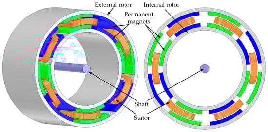
Figure 1.
Structure of the magnetic circuit of a double-rotor motor.
According to the assumptions, the motor considered dedicated to the fan drive should be characterised by the following data: 790 watts of maximum shaft power with continuous operation, 2150 rpm of maximum speed, 3.51 Nm of maximum torque with continuous operation corresponding to 2.33 Nm torque and 1780 rpm speed of AHRI rating point requirements and 80% efficiency at AHRI rating point (AHRI—Air-Conditioning, Heating and Refrigeration Institute). The average temperature in the motor winding should not exceed 80 degrees Celsius under operating conditions with maximum power. The outer diameter of the motor is 143 mm. This dimension was determined according to the requirements specified by the industrial partner. The multistage research into the development of a cost-effective new magnetic circuit structure of a coreless PMSM motor for a fan drive unit was carried out within the framework of a long-term cooperation with an industrial partner.
A parametric 3D numerical model of the motor was developed in the Ansys Maxwell environment. The model enables analysis of the effect of changing parameters that describe the structure of an electromagnetic circuit, such as the number of pole pairs p, the coil pitch span c, the coil height hc, the magnet pitch span PM, the magnet height hPM, the thickness and length of the motor hy1 and hy2 yokes Li of motor-on-motor performance—Figure 2. An exemplary field distribution determined using a 3D field model of electromagnetic phenomena is shown in Figure 3.
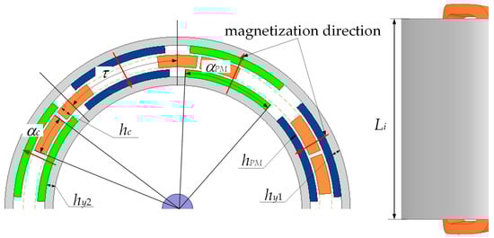
Figure 2.
Section of the magnetic circuit of the motor with an explanation of the introduced designations.
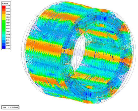
Figure 3.
Exemplary distribution of magnetic flux lines in studied motor.
Two parameters were proposed to assess the quality of the different motor design variants under consideration. The first parameter, Price in [$], determines the total cost of the motor, including estimated value based on prices, masses, machining and assembling overheads of electromagnetically active materials, such as permanent magnet (PM), back iron steel (Fe) and copper (Cu).
where PMm, Cum and Fem are the total mass of magnets, coils and yokes; PMk, Cuk and Fek are the coefficients of processing and assembly costs of electromagnetically active materials; and PMp, Cup and Fep are the prices of materials in $/kg. Machining and assembly costs were taken into account approximately using additional coefficients related to the unit costs of the materials used.
Price = PMm·PMk·PMp + Cum·Cuk·Cup + Fem·Fek·Fep
The second parameter, Costs, determines the cost of the motor per 1 Nm.
where Torque is the minimum value of the electromagnetic torque generated by the motor during rotation of the rotor.
The Costs parameter makes it easy to compare the manufacturing costs of motors differing in electromagnetic torque and in material, machining and assembly inputs. It is assumed that the best (optimum) solution is the one for which the lowest manufacturing costs expressed in the Costs parameter are obtained when the functional requirements and constraints are met.
In the design calculations, a constraint was imposed regarding the outer diameter, Do = 143 mm, of the motor. On the other hand, in order to take thermal requirements into account in an approximate manner, it was assumed that the permissible current density in the winding does not exceed 3.5 A/mm2. It was further assumed that the magnets are made of the material N38SH. At the initial stage of the design calculations, due to the high computational cost of the 3D FEA, the authors decided to develop and exploit a 2D numerical model of the proposed coreless motor assuming planar symmetry of the magnetic field distribution. The 2D models of coreless machines of different configurations of poles and coils were developed, that is, 8 poles/6 coils, 12 poles/9 coils, 16 poles/12 coils, 20 poles/15 coils—Figure 4.
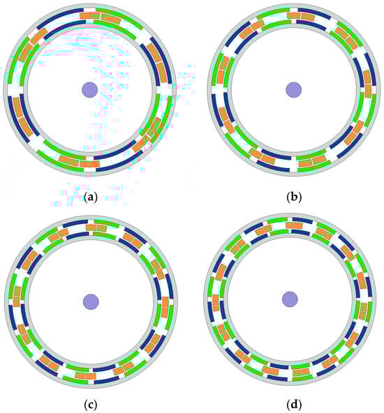
Figure 4.
Cross-sections of coreless machines: (a) 8 poles/6 coils, (b) 12 poles/9 coils, (c) 16 poles/12 coils, (d) 20 poles/15 coils.
Several different design variants were analysed to find the optimum motor electromagnetic circuit structure characterised by the lowest manufacturing costs, meeting the set functional requirements and constraints. The calculations were carried out in stages using a systematic review method. Variations included the height hc and the span αc of the coils, the length PM and the height hPM of the magnets, the number of pairs p, the thickness hy1 and hy2 of the steel rings in the outer and the length of the inner rotor and motor Li. The calculations were carried out assuming that the price of magnets is equal to $105 per kilogramme, the price of steel is equal to $1 per kilogramme and the price of copper is $7.9 per kilogramme.
Due to the extensiveness of the study, only selected results of the calculations are included in the paper in the form of graphs. A comparison of material and labour costs of magnetic circuit variants characterised by a different number of poles for the three selected coil heights hc is shown in Figure 5. It can be seen from the graph that the lowest costs for a motor with a maximum torque of T = 3.51 Nm are obtained for a magnetic circuit with 16 poles and 12 coils at a coil height of hc = 7.6 mm. The results presented in the following part of the work concern only the selected motor structure with 16 poles/12 coils.
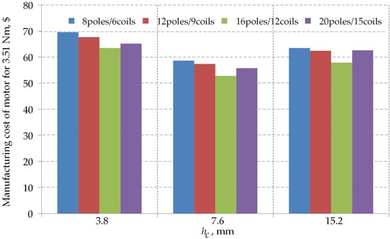
Figure 5.
Comparison of cost per 3.51 Nm of torque for all considered coreless motor designs.
The calculated dependencies of the electromagnetic torque Torque on the αc/αcmax parameter determining the coil side span and on the αPM/αPMmax parameter describing the magnet pitch span are presented in Figure 6a and Figure 6b, respectively. In doing so, it was assumed that for αPM = const (Figure 6a), the side span varies from 7 to 14 every 1 deg, where αcmax = 14 deg. In contrast, in Figure 6b, the span of the αPM magnet varies from 13 to 20 every 1 deg, where αPMmax = 22.5 deg is equal to the polar pitch of the motor. Figure 6c,d summarise the dependence of the Costs parameter on the coefficients αc/αcmax and αPM/αPMmax, respectively. On the other hand, in Figure 6e,f, the dashed lines indicate the estimated motor costs for the industrial partner’s required maximum motor torque value of T = 3.51 Nm. In summary, based on the analysis of the calculation results, it was found that the lowest cost of materials and labour is $52.80, and the magnetic circuit with such manufacturing costs has the following dimensions: hc = 7.6 mm, hPM = 6 mm, h y1 = hy2 = 10 mm, αc = 14 deg, αPM = 15 deg. The calculations further show that the axial length of the magnetic circuit Li = 60 mm and the masses of copper, magnets and steel are 1.51 kg, 0.375 kg and 1.61 kg, respectively. The number of turns in the coil is equal to 62.
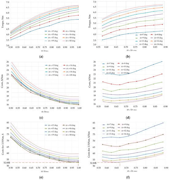
Figure 6.
The relations of torque and costs vs. coil thickness coefficient (b,d,f) and magnet thickness coefficient (a,c,e) for the design of 16 poles/12 coils and hc = 7.6 mm.
To verify the validity of the functional parameter calculations carried out for the lowest cost motor variant, a prototype was built, and a comparison of the calculation results with the experimental results is provided in Section 3, while an analysis of the second of the coreless synchronous machine structures with magnets made using die-casting technology developed by the authors and mentioned in the introduction is provided in Section 4.
3. Electromagnetic and Thermal Tests of a Prototype Coreless Motor with Sintered Magnets
To verify the suitability of the developed 2D model of the coreless motor with sintered magnets and the effectiveness of the proposed design approach, experimental tests of the built motor were performed. The design of 16 poles/12 coils was adopted for the development of the prototype motor. It was further assumed that the main dimensions of the magnetic circuit of the prototype motor are those of the least-cost motor variant indicated in Section 2. The main functional parameters determined in Section 2 for this motor variant are summarised in Table 1. The structure and cross-section of the constructed prototype motor are shown in Figure 7, while photographs of selected motor components are included in Figure 8.

Table 1.
Selected functional parameters of the coreless motor.
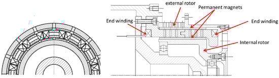
Figure 7.
Structure of the developed coreless motor prototype.
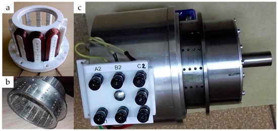
Figure 8.
Description of components of the prototype motor: (a) stator, (b) external rotor with magnets and (c) completed prototype of coreless motor.
These tests were carried out on a specially designed and built test stand—Figure 9. The developed stand consists of a B&R 8LSA servo drive, an MT5 torque sensor, a programmable power supply and a high-end digital oscilloscope as a data acquisition system.
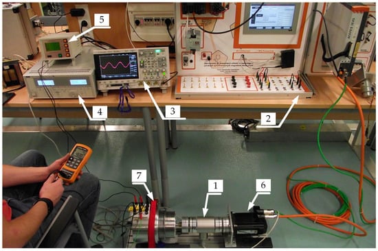
Figure 9.
The test stand: 1—torque sensor, 2—drive control system, 3—oscilloscope, 4—programmable power supply, 5—measured interface of torque meter, 6—servo motor, 7—prototype motor.
In the first stage of laboratory tests, selected values of the motor’s functional parameters, such as open-circuit induced voltages at the motor terminals (E12, E23, E31), as well as torque–angle characteristics, were measured and compared with results obtained during simulation tests. A comparison of the measured (meas) and calculated (calc) voltage waveforms for the rotor speed n = 2150 rpm is shown in Figure 10. On the contrary, Figure 11 shows a comparison of the calculated (calc) and measured (meas) characteristics of the electromagnetic torque as a function of the angular position for current values equal to 1.5, 3 and 4.5 A, respectively. It should be noted that, due to the lack of slots, there is no cogging torque in the motor.
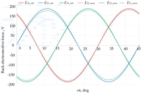
Figure 10.
Comparison of the calculated and measured line-to-line beck electromotive force (BEMF) waveforms, where ω = 225.15 rad/s.

Figure 11.
Comparison of the calculated and measured electromagnetic torque versus rotor angular position for different values of phase current.
To determine the relative difference between the measured and calculated results, the factor Δd% was introduced,
where dmeas and dclac are the results obtained from the measurements and calculations, respectively.
By analysing the values shown in Figure 10 and Figure 11, it can be seen that the percentage difference (3) between the results of the calculations and measurements does not exceed 6.19% for electromagnetic torque and 5.40% for line-to-line voltage.
The differences between the calculated and measured values are mainly due to the replacement of the ring-shaped magnets in the prototype motor with a set of many small perpendicular magnets. The use of multiple cubic magnets in the motor resulted in a lower magnetic flux than that produced by the ring-shaped magnets. In addition, a second important reason for the discrepancy between calculation and measurement results is the use of a two-dimensional instead of a three-dimensional model of magnetic phenomena in the motor in the calculations.
In the second stage of the study, a motor load test was carried out. The voltages at the winding terminals (U12, U23, U31), the currents in the winding (I1, I2, I3) and input power (Pin) were measured. Based on the results obtained from the torque and speed, the nominal power value on the motor shaft (Pout) was calculated, and the efficiency of the motor (η) was determined. During the measurements, the rotor rotated at 2150 rpm and was loaded with a torque of 0 to 3.51 Nm. The test bench for the motor load test is shown in Figure 12, with a converter (1) to supply the motor under test (2), an MT5 torque sensor to measure torque and speed (3) and an eddy current brake (4). Measurements of electrical quantities were performed using a class A power quality analyser. The results obtained are summarised in Table 2.
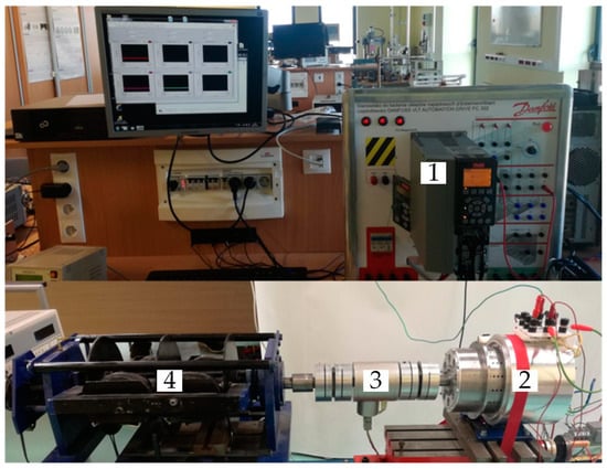
Figure 12.
Test stand: 1—converter, 2—coreless motor, 3—torque and speed transducer, 4—eddy current brake.
Table 2.
Selected functional parameters.
In the next stage of tests, selected motor thermal tests were carried out. First, the temperature course was determined at selected points on the motor during the machine heating test. These points are highlighted in colour on the motor cross-section shown in Figure 10. The temperature at these points was measured using resistance sensors PT 100 and a high-precision data acquisition system by National Instruments. The course of temperature rises in the motor under maximum load (3.51 Nm) are shown in Figure 13.
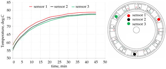
Figure 13.
Increases in temperature in the stator winding for the chosen points and Tmax = 3.51 Nm and location of sensors in the motor.
During the heating test, the surface temperature of the motor was also monitored using a FLIR T62101 thermal camera. The recorded temperature distributions obtained for a load torque value of Tmax = 3.51 Nm and a speed of 2150 rpm are shown in Figure 14a (t = 0) and Figure 14b (t = 42 min), respectively. For time t = 42 min, the temperature stabilised.

Figure 14.
Distribution of the temperatures on the motor surface and the temperatures at the chosen points for Tmax = 3.51 Nm, speed nmax = 2150 rpm for (a) t = 0 s and (b) t = 42 min.
The waveforms obtained show that after 41 min of operation, the temperature of the motor components begins to stabilise. It was found that after 42 min, the average temperature of the coils is about 78 °C, while the hottest spot of temperature on the frame surface of the motor is equal to 35.5 °C. The temperatures obtained do not pose a risk to the electro-insulation system and permanent magnets.
Tests carried out on the built prototype motor confirm the suitability of the developed new concept of a double-rotor magnetic circuit for use in coreless synchronous motors. Moreover, the good agreement between the experimental and simulation results confirms the reliability of the two-dimensional model of electromagnetic phenomena used in the calculations.
4. Analysis of the Magnetic Circuit of a Coreless Motor with Plastic-Bonded Magnets
At the suggestion of an industrial partner, an attempt was made to estimate the impact on motor manufacturing costs of replacing sintered magnets with magnets made using die-casting technology. The motivation for the study was the aim to reduce costs in the series production of motors. A modification to the magnetic circuit of the coreless motor, shown in Figure 4c, was proposed. This consisted of replacing the steel rings with bonded sintered magnets with rings made entirely of hard magnetic materials. The structure of the magnetic circuit of the double-rotor motor made of ring magnets is shown in Figure 15, where it was assumed that the ring magnets would be made by die-casting [33]. The undoubted advantage of this technology is that there is virtually no waste and no need to machine the rings. In addition, there is no need for steel rings and no magnet bonding process. The disadvantage, however, is the larger volume of hard magnetic material used.
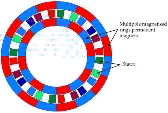
Figure 15.
Magnetic circuit structure of a motor with a double rotor formed by ring magnets.
In the considerations, the starting point was assumed to be an electromagnetic circuit with the dimensions and parameters optimised in Section 2. It was further assumed that the lengths in the axial direction of the ring magnets are 60 mm. Comparisons of motor manufacturing costs were carried out for two selected grades of hard magnetic materials for pressure-forming magnets, i.e., material TROMADYM 8480 (Max Baermann GMBH, Germany) based on neodymium and material TROMADUR 1525 PA12 (Max Baermann GMBH, Germany) based on ferrite magnets. The basic magnetic properties of these materials are summarised in Table 3, while detailed information on magnetic, thermal and mechanical properties is given in, among others, [33].
Table 3.
Key magnetic properties of materials TROMADYM 8480 and TROMADUR 1525 PA12.
Simulation studies of the considered two-rotor motor design with die-cast rotor were carried out using in-house software developed in the Borland-Delphi environment [34]. The software developed allows the magnetic field distribution, electromagnetic torque waveforms or induced electromagnetic forces to be calculated, taking into account the set temperature of the magnets. The calculation results obtained in the in-house programme were verified with those obtained using the Maxwell-Ansys package. The discrepancy between the results did not exceed 4%. Figure 16 shows a view of the user interface of the in-house software.
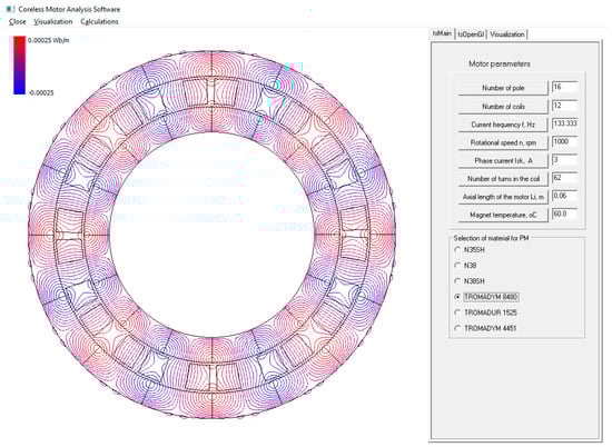
Figure 16.
View of the motor structure and magnetic field distribution in-house developed software.
A comparison of the electromagnetic torque characteristics as a function of rotor angular position for the motor designs under investigation is shown in Figure 17, while Figure 18 shows the induced line-to-line BEMF waveforms.
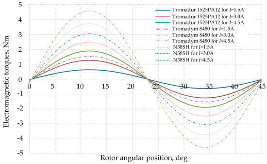
Figure 17.
The comparison of the electromagnetic torque characteristics versus rotor angular position for rotor made of Tromadym 8480, Tromadur 1525 PA12 and N38SH materials.
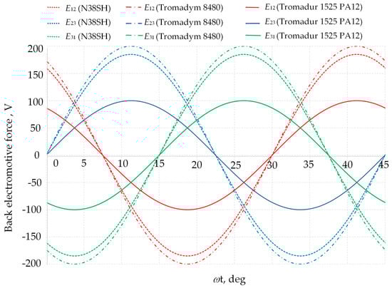
Figure 18.
Comparison of waveforms of the line-to-line beck electromotive force (BEMF) for the rotor made of materials Tromadym 8480, Tromadur 1525 PA12 and N38SH, where ω = 225.15 rad/s.
Based on the results obtained, it was found that the highest values of both the electromagnetic torque value and the induced BEMF in the winding of the considered motors were obtained for the motor with a rotor made of TROMADYM 8480 material.
In the next stage, studies were conducted to estimate the length Li of the motors with die-cast magnets, for which the same value of the maximum torque Tmax = 3.51 Nm was obtained as in the reference motor with N38SH magnets. To this end, in the calculations carried out using in-house developed software, the Li parameter was selected so that, at Iph = 4.25 A, a torque of Tmax = 3.51 Nm was obtained. The values obtained for the length Li for the considered are reported in Table 4.
Table 4.
The estimated values of motor length.
In the last stage, the cost of the motor components was estimated, assuming the lengths of the machines listed in Table 4. The quantities of materials used to produce the motors and their cost estimation are reported in Table 5, where the price per kilogram of Tromadym 8480 is $105 and Tromadur 1525 is $15.
Table 5.
Statement of mass and cost estimation.
Due to the difficulty in estimating the cost of casting the magnets, labour costs were not included. Nonetheless, the cost of making a motor with N38SH magnets of $52.80 (cost of materials and labour) is several times lower than the cost of the materials used to build die-cast magnet motors.
To reduce the cost of the materials used in the production of motors with ring magnets, it would be necessary to carry out optimisation calculations of the magnetic circuit similar to those presented in Section 2. In addition, a major disadvantage in the production of motors with magnets formed by die-casting is the very high price of the hard magnetic materials used for this purpose.
5. Conclusions
On the basis of requirements and work tasks specified by the industrial partner, a cost-effective magnetic circuit structure for a fan-driving unit was proposed. The coreless motors with sintered neodymium magnets of numbers of poles equal to 8, 12, 16 and 20 were analysed. Performed optimisation calculations using 2D field model of the machine allowed for the unit cost to be reduced significantly in relation to the initial designs. The performed FEA simulations showed that the most cost-effective design is a 16-pole coreless motor with sintered neodymium magnets. The selected motor was designed, manufactured and assembled, and it has been preliminary tested. The presented results show good concordance between the measured and simulated torque characteristics. It was found that the efficiency of the elaborated motor in both the rated operating conditions (AHRI) as well as the operating conditions with maximum power was equal to 79.5%, i.e., according to the industrial partner guidelines. The average value of temperature in the motor winding for maximum operating conditions (T = 3.51 Nm and n = 2150 rpm) did not exceed 80 degrees Celsius.
Coreless motor structures with N38SH sintered magnets, which were compared with dual-rotor motor structures with plastic-bonded magnet rotors using numerical models of the considered structures in a 2D space, were developed. The study used the author’s finite element method (FEM) code. The obtained results showed that the highest value of electromagnetic torque can be obtained for a motor with a rotor made of Tromadym 8480 material. However, on the basis of cost estimates of the motor designs under consideration, it was found that the cost of producing rotors from materials of type Tromadym 8480 and Tromadur 1525PA12 is much higher than the material costs for the motor with neodymium magnets and steel rotor.
Author Contributions
Conceptualisation, W.S. and M.B.; methodology, W.S.; software, W.S. and M.B.; validation, W.S., C.J. and M.B.; formal analysis, C.J.; investigation, M.B. and M.K.; resources, W.S.; data curation, M.B. and M.K.; writing—original draft preparation, M.B.; writing—review and editing, C.J. and W.S.; visualisation, M.B. All authors have read and agreed to the published version of the manuscript.
Funding
This research was funded by the Polish Government, grant number 0212/SBAD/0616.
Data Availability Statement
The data presented in this study are available on request from the corresponding author. The data are not publicly available due to the privacy policy of cooperating companies.
Conflicts of Interest
The authors declare no conflict of interest.
References
- Bi, Y.; Chai, F.; Chen, L. The Study of Cooling Enhancement in Axial Flux Permanent Magnet Motors for Electric Vehicles. IEEE Trans. Ind. Appl. 2021, 57, 4831–4839. [Google Scholar] [CrossRef]
- Abdelli, A.; Gilson, A.; Chareyron, B.; Zito, G. Combination of 2D and 3D Finite Element Models in the Design of Axial Flux Permanent Magnet Machines for Electric Vehicle Applications. In Proceedings of the 2023 IEEE Workshop on Electrical Machines Design, Control and Diagnosis (WEMDCD 2023), Newcastle upon Tyne, UK, 13–14 April 2023; pp. 1–6. [Google Scholar]
- Wang, X.; Lu, H.; Li, X. Winding Design and Analysis for a Disc-Type Permanent-Magnet Synchronous Motor with a PCB Stator. Energies 2018, 11, 3383. [Google Scholar] [CrossRef]
- Wang, X.; Li, T.; Cui, X.; Zhao, X. Design and Analysis of Coreless Axial Flux Permanent Magnet Machine with Novel Composite Structure Coils. Energies 2022, 15, 5162. [Google Scholar] [CrossRef]
- Rebelo, J.M.G.; Silvestre, M.Â.R. Development of a Coreless Permanent Magnet Synchronous Motor for a Battery Electric Shell Eco Marathon Prototype Vehicle. Open Eng. 2018, 8, 382–390. [Google Scholar] [CrossRef]
- Sun, X.; Shi, Z.; Lei, G.; Guo, Y.; Zhu, J. Analysis and Design Optimization of a Permanent Magnet Synchronous Motor for a Campus Patrol Electric Vehicle. IEEE Trans. Veh. Technol. 2019, 68, 10535–10544. [Google Scholar] [CrossRef]
- Besong, J.E.; Fujimoto, Y. Design of a Coreless Multi-Phase Electric Motor Using Magnetic Resonant Coupling. IEEE Trans. Magn. 2022, 58, 1–11. [Google Scholar] [CrossRef]
- Huang, C.; Kou, B.; Zhao, X.; Niu, X.; Zhang, L. Multi-Objective Optimization Design of a Stator Coreless Multidisc Axial Flux Permanent Magnet Motor. Energies 2022, 15, 4810. [Google Scholar] [CrossRef]
- Barba, P.D.; Bonislawski, M.; Palka, R.; Paplicki, P.; Wardach, M. Design of Hybrid Excited Synchronous Machine for Electrical Vehicles. IEEE Trans. Magn. 2015, 51, 1–6. [Google Scholar] [CrossRef]
- Wang, X.; Li, X.; Li, C.; Xu, S.; Ling, L. Design of a PCB Stator Coreless Axial Flux Permanent Magnet Synchronous Motor Based on a Novel Topology Halbach Array. Front. Inf Technol Electron. Eng 2019, 20, 414–424. [Google Scholar] [CrossRef]
- Gao, B.; Cheng, Y.; Wang, Y.; Zhao, T.; Ding, L.; Cui, S.; Liu, X.; Shi, Y. Optimal Design of PCB Coreless Axial Flux Permanent Magnet Synchronous Motor With Arc Windings. IEEE Trans. Energy Convers. 2023, 39, 567–577. [Google Scholar] [CrossRef]
- Kesgin, M.G.; Han, P.; Taran, N.; Lawhorn, D.; Lewis, D.; Ionel, D.M. Design Optimization of Coreless Axial-Flux PM Machines with Litz Wire and PCB Stator Windings. In Proceedings of the 2020 IEEE Energy Conversion Congress and Exposition (ECCE 2020), Detroit, MI, USA, 11–15 October 2020; IEEE: Detroit, MI, USA, 2020; pp. 22–26. [Google Scholar]
- Karabulut, Y.; Meşe, E. Torque Performance Comparison Between Slotted and Non-Slotted Axial Flux PCB Winding Machine. In Proceedings of the 2021 IEEE 19th International Power Electronics and Motion Control Conference (PEMC 2021), Gliwice, Poland, 25–29 April 2021; pp. 519–523. [Google Scholar]
- Wang, X.; Li, T.; Gao, P.; Zhao, X. Design and Loss Analysis of Axial Flux Permanent Magnet Synchronous Motor with PCB Distributed Winding. In Proceedings of the 2021 24th International Conference on Electrical Machines and Systems (ICEMS 2021), Gyeongju, Republic of Korea, 31 October–3 November 2021; pp. 1112–1117. [Google Scholar]
- Komeza, K.; Lefik, M.; Juszczak, E.N.; Roger, D.; Takorabet, N.; Meibody-Tabar, F. Analysis of the Impact of the Design of HT Machines on the Cogging Torque and Losses in Permanent Magnets. In Proceedings of the 2016 IEEE International Conference on Power Electronics, Drives and Energy Systems (PEDES 2016), Trivandrum, India, 14–17 December 2016; pp. 1–6. [Google Scholar]
- Roger, D.; Takorabet, N. Topologies of High Temperature Machines. In Proceedings of the 2020 IEEE 14th International Conference on Compatibility, Power Electronics and Power Engineering (CPE-POWERENG 2020), Setúbal, Portugal, 8–10 July 2020; Volume 1, pp. 324–329. [Google Scholar]
- Gercekcioglu, H.S.; Akar, M. Optimal Rotor Design of Novel Axial Flux Synchronous Reluctance Motor and Validation. Int. Trans. Electr. Energy Syst. 2021, 31, e12866. [Google Scholar] [CrossRef]
- Nishanth, F.; Van Verdeghem, J.; Severson, E.L. A Review of Axial Flux Permanent Magnet Machine Technology. IEEE Trans. Ind. Applicat. 2023, 59, 3920–3933. [Google Scholar] [CrossRef]
- Zhao, J.; Liu, X.; Wang, S.; Zheng, L. Review of Design and Control Optimization of Axial Flux PMSM in Renewable-Energy Applications. Chin. J. Mech. Eng. 2023, 36, 45. [Google Scholar] [CrossRef]
- MacManus-Driscoll, J.L.; Wimbush, S.C. Processing and Application of High-Temperature Superconducting Coated Conductors. Nat. Rev. Mater. 2021, 6, 587–604. [Google Scholar] [CrossRef]
- Chaudhary, V.; Mantri, S.A.; Ramanujan, R.V.; Banerjee, R. Additive Manufacturing of Magnetic Materials. Prog. Mater. Sci. 2020, 114, 100688. [Google Scholar] [CrossRef]
- Mohapatra, J.; Xing, M.; Elkins, J.; Liu, J.P. Hard and Semi-Hard Magnetic Materials Based on Cobalt and Cobalt Alloys. J. Alloys Compd. 2020, 824, 153874. [Google Scholar] [CrossRef]
- Borghei, M.; Ghassemi, M. Insulation Materials and Systems for More- and All-Electric Aircraft: A Review Identifying Challenges and Future Research Needs. IEEE Trans. Transp. Electrif. 2021, 7, 1930–1953. [Google Scholar] [CrossRef]
- Sudhoff, S.D.; Kuhn, B.T.; Corzine, K.A.; Branecky, B.T. Magnetic Equivalent Circuit Modeling of Induction Motors. IEEE Trans. Energy Convers. 2007, 22, 259–270. [Google Scholar] [CrossRef]
- Khang, H.V.; Arkkio, A. Eddy-Current Loss Modeling for a Form-Wound Induction Motor Using Circuit Model. IEEE Trans. Magn. 2012, 48, 1059–1062. [Google Scholar] [CrossRef]
- Luo, X.; Liao, Y.; Toliyat, H.A.; El-Antably, A.; Lipo, T.A. Multiple Coupled Circuit Modeling of Induction Machines. IEEE Trans. Ind. Appl. 1995, 31, 311–318. [Google Scholar] [CrossRef]
- Ba, X.; Gong, Z.; Guo, Y.; Zhang, C.; Zhu, J. Development of Equivalent Circuit Models of Permanent Magnet Synchronous Motors Considering Core Loss. Energies 2022, 15, 1995. [Google Scholar] [CrossRef]
- Williamson, S.; McClay, C.I. Optimization of the Geometry of Closed Rotor Slots for Cage Induction Motors. IEEE Trans. Ind. Appl. 1996, 32, 560–568. [Google Scholar] [CrossRef]
- Hameyer, K.; Belmans, R. Numerical Modelling and Design of Electrical Machines and Devices; WIT Press: Southampton UK, 1999; ISBN 978-1-85312-626-0. [Google Scholar]
- Mahmoudi, A.; Kahourzade, S.; Rahim, N.A.; Hew, W.P. Design, Analysis, and Prototyping of an Axial-Flux Permanent Magnet Motor Based on Genetic Algorithm and Finite-Element Analysis. IEEE Trans. Magn. 2013, 49, 1479–1492. [Google Scholar] [CrossRef]
- Gieras, J.F.; Piech, Z.J.; Tomczuk, B. Linear Synchronous Motors: Transportation and Automation Systems, 2nd ed.; CRC Press: Boca Raton, FL, USA, 2016; ISBN 978-1-4398-4222-5. [Google Scholar]
- Demenko, A. Time-Stepping FE Analysis of Electric Motor Drives with Semiconductor Converters. IEEE Trans. Magn. 1994, 30, 3264–3267. [Google Scholar] [CrossRef]
- Cassing, W.; Kuntze, K.; Ross, G. Dauermagnete: Mess- und Magnetisiertechnik; Expert Verlag: Renningen, Germany, 2017; ISBN 978-3-8169-3419-6. [Google Scholar]
- Baranski, M.; Szelag, W.; Lyskawinski, W. Analysis of the Partial Demagnetization Process of Magnets in a Line Start Permanent Magnet Synchronous Motor. Energies 2020, 13, 5562. [Google Scholar] [CrossRef]
Disclaimer/Publisher’s Note: The statements, opinions and data contained in all publications are solely those of the individual author(s) and contributor(s) and not of MDPI and/or the editor(s). MDPI and/or the editor(s) disclaim responsibility for any injury to people or property resulting from any ideas, methods, instructions or products referred to in the content. |
© 2024 by the authors. Licensee MDPI, Basel, Switzerland. This article is an open access article distributed under the terms and conditions of the Creative Commons Attribution (CC BY) license (https://creativecommons.org/licenses/by/4.0/).