Article

Heat Transfer and Flow Resistance in Crossflow over Corrugated Tube Banks

1
School of Aeronautic Science and Engineering, Beihang University, Beijing 100191, China
2
Xinxiang Aviation Industry (Group) Co., Ltd., Xinxiang 453049, China
*
Author to whom correspondence should be addressed.
Energies 2024, 17(7), 1641; https://doi.org/10.3390/en17071641
Submission received: 3 February 2024 / Revised: 18 March 2024 / Accepted: 26 March 2024 / Published: 29 March 2024
(This article belongs to the Section J1: Heat and Mass Transfer)

Abstract

:
The engineering of tubes with surface corrugations is recognized as an effective method for enhancing heat transfer within the tube. Yet the impact of surface corrugation on the flow and heat transfer around the tube’s exterior remains inadequately explored. This study investigates the crossflow and heat transfer characteristics in banks of periodically inward-corrugated tubes using computational fluid dynamics. Numerical simulations were performed for both in-line and staggered tube arrangements, covering Reynolds numbers from 1000 to 10,000. The aim was to examine how various corrugation parameters affect heat transfer and flow dynamics in tube banks configured in both in-line and staggered layouts. The results show that the heat transfer and the pressure drop in crossflow across tube banks are substantially influenced by changes in corrugation parameters. Specifically, in the in-line arrangement, both the Nusselt number and Euler number decrease significantly as the corrugation height increases. In contrast, in the staggered arrangement, the Nusselt number and Euler number exhibit less variation in response to surface corrugation. A comparative analysis of performance criteria suggests that a staggered arrangement is more advantageous for improving thermal–hydraulic efficiency in crossflow through corrugated tube banks.

1. Introduction

Heat exchangers serve as essential elements in thermal systems responsible for enabling heat transfer between various fluid media. Their applications span multiple engineering sectors, including energy, chemical engineering, automotive, and aerospace. Among the various types of heat exchangers, tubular designs like shell-and-tube and tube-and-fin are the most prevalent. These types have seen extensive development and refinement over many decades, making them a mature and reliable choice in heat exchange technology [1,2].
In heat exchanger applications, multiple tubes can be positioned in various configurations, such as in parallel, in-line, or staggered configurations, which are always referred to as tube banks. The primary purpose of a tube bank is to maximize the surface area available for heat transfer between two fluids, where one fluid flows inside the tubes and the other flows outside, i.e., around the tubes. Tube banks are commonly found in shell-and-tube designs, where one fluid flows through the tubes (the tube side) and the other fluid flows across the tubes within a larger shell (the shell side). The efficiency of heat transfer in such equipment depends on the layout of the tube bank, as well as the shape of the tubes.
The configuration of a tube bank is a key factor in determining the operational performance of a heat exchanger. This includes aspects such as the rate of heat transfer, power consumption, and structural vibrations and noise. The crossflow passing over tube banks introduces complex flow phenomena, characterized by the creation of shear layers on the tubes, the separation of boundary layers, the formation of recirculation wakes, and interactions between these wakes. These intricate flow behaviors play a non-trivial role in defining the overall efficiency of heat exchangers [3].
Tube banks with circular smooth tubes are widely used in tubular heat exchangers for their simplicity and ease of manufacture. Grimson [4] and Zukauskas [5] concentrated on the fluid dynamics of smooth circular (SC) tube banks, offering useful correlations for predicting the heat transfer coefficient in both staggered and in-line arrangements. Khan et al. [6] developed an analytical approach to examine crossflow and heat transfer in tube banks under isothermal boundary conditions. Wilson et al. [7] introduced a model for predicting the pressure drop and heat transfer coefficient in both laminar and turbulent air flow through SC tube banks, utilizing two-dimensional elliptic flow. Their analysis addressed the impacts of Reynolds numbers and tube arrangements on local/global Nusselt numbers, friction factors, temperature field, velocity field, and flow profiles, showing good agreement with existing experimental data. El-Shaboury et al. [8] conducted numerical simulations to study the flow and heat transfer in a five-row in-line SC tube banks with entrance and exit sections at low Reynolds numbers. They observed higher heat transfer rates around the first tube compared to subsequent ones and noted repetitive flow patterns from the third row, indicating rapid flow development in a tube bank. Zhang et al. [9] investigated oblique laminar flow and convective heat transfer across a tube bank under constant wall heat flux conditions, finding that both friction factor and the Nusselt number increased with the angle of oblique fluid flow.
Although they are easy to manufacture and cost-effective, the smooth tubes suffer from poor heat transfer efficiency, which demands the utilization of heat transfer enhancement techniques to improve their heat transfer coefficient within the tube. This inspires a lot of research in this field. There has been an increasing research focus on tubular heat transfer enhancement such as elliptical tubes, corrugated tubes, and skew tubes. These modified tubes have been proved to promote secondary flow inside the tube and significantly improve the heat transfer coefficient. However, the majority of research has primarily concentrated on investigating the advantages of heat transfer augmentation within enhanced tubes, often overlooking the impact on flow and heat transfer modifications on the exterior side of the tube. This oversight is non-trivial in scenarios where the flow passage within the tube bank is altered as a result of variations in tube geometries.
Several studies have explored the convective heat transfer and crossflow around non-circular tube banks, involving flat/elliptic, oval, twisted, and finned tubes [10]. A group of investigations [11,12,13,14] focused on heat transfer and pressure drop across elliptic tubes, generally indicating significant differences in thermal–hydraulic performance between smooth circular and elliptic tube banks. In particular, the angle of attack in the crossflow and the aspect ratio of elliptic tubes are critical factors.
Recent research has also examined oval tube banks, as oval-shaped cylinders exhibit lower flow resistance in crossflow than circular ones. Merker and Hanke [15] conducted an experimental study on the heat transfer and pressure drop in tube banks with oval and circular tubes, finding that oval tubes have a lower heat transfer coefficient and reduced flow resistance. They concluded that oval tube banks, with their smaller frontal areas on the shell side compared to circular tubes, are advantageous when shell-side pumping power is limited. Tang et al. [16] studied the thermal–hydraulic characteristics of crossflow in twisted oval tube bundles, revealing a 13.6–20.6% enhancement in heat transfer compared to smooth tubes at equivalent pump power, attributed to increased vortex generation. Conversely, Li et al. [17] found that twisted oval tubes increase both heat transfer coefficient and pressure drop, highlighting the impact of tube twisting on heat transfer and flow resistance in oval tube banks.
Finning the exterior of tubes is an effective method by which to reduce heat transfer resistance in tube banks. Sparrow and Kang [18] used longitudinal fins on circular tubes, increasing heat transfer rates and slightly reducing pressure drop compared to un-finned tubes. With fins at both ends, there was an increase in both heat transfer rate and pressure drop. Lemouedda [19] advocated for a serrated finned-tube design, showing superior performance over full fins for the same heat transfer area. These studies suggest that finned tubes create more complex flow patterns around the tube bank and expand the heat transfer area, effectively lowering thermal resistance but at the cost of higher pressure drop.
The existing body of literature extensively explores the heat transfer and crossflow characteristics in tube banks with smooth tubes with a constant cross-section, i.e., the circular tube, the oval tube, the twisted tube. However, there is a gap in the research concerning the heat transfer characteristics in crossflow around corrugated tube banks when tube has a varied cross-sectional area. Specifically, the study of crossflow and heat transfer in tube banks with periodically inward-corrugated (PIC) tubes remains unexplored. Addressing this research gap, our study serves as a pioneering investigation into the crossflow and heat transfer characteristics in PIC tube banks, considering both in-line and staggered configurations. We conducted comprehensive parametric studies to assess the impact of different corrugation geometric parameters on the thermal–hydraulic efficiency of these tube banks.
This paper is structured as follows: Section 1 provides an overview of the current state of the art in this field. In Section 2, the numerical model and the configurations used for simulations are detailed. Section 3 presents the results and discussions. The paper concludes with Section 4, which summarizes the key findings and observations derived from the research.

2. Numerical Model

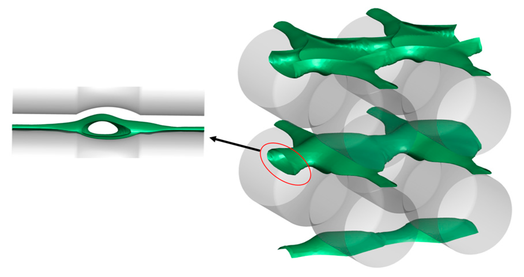
2.1. Description of the Tube Geometry

The tube banks are composed of multiple rows of pipes, aligned either parallel or perpendicular to the flow direction, with the latter configuration known as the crossflow setup. Tubes are organized in either an in-line or staggered formation, as depicted in Figure 1. The ratios of transverse  ( S T = L T / D )  and longitudinal  ( S L = L L / D )  spacing between the tubes are crucial for defining the properties of the tube bank. In this study, the tube bank is designed with relatively small values of  S T  and  S L , both being 1.25. A heat exchanger with such compact dimensions of spacing is classified as a compact heat exchanger, in accordance with Zukauskas and Ulinskas [20].
This study utilizes PIC tubes in the tube bank. Figure 2 illustrates the schematic of an individual PIC tube. The PIC tube’s geometry is defined by four parameters: inner diameter (D), periodic length between corrugations (P), corrugation height (H), and corrugation width (W). The latter three, which specifically describe the corrugation, are normalized to the tube’s diameter, resulting in three independent dimensionless parameters. This study investigates the convective heat transfer in crossflow over tube banks, considering different geometric parameters of the PIC tubes, and examines both in-line and staggered arrangements. The range of parameters considered for the PIC tubes is outlined in Table 1.

2.2. Governing Equations and Data Reduction

We solve incompressible Reynolds-averaged Navier–Stokes equations and the energy equation, written as
u ¯ i x i = 0 ,
ρ u i t + ρ ( u i u j ) x j = p x i + x j [ μ ( u i x j + u j x i 2 3 δ i j u j x j ) ] + x j ( ρ u i u j ¯ ) ,
t ( ρ E ) + x i ( u i ρ E + u i p ) = x i [ ( λ + c p μ t Pr t ) T x i + μ u i ( u i x j + u j x i 2 3 δ i j u j x j ) ] .
The shear stress transport (SST) model [21] was chosen to address the closure of Reynolds stress terms. This turbulence model has demonstrated exceptional performance in simulating external flows around tube banks, as evidenced in references [22,23]. The governing equations of the SST model are formulated as follows:
t ( ρ k ) + x i ( ρ k u i ) = x j [ ( μ + μ t σ k ) k x j ] + μ t S 2 ρ β 1 k ω ,
t ( ρ ω ) + x i ( ρ ω u i ) = x j [ ( μ + μ t σ ω ) ω x j ] + α ρ S 2 ρ β 2 ω 2 + 2 ( 1 F 1 ) ρ 1 ω σ ω , 2 k x j ω x j .
In the context of fluid crossflow over tube banks, Re is typically defined as
R e = ρ D u max μ ,
where D is the outer diameter of the tube and  u max  is the maximum flow velocity in the gap of tube banks. The  u max  for the in-line arrangement can be calculated by
u max = u S T S T 1 .
The  u max  for the staggered arrangement is defined as follows:
u max = u S T 2 ( S D 1 ) ,
where  S D = ( S T / 2 ) 2 + S L 2  represents the diagonal pitch ratio in staggered arrangements. The  u max  takes the same form as in-line arrangement when  ( S D D ) ( S T D ) / 2  [24].
The Euler number, Eu, is usually used to characterize the pressure loss coefficient in tube banks, which is defined as
E u = 2 Δ p N ρ u max 2 ,
where N is the number of tube rows in the flow direction and  Δ p  is the pressure drop.
The total heat transfer Q of the fluid is expressed as
Q = q A = c p q m ( T o u t T i n ) ,
where A is the heat exchange area of the tube,  q m  is the mass flow rate, and  T i n  and  T o u t  are the fluid inlet and outlet temperature, respectively.
The expression of convective heat transfer coefficient is defined as
h = q Δ T ,
where  Δ T  is the logarithmic mean temperature difference and is expressed as
Δ T = T i n T o u t ln ( T w T i n T w T o u t ) .
Then, the Nusselt number Nu can be calculated via
N u = h a v g D λ .

2.3. Boundary Conditions and Numerical Approaches

Simulating a full-scale tube bank with hundreds of tubes would be extremely time-consuming and expensive. Previous studies have shown that flow development within a tube bank occurs rapidly, achieving a fully developed state after passing through just a few rows of tubes. Therefore, examining the fully developed flow and characteristics of tube banks is of significant practical relevance, as it can effectively represent the performance of entire tube banks. Based on these considerations, this study focuses on investigating the flow and heat transfer characteristics of a PIC tube bank under fully developed conditions. The tube diameter (D) is maintained at 0.003 m, and the maximum flow velocity umax are 4.87 m/s, 9.74 m/s, 24.35 m/s, 34.08 m/s, and 48.69 m/s, respectively. The length of the PIC tube is defined as L = W + P. Periodic boundary conditions are implemented in both longitudinal and transverse flow directions. Mass flux  q m  is designated along the longitudinal direction, its magnitude derived from the Reynolds number using the following equation:    q m = ρ u max A min = ρ A min R e μ ρ D = A min R e μ D . Once the mass flux is ascertained, the pressure drop can be calculated through an iterative process. Moreover, a condition of zero net mass flux is imposed in the transversal direction, leading to no pressure drop across this axis. The bulk fluid inlet temperature is 300 K, while the corrugated walls are maintained with a no-slip boundary condition and a constant wall temperature of 310 K. Air at room temperature is used as the working fluid in the simulations with the assumption that its physical properties remain constant throughout the computational domain. The specific fluid properties are as follows:  ρ = 1.225   k g/m3 c P = 1006.43 J/(kg·K), and  ν =  1.46 × 10⁻⁵ m2/s, which yields a Prandtl number of 0.74. The mass flow rate in the longitudinal direction is predetermined based on the Reynolds number. The required pressure gradient is determined through an iterative process.
To solve the governing equations along with the associated boundary conditions, the finite volume solver ANSYS Fluent was employed. The SIMPLE algorithm was used to effectively tackle pressure and velocity coupling problems. For spatial discretization, second-order upwind schemes were utilized for momentum and energy equations, while a second-order implicit scheme was adopted for temporal discretization. The convergence residual of the energy equation is 10−7, while the residuals of the other equations are 10−5.

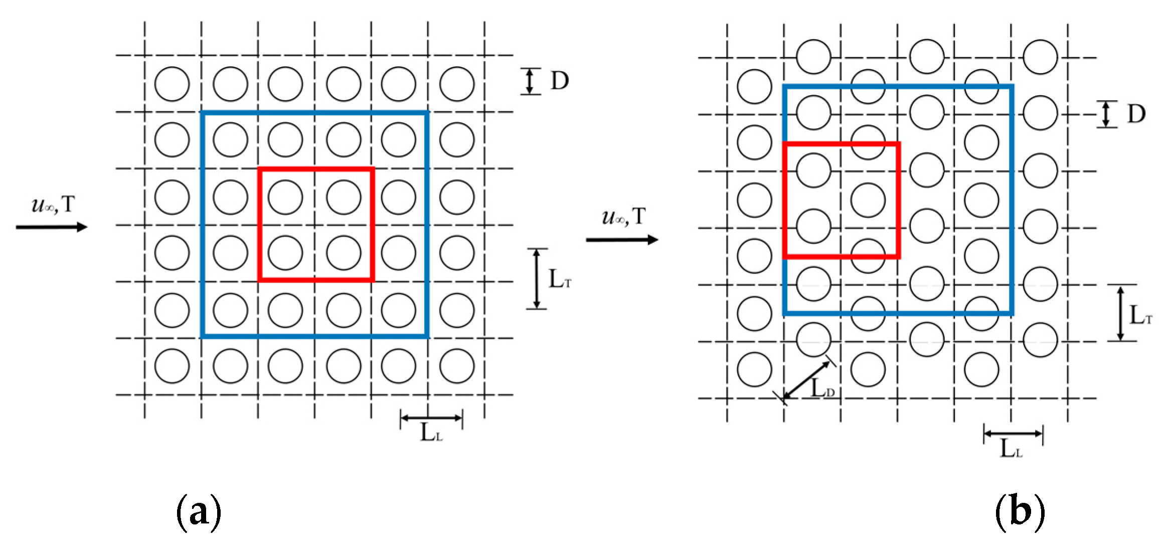
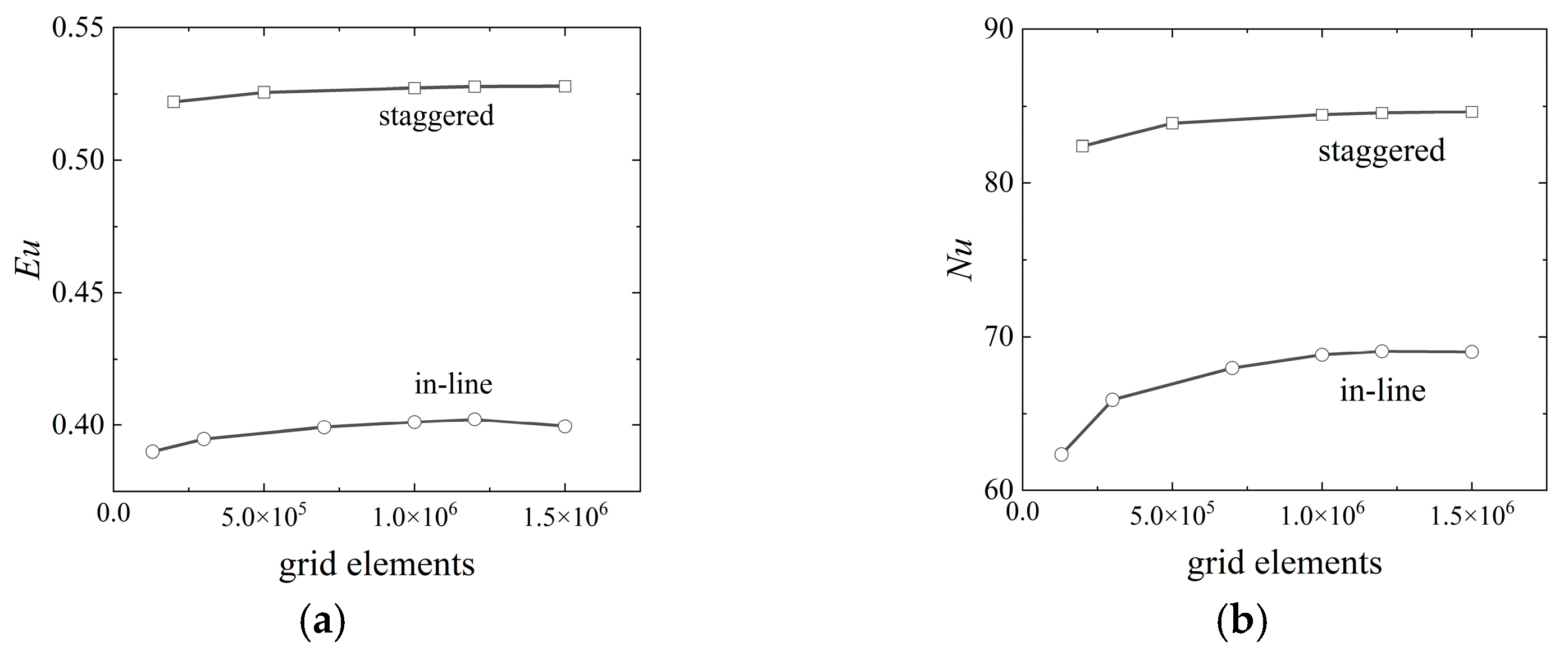
2.4. Computational Domain and Grid Dependency Analysis

Tube banks consist of repeating geometric units, enabling the consideration of only partial tube rows in numerical simulations to improve computational efficiency. Thus, assessing the simulation results’ sensitivity to the size of the computational domain is crucial. Figure 1 displays two distinct computational domains with designated tube row sizes of 4 × 4 and 2 × 2, respectively, each representing a repetitive element unit extracted from the tube banks. The flow and heat transfer characteristics within these two domains, in both in-line and staggered configurations, were analyzed. Table 2 presents the computed Euler number (Eu) and Nusselt number (Nu) for these domains. In the in-line 4 × 4 domain, Eu and Nu values were found to be 0.14% and 0.47% higher, respectively, than those in the in-line 2 × 2 domain. In contrast, for the staggered arrangement, the differences were 0.17% and 0.98%, respectively. In both in-line and staggered configurations, the results from the 2 × 2 domain showed less than 1% deviation compared to the 4 × 4 domain. Therefore, for efficiency, the 2 × 2 computational domain was selected for further computations in this study. The size of the computation domain is 2LT × 2LL × L.
Figure 3 shows the hexahedral mesh designed within the 2 × 2 computational domain. To achieve accurate simulation of the flow and heat transfer, particularly within the boundary layer, the mesh near the tube walls has been meticulously refined. The height of the first layer at the near-wall grids is 0.003 mm, with a growth ratio of 1.1, ensuring that y+ < 1 for Re = 10,000. The mesh quality was assessed based on two criteria: the determinant and angle criteria. In our simulation, the minimum determinant and the minimum angle criteria for all the computed cases surpass 0.68 and 43°, respectively. For both in-line and staggered configurations, grid independence was verified through simulations using six and five different mesh densities, respectively.
Figure 4 presents comparisons of the Euler number (Eu) and Nusselt number (Nu) across various mesh sizes, specifically for the case with a corrugation geometry of H/D = 2/16, W/D = 1, and P/D = 2 at a Reynolds number (Re) of 10,000. The results indicated that variations in Eu and Nu were negligible once the mesh size exceeded 1,000,000 cells. Consequently, a mesh with 1,000,000 cells was deemed adequate for ensuring grid independence in the simulations.

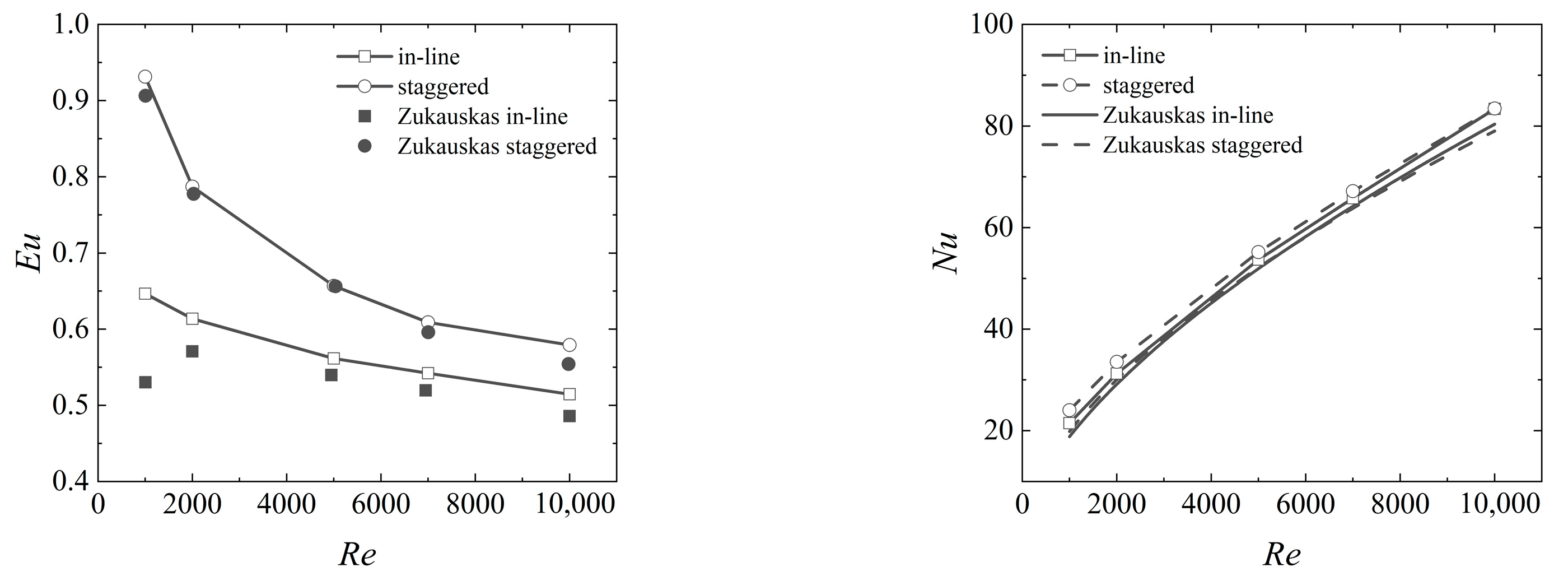
2.5. Validation of Numerical Simulations

To verify the accuracy of our numerical model, we performed simulations of crossflow over smooth circular tube banks and compared these results with Zukauskas’s established data and empirical correlations [5]. His Nu correlation is given as
in-line :       N u = 0.27 R e 0.63 P r f 0.36 ( P r f / P r w ) 0.25 ,                                     1000 < R e < 2 × 10 5 ;                  
staggered :       N u = 0.35 ( L T L L ) 0.2 R e 0.6 P r 0.36 ( P r f / P r w ) 0.25 , L T L L 2 ,       1000 < R e < 2 × 10 5 .
The comparative outcomes are depicted in Figure 5. In the in-line arrangement, the discrepancy between the Euler number (Eu) from our simulations and Zukauskas’s experimental data ranges from 3.8% to 17.9%, while for the staggered arrangement, this deviation lies between 0.1% and 4.3%. Additionally, the difference in the Nusselt number (Nu) between our simulations and the Zukauskas correlation ranges from 2.4% to 12.3% in the in-line arrangement and between 5% and 17.3% in the staggered arrangement.
The most significant discrepancies are observed in the Eu number comparisons, particularly at low Reynolds numbers (Re). However, except for the case of Re = 1000, the deviation remains below 7% for both in-line and staggered arrangements. Overall, the comparisons in Figure 5 demonstrate a good agreement between our numerical results and Zukauskas’s correlation and experimental data, thereby validating the reliability of our numerical models and solution methods.

3. Results and Discussion

3.1. PIC Tube Banks in In-Line Arrangement

In this section, we discuss the results of Euler (Eu) and Nusselt (Nu) numbers for PIC tube banks. Our primary focus is to compare PIC tube banks with the reference SC tube banks, highlighting performance variations caused by changes in tube geometry. To ensure a fair comparison of thermal–hydraulic performances, we used the performance evaluation criteria (PEC) [25] for comparing PIC tube banks with SC tube banks under identical pumping power conditions. PEC is specifically defined in terms of the Nusselt and Euler numbers of the reference SC tube banks.
P E C = N u / N u 0 ( E u / E u 0 ) 1 / 3 ,
where  N u 0  and  E u 0  are the Nusselt number and Euler number of the reference SC tube banks, respectively.
Figure 6 shows the variation in Eu and Nu in relation to the H/D ratio for Reynolds numbers (Re) ranging from 1000 to 10,000. Strikingly, PIC tube banks exhibit lower Eu and Nu compared to SC tube banks. An increase in corrugation height (H/D) from 1/16 to 3/16 leads to a significant decrease in both Eu and Nu. For H/D = 3/16, the Eu and Nu of the PIC tube banks are approximately 0.60 and 0.71 times lower than those of the SC tube banks, respectively, within the examined Re range. The PEC, apparently lower than unity, suggests a general decline in thermal–hydraulic performance when substituting SC tube banks with PIC tube banks in an in-line arrangement.
To understand why PIC tube banks yield lower heat transfer and flow resistance, we analyzed the flow and thermal fields. Figure 7 shows normalized velocity and temperature contours at the flow direction for an in-line arrangement of the PIC tube bank at Re = 10,000. The velocity is normalized to  u max , defined as  u * = u / u max . The normalized temperature θ is defined as  θ = ( T T w ) / ( T i n T w ) . Figure 8 displays the isosurface of u* = 1 for in-line arrangement. Due to the in-line arrangement of corrugated tubes, wider gaps form across the aligned inward corrugations, reducing streamwise flow resistance. This causes the flow to converge in these gaps, leading to a highly uneven mass flow distribution in the longitudinal cross-section. The bulk flow favors the wider passages in the in-line arranged PIC tube banks, which is not well mixed, explaining the rapid decrease in Eu with increasing H/D. As a large portion of mass flow converges to the corrugated passages, heat transfer is enhanced locally around the corrugated tube surface. However, heat transfer is significantly reduced in other areas due to the low mass flow rate, resulting in a decreased overall convective heat transfer coefficient due to the flow maldistribution effect. The flow behavior in PIC tube banks closely resembles that in corrugated flow channels, as reported in the previous literature [26,27]. Fluid accelerates in diverging sections and decelerates in converging sections of the channel, forming a tubular structure in the core flow region. The increased fluid flow through corrugated structures leads to less mixed fluid participation in the flow, thereby degrading heat transfer performance.
Figure 9 shows how Eu, Nu, and PEC vary with the W/D ratio in an in-line arrangement. As expected, increasing W/D enlarges the gap between corrugations, reducing flow resistance and diminishing convective heat transfer. Consequently, both Eu and Nu decrease as W/D increases. The PEC factor indicates that a lower W/D ratio is preferable for optimal thermal–hydraulic performance in crossflow over tube banks. In contrast, the variation of Eu with P/D is the opposite of that with W/D. An increase in P/D leads to higher Eu but lower Nu within the considered P/D range, resulting in a poor PEC. The decrease in Nu with respect to P/D can be elucidated by referring to Figure 10 which illustrates the distribution of local heat transfer coefficients on the PIC tubes. As P/D increases, a larger portion of the mass flux becomes concentrated on the corrugated gap, thereby augmenting the local heat transfer on the corrugated section of the tube. Conversely, the convective heat transfer on the straight section of the tube diminishes. Consequently, the global surface-averaged heat transfer coefficient decreases with increasing P/D. The parametric analysis in Figure 9 and Figure 11 indicates that reducing the period length of the corrugation (i.e., W + P) favors the global flow and heat transfer performances. Figure 9 and Figure 11 show that the PEC increases with the Reynolds number (Re). This increase is attributed to the growing turbulent intensity within the tube bank as Re increases, which, in turn, significantly enhances fluid mixing and thermal convection throughout the flow field.

3.2. PIC Tube Banks in Staggered Arrangement

The performance of PIC tube banks arranged in a staggered layout significantly differs from those arranged in-line. Figure 12 presents the Eu and Nu for staggered PIC tube banks with varying corrugation heights. Compared to the SC tube bank, PIC tube banks exhibit a lower pressure drop (Eu) at the same Re. The difference in Eu among various PIC tube banks decreases as Re increases. Unlike Eu, the corrugation height (H/D) has a minimal impact on Nu, suggesting that the global average heat transfer coefficient for PIC tube banks is consistent with that of the SC tube bank. However, this does not imply that corrugations do not affect heat transfer characteristics. As illustrated in Figure 11, the heat transfer coefficient distribution on the PIC tubes is highly uneven, with peak values on the front side of the corrugation area increasing by an order of magnitude. The comparison between PIC and SC tube banks reveals a notable advantage of PIC tubes: they reduce the pressure drop in a staggered arrangement without significantly compromising heat convection effectiveness. This benefit is further elucidated by the PEC factors in Figure 12 where the PEC is above one, indicating superior global thermal–hydraulic performance for PIC tube banks in a staggered arrangement compared to SC tube banks.
Figure 13 shows how Eu, Nu, and PEC vary with the W/D in a staggered arrangement. Similar to the in-line arrangement, both Eu and Nu decrease as W/D increases, albeit at a slower rate. For example, Eu and Nu for W/D = 1 are only 1.15 and 1.12 times greater, respectively, than those for W/D = 3. Moreover, PEC values for the PIC tube banks increase with higher Re and lower W/D, indicating enhanced overall thermal–hydraulic performance under these conditions. Figure 14 demonstrates the trends of Eu and Nu with P/D, following the same trend as in the in-line arrangement. The PEC curves reveal that the overall thermal–hydraulic performance of PIC tube banks worsens as P/D increases.
Figure 15 visualizes the normalized velocity and temperature contours in the flow direction for a staggered arrangement of PIC tube banks at Re = 10,000. In this staggered setup, the fluid navigates through narrow gaps between tubes before impinging on the subsequent row. This arrangement prevents the formation of straight, wide channels, instead creating corrugated passages through staggered positioning of PIC tubes, enhancing flow interaction between the wake of tube rows. Consequently, unlike the in-line arrangement, the staggered placement of PIC tubes maintains robust heat transfer performance.

3.3. Global Performance Comparsion of PIC Tube Banks

To highlight the critical role of PIC tube geometry in influencing heat transfer and pressure drop across cross-flow configurations, we have undertaken a comprehensive comparison of all the examined cases in our study. This comparison, detailed in Figure 16, involves a direct correlation of the heat transfer rate and pressure drop with the mass flow rate. The results clearly indicate significant variations in both heat transfer rate and pressure drop across different cases, even under identical mass flow rates. Evidently, the SC tube bank consistently surpasses PIC tube banks in heat transfer efficiency, albeit at the cost of increased pressure losses. This discrepancy is particularly pronounced in the case of an in-line arrangement.
As the ratios of H/D, W/D, and P/D increase, a higher mass flow rate becomes essential to sustain a consistent heat transfer rate. In contrast, with a staggered arrangement, the required adjustment in mass flow rate to achieve a similar heat transfer rate is markedly less across various H/D ratios. Similar to the in-line configuration, decreasing the W/D and P/D ratios leads to an improved heat transfer rate at a steady mass flow rate. This comparative analysis further supports the recommendation for a staggered arrangement of PIC tubes.

4. Conclusions

This study explored the crossflow and heat transfer characteristics of PIC tube banks, considering various geometric parameters and layouts. It highlights the importance of not neglecting the shell side’s thermal–hydraulic performance when using PIC tubes to improve tube side heat transfer. The salient findings are outlined below:
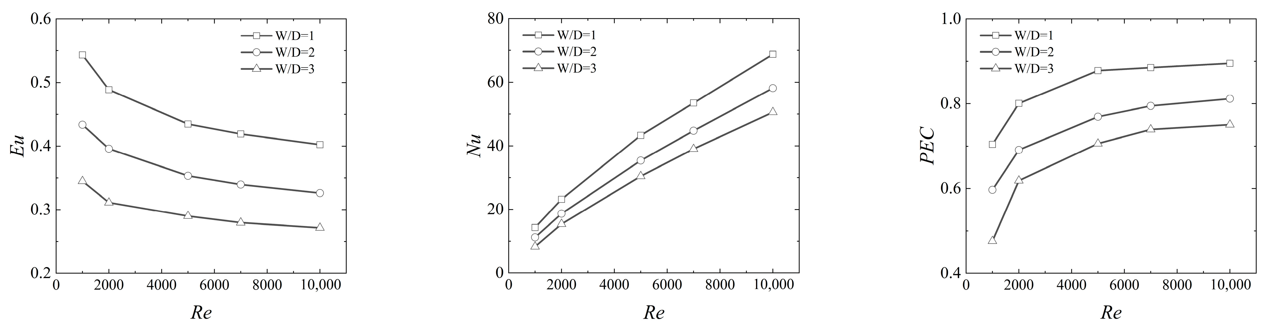
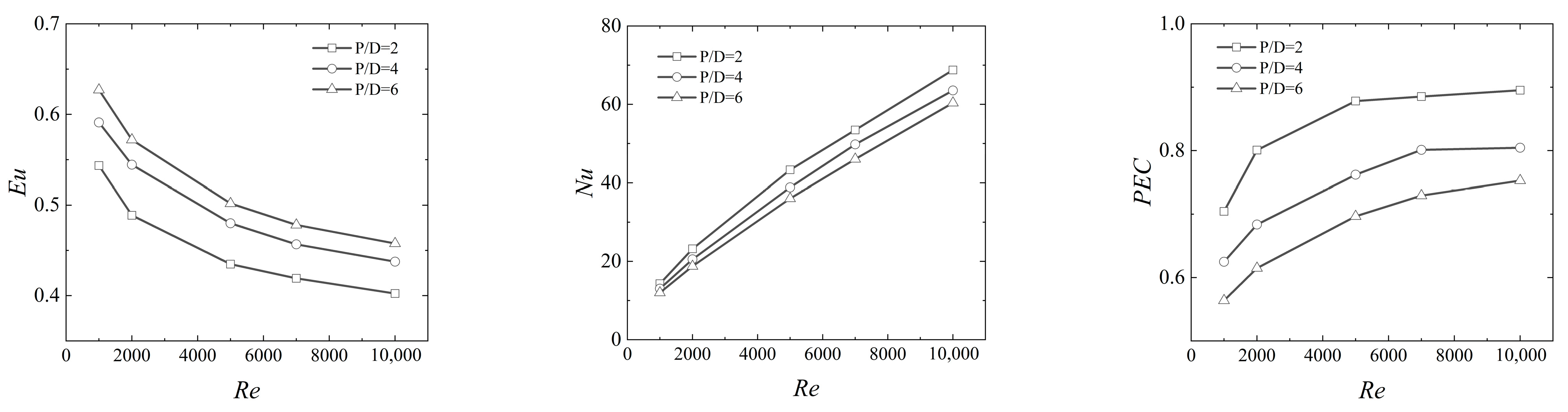
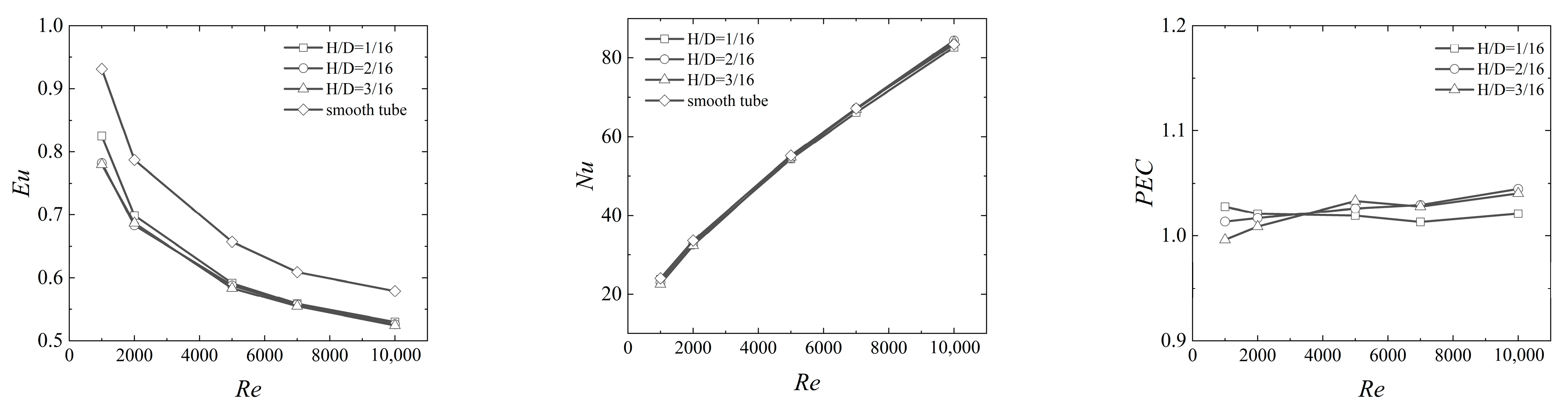
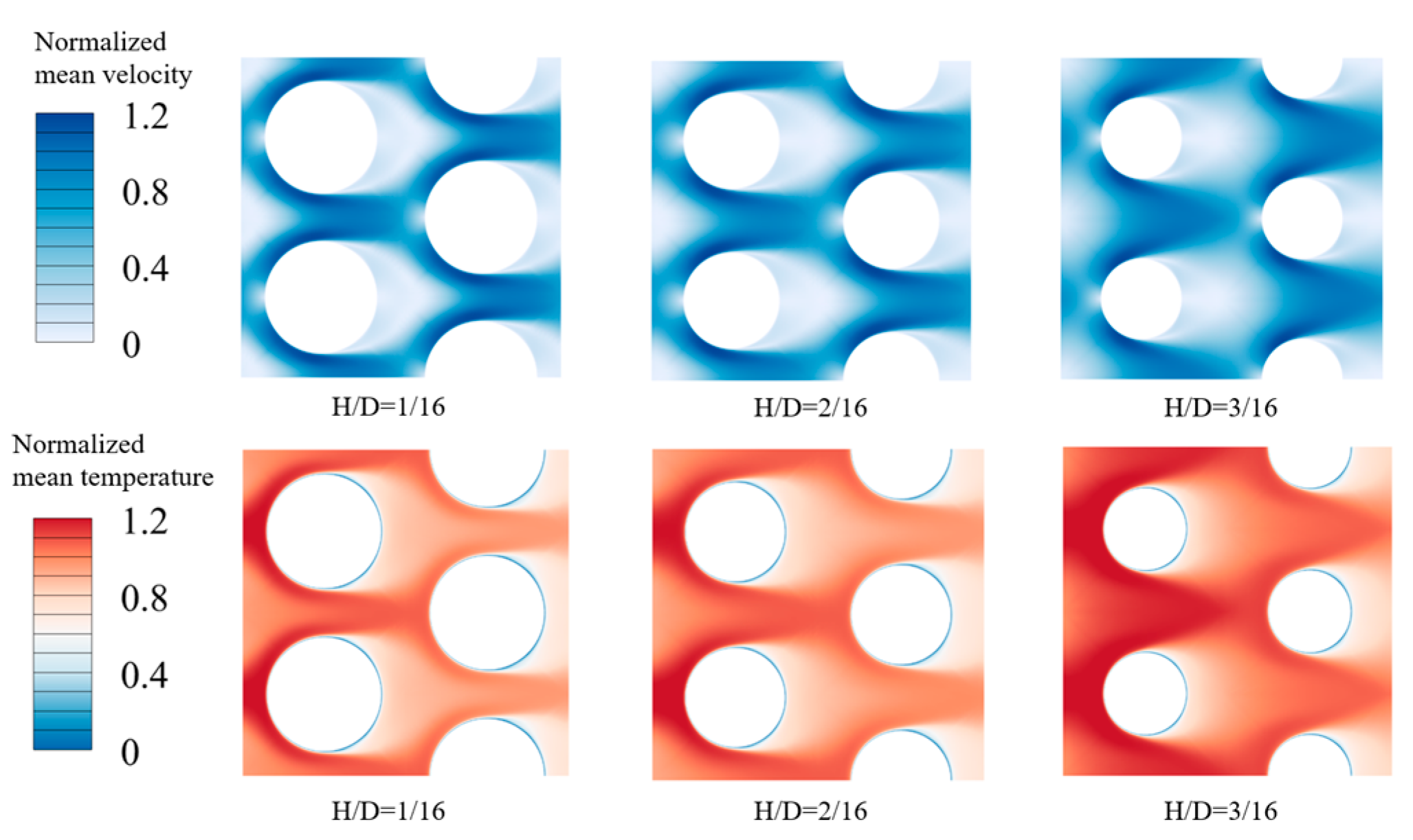
  • In an in-line configuration, PIC tubes demonstrate a significant decrease in both pressure drop and heat transfer performance as the corrugation height (H/D) and width (W/D) increase. The Euler number and Nusselt number for PIC tube banks can drop to half those of smooth circular tube banks. An increase in corrugation pitch (P/D) does elevate the pressure drop but diminishes the heat transfer coefficient. Overall, the thermal–hydraulic performance of PIC tube banks is inferior to that of SC tube banks.
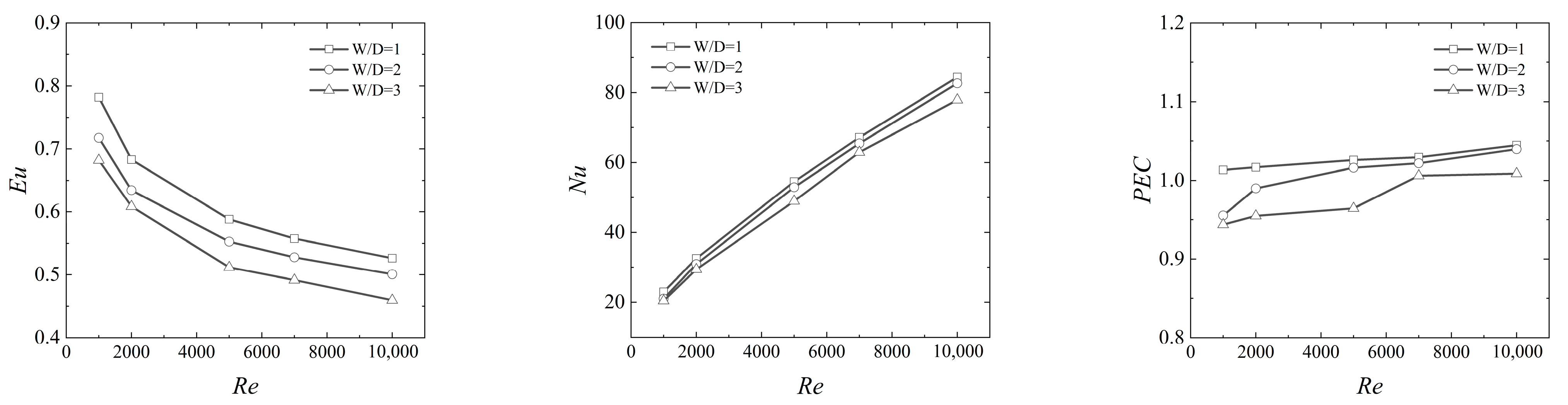
  • When comparing PIC tube banks with SC tube banks in a staggered arrangement, the global Nusselt number (Nu) remains relatively unchanged, but there is a notable reduction in the Euler number (Eu), leading to a favorable performance evaluation criterion (PEC). Changes in W/D and P/D affect the heat transfer coefficient and pressure drop, but their impact is less pronounced than in the in-line arrangement.
  • Our analysis indicates that for enhancing performance in heat exchangers using PIC tubes, a staggered arrangement of tube banks is preferable over an in-line arrangement.

Author Contributions

Conceptualization, Y.Z. and X.Z.; methodology, Y.Z., J.Z. and X.Z.; validation, Y.Z.; formal analysis, Y.Z. and L.Z.; investigation, Y.Z. and L.Z.; resources, J.Z. and X.Z.; data curation, Y.Z. and G.G.; writing—original draft preparation, Y.Z.; writing—review and editing, X.Z.; supervision, J.Z. All authors have read and agreed to the published version of the manuscript.

Funding

This research received no external funding.

Data Availability Statement

The original contributions presented in the study are included in the article, further inquiries can be directed to the corresponding author.

Conflicts of Interest

Author Lei Zhao was employed by the company Xinxiang Aviation Industry (Group) Co., Ltd. The remaining authors declare that the research was conducted in the absence of any commercial or financial relationships that could be construed as a potential conflict of interest.

Nomenclature

AThe area of the tube banks, m2
AminThe minimum cross-section area of the tube banks, m2
cpSpecific heat, J/kg·K
DTube diameter, m
EuEuler number
HCorrugation height, m
hHeat transfer coefficient, W/m2·K
LTTransverse spacing
LLLongitudinal spacing
NuNusselt number
PPeriodic length between corrugations, m
PECPerformance evaluation criteria
ΔpPressure drop per unit length, Pa/m
PrPrandtl number
qHeat flux, W/m2
qmMass flow rate, kg/s
ReReynolds number
STThe ratio of transverse spacing
SLThe ratio of longitudinal spacing
TTemperature, K
uVelocity, m/s
WCorrugation width, m
x,y,zCartesian coordinate
Greek symbols
μViscosity, Pa·s
ρFluid density, kg/m3
λThermal conductivity, W/m·K
Subscript
inInlet
outOutlet
wWall
abbreviation
PIC tubePeriodically inward-corrugated tube
SC tubeSmooth circular tube

References

  1. Kasim, K.; Muley, A.; Stoia, M.; Ladeinde, F. Advanced Heat Transfer Devices for Aerospace Applications. In Proceedings of the ASME International Mechanical Engineering Congress and Exposition, Tampa, FL, USA, 3–9 November 2017; American Society of Mechanical Engineers: New York, NY, USA, 2017; p. V008T010A027. [Google Scholar]
  2. Carozza, A. Heat Exchangers in the Aviation Engineering, Heat Exchangers—Advanced Features and Applications; IntechOpen: London, UK, 2017; pp. 149–166. [Google Scholar]
  3. Konstantinidis, E.; Castiglia, D.; Balabani, S. An experimental study of steady and pulsating cross-flow over a semi-staggered tube bundle. Proc. Inst. Mech. Eng. Part C J. Mech. Eng. Sci. 2005, 219, 283–298. [Google Scholar] [CrossRef]
  4. Grimison, E.D. Correlation and utilization of new data on flow resistance and heat transfer for cross flow of gases over tube banks. J. Fluids Eng. 1937, 59, 583–594. [Google Scholar] [CrossRef]
  5. Žkauskas, A. Heat transfer from tubes in crossflow. In Advances in Heat Transfer; Elsevier: Amsterdam, The Netherlands, 1987; pp. 87–159. [Google Scholar]
  6. Khan, W.; Culham, J.; Yovanovich, M. Convection heat transfer from tube banks in crossflow: Analytical approach. Int. J. Heat Mass Transf. 2006, 49, 4831–4838. [Google Scholar] [CrossRef]
  7. Wilson, A.S.; Bassiouny, M.K. Modeling of heat transfer for flow across tube banks. Chem. Eng. Process. Process Intensif. 2000, 39, 1–14. [Google Scholar] [CrossRef]
  8. El-Shaboury, A.M.F.; Ormiston, S.J. Analysis of laminar forced convection of air crossflow in in-line tube banks with nonsquare arrangements. Numer. Heat Transf. Part A Appl. 2005, 48, 99–126. [Google Scholar] [CrossRef]
  9. Zhang, L.-Z.; Ouyang, Y.-W.; Zhang, Z.-G.; Wang, S.-F. Oblique fluid flow and convective heat transfer across a tube bank under uniform wall heat flux boundary conditions. Int. J. Heat Mass Transf. 2015, 91, 1259–1272. [Google Scholar] [CrossRef]
  10. Mangrulkar, C.K.; Dhoble, A.S.; Chamoli, S.; Gupta, A.; Gawande, V.B. Recent advancement in heat transfer and fluid flow characteristics in cross flow heat exchangers. Renew. Sustain. Energy Rev. 2019, 113, 109220. [Google Scholar] [CrossRef]
  11. Bahaidarah, H.M.S.; Anand, N.K.; Chen, H.C. A Numerical Study of Fluid Flow and Heat Transfer over a Bank of Flat Tubes. Numer. Heat Transf. Part A Appl. 2005, 48, 359–385. [Google Scholar] [CrossRef]
  12. Horvat, A.; Mavko, B. Heat transfer conditions in flow across a bundle of cylindrical and ellipsoidal tubes. Numer. Heat Transf. Part A Appl. 2006, 49, 699–715. [Google Scholar] [CrossRef]
  13. Ibrahim, T.A.; Gomaa, A. Thermal performance criteria of elliptic tube bundle in crossflow. Int. J. Therm. Sci. 2009, 48, 2148–2158. [Google Scholar] [CrossRef]
  14. Terukazu, O.; Hideya, N.; Yukiyasu, T. Heat transfer and flow around an elliptic cylinder. Int. J. Heat Mass Transf. 1984, 27, 1771–1779. [Google Scholar] [CrossRef]
  15. Merker, G.; Hanke, H. Heat transfer and pressure drop on the shell-side of tube-banks having oval-shaped tubes. Int. J. Heat Mass Transf. 1986, 29, 1903–1909. [Google Scholar] [CrossRef]
  16. Tang, S.; Ding, L.; Sheng, R.; Zhao, K.; Zhang, D.; Shen, B. Parametric analysis on thermal-hydraulic characteristics in variable-direction twisted-oval tube bundle in cross-flow. Int. J. Therm. Sci. 2024, 197, 108761. [Google Scholar] [CrossRef]
  17. Li, X.; Zhu, D.; Yin, Y.; Liu, S.; Mo, X. Experimental study on heat transfer and pressure drop of twisted oval tube bundle in cross flow. Exp. Therm. Fluid Sci. 2018, 99, 251–258. [Google Scholar] [CrossRef]
  18. Sparrow, E.; Kang, S. Longitudinally-finned cross-flow tube banks and their heat transfer and pressure drop characteristics. Int. J. Heat Mass Transf. 1985, 28, 339–350. [Google Scholar] [CrossRef]
  19. Lemouedda, A.; Schmid, A.; Franz, E.; Breuer, M.; Delgado, A. Numerical investigations for the optimization of serrated finned-tube heat exchangers. Appl. Therm. Eng. 2011, 31, 1393–1401. [Google Scholar] [CrossRef]
  20. Zukauskas, A.; Ulinskas, R. Heat transfer in tube banks in crossflow. Adv. Heat Transf. 1988, 8, 93–160. [Google Scholar]
  21. Menter, F.R. Two-equation eddy-viscosity turbulence models for engineering applications. AIAA J. 1994, 32, 1598–1605. [Google Scholar] [CrossRef]
  22. Kim, T. Effect of longitudinal pitch on convective heat transfer in crossflow over in-line tube banks. Ann. Nucl. Energy 2013, 57, 209–215. [Google Scholar] [CrossRef]
  23. Jiang, H.; Niu, Y.; Yang, P.; Liu, Y. Effect of pulsation parameters on the spatial and temporal variation of flow and heat transfer characteristics in liquid metal cross flow the in-line tube bundle. Int. J. Heat Mass Transf. 2024, 219, 124871. [Google Scholar] [CrossRef]
  24. Incropera, F.P.; DeWitt, D.P.; Bergman, T.L.; Lavine, A.S. Fundamentals of Heat and Mass Transfer; Wiley: New York, NY, USA, 1996. [Google Scholar]
  25. Webb, R.L. Performance evaluation criteria for use of enhanced heat transfer surfaces in heat exchanger design. Int. J. Heat Mass Transf. 1981, 24, 715–726. [Google Scholar] [CrossRef]
  26. Yadav, N.; Gepner, S.W.; Szumbarski, J. Instability in a channel with grooves parallel to the flow. Phys. Fluids 2017, 29, 084104. [Google Scholar] [CrossRef]
  27. Harikrishnan, S.; Tiwari, S. Unsteady flow and heat transfer characteristics of primary and secondary corrugated. J. Heat Transf. 2020, 142, 031803. [Google Scholar] [CrossRef]
Figure 1. Schematic of tube banks with (a) in-line arrangement and (b) staggered arrangement. The red and blue boxes represent the smaller and the larger computational domains with 2 × 2 and 4 × 4 rows, respectively.
Energies 17 01641 g001
Figure 2. Schematic of PIC tubes.
Energies 17 01641 g002
Figure 3. Mesh for tube banks: (a) global grid layout for the in-line arrangement, with inset images highlighting grid refinement in the wall boundary layer; (b) close-up view of wall grids; (c) global grid layout for the staggered arrangement; (d) detailed view of wall grids.
Energies 17 01641 g003
Figure 4. Grid independence verification for (a) Eu and (b) Nu.
Energies 17 01641 g004
Figure 5. Comparison of the present simulation results with Zukauskas’s data and correlation [5] for smooth circular tube banks reveals good agreements in terms of the values of Eu and Nu.
Energies 17 01641 g005
Figure 6. The impacts of H/D on the PIC tube bank (W/D = 1; P/D = 2) performances in an in-line arrangement. The smooth tube bank is added as a baseline for comparative analysis.
Energies 17 01641 g006
Figure 7. Normalized velocity and temperature contours for in-line arrangement of different H/D at Re = 10,000 (W/D = 1; P/D = 2).
Energies 17 01641 g007
Figure 8. Isosurface of normalized velocity for u* = 1 at Re = 10,000 in an in-line arrangement.
Energies 17 01641 g008
Figure 9. The impacts of W/D on the PIC tube bank (H/D = 2/16, P/D = 2) performances in an in-line arrangement.
Energies 17 01641 g009
Figure 10. The non-uniform distribution of heat transfer coefficient on the PIC tubes with different values of P/D.
Energies 17 01641 g010
Figure 11. The impacts of P/D on the PIC tube bank (H/D = 2/16, W/D = 1) performances in an in-line arrangement.
Energies 17 01641 g011
Figure 12. The impacts of H/D on the PIC tube bank (W/D = 1; P/D = 2) performances in a staggered arrangement. The smooth tube bank is added as a baseline for comparative analysis.
Energies 17 01641 g012
Figure 13. The impacts of W/D on the PIC tube bank (H/D = 2/16; P/D = 2) performances in a staggered arrangement.
Energies 17 01641 g013
Figure 14. The impacts of P/D on the PIC tube bank (H/D = 2/16; W/D = 1) performances in a staggered arrangement.
Energies 17 01641 g014
Figure 15. Normalized velocity and temperature contours for staggered arrangement of different H/D at Re = 10,000 (W/D = 1; P/D = 2).
Energies 17 01641 g015
Figure 16. Comparative analysis of the total heat transfer rate and pressure drop against the mass flow rate: (a) heat transfer rate for in−line arrangement; (b) heat transfer rate for staggered arrangement; (c) pressure drop for in−line arrangement; (d) pressure drop for staggered arrangement.
Energies 17 01641 g016
Table 1. Dimensionless parameters of the PIC tube banks.
CaseH/DW/DP/D
11/1612
22/1612
33/1612
42/1622
52/1632
62/1614
72/1616
Table 2. Comparisons of Eu and Nu with different sized computational domains at Re = 10,000. (H/D = 2/16; W/D = 1; P/D = 2.)
Computed CasesEuNu
In-line arrangement 2 × 20.40268.78
In-line arrangement 4 × 40.40369.11
Staggered arrangement 2 × 20.52684.44
Staggered arrangement 4 × 40.52785.27
Disclaimer/Publisher’s Note: The statements, opinions and data contained in all publications are solely those of the individual author(s) and contributor(s) and not of MDPI and/or the editor(s). MDPI and/or the editor(s) disclaim responsibility for any injury to people or property resulting from any ideas, methods, instructions or products referred to in the content.

