Article

A Direct Chemical Approach to Mitigate Environment Lead Contamination in Perovskite Solar Cells

1
Information Materials and Intelligent Sensing Laboratory of Anhui Province, Anhui University, No. 111 Jiulong Road, Hefei 230601, China
2
Department of Environmental Studies, Middlebury College, 14 Old Chapel Road, 3245MC, Middlebury, VT 05753, USA
3
The Experimental High School Attached to Beijing Normal University, Beijing 100032, China
*
Author to whom correspondence should be addressed.
Energies 2024, 17(7), 1629; https://doi.org/10.3390/en17071629
Submission received: 9 January 2024 / Revised: 6 March 2024 / Accepted: 14 March 2024 / Published: 28 March 2024
(This article belongs to the Special Issue Organic and Hybrid Solar Cells for Efficient Solar Power Conversion)

Abstract

:
Current guidelines indicate that the lead levels in perovskite solar cells are sufficiently low, putting them on par with the safety of other lead-containing electronics. Yet, there remains ambiguity regarding the exact environmental impact of lead derived from perovskite. When this lead enters the soil, it has the potential to permeate plants and, subsequently, our food supply, at a rate that is a staggering ten times more than other lead contaminants from human-induced activities. Given this, it becomes vital to ensure that lead does not pollute our environment as we further adopt these technologies. In this study, we propose a novel method using polymer net bones to anchor the lead, which effectively reduces the risk of lead leaching due to rainfall. Perovskite Solar Cells (PSCs) integrated with this polymer net bone show improved operational efficiency and hold significant promise in curtailing lead leakage, reinforcing the ecological integrity of perovskite solutions. When enhanced with Polyvinyl Alcohol (PVA), these PSCs register a notable increase in Power Conversion Efficiency (PCE), scoring 24.7% as opposed to the 22.3% in PSCs devoid of PVA. Additionally, PVA-augmented PSCs outperform in stability when compared to their traditional counterparts.

1. Introduction

Metal halide perovskite solar cells (PSCs) are rapidly emerging as potential game-changers in the realm of sustainable energy solutions [1]. Their combination of affordability, exceptional performance, and streamlined processing positions them as a viable contender for reshaping the energy landscape in the upcoming years. Several treatments are performed on the perovskite film to increase the device performance and stability, including surface treatments [2,3,4], transporting layer optimization [5], electrode modification [6], perovskite crystallization optimization [7,8,9,10], etc.
However, a significant obstacle to their widespread adoption remains: many top-performing PSCs rely heavily on lead-based perovskites for light absorption [11,12,13].
The conundrum lies in lead’s inherent toxicity. When lead escapes from damaged PSCs, its adverse impact can reverberate through our environment and jeopardize human health. This not only raises concerns about the sustainability and longevity of PSCs but also questions their potential as an environmentally friendly power source [14,15,16,17]. Therefore, the development lead-free perovskite or avoiding lead leakage is important. Several research studies were conducted to enhance the stability and efficiency of lead-free perovskite solar cells [18,19,20,21,22,23].
Various strategies have been developed to mitigate lead leakage, particularly in scenarios where PSCs might be vulnerable, such as during severe weather events. Some of these solutions focus on creating barriers that can contain lead, but these often involve complicated adjustments to the original PSC design [24,25]. Such alterations can increase manufacturing complexity, potentially diminishing both performance and the feasibility of mass production. Concerns also linger about the longevity of these protective barriers; they might deteriorate when exposed to conditions like ion-rich rain, the UV rays of the sun, or even during routine maintenance [14,26,27,28]. Another tactic centers on integrating lead-absorbing materials directly within the perovskite layer [4,29,30]. While promising, there are concerns regarding the potential trade-offs in device efficiency based on the thickness or composition of this absorptive layer [31,32,33]. Moreover, many of the current solutions emphasize lead capture but pay inadequate attention to subsequent challenges posed by secondary lead contamination. This necessitates an evolved conversation around not just prevention but also lead recycling and complete management [34,35,36].
Furthermore, there is an undeniable urgency to address the stability of PSCs. While strides have been made in supporting the resilience of finished PSC products, it is equally critical to maintain the stability of perovskite materials—be it inks or films—throughout their entire production journey. The stability ensures the delivery of PSCs that are not only efficient and robust but also maintain consistent performance [4,37,38].
In our study, we unveil a groundbreaking double polyvinyl alcohol (PVA) strategy to fortify PSCs, resulting in devices that are more efficient, long-lasting, and reproducible. A noteworthy feature is the PVA’s capacity to envelop the perovskite grain seamlessly, drastically curtailing lead leakage. Our optimized PSCs showcase a remarkable Power Conversion Efficiency (PCE) of 24.7%, complemented by an extended operational life nearing 3000 h (~4 months). The embedded PVA matrix not only impedes lead escape but also amplifies the device’s efficiency and resilience. In essence, our approach paves the way for a sustainable, eco-conscious, and cost-effective paradigm in the fabrication of perovskite solar solutions that prioritize both performance and environmental integrity.

2. Materials and Methods

2.1. Materials

We sourced various chemical compounds from reputable suppliers to ensure quality. Sigma-Aldrich (Shanghai, China) provided chlorobenzene, dimethylformamide, dimethyl sulfoxide, 4-tert-butylpyridine, acetonitrile, Li-TFSI lead (II) bromide with a purity of 99.99%, and cesium iodide. From Greatcell Solar, we procured formamidine iodide and methylammonium bromide. The tin (IV) oxide, in a 15% water-based colloidal dispersion, came from Alfa Aesar (Shanghai, China). TCI supplied the lead (II) iodide, boasting a high purity of 99.998%. Lastly, Lumtec (Taiwan, China) was our chosen provider for spiro-OMeTAD.

2.2. Device Fabrication

To begin, we meticulously cleaned a 1.5 cm × 2 cm FTO substrate, starting with a soap wash, followed by a rinse using an acetone-isopropanol solution. After drying it in an oven, we exposed it to UV ozone for the final purification step. Subsequently, we prepared the substrate for conventional n-i-p structured PSCs. A slender film of SnO2 nanoparticles was established on this cleaned ITO substrate by employing a spin-coating technique. We used a 5 wt % SnO2 colloidal dispersion in water and set the spin speed at 5000 rpm. This layer was then annealed in a normal atmosphere at 150 °C for a half-hour.
For the perovskite layer, we formulated a mixed triple-cation (CsFAMA) precursor solution, specifically 1.2 M FA0.88MA0.04Cs0.08PbI3. This was achieved by dissolving the compound in a solvent blend of DMF and DMSO in a 4:1 volume ratio. On top of the perovskite layer, we applied the Spiro-OMeTAD HTL using a spin-coating method. The HTL solution comprised 80 mg/mL Spiro-OMeTAD in chlorobenzene, 29 μL of tBP, and 17.5 μL of Li-TFSI (concentration of 520 mg/mL in acetonitrile).
Concluding the device assembly, we laid down an 80-nm-thick gold electrode. This was executed via thermal evaporation, with the assistance of a shadow mask to create distinct electrode patterns. For protection and enhanced stability, the constructed devices were encapsulated within a nitrogen-filled glovebox, with the edges meticulously sealed using epoxy resin, and capped with a protective glass cover.

2.3. Lead Leakage Tests Procedure

Every piece of equipment, from the glassware to the funnels designated for the lead (Pb) leakage tests, was meticulously cleaned using deionized (DI) water. Notably, the DI water chosen for this process contained such a minuscule Pb concentration that it was below the detection capability of our ICP-MS instrument.
For the actual tests, we deliberately damaged the perovskite solar cell using an ice ball with a 2-inch diameter. Once damaged, these modules were carefully placed on a funnel angled at roughly 30°. We then introduced an acidic solution, a blend of HNO3 and DI water with a pH of 4.2, directly onto the damaged areas of the modules. Utilizing a dropping funnel, this solution was dispensed at a steady rate of 5 mL every hour, lasting for a complete hour.
Post-test, we collected the runoff water, which might have been tainted with Pb, into centrifuge tubes for further analysis. Leveraging the capabilities of the ICP-MS Nexion 300D instrument, we analyzed the samples. Before any analysis was initiated, we charted a reference curve by assessing standard solutions, crafted by merging a standard Pb solution with a 2% mixture of HNO3 and DI water.

2.4. Characterizations

Scanning Electron Microscope (SEM) images were acquired using a Hitachi SU8010. Photoluminescence (PL) assessments were performed with the Edinburgh Instrument FLS980. The J-V characteristics of the PSCs, steady-state current, and power output measurements were documented using a Keithley 2400 source meter, under the AM 1.5 G illumination setting (100 mW/cm2), courtesy of the SS-F5-3A solar simulator from Enli Technology, Co., Ltd. (Taiwan, China). The measurement took place in ambient conditions and at room temperature. To ensure accurate light intensity measurements, we used the standard Si solar cell (SRC-00036, Enli Technology Co., Ltd.) for calibration. For obtaining EQE spectra, we used the QE-R3011 system, designed specifically for solar cell spectral response measurements by Enli Technology, Co., Ltd. The light’s intensity at varying wavelengths was standardized using the Si solar cell (SRC-00036). Lastly, to study the crystalline structure, we utilized the Rigaku SmartLab X-ray diffractometer, employing Cu Kα radiation, with increments of 0.01° in a θ–2θ scanning mode ranging from 10° to 60°. Since the range of 60–90° lacks distinctive features, we focused on collecting the X-ray Diffraction (XRD) peak between 10° and 60°. Steady-state PL spectra were obtained using a 488 nm laser as an excitation source.

2.5. Stability Measurement

The stability measurement of the perovskite solar cell is conducted under 1 Sun illumination and 75 °C. The structure of a perovskite solar cell is FTO/SnO2/Perovskite/PTAA/Au. Here, PTAA (Poly(bis(4-phenyl)(2,4,6-trimethylphenyl)amine)) is applied as the hole transporting layer for the concern of thermal stability. The PTAA layer was deposited by spin coating the PTAA solution (10 mg/mL in toluene) with 2 µL tBP and 2 µL Li-TFSI solution (520 mg/mL in acetonitrile) onto the perovskite film at 4000 rpm for 30 s. The device was finished by thermal evaporating 80 nm Au as back contact. The perovskite solar cell is then encapsulated with epoxy glue.

3. Results and Discussion

In this study, we present a novel approach aimed at addressing the environmental concerns associated with lead leakage from PSCs. As illustrated in Figure 1a, the PSCs adopt a conventional structure, delineated as FTO/SnO2/Perovskite/Spiro-MeOTAD/Au. The specific perovskite composition we utilized is FA0.88MA0.04Cs0.08PbI3, crafted using CB (Chlorobenzene) as the antisolvent. Figure 1b offers a visual of the chemical composition of PVA.
Our method incorporates a dual treatment strategy, where we added 1% of PVA into the perovskite precursor and an additional 2% into the CB. This has a two-fold benefit: the PVA in the precursor effectively coordinates with Pb, and the PVA in the CB assists in creating a fine PVA layer within the perovskite grain. This combined application is intended to fashion a protective PVA ‘cage’ around the perovskite, thereby preventing lead seepage, especially under rainy conditions. A visual representation of the PVA-encased perovskite structure can be viewed in Figure 1c.
Figure 2 presents the SEM images of the perovskite films, both with and without PVA. In the control film’s SEM image, distinct grain boundaries are evident. The control film boasts an average grain size of approximately 500 nm. However, when treated with PVA, there is a significant increase in the perovskite grain size, measuring around 2 µm. This increase in grain size can be attributed to PVA’s ability to coordinate with the lead, promoting grain growth. A conspicuous thin PVA layer can be observed encapsulating the perovskite grain. The grain boundaries of the perovskite appear to be infused with PVA. Notably, the surface of the perovskite displays white spots, indicative of the presence of PVA.
To study deeper into the effects of PVA modification on photovoltaic performance, we constructed PSCs featuring a device architecture of FTO/SnO2/Perovskite/Spiro-MeOTAD/Au, as illustrated in Figure 1a. Figure 3 showcases a cross-sectional SEM-EDX analysis of the PVA-based device, highlighting the distinct layers and elemental mapping for Sn, O, N, and Au. Figure 3a provides a detailed cross-section view of the PVA-based perovskite device. Figure 3b–e illustrates the elemental mappings for Sn, O, N, and Au, respectively. The analysis reveals that Sn primarily resides at the device’s base, a contribution from the FTO and SnO2 layers, as demonstrated in Figure 3b. The O element exhibits a weak but uniform distribution across the perovskite layer, attributed to the PVA integration within this layer, detailed in Figure 3c. The distribution of the N element is also uniform across the perovskite layer, originating from the FAI’s N component, shown in Figure 3d. Lastly, the Au element is predominantly found at the device’s top, aligning with the top Au electrode, as observed in Figure 3e.
In the process of optimizing PSCs with PVA, we initially varied the concentration of PVA in the perovskite precursor between 0.5 wt% and 1 wt%. Incorporating PVA into the perovskite precursor significantly enhanced the open-circuit voltage (Voc), increasing it from 1.099 V to 1.139 V, as illustrated in Figure 4 and Table 1. However, introducing higher amounts of PVA resulted in a reduced fill factor (FF) for the PSCs. The optimal PVA concentration was determined to be 1 wt%, which produced a (PCE) of 23.03%, a Voc of 1.139 V, an FF of 0.817, and a short-circuit current density (Jsc) of 24.7 mA/cm2. Consequently, this 1 wt% concentration was used in the subsequent optimization of PVA which is added in antisolvent. We tested three different PVA concentrations in the antisolvent, ranging from 1 wt% to 3 wt%. The optimum performance was achieved with 1 wt% PVA in the precursor and 2 wt% PVA in the antisolvent, yielding a PCE of 24.78%, a Voc of 1.189 V, an FF of 0.823, and a Jsc of 25.2 mA/cm2 (Table 2).
The J–V characteristics for PSCs, both with and without the PVA modification, are showcased in Figure 5a. Pertinent photovoltaic parameters derived from these characteristics are detailed in Table 1. Our optimization process incorporated 1 wt% PVA in the perovskite precursor and an additional 2% in the antisolvent CB. Remarkably, the PCE of the PVA-enhanced device peaked at 24.7%, surpassing the control device’s 22.8% (see Figure 5b and Table 1). The PVA-infused PSC recorded a Jsc of 25.3 mA/cm2, Voc of 1.19 V, and an FF of 0.82, while the control device posted figures of Jsc = 25.1 mA/cm2, Voc = 1.1 V, and FF = 0.81. The elevated Voc in PVA-integrated PSCs can be attributed to the perovskite film’s passivation by PVA. Figure 5b presents the external quantum efficiency (EQE) measurements for PSCs with and without PVA modification. Analysis of the EQE spectrum reveals that the peak efficiency for PSCs without PVA reaches approximately 97%, while PSCs modified with PVA exhibit a peak efficiency of about 96%. Notably, in the wavelength range of 500 nm to 700 nm, the EQE for PSCs incorporating PVA surpasses that of PSCs without PVA. The integrated current density, derived from the EQE spectrum, amounts to 23.97% for PSCs with PVA and 23.86% for those without PVA.
Figure 5c displays the XRD patterns of the perovskite films with and without PVA. The diffraction peaks observed around 2θ values of 14.20°, 20.08°, 23.51°, 24.55°, 28.58°, 35.1°, 40.8°, and 43.0° correspond to the (100), (112), (211), (202), (200), (310), (312), (224), and (314) planes of the tetragonal perovskite structure, respectively [39,40,41]. The diffraction peaks indicate high crystallinity and orientation of the perovskite. From Figure 5c, it is evident that the PSCs incorporating PVA exhibit more pronounced peaks than those without PVA. This distinction can be attributed to the PVA treatment, which significantly bolsters the crystallinity and overall quality of the perovskite film. This enhanced crystallinity likely plays a pivotal role in the improved Voc of the perovskite film.
Figure 5d presents the absorption spectra of perovskite films with and without PVA. The absorption profiles of both films are largely similar, with only slight variations. Notably, the absorption edge of the film integrated with PVA shows a slight shift towards longer wavelengths. This suggests that while the presence of PVA does not dramatically alter the absorption intensity of the perovskite film, it does subtly influence the film’s bandgap.
Turning to Figure 5e, the normalized PL spectra of the two films are presented. Remarkably, the PL intensity of the PVA-incorporated film is double that of the film without PVA. Furthermore, the PL peak for the PVA-integrated film stands at approximately 802 nm, while the counterpart without PVA peaks around 800 nm. Based on these observations, the computed bandgap for FA0.88MA0.04Cs0.08PbI3 is determined to be 1.55 eV. The amplified PL intensity of the PVA-treated perovskite film can likely be ascribed to its enhanced crystallinity and diminished trap states [29,42].
Time-resolved photoluminescence (TRPL) analysis is an insightful technique employed to discern the dynamics of photo-induced charge carriers within materials [43,44]. For our study, this method was instrumental in understanding the effects of PVA passivation on perovskite films, the results of which are depicted in Figure 5f. For this investigation, sample preparation was executed meticulously on glass substrates, following a distinct structure, specifically glass/perovskite.
To extract meaningful information from the PL decay curves and to understand the kinetics of the decay processes, we adopted a bi-exponential decay function [9,16,45,46,47,48,49,50]. This mathematical representation is expressed as:
I t = A 1 exp t τ 1 + A 2 exp ( t τ 2 )
Here:
τ 1 is the smaller time constant indicative of bimolecular recombination.
τ 2 is the larger time constant representing the charge carrier lifetime within the perovskite film.
A 1 and A 2 denote the respective PL decay amplitudes of these processes.
A meticulous analysis of these decay constants offers insights into the intricate recombination dynamics at play within the perovskite material. In Table 3, the extracted PL decay times and amplitudes from our fitting procedure are tabulated. An intriguing observation was the PL decay time of the perovskite film integrated with PVA, which stood at 1757 ns. This contrasts with the decay time of 1600 ns for the film devoid of PVA.
This reduction in PL decay time for the perovskite film fabricated without PVA is indicative of its faster recombination kinetics. Essentially, this phenomenon suggests that PVA incorporation acts as an effective passivating agent. Its presence in the perovskite matrix aids in mitigating trap states, consequently leading to a suppression of unwanted charge recombination. Such insights are not only pivotal for optimizing device performance but also underscore the significance of materials engineering in advancing photovoltaic technology.
The electronic structure of the control film and film with PVA are investigated via ultraviolet photoelectron emission spectra (UPS), shown in Figure 6. The highest occupied VB level, CB level, and work function (WF) are calculated and shown in Figure 6. It is noted that the CB level for perovskite film without PVA is −4.2 eV and film with PVA is −4.25 eV. For the VB level, the film without PVA is −5.75 eV, and the film with PVA is −5.8 eV. The PVA treatment has little influence on the film’s electronic structure.
We subsequently assessed the extent of Pb leakage from damaged PSCs having identical device architectures as depicted in Figure 1a. A direct comparison was made between Pb leakages from the damaged PSCs (encompassing a total area of 6 cm2 across ten devices) with and without the presence of a PVA network. The entire set of devices was merely sealed using a cover glass, with the edges sealed by epoxy. The schematical illustration for the lead leakage test procedure is shown in Figure 7 (detail can be found in the experiment part). The perovskite solar cell is damaged by an ice ball with a 2-inch diameter. Once damaged, these modules were carefully placed on a funnel angled at roughly 30°. We then introduced an acidic solution, a blend of HNO3 and DI water with a pH of 4.2, directly onto the damaged areas of the modules. Utilizing a dropping funnel, this solution was dispensed at a steady rate of 5 mL every hour, lasting for a complete hour. Post-test, we collected the runoff water, which might have been tainted with Pb, into centrifuge tubes for further analysis. Leveraging the capabilities of the ICP-MS Nexion 300D instrument, we analyzed the samples. Before any analysis was initiated, we charted a reference curve by assessing standard solutions, crafted by merging a standard Pb solution with a 2% mixture of HNO3 and DI water. The Pb concentration in the potentially contaminated water was continuously monitored using inductively coupled plasma mass spectrometry (ICP-MS).
Upon being subjected to water immersion and agitation for a span of 10 min, the Pb content in the film without PVA was observed to be 0.3 ppm. This was considerably higher when compared to the film incorporated with PVA, which registered a minimal Pb concentration of 0.005 ppm (as shown in Figure 8). Prolonging the water exposure time beyond 2 h did not substantially elevate the Pb concentration for the PVA-integrated film. This observation suggests that the majority of the soluble Pb ions might have already seeped out in the initial stages, while the residual Pb ions remained entrapped within the devices fortified with PVA. As a result, these ions were unable to leach into the environment, even under harsh weather scenarios. Contrarily, the Pb concentration in the device devoid of PVA steadily rose with prolonged exposure, hitting its peak concentration over time.
Our results go beyond just presenting a mere Pb-absorbing material that chemically sequesters Pb ions. The cross-linking PVA network we have implemented showcases robust chemical adsorption due to diverse interactions. Concurrently, it provides a physical barrier, capturing the Pb ions within the interstices of the PVA’s intricate lattice. This dual-action mechanism stands out as a commendable approach to mitigate Pb leakage effectively.
With the incorporation of PVA, the contact angles of water on top of perovskite films also vary, as shown in Figure 9. The contact angle of water on the control film is 53° and the contact angle of water on the film with PVA is 64°. The higher contact angle of water on film with PVA is due to the perovskite coverage by PVA.
Device longevity and resilience are paramount considerations for the industrial adoption of PSCs. Yet, there exists a notable lack of stability data, particularly for planar configurations, which can be considered a significant roadblock.
Addressing this gap, we embarked on a comprehensive study assessing the durability of perovskite films, comparing those with and without the PVA modification. Specifically, we evaluated the encapsulated FA0.88MA0.04Cs0.08PbI3 composition PSCs both with and without this polymer enhancement. This entailed subjecting the samples to aging under continuous 1 sun illumination and 75 °C for an extended period of 3000 h.
Figure 10 vividly illustrates the outcomes. The PSCs devoid of PVA experienced a precipitous decline in performance. Within just 1000 h, there was a staggering 90% drop in their PCE. On the flip side, PSCs bolstered with PVA portrayed remarkable resilience. Intriguingly, there was an initial surge in PCE during the first 250 h, a phenomenon we attribute to the ‘light soaking effect’ inherent to PSCs. Beyond this timeframe, a rapid decline in PCE often likened to a “burn-in” effect, was evident. Then the efficiency is gradually dropped for the control device. However, the PCE of the device with PVA exhibited impressive stability, clocking in at 90% even after 3000 h of relentless testing. Thus, the additive of PVA in the perovskite can greatly increase the stability of the perovskite solar cell.
These data accentuates the pivotal role that device architecture plays, not just in influencing performance, but critically in determining the long-term stability of PSCs. The enhancements via PVA integration have multifaceted benefits. Beyond its pivotal role in mitigating Pb leakage, PVA-modified PSCs also exhibit enhanced stability. We hypothesize that the commendable durability is anchored in the role of PVA serving as a robust shield against a plethora of external degradation threats, including moisture, atmospheric vapors, and diffusive metal electrodes. Furthermore, one of the challenges for planar PSCs lies in achieving a flawless, compact perovskite absorber layer. This is not only essential for optimal performance but also plays a critical protective role against aforementioned external degradative forces. The presence of PVA, in this case, significantly aids in realizing this objective.

4. Conclusions

In closing, we have pioneered a novel approach by seamlessly integrating the cross-linking prowess of PVA with perovskites. This union not only elevates device efficiency and promises reproducibility but also offers a robust defense against the Pb leakage, thus considerably dampening its toxicity concerns. Impressively, with the incorporation of PVA, perovskite’s tendency for Pb leakage dwindles, nearing negligible levels. Additionally, the amalgamation with PVA remarkably reinforces the overall robustness, endurance, and impact resistance of the resulting PSCs, ensuring they withstand even the harshest environmental adversities.
Our inventive double PVA strategy breathes new life into PSCs, producing devices that shine in terms of efficiency, durability, and consistent performance. A salient attribute here is PVA’s innate ability to enmesh around the perovskite grain, drastically minimizing potential lead escape routes. Our optimized PSCs, riding on these enhancements, boast a PCE of 24.7%, paired with an operational lifespan extending close to 3000 h.
This revolutionary endeavor directly confronts and mitigates the primary challenges that have historically overshadowed perovskite photovoltaics: their inherent instability, varied reproducibility, the looming threat of lead leakage, and the concomitant toxicity concerns. As we look ahead, we envision this breakthrough serving as the impetus for rapid commercialization and pragmatic utilization of perovskite solar solutions and associated optoelectronic devices, setting them on a path of sustainable and eco-conscious development.

Author Contributions

Conceptualization, B.L. and Z.C.; Device fabrication, B.L. and Z.J. Characterization, B.L. and Z.J.; Writing—original draft preparation, B.L.; Writing—review and editing, B.L. and Z.C.; Supervision, Z.C.; Project administration, Z.C.; Funding acquisition, Z.C. All authors have read and agreed to the published version of the manuscript.

Funding

This research received no external funding.

Data Availability Statement

The original contributions presented in the study are included in the article, further inquiries can be directed to the corresponding author.

Conflicts of Interest

The authors declare no conflict of interest.

References

  1. Green, M.A.; Dunlop, E.D.; Hohl-Ebinger, J.; Yoshita, M.; Kopidakis, N.; Bothe, K.; Hinken, D.; Rauer, M.; Hao, X. Solar cell efficiency tables (Version 60). Prog. Photovolt. Res. Appl. 2022, 30, 687–701. [Google Scholar] [CrossRef]
  2. Huo, X.; Sun, W.; Wang, K.; Liu, W.; Yin, R.; Sun, Y.; Gao, Y.; You, T.; Yin, P. Preparation of High-Efficiency (>14%) HTL-Free Carbon-Based All-Inorganic Perovskite Solar Cells by Passivation with PABr Derivatives. ACS Appl. Mater. Interfaces 2023, 15, 9382–9391. [Google Scholar] [CrossRef]
  3. Zhang, H.; Yu, W.; Guo, J.; Xu, C.; Ren, Z.; Liu, K.; Yang, G.; Qin, M.; Huang, J.; Chen, Z. Excess PbI2 Management via Multimode Supramolecular Complex Engineering Enables High-Performance Perovskite Solar Cells. Adv. Energy Mater. 2022, 12, 2201663. [Google Scholar] [CrossRef]
  4. Yang, G.; Ren, Z.; Liu, K.; Qin, M.; Deng, W.; Zhang, H.; Wang, H.; Liang, J.; Ye, F.; Liang, Q.; et al. Stable and low-photovoltage-loss perovskite solar cells by multifunctional passivation. Nat. Photonics 2021, 15, 681–689. [Google Scholar] [CrossRef]
  5. Bhandari, S.; Roy, A.; Mallick, T.K.; Sundaram, S. Impact of different light induced effect on organic hole-transporting layer in perovskite solar cells. Mater. Lett. 2020, 268, 127568. [Google Scholar] [CrossRef]
  6. Bogachuk, D.; Tsuji, R.; Martineau, D.; Narbey, S.; Herterich, J.P.; Wagner, L.; Suginuma, K.; Ito, S.; Hinsch, A. Comparison of highly conductive natural and synthetic graphites for electrodes in perovskite solar cells. Carbon 2021, 178, 10–18. [Google Scholar] [CrossRef]
  7. Zhang, H.; Ren, Z.; Liu, K.; Qin, M.; Wu, Z.; Shen, D.; Zhang, Y.; Chandran, H.T.; Hao, J.; Lee, C.S. Controllable Heterogenous Seeding-Induced Crystallization for High-Efficiency FAPbI3-Based Perovskite Solar Cells Over 24%. Adv. Mater. 2022, 34, 2204366. [Google Scholar] [CrossRef] [PubMed]
  8. Zhang, H.; Qin, M.; Chen, Z.; Yu, W.; Ren, Z.; Liu, K.; Huang, J.; Zhang, Y.; Liang, Q.; Chandran, H.T. Bottom-Up Quasi-Epitaxial Growth of Hybrid Perovskite from Solution Process—Achieving High-Efficiency Solar Cells via Template-Guided Crystallization. Adv. Mater. 2021, 33, 2100009. [Google Scholar] [CrossRef]
  9. Qin, M.; Xue, H.; Zhang, H.; Hu, H.; Liu, K.; Li, Y.; Qin, Z.; Ma, J.; Zhu, H.; Yan, K. Precise Control of Perovskite Crystallization Kinetics via Sequential A-Site Doping. Adv. Mater. 2020, 32, 2004630. [Google Scholar] [CrossRef]
  10. Zhang, H.; Chen, Z.; Qin, M.; Ren, Z.; Liu, K.; Huang, J.; Shen, D.; Wu, Z.; Zhang, Y.; Hao, J. Multifunctional Crosslinking-Enabled Strain-Regulating Crystallization for Stable, Efficient α-FAPbI3-Based Perovskite Solar Cells. Adv. Mater. 2021, 33, 2008487. [Google Scholar] [CrossRef]
  11. Chen, B.; Rudd, P.N.; Yang, S.; Yuan, Y.; Huang, J. Imperfections and their passivation in halide perovskite solar cells. Chem. Soc. Rev. 2019, 48, 3842–3867. [Google Scholar] [CrossRef]
  12. Huang, J.; Yuan, Y.; Shao, Y.; Yan, Y. Understanding the physical properties of hybrid perovskites for photovoltaic applications. Nat. Rev. Mater. 2017, 2, 1–19. [Google Scholar] [CrossRef]
  13. Jordan, D.C.; Kurtz, S.R. Photovoltaic degradation rates—An analytical review. Prog. Photovolt. Res. Appl. 2013, 21, 12–29. [Google Scholar] [CrossRef]
  14. Gao, Y.; Hu, Y.; Yao, C.; Zhang, S. Recent Advances in Lead-Safe Perovskite Solar Cells. Adv. Funct. Mater. 2022, 32, 2208225. [Google Scholar] [CrossRef]
  15. Wang, X.; Dong, B.; Feng, M.; Xue, D.-J.; Wang, S.-M. Sustainable management of lead in perovskite solar cells. J. Mater. Chem. A 2022, 10, 15861–15864. [Google Scholar] [CrossRef]
  16. Li, X.; Zhang, F.; Wang, J.; Tong, J.; Xu, T.; Zhu, K. On-device lead-absorbing tapes for sustainable perovskite solar cells. Nat. Sustain. 2021, 4, 1038–1041. [Google Scholar] [CrossRef]
  17. Park, S.Y.; Park, J.-S.; Kim, B.J.; Lee, H.; Walsh, A.; Zhu, K.; Kim, D.H.; Jung, H.S. Sustainable lead management in halide perovskite solar cells. Nat. Sustain. 2020, 3, 1044–1051. [Google Scholar] [CrossRef]
  18. Piñón Reyes, A.C.; Ambrosio Lázaro, R.C.; Monfil Leyva, K.; Luna López, J.A.; Flores Méndez, J.; Heredia Jiménez, A.H.; Muñoz Zurita, A.L.; Severiano Carrillo, F.; Ojeda Durán, E. Study of a lead-free perovskite solar cell using CZTS as HTL to achieve a 20% PCE by SCAPS-1D simulation. Micromachines 2021, 12, 1508. [Google Scholar] [CrossRef]
  19. Rabhi, S.; Benzouid, H.; Slami, A.; Dadda, K. Modeling and Numerical Simulation of a CH3NH3SnI3 Perovskite Solar Cell Using the SCAPS1-D Simulator. Eng. Proc. 2023, 56, 97. [Google Scholar] [CrossRef]
  20. Ghosh, S.; Yasmin, S.; Ferdous, J.; Saha, B.B. Numerical Analysis of a CZTS Solar Cell with MoS2 as a Buffer Layer and Graphene as a Transparent Conducting Oxide Layer for Enhanced Cell Performance. Micromachines 2022, 13, 1249. [Google Scholar] [CrossRef]
  21. Yang, S.; Fu, W.; Zhang, Z.; Chen, H.; Li, C.-Z. Recent advances in perovskite solar cells: Efficiency, stability and lead-free perovskite. J. Mater. Chem. A 2017, 5, 11462–11482. [Google Scholar] [CrossRef]
  22. Giustino, F.; Snaith, H.J. Toward lead-free perovskite solar cells. ACS Energy Lett. 2016, 1, 1233–1240. [Google Scholar] [CrossRef]
  23. Zheng, W.; Sun, R.; Liu, Y.; Wang, X.; Liu, N.; Ji, Y.; Wang, L.; Liu, H.; Zhang, Y. Excitation management of lead-free perovskite nanocrystals through doping. ACS Appl. Mater. Interfaces 2021, 13, 6404–6410. [Google Scholar] [CrossRef] [PubMed]
  24. Liang, Y.; Song, P.; Tian, H.; Tian, C.; Tian, W.; Nan, Z.; Cai, Y.; Yang, P.; Sun, C.; Chen, J. Lead leakage preventable fullerene-porphyrin dyad for efficient and stable perovskite solar cells. Adv. Funct. Mater. 2022, 32, 2110139. [Google Scholar] [CrossRef]
  25. Luo, H.; Li, P.; Ma, J.; Han, L.; Zhang, Y.; Song, Y. Sustainable Pb management in perovskite solar cells toward eco-friendly development. Adv. Energy Mater. 2022, 12, 2201242. [Google Scholar] [CrossRef]
  26. Niu, T.; Lu, J.; Tang, M.-C.; Barrit, D.; Smilgies, D.-M.; Yang, Z.; Li, J.; Fan, Y.; Luo, T.; McCulloch, I. High performance ambient-air-stable FAPbI 3 perovskite solar cells with molecule-passivated Ruddlesden–Popper/3D heterostructured film. Energy Environ. Sci. 2018, 11, 3358–3366. [Google Scholar] [CrossRef]
  27. Xiao, X.; Wang, M.; Chen, S.; Zhang, Y.; Gu, H.; Deng, Y.; Yang, G.; Fei, C.; Chen, B.; Lin, Y. Lead-adsorbing ionogel-based encapsulation for impact-resistant, stable, and lead-safe perovskite modules. Sci. Adv. 2021, 7, eabi8249. [Google Scholar] [CrossRef] [PubMed]
  28. Liang, J.; Wang, C.; Wang, Y.; Xu, Z.; Lu, Z.; Ma, Y.; Zhu, H.; Hu, Y.; Xiao, C.; Yi, X. All-inorganic perovskite solar cells. J. Am. Chem. Soc. 2016, 138, 15829–15832. [Google Scholar] [CrossRef] [PubMed]
  29. Li, Z.; Wu, X.; Wu, S.; Gao, D.; Dong, H.; Huang, F.; Hu, X.; Jen, A.K.-Y.; Zhu, Z. An effective and economical encapsulation method for trapping lead leakage in rigid and flexible perovskite photovoltaics. Nano Energy 2022, 93, 106853. [Google Scholar] [CrossRef]
  30. Chao, L.; Niu, T.; Xia, Y.; Chen, Y.; Huang, W. Ionic Liquid for Perovskite Solar Cells: An Emerging Solvent Engineering Technology. Acc. Mater. Res. 2021, 2, 1059–1070. [Google Scholar] [CrossRef]
  31. Wu, P.; Wang, S.; Li, X.; Zhang, F. Beyond efficiency fever: Preventing lead leakage for perovskite solar cells. Matter 2022, 5, 1137–1161. [Google Scholar] [CrossRef]
  32. Rong, Y.; Hu, Y.; Mei, A.; Tan, H.; Saidaminov, M.I.; Seok, S.I.; McGehee, M.D.; Sargent, E.H.; Han, H. Challenges for commercializing perovskite solar cells. Science 2018, 361, eaat8235. [Google Scholar] [CrossRef] [PubMed]
  33. Zhang, H.; Liang, C.; Sun, M.; Sun, F.; Ji, C.; Wan, X.; Li, D.; You, F.; He, Z. Controlled Crystallization of CsRb-Based Multi-Cation Perovskite Using a Blended Sequential Process for High-Performance Solar Cells. Solar RRL 2021, 5, 2100050. [Google Scholar] [CrossRef]
  34. Schmidt, F.; Amrein, M.; Hedwig, S.; Kober-Czerny, M.; Paracchino, A.; Holappa, V.; Suhonen, R.; Schäffer, A.; Constable, E.C.; Snaith, H.J. Organic solvent free PbI2 recycling from perovskite solar cells using hot water. J. Hazard. Mater. 2023, 447, 130829. [Google Scholar] [CrossRef] [PubMed]
  35. Chen, B.; Fei, C.; Chen, S.; Gu, H.; Xiao, X.; Huang, J. Recycling lead and transparent conductors from perovskite solar modules. Nat. Commun. 2021, 12, 5859. [Google Scholar] [CrossRef] [PubMed]
  36. Feng, X.; Guo, Q.; Xiu, J.; Ying, Z.; Ng, K.W.; Huang, L.; Wang, S.; Pan, H.; Tang, Z.; He, Z. Close-loop recycling of perovskite solar cells through dissolution-recrystallization of perovskite by butylamine. Cell Rep. Phys. Sci. 2021, 2, 2. [Google Scholar] [CrossRef]
  37. Dewi, H.A.; Li, J.; Wang, H.; Chaudhary, B.; Mathews, N.; Mhaisalkar, S.; Bruno, A. Excellent Intrinsic Long-Term Thermal Stability of Co-Evaporated MAPbI3 Solar Cells at 85 °C. Adv. Funct. Mater. 2021, 31, 2100557. [Google Scholar] [CrossRef]
  38. Deng, Y.; Xu, S.; Chen, S.; Xiao, X.; Zhao, J.; Huang, J. Defect compensation in formamidinium–caesium perovskites for highly efficient solar mini-modules with improved photostability. Nat. Energy 2021, 6, 633–641. [Google Scholar] [CrossRef]
  39. Zong, Y.; Zhou, Y.; Zhang, Y.; Li, Z.; Zhang, L.; Ju, M.-G.; Chen, M.; Pang, S.; Zeng, X.C.; Padture, N.P. Continuous grain-boundary functionalization for high-efficiency perovskite solar cells with exceptional stability. Chem 2018, 4, 1404–1415. [Google Scholar] [CrossRef]
  40. Yang, G.; Chen, C.; Yao, F.; Chen, Z.; Zhang, Q.; Zheng, X.; Ma, J.; Lei, H.; Qin, P.; Xiong, L. Effective carrier-concentration tuning of SnO2 quantum dot electron-selective layers for high-performance planar perovskite solar cells. Adv. Mater. 2018, 30, 1706023. [Google Scholar] [CrossRef]
  41. Hu, Y.; He, Z.; Jia, X.; Zhang, S.; Tang, Y.; Wang, J.; Wang, M.; Sun, G.; Yuan, G.; Han, L. Dual functions of performance improvement and lead leakage mitigation of perovskite solar cells enabled by phenylbenzimidazole sulfonic acid. Small Methods 2022, 6, 2101257. [Google Scholar] [CrossRef] [PubMed]
  42. Ma, Y.; Zhang, H.; Zhang, Y.; Hu, R.; Jiang, M.; Zhang, R.; Lv, H.; Tian, J.; Chu, L.; Zhang, J. Enhancing the performance of inverted perovskite solar cells via grain boundary passivation with carbon quantum dots. ACS Appl. Mater. Interfaces 2018, 11, 3044–3052. [Google Scholar] [CrossRef] [PubMed]
  43. Yoo, J.J.; Seo, G.; Chua, M.R.; Park, T.G.; Lu, Y.; Rotermund, F.; Kim, Y.-K.; Moon, C.S.; Jeon, N.J.; Correa-Baena, J.-P. Efficient perovskite solar cells via improved carrier management. Nature 2021, 590, 587–593. [Google Scholar] [CrossRef]
  44. Li, X.; Zhang, F.; He, H.; Berry, J.J.; Zhu, K.; Xu, T. On-device lead sequestration for perovskite solar cells. Nature 2020, 578, 555–558. [Google Scholar] [CrossRef]
  45. Jung, M.; Ji, S.-G.; Kim, G.; Seok, S.I. Perovskite precursor solution chemistry: From fundamentals to photovoltaic applications. Chem. Soc. Rev. 2019, 48, 2011–2038. [Google Scholar] [CrossRef]
  46. Snaith, H.J. Perovskites: The emergence of a new era for low-cost, high-efficiency solar cells. J. Phys. Chem. Lett. 2013, 4, 3623–3630. [Google Scholar] [CrossRef]
  47. Bai, S.; Da, P.; Li, C.; Wang, Z.; Yuan, Z.; Fu, F.; Kawecki, M.; Liu, X.; Sakai, N.; Wang, J.T.-W. Planar perovskite solar cells with long-term stability using ionic liquid additives. Nature 2019, 571, 245–250. [Google Scholar] [CrossRef]
  48. Bi, D.; Yi, C.; Luo, J.; Décoppet, J.-D.; Zhang, F.; Zakeeruddin, S.M.; Li, X.; Hagfeldt, A.; Grätzel, M. Polymer-templated nucleation and crystal growth of perovskite films for solar cells with efficiency greater than 21%. Nat. Energy 2016, 1, 1–5. [Google Scholar] [CrossRef]
  49. Chen, S.; Deng, Y.; Xiao, X.; Xu, S.; Rudd, P.N.; Huang, J. Preventing lead leakage with built-in resin layers for sustainable perovskite solar cells. Nat. Sustain. 2021, 4, 636–643. [Google Scholar] [CrossRef]
  50. Xue, D.-J.; Hou, Y.; Liu, S.-C.; Wei, M.; Chen, B.; Huang, Z.; Li, Z.; Sun, B.; Proppe, A.H.; Dong, Y. Regulating strain in perovskite thin films through charge-transport layers. Nat. Commun. 2020, 11, 1514. [Google Scholar] [CrossRef]
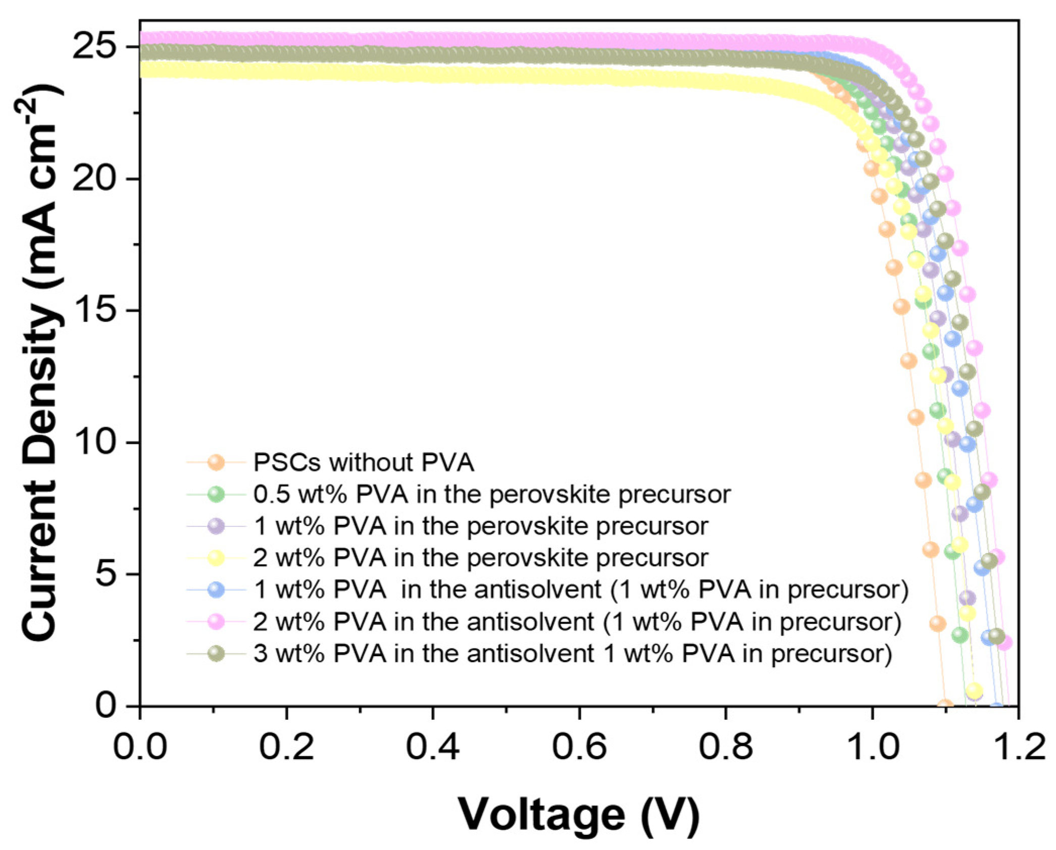
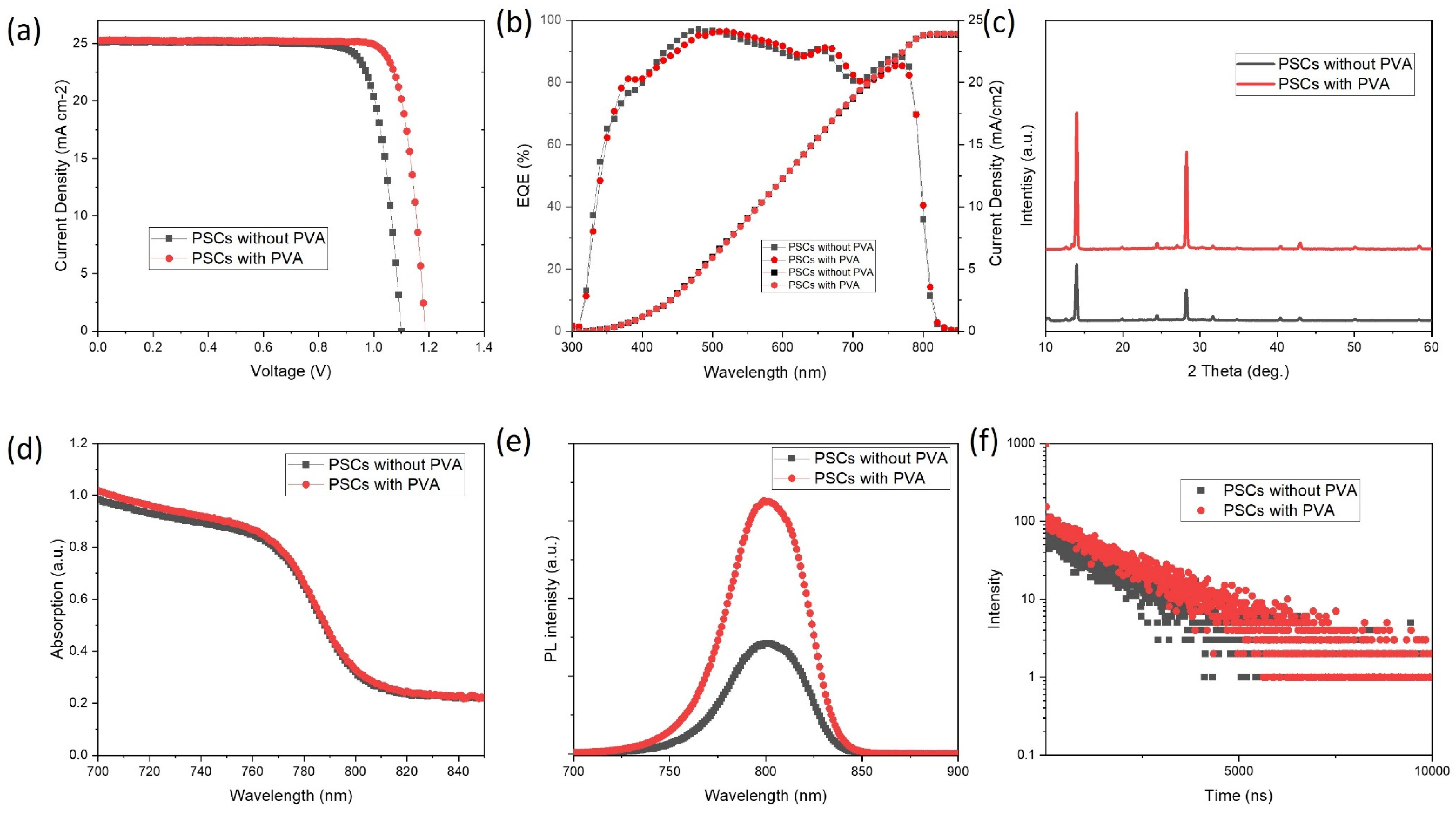
Figure 1. (a) Illustrative representation of the device configuration, (b) molecular structure of Polyvinyl alcohol (PVA), and (c) illustrative depiction of perovskite integrated within the PVA framework.
Energies 17 01629 g001
Figure 2. Scanning Electron Microscopy (SEM) depiction showcasing the comparison between (a) perovskite film without PVA and (b) film with PVA.
Energies 17 01629 g002
Figure 3. (a) Cross section view SEM image of PVA-based device (be) Elemental mapping of Sn, O, N, and Au of the PVA-based device.
Energies 17 01629 g003
Figure 4. Current-Voltage (J-V) characteristic comparison for PSCs for different concentrations of PVA in perovskite precursor and PVA in the antisolvent (1 wt% PVA in precursor).
Energies 17 01629 g004
Figure 5. (a) Current-Voltage (J-V) characteristic comparison for PSCs, highlighting differences between samples with PVA and those without. (b) External quantum efficiency representation for both PSCs with and without PVA. (c) X-ray Diffraction (XRD) patterns for PSCs, showcasing differences due to the presence or absence of PVA. (d) Absorption spectra differences between the PSCs with and without PVA. (e) Comparative normalized photoluminescence (PL) spectra. (f) Time-resolved photoluminescence (TRPL) analysis of PSCs, illustrating contrasts when PVA is integrated versus when it is excluded.
Energies 17 01629 g005
Figure 6. (a,b) UPS of the control film and perovskite films with PVA; (c) Tauc plot of PSCs with and without PVA; (d) the energy band diagram calculated from UPS spectra.
Energies 17 01629 g006
Figure 7. Schematical illustration for the Lead leakage test procedure.
Energies 17 01629 g007
Figure 8. Comparative analysis of lead (Pb) containment in damaged PSCs, highlighting differences between devices with PVA integration and those without.
Energies 17 01629 g008
Figure 9. Static contact angle measurement with water on top of the perovskite films: (a) Control perovskite film, (b) Perovskite film with PVA.
Energies 17 01629 g009
Figure 10. The stability measurement of PSCs, contrasting those incorporated with PVA against those without, under 1 Sun illumination and 75 °C.
Energies 17 01629 g010
Table 1. Photovoltaic parameters for the PSCs with PVA (1 wt% PVA in precursor and 2 wt% in antisolvent) and without PVA.
JscVocFFPCE
PSCs without PVA25.01.10.8122.3
PSCs with PVA25.31.190.8224.7
Table 2. Photovoltaic parameters for the PSCs with PVA in the antisolvent (from 1 wt% to 3 wt% PVA in precursor).
1 wt% PVA in the Antisolvent2 wt% PVA in the Antisolvent3 wt% PVA in the Antisolvent
Jsc25.1946225.2925524.78955
Voc1.169531.189821.17976
FF0.802650.823720.79856
Efficiency23.6507824.7886923.35446
Table 3. Summary of the parameters from fitting to the TRPL decay data.
A1τ1A2τ2
PSCs without PVA10413.4601600
PSCs with PVA5064.38981757
Disclaimer/Publisher’s Note: The statements, opinions and data contained in all publications are solely those of the individual author(s) and contributor(s) and not of MDPI and/or the editor(s). MDPI and/or the editor(s) disclaim responsibility for any injury to people or property resulting from any ideas, methods, instructions or products referred to in the content.

