Article

Muti-Filler Composites Reinforced with Multiwalled Carbon Nanotubes and Chopped Carbon Fibers for the Bipolar Plate of Fuel Cells

1
College of Automotive Engineering, Tongji University, Shanghai 201804, China
2
Clean Energy Automotive Engineering Center, Tongji University, Shanghai 201804, China
*
Author to whom correspondence should be addressed.
Energies 2024, 17(7), 1603; https://doi.org/10.3390/en17071603
Submission received: 1 February 2024 / Revised: 15 March 2024 / Accepted: 23 March 2024 / Published: 27 March 2024
(This article belongs to the Collection Batteries, Fuel Cells and Supercapacitors Technologies)

Abstract

:
To improve the conductivity and flexural strength of bipolar plates for proton-exchange membrane fuel cells, multi-filler-reinforced composites were prepared using graphite, multiwalled carbon nanotubes (MWCNTs), chopped carbon fibers (CCFs), and phenolic resin (PF). The effects of CCF content (0–6 wt.%) and MWCNT content (0–8 wt.%) on the flexural strength, electrical conductivity, interfacial contact resistance (ICR), density, hydrophobicity, and corrosion behavior of the composites were investigated. Results showed that the addition of a small number of CCFs (≤4 wt.%) effectively improved the flexural strength but slightly reduced the electrical conductivity and increased the ICR of the graphite/PF/CCF composites. Further addition of MWCNTs (≤6 wt.%) significantly improved the electrical conductivity and ICR of the graphite/PF/CCF/MWCNT composites, while maintaining high flexural strength. When the composites were filled with 4 wt.% CCFs and 2 wt.% MWCNTs, their electrical conductivity, flexural strength, ICR under 1.38 MPa, and contact angle were 272.8 S/cm, 43.1 MPa, 1.19 mΩ·cm2, and 101.5°, respectively. Compared to unreinforced composites, the electrical conductivity was reduced by 27.2%, the flexural strength was increased by 65.1%, and the composite possessed favorable hydrophobicity as well as corrosion behavior. This work reveals that CCFs and MWCNTs can effectively cooperate to improve composites’ electrical and flexural strength properties.

1. Introduction

Proton-exchange membrane fuel cells (PEMFCs) have been increasingly employed as energy source equipment in transportation and household applications due to their high power density, low environmental pollution, quiet operation, and low operating temperature [1]. The bipolar plates (BPs), an essential part of PEMFCs, are typically divided into graphite, metal, or graphite/polymer composite BPs, according to the different material schemes adopted [2]. Pure graphite bipolar plates, typically fabricated with carbon, graphite powder, or graphitized resin, have gained more attention because of their excellent electrical conductivity and corrosion resistance. Nevertheless, graphite bipolar plates require high-temperature processing above 2500 °C for graphitization, dramatically increasing both the time and economic cost of the process [3]. Metal bipolar plates exhibit outstanding electrical conductivity and excellent gas permeability performance. Unfortunately, metal corrodes quickly in the acidic environment of PEMFCs, which can lead to the poisoning of catalyst particles when dissolved metal ions enter the membrane. Moreover, a passivation film easily forms on a metal surface. This film increases the contact resistance, resulting in a decrease in the performance of the fuel cell [4]. Graphite/polymer composite bipolar plates are mainly made of resin and graphite, offering good corrosion resistance, excellent processing performance, low cost, and good gas permeability of lower than 1 × 10 5   cm 3 · ( s 1 · cm 2 ) 1 under a hydrogen or argon atmosphere [5]; however, as the conductive filler for graphite composite plates, though graphite has high conductivity, its brittle nature leads to the unsatisfactory mechanical performance of the composite. Therefore, many researchers focused on solving the contradiction between electrical conductivity and mechanical properties to simultaneously obtain high electrical and mechanical strength properties [6].
To achieve the mentioned goals, the current research focuses on the addition of different conductive fillers into the graphite/resin system, the reinforcement material including carbon nanotubes (CNTs) [7,8,9,10,11,12,13,14,15], carbon fibers [2,16,17,18,19,20], graphene [18,21,22], and carbon black [17,18]. Among them, multiwalled carbon nanotubes (MWCNTs), which are tube-shaped carbon with a diameter measuring on the nanometer scale, have been considered one of the best reinforcement candidates due to their high aspect ratio, excellent mechanical and electrical conductivity, and thermal conductivity properties [23]. Several pieces of research have studied the effect of MWCNTs on graphite/resin composites [7,8,9,10,11,12,13,14,15]. Shu et al. added MWCNTs into their composites and studied their effect in high-, medium-, and low-crystallinity polypropylene (PP) [7]. The bulk electrical conductivities of composites with various MWCNT contents all exceed 100 S · cm−1, and the flexural strength of the MWCNTs/low-crystallinity PP nanocomposite bipolar plate with 8 phr of MWCNTs was approximately 37% higher than that of the original nanocomposite bipolar plate. Furthermore, they modified MWCNTs [8,9], studying the influence of modified MWCNTs on the performance of the composites. The flexural strength and the bulk electrical conductivity of the MWCNTs/polypropylene nanocomposites were improved by 59% and 505%, respectively, with modified MWCNTs at a content of 8 phr. Ha et al. added MWCNTs into a polypropylene/polyethylene polymer blend sol and used the prepared sol to infiltrate woven carbon fiber [10] and non-woven carbon felt [11] substrates. Their results showed that MWCNTs effectively improved the electrical conductivity of carbon fiber composites. Pattarakamon et al. [12] prepared MWCNT-reinforced graphite/phenolic resin composites with wet and dry methods, respectively. Their composite with 1.0 wt.% MWCNTs via the dry method provided the highest electrical conductivity and optimum mechanical properties, meeting the DOE material requirement for bipolar plates in PEMFC. In Hu’s research [13], he developed high-performance polyvinylidene fluoride/graphite/MWCNT composites with segregated conductive networks. Segregated synergistic conductive networks were observed in the composite after adding MWCNTs, and the composite BP with 5 wt.% MWCNTs exhibited an electrical conductivity of 161.57 S/cm and area-specific resistances of 7.5 m Ω · cm 2 . Kang et al. prepared their composite material with different types of graphite (synthetic graphite, natural graphite, or expanded graphite (EG)), and further modified the EG composite with carbon nanotube sheets (buckypapers) or multiwalled carbon nanotubes (MWCNTs) [15]. To sum up, the above work added MWCNTs as reinforcement fillers and investigated the content, modification method, dispersion method, and dispersion situation of MWCNTs in the graphite/polymer composite system. The results show that MWCNTs, as a carbon material with high performance, can effectively improve the electrical conductivity and slightly increase the flexural strength of the composites.
Chopped carbon fibers (CCFs) are another type of carbon material and have gained much attention due to their good electrical and thermal conductivity, excellent mechanical properties, high strength, and high modulus along the axial direction [16]. Kakati added CCFs to natural graphite/phenolic resin/carbon black [17] and further introduced graphene material into the system [18], finding that the increase in CCF content increased the flexural strength but slightly reduced the electrical conductivity at a CCF content above 5 wt.%. Joong prepared natural graphite/epoxy resin composites reinforced with CCFs and concluded that the composites’ plane conductivity, flexural strength, and modulus increased and then decreased with increasing CCF content [19]. In the study of Bo [20], CCFs treated with three methods were selected as a reinforcement. The composite with CCFs treated with the Fenton reagent for 2 h at a mass content of 4 wt.% exhibited an electrical conductivity, flexural strength, and maximum power density of 240 S/cm, 36 MPa, and 662.75 mW · cm 2 , respectively. Sepehr [2] successfully prepared phenolic resin (PF) composites with graphite, CCFs, and expanded graphite. As presented above, previous research studied the effect of CCFs—the added reinforcement filler—on the performance of composites. Their results show that the addition of CCFs can effectively improve the flexural strength of composites without a significant reduction in electrical conductivity.
To fully use different carbon materials with various sizes, shapes, and performance advantages, achieving ultra-thin bipolar plates with high strength and high conductivity, many recent studies have used multi-conductive fillers to prepare composites for PEMFCs [24,25,26,27]. Radzuan et al. designed a multi-filler composite system by adding MWCNTs [24] to milled carbon fibers (MCFs)/PP/graphene composites. Dongjie added a small number of MWCNTs to CCFs-reinforced PP [25], effectively enhancing the mechanical properties of the composite. Furthermore, microscale CCFs and nanoscale MWCNTs successfully coexisted in the polypropylene matrix, forming multiscale conductive networks, significantly promoting the electrical conductivity of the composite material. Ramírez-Herrera studied the mechanical and corrosion resistance characteristics of their multi-filler system with PP/MWCNTs/carbon nanofibers (CNFs) [26]. In the prepared nanocomposites, combined additions of MWCNTs and CNFs allowed for the production of hybrid nanocomposites with increased strength, preserving their processability even at a total filler content (up to 30 wt.%). In the work of Fatih [27], CFs/epoxy composite laminates were modified with MWCNT superconductor materials to overcome conductivity issues. As described above, compared with that of a single-reinforcement-filler system, the performance of composites can be effectively improved by introducing multi-reinforcement fillers with multiscale and multi-dimension filler construction; however, the multi-reinforcement-filler system mainly adopts MCFs or a high-content resin, and its electrical conductivity is generally not high enough, which makes it challenging to meet the electrical conductivity requirements of bipolar plates. Sirawit [28] fabricated multi-filler composites of graphite, two-dimensional graphene, and MWCNTs, and his results showed that, with the addition of CNTs, the composites’ thermal conductivity and electrical conductivity were improved. Avijit et al. developed multi-conductive-filler composites using carbon black (CB), carbon fiber (CF), and graphene (GP) reinforcement materials with novolac phenol formaldehyde resin (NPFR) [29]. In conclusion, there are few reports on adding MWCNTs and CCFs simultaneously to graphite/resin composites with high-content conductive fillers to preserve their excellent properties. On the other hand, because of the large specific surface area, the high-performance MWCNTs and CCFs are easy to aggregate under the effect of van der Waals forces. Their effective dispersion is the main difficulty in preparing these multi-filler composites.
In this study, with the addition of CCFs and MWCNTs into the graphite/phenolic resin composites, multi-conductive-filler composites containing graphite/CCF/MWCNT were prepared. The effects of the content of CCFs and MWCNTs on the composites’ flexural strength, electrical conductivity, ICR, density, contact angle, and corrosion current density were investigated. In this composite system, graphite, MWCNTs, and CCFs were used simultaneously as conductive fillers to fully utilize the performance advantages of different carbon materials. By optimizing the compositions of composites, a bipolar plate composite with improved electrical conductivity and mechanical properties was obtained.

2. Materials and Methods

2.1. Materials

Graphite was used as the main conductive filler (Qingdao Dongkai Co., Ltd., Qingdao, China, type: natural flake graphite, particle diameter: 25 μm, carbon content: 99.9 wt.%). The thermosetting PF was used as the binder (Jinan Dahui Chemical Technology Co., Ltd., Jinan, China, Model 2123A, particle size: 75 μm, free phenol content: 1.86%). CCFs and MWCNTs were used as reinforcement materials. The CCFs with a diameter of 6 μm, tensile strength of 4900 MPa, and length of 0.5 mm were purchased from Toray Industries. MWCNTs with a length of 10–30 μm, a diameter of 10–20 nm, and a purity over 95% were purchased from Nanjing Xianfeng Nanomaterial Technology, Nanjing, China.

2.2. Sample Preparation

Raw materials, PF, CCFs, and MWCNTs were weighed according to the compositions in Table 1. The MWCNTs were dispersed in an ethanol solution (400 mL, concentration   99.7 % ) with an ultrasonic crusher for 0.5 h, and then, 1/4 graphite powder was added. After that, the slurry was mixed using an electromagnetic stirrer for another 0.5 h and dried at 80 °C in a vacuum oven for 12 h to obtain the homogeneous graphite/MWCNT mixture. The PF and CCFs were added into an ethanol solution (200 mL, concentration   99.7 % ) and then dispersed with an ultrasonic cleaner for 5 min. Then, 3/4 graphite powder was added, and the slurry was mixed with an electromagnetic stirrer for 0.5 h and dried at 80 °C for 12 h to obtain the homogeneous graphite/PF/CCF mixture. The graphite/MWCNT mixture and graphite/PF/CCF mixture were fully crushed and carefully screened through 125 μm screens until no visible mixture was left on the mesh to produce the final composite powder. The test sample was made using compression molding. The 10 g and 5 g mixed powders were weighed to prepare circular and rectangular samples, respectively. The powder was poured into the mold and pressed by a hot press machine (Wuhan Qien, Wuhan, China, Qixing, R-3202) for 50 min at 200 °C under 30 MPa, and the sample was obtained after cooling. Samples for electrical conductivity are fabricated into a cylinder with a 50 mm diameter and 2 mm thickness, and, for flexural strength, a rectangle with 50 mm × 12.6 mm × 1.2 mm.

2.3. Characterizations

The conductivity test of the composites was performed using a four-probe apparatus (Suzhou Jingge, Suzhou, China, Model ST 2258C) according to GB-T 20042.6-2011 [30]. The flexural strength test of the composites was conducted with a three-point bending method according to GB-T13465.1-2014 [31]. The test was performed using a universal testing machine (Instron, Norwood, MA, USA, Model 3365) with a support span of 30 mm and loading speed of 5 mm · m i n 1 . The morphologies of the composite samples were characterized using scanning electron microscopy (SEM, HITACHI, Tokyo, Japan, Model S4800) with magnifications of 1000 and 500. The crystal structures of the raw material and prepared composites were analyzed using X-ray diffraction (XRD, Bruker AXS Germany, Karlsruhe, Germany, Model D8 Advance) with Cu-kα radiation (λ = 0.15418 nm), with an acceleration voltage of 40 kV, acceleration current of 30 mA, scanning angle of 2 θ from 5° to 80° in steps of 0.02 ° , and a scan rate of 6 ° min 1 . The sample density was tested using the Archimedes method according to GB-T 20042.6-2011 [30]. The interfacial contact resistance (ICR) was tested using experimental equipment and schemes based on Ha’s work [32]. A low-resistance measuring instrument was connected to the two gold-plated copper electrodes through wire clamps, and a constant current of 1 A was applied to the driving terminal of the wire clamps. During the test, the test sample was first placed between two gas diffusion layers (SGL, 28BC), and these three components were then placed together between two copper electrodes to obtain the electrical resistance value, R 1 . Then, a single GDL was placed between the two copper electrodes, and the electrical resistance value, R 2 , was measured. The compression pressure (0.2–1.8 MPa) was applied to the copper electrodes through a universal tester (Instron, Norwood, MA, USA, Model 3365). The ICR of composites can be calculated using the tested values, R 1 and R 2 , via Equations (1)–(4):
R 1 = 2 R e l e + 2 R e l e c p + 2 R c p + 2 R b p c p + R b p ,
R 2 = 2 R e l e + 2 ρ e l e c p + R c p ,
A S R = R b p + 2 · I C R = R 1 R 2 R c p ,
I C R =   R b p c p = A S R R b p 2 ,
where R e l e was the bulk resistance of the copper electrode, R e l e c p was the interfacial contact resistance between the copper electrode and the carbon paper, R c p was the bulk resistance of the GDL carbon paper, R b p c p was the interfacial contact resistance between the composite and the carbon paper, and A S R was the area-specific resistance of the composite material for the bipolar plate, which consisted of the area-specific bulk resistance of the composite, R b p , and the interfacial contact resistance between the composite and the carbon paper, I C R .
The bulk density of the sample was tested using the Archimedes method. The hydrophobicity of the prepared composites was estimated with the surface contact angle. The surface contact angle was measured using a contact angle measuring instrument (Shimadzu, Kyoto, Japan, JY-82B Kruss DSA). An electrochemical test of a typical three-electrode system built in a glass cell was employed to evaluate the corrosion performance of the prepared composites. The sample was used as a working electrode, Pt mesh as a counter electrode, and Ag/Agcl electrode as a reference electrode. The test sample was immersed in 0.5 M H 2 SO 4 at 70 °C. Air and hydrogen were purged to simulate anode and cathode conditions, respectively. Potentiodynamic tests were performed with an electrochemical workstation (Shanghai Chenhua Instruments, Shanghai, China, CHI 660E) from −1 V to 1 V with a scanning rate of 2 mV/s.

3. Results and Discussion
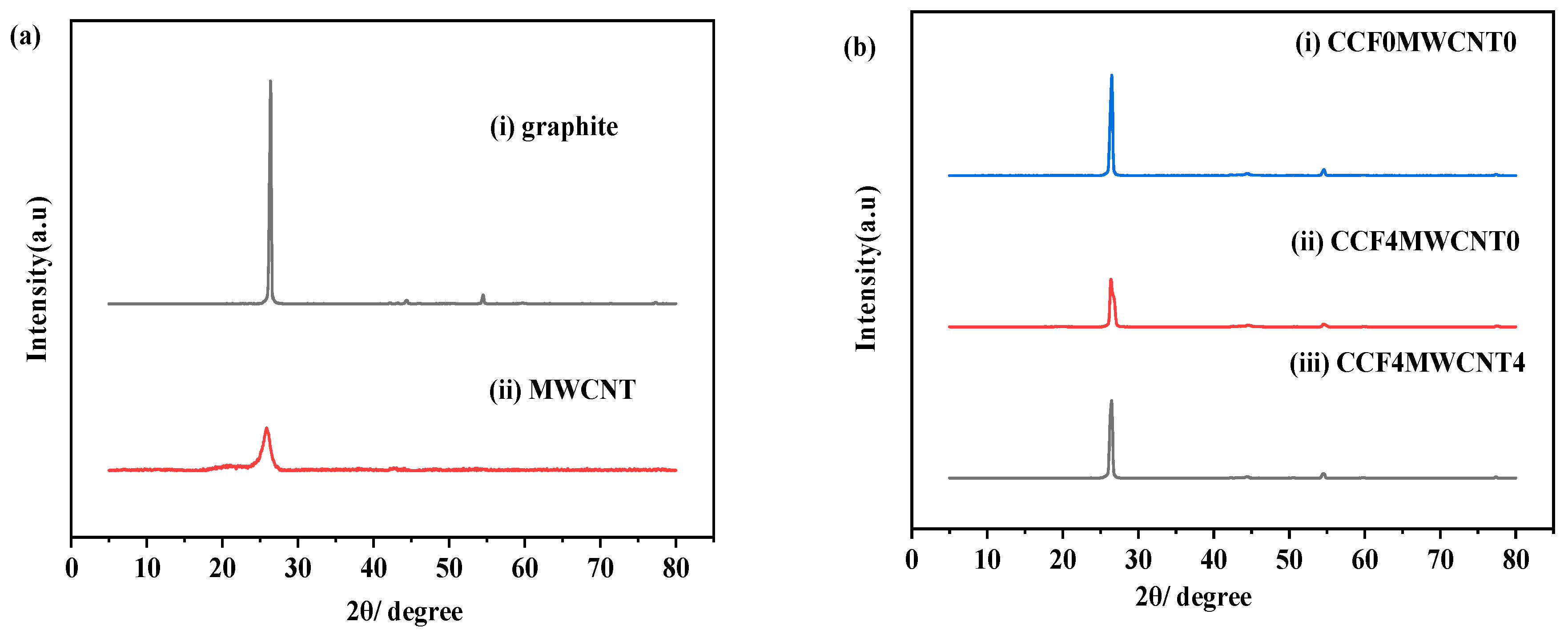
3.1. XRD Analysis

As shown in Figure 1, an XRD analysis examined the micro-structures of the graphite and MWCNT raw materials in addition to the prepared CCF- and MWCNT-reinforced PF composites. The crystal structures of graphite and MWCNTs are confirmed in Figure 1a. As phenolic resin and CCFs lack a crystalline structure, their properties could not be determined through the XRD analysis. MWCNTs reflected carbon (C) contents at the 2θ of 25.94°. Graphite showed the strongest peak corresponding to the (002) plane, and there were also peaks matching (110) and (004) diffraction planes. As for the graphite/PF, graphite/PF/CCF, and graphite/PF/CCF/MWCNT composites, they all exhibited the strongest peaks corresponding to the (002) plane and also matched graphite at the (101) and (004) planes in Figure 1b. It can be concluded that hot-pressing treatment and the addition of CCFs as well as MWCNTs have little effect on the crystal structure type of the composites; however, the intensity of the strongest peak of the composite corresponding to the (002) plane decreased obviously when the CCFs of the non-crystal structure were added instead of the same amount of graphite (Figure 1b), indicating that the crystallinity of the composite decreased. After introducing MWCNTs with a crystal structure to the system, the intensity of the strongest peak of the composite increased (Figure 1b), indicating that the crystallinity increased. This phenomenon demonstrates that adding different carbon materials affects the crystallinity of the composites. It can be inferred that the crystal properties of the materials used for preparing composite plates will affect the properties of the final composite.

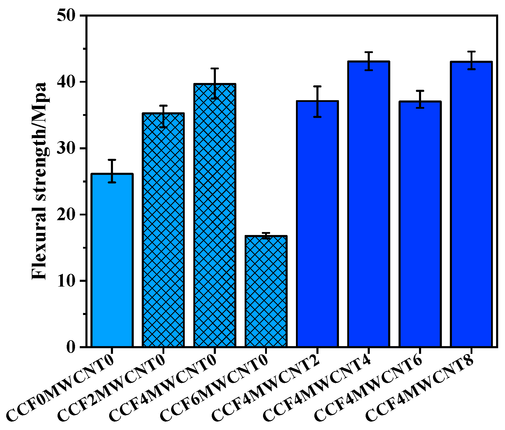
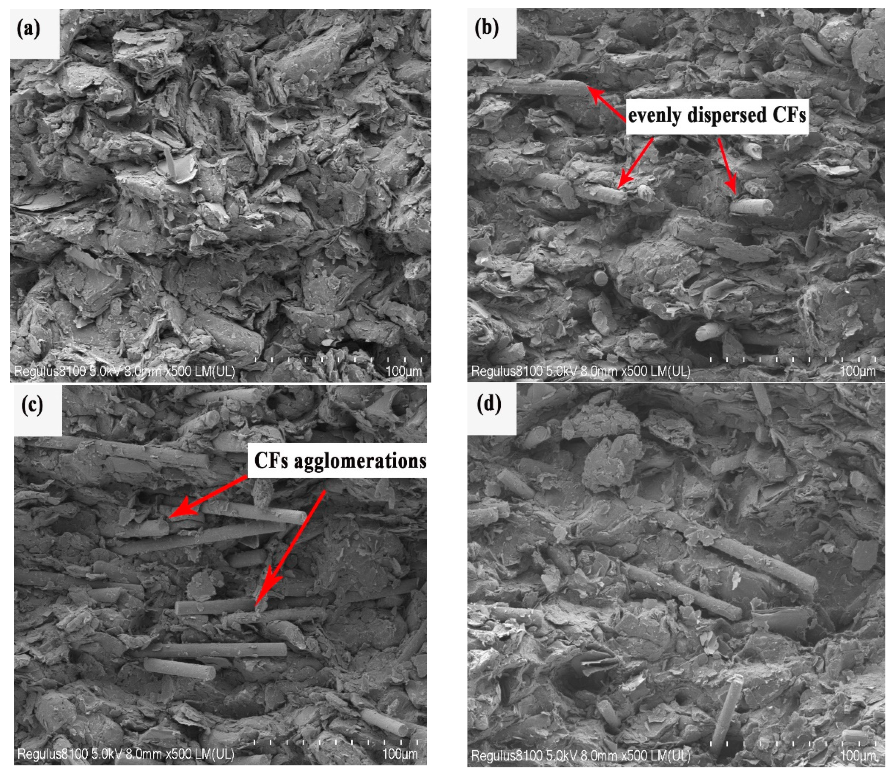
3.2. Flexural Strength of Composites

As shown in Figure 2, the flexural strength of graphite/PF composites reinforced with different contents of CCFs and MWCNTs according to the compositions shown in Table 1 was tested.
As shown in Figure 2, when the added CCF content increased, the composite’s flexural strength first increased significantly and then decreased. When the content of CCFs was 4 wt.%, the maximum flexural strength of the composite was 39.7 MPa, which was 52.1% higher than for the one without CCFs (26.1 MPa). It can be concluded that CCFs successfully join the composite system, and a slight amount of CCFs (2–4 wt.%) can effectively enhance the flexural strength of the composites. The result can be seen in Figure 3, which shows SEM images of the fractured cross-section morphology of CCF- and MWCNT-reinforced PF composites. Figure 3b shows that a small number of CCFs were evenly dispersed among graphite particles. These CCFs, which possessed high strength and modulus along the axial direction, were bonded to graphite particles through PF resin, which could withstand greater external forces and prevent the fracturing as well as deformation of composites, thus improving flexural strength. In addition, using CCFs of a large specific surface area instead of graphite particles of a small specific surface area increased the interface contact area between carbon material and resin as well as the load required for fracture failure, also favoring flexural strength; however, when the CCF content was further increased to 6 wt.%, the flexural strength was significantly reduced, even lower than that of the composites without CCFs. This was because CCF agglomerations appear (Figure 3c) due to the large specific area of CCFs. These CCFs became close to each other and could not be in close contact with graphite particles or resins, resulting in voids (Figure 4c) and a reduction in density. On the other hand, compared with the short CCFs at the fracture surface with 4 wt.% CCFs (Figure 3b), the length of exposed CCFs at the fracture surface with 6 wt.% CCFs were significantly increased (Figure 3c). At this time, CCFs, with a large specific surface area, reduced the thickness of the resin wrapped on the surface of the carbon material, reducing the bond strength between the carbon material and resin interface and harming the flexural strength. Therefore, MWCNTs were further added to the composite with CCFs 4 wt.%, which showed the highest flexural strength, to optimize its performance.
As shown in Figure 2, the flexural strength of graphite/PF/CCF/MWCNT composites increased slightly in the fluctuation and remained at a high level with increasing MWCNT content (0–8 wt.%). When the MWCNT content was 4 wt.%, the flexural strength of the composite was the highest at 43.1 MPa, 65.1% higher than that without CCFs and MWCNTs, and 8.6% higher than that with 4 wt.% CCFs but no MWCNTs. The enhancement resulting from added MWCNTs was lower than that of CCFs. Due to the good dispersion condition, these high-strength MWCNTs successfully coexisted and collaborated with CCFs (Figure 3e), which connected ingredients in the composites and favored flexural strength. Moreover, nanoscale MWCNTs could be inserted into spaces between other carbon materials, even MWCNTs aggregated at 8 w.% (Figure 3f), to reduce voids and increase material compactness (as shown in the SEM images of the horizontal surface morphology of composites in Figure 4d,f), finally improving flexural properties. Nevertheless, adding MWCNTs might also have disadvantages in terms of flexural strength. The specific surface area of MWCNTs was much larger than that of graphite particles. With the addition of MWCNTs, the contact area between the conductive fillers and PF resin increased, and the thickness of the resin was reduced. Thus, the insufficient resin could not fully wrap the carbon material, reducing the interfacial bonding strength. When these weak bonding interfaces were subjected to bearing a load, compared to the shorter CCFs at the fracture surface of a composite with 4 wt.% CCFs (Figure 3b), more and longer CCFs were pulled out (Figure 3d), reducing the flexural strength of a composite when 2 wt.% MWCNTs were further added.

3.3. Electrical Conductivity of Composites

Figure 5 illustrates the electrical conductivity of the prepared CCF- and MWCNT-reinforced PF composites. As Figure 5 shows, compared with composites without CCFs, the electrical conductivity of the composite decreased slightly from 214.4 S/cm to 188.4 S/cm after 2 wt.% CCFs were added, reducing it by 12.1%. This was because CCFs’ amorphous structures produced lower electrical conductivity than graphite particles with highly crystalline structures did [33]. When the amount of CCFs increased, the composites’ electrical conductivity slightly changed. This phenomenon could be attributed to the fibrous structure of CCFs and the reduced thickness of resin due to the large specific surface area of CCFs (Section 3.2). The fibrous structure of CCFs can effectively connect graphite particles and the thicker resin to form conductive networks, reducing the low-conductivity CCFs’ hindrance effect on the system’s current flow even when CCF aggregation appears at 6 wt.%.
When MWCNTs were added, the electrical conductivity of the composite was greatly improved (Figure 5). The composites’ electrical conductivity with 2 wt.% MWCNTs and 4 wt.% CCFs was 272.8 S/cm, which was 41.3% higher than that of the composites with 4 wt.% CCFs but no MWCNTs, and 27.2% higher than that of the composites without any CCFs and MWCNTs. MWCNTs were a typical conductive material with nanoscale and one-dimensional structures [18]. As shown in Figure 3e, the body of filamentous MWCNTs was stretched and was well dispersed, adhering to the rod-like structure surface of CCFs. These well-dispersed numerous linear MWCNTs could effectively connect both graphite particles and CCFs, increasing the effective conductive networks in the composites. The new MWCNTs’ conductive channels, which work together with the conductive CCFs and graphite, reduce the resistance to electron transport in the composite, improving its electrical conductivity. On the other hand, MWCNTs, with large specific surface areas, reduced the thickness of the PF resin layer wrapped on the fillers, as mentioned in Section 3.2, favoring the electron tunneling effect between conductive particles, which also improved the electrical conductivity. The electrical conductivity was almost unchanged when the MWCNT content increased from 2 wt.% to 6 wt.%; however, the electrical conductivity was significantly reduced when the MWCNT amount was further increased to 8 wt.%. As seen from Figure 3f, MWCNTs in the composite were evidently intertwined and agglomerated in this situation. These MWCNT agglomerations hindered the conductive networks’ wide divergence, reducing the composites’ electrical conductivity regardless of the improvement in their compactness (Figure 4f).

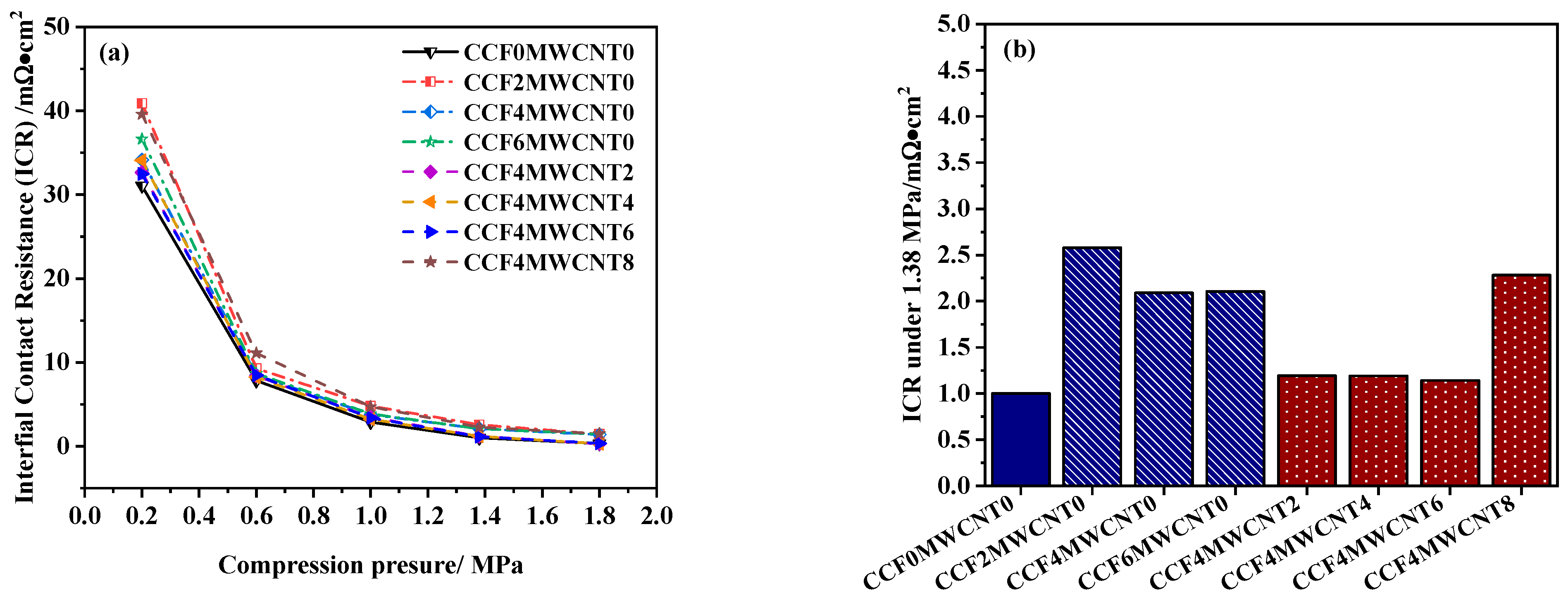
3.4. ICR of Composites

The ICR between the bipolar plate and gas diffusion layer (GDL) adds an ohmic drop, almost equivalent to the membrane’s. It can cause severe losses during cell performance if not paid enough attention [34]. The ICR of the prepared graphite/PF/MWCNT/CCF composites was evaluated under compression pressure from 0.2 to 1.8 Mpa in Figure 6. As can be seen from Figure 6, the ICR of the composite increased after the addition of CCFs. This result occurred because the added CCFs decreased the electrical conductivity of the composites, as shown in Figure 5, resulting in lower electrical conductivity on the composite surface. When the CCF content increased, the ICR of the composites decreased gradually. The maximum ICR of composites occurred when the CCF content was 2 wt.%, reaching 2.58 m Ω · cm 2 at 1.38 MPa. The ICR was mainly determined by the electrical conductivity and morphology of the composite surface. Though the electrical conductivity of the composites changed little when the CCF content increased from 2 wt.% to 6 wt.%, as shown in Figure 5, the number of exposed CCFs on the surface of the composites increased (as the SEM morphology of composites in Figure 4a–c showed). These exposed CCFs could be sufficiently contacted with the GDL, which would increase the practical contact areas between the composite and GDL and make it easier for electrons to pass through the contact surface between these two parts, thus improving the interface conductivity.
When the MWCNT content increased from 0 to 6 wt.%, the ICR of the composite decreased (Figure 6) due to the improved electrical conductivity of the composites, as shown in Figure 5; however, when the MWCNT content further increased to 8 wt.%, the aggregation of MWCNTs caused a significant decrease in the electrical conductivity (Figure 5) and then decreased the ICR of the composite, resulting in poor interfacial conductivity.
As shown above, the addition of CCFs and MWCNTs had a significant effect on the ICR of composites, but the ICR of the prepared composites under 1.38 MPa was still less than 3 m Ω · cm 2 , and favorable interfacial conductivities were maintained.

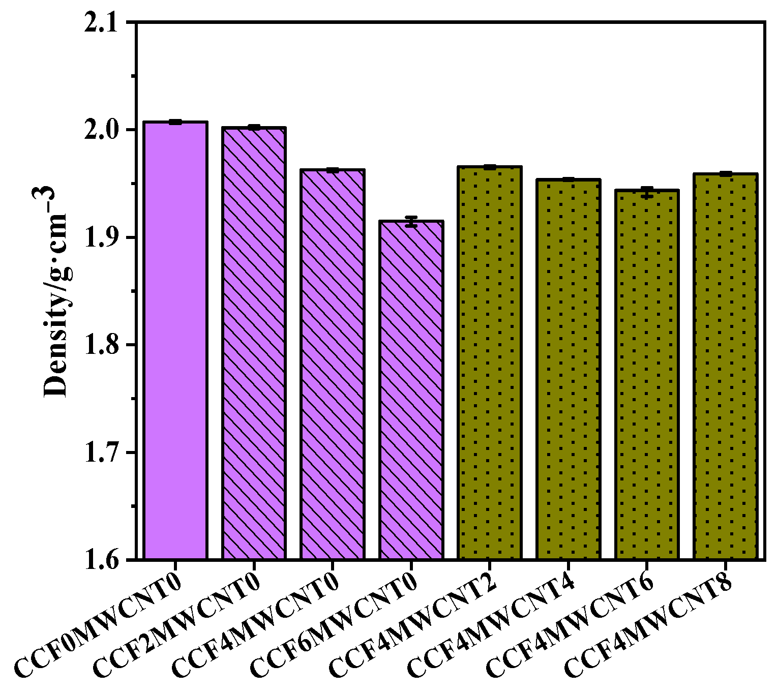
3.5. Density of Composites

The density of bipolar plates is a critical property in reducing the weight and cost of PEMFCs. Figure 7 shows the density of the prepared CCF- and MWCNT-reinforced PF composites. As seen from Figure 7, when the amount of CCFs increased, the density of composites gradually decreased due to the lower density of CCFs than the graphite particles. Furthermore, CCFs tended to agglomerate (Figure 3c) as their content grew greater, resulting in more pores and voids appearing in the composites.
When MWCNTs were added, with the increase in MWCNT content (2–6 wt.%) the density of the composite decreased at first (Figure 7), owing to the lower density. When the content of MWCNTs reached 8 wt.%, the density of the composite recovered slightly. At this time, the surface voids of the composite were reduced compared to the one with 6 wt.% MWCNTs (Figure 4e,f). This phenomenon might be because the high-content, nano-sized MWCNT particles (even after agglomerates) had filled large voids among other carbon materials, which increased the compactness, thus improving the density of the composite.
In addition, although the density of CCFs was similar to that of MWCNTs, the influence of CCFs on the density of a composite was obviously more significant. This result might be attributed to the nanoscale one-dimensional structure of MWCNTs, which made it possible for MWCNTs to fill the gap between large-sized graphite and CCFs. This filling effect improved the porosity, thus increasing the density.

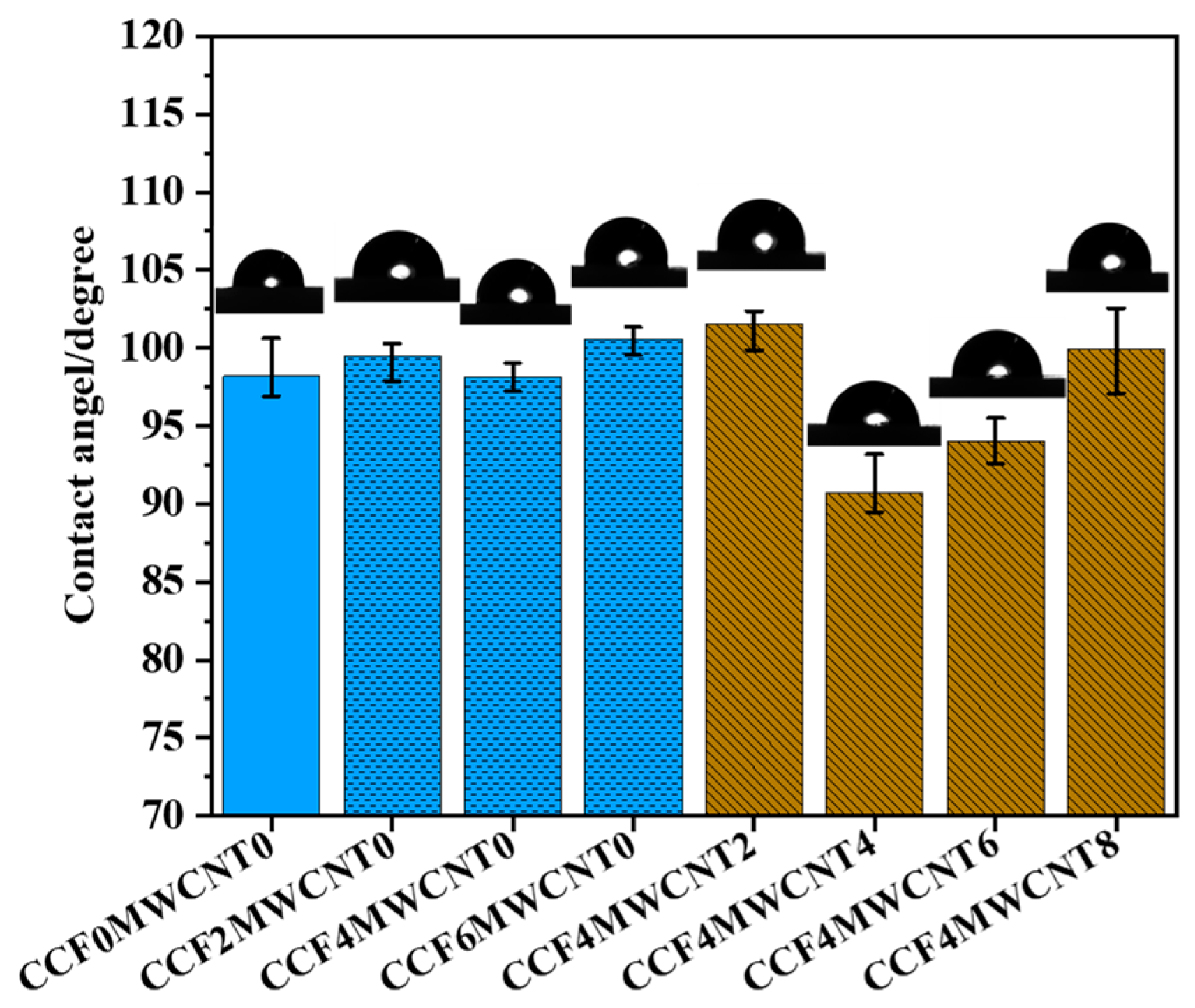
3.6. Hydrophobicity Behavior of Composites

The fuel cells generate water via electrochemical reactions at the cathode. Due to the low temperature of the fuel cell (70–80 °C), the produced water exists mainly in the form of liquid water. Once the liquid water adheres to the bipolar plate and cannot be removed in time, it will block the flow channel and cause the uneven distribution of reaction gas, which will increase the concentration loss, thus reducing the output performance. Therefore, hydrophobic behavior is an essential property of the bipolar plate. Hence, the contact angle of graphite/PF/MWCNT/CCF composites was tested as shown in Figure 8.
Figure 8 indicates the contact angle of graphite/PF/MWCNT/CCF composites with different CCF contents and MWCNT contents. As shown in Figure 8, when the content of CCFs increased, the contact angle of the composite did not change significantly and stayed around 99°, showing rather good hydrophobicity. A good-hydrophobicity composite could expel the liquid water in the GDL and flow channel, favoring the transmission of the reactant gas into the catalyst layer and participating in the electrochemical reaction there, which will benefit the performance of the fuel cell. When 2 wt.% MWCNTs were added, the composites’ contact angle scarcely changed; however, when the MWCNT content increased to 4 wt.%, the contact angle decreased clearly, and the lowest value was 90.7°. This was because, compared with non-polar graphite particles, MWCNTs contained a large number of hydrophilic groups (such as carboxyl groups) on the surfaces, which showed stronger hydrophilicity. For composites with lower contact angles, the ability of bipolar plates to absorb water from the GDL decreased, which might lead to difficulty in water transfer [4], insufficient reactant gas transfer, and degradation in output voltage performance. When the MWCNT content increased from 4 wt.% to 8 wt.%, the contact angle of the composite increased gradually, indicating better hydrophobicity. This improvement in hydrophobicity might be caused by the increased number of conductive fillers exposed to the composite surfaces [13].

3.7. Corrosion Behavior

Corrosion behavior under fuel cell working conditions is an essential criterion of bipolar plate materials, which is usually tested with electrochemical experiments. As the results of the potentiodynamic test purged with air and hydrogen in Figure 9 show, when the CCF content increased from 0 to 6 wt.%, when purged with air, the corrosion current density of the composite increased from 0.813 μ A·cm−2 to 2.122 μ A·cm−2; when purged with hydrogen, the corrosion current density of the composite increased from 0.342 μ A·cm−2 to 1.843   μ A·cm−2. The addition of CCFs reduced the corrosion performance of the composites. This might be due to the better corrosion behavior of graphite than CCFs. Additionally, the added CCFs reduced the density of composites (Figure 7) and increased their porosity, resulting in more active sites on the composites’ surfaces; however, the increase in corrosion current density was slight because of the small number of added CCFs.
As the results of the potentiodynamic test in Figure 10 show, when the MWCNT content increased from 0 wt.% to 6 wt.%, the corrosion current density of the graphite/PF/CCF/MWCNT composites increased; when purged with air, the corrosion current density increased from 1.672   μ A·cm−2 to 6.124   μ A·cm−2; and when purged with hydrogen, the corrosion current density increased from 0.728 μ A·cm−2 to 3.817 μ A·cm−2. When the content of MWCNTs was less than 4 wt.%, the increase in the corrosion current density of the composite was minimal; when the content of MWCNTs increased from 4 wt.% to 6 wt.%, the corrosion current density of the composite sharply increased. It could be concluded that the added MWCNTs were harmful to the corrosion performance, which might also be due to the better corrosion behavior of graphite and the increase in density (Figure 7) and active sites of the composite; however, when the content of MWCNTs increased from 6 wt.% to 8 wt.%, the corrosion current density of the composite decreased. As shown in Figure 7, in this situation, the density of composites increased (Figure 7) because of the supplementary role of MWCNTs, thus reducing the active sites for corrosion reactions.

4. Conclusions

In this study, multi-conductive-filler composites with graphite, CCFs, and MWCNTs were successfully prepared. The effects of CCF content and MWCNT content on the flexural strength, electrical conductivity, ICR, density, hydrophobicity, and corrosion behavior of the composites were investigated. The results showed that the addition of a small number of CCFs (≤4 w.%) could effectively improve the flexural strength owing to the well-dispersed CCFs, which had a high strength and modulus, being firmly bonded to graphite particles through PF resin, and due to their large specific surface area increasing the interface contact area between the carbon material and resin. Additionally, a small number of CCFs (≤4 wt.%) reduces the density of a composite and maintains its good hydrophobicity as well as corrosion behavior; however, it was not beneficial for the electrical conductivity and the ICR. The reduction in electrical conductivity is mainly caused by the lower electrical conductivity of CCFs; however, when the content of CCFs exceeds 6 wt.%, the flexural strength of the composite decreased significantly because of the appearance of CCF aggregations and reduced thickness of the resin wrapped on the surface of the carbon material. At the optimum CCF content of 4 wt.%, the flexural strength of the composite increased by 52.1%, the electrical conductivity decreased by 10.0%, the ICR increased by 100.0%, and the density reduced by 2.0%. MWCNTs were further added based on the optimum content of CCFs. When the content of MWCNTs was less than 6 wt.%, the electrical conductivity and ICR properties of the composite were obviously improved, and the flexural strength was slightly increased. This may be because the body of filamentous MWCNTs was stretched and was well dispersed, adhering to the rod-like structure surface of CCFs. In terms of the electrical properties, the added well-dispersed numerous linear MWCNTs increased the effective conductive networks in the composites, which worked together with the conductive CCFs and graphite, reducing the resistance to electron transport in the composite. Furthermore, MWCNTs, with large specific surface areas, reduced the thickness of the PF resin layer wrapped on the fillers, favoring the electron tunneling effect between conductive particles, thus improving its electrical conductivity and ICR. Regarding the flexural strength, the high-strength and high-module MWCNTs and CCFs would bear the load together. Additionally, nanoscale MWCNTs could be inserted into spaces between CCFs and other carbon materials to reduce voids and increase material compactness, ultimately improving the flexural properties; however, the hydrophobicity of the composites obviously decreased when the MWCNT content was 4–6 wt.%. With 2 wt.% MWCNTs and 4 wt.% CCFs, the electrical conductivity of the composite was 272.8 S/cm, the flexural strength was 43.1 MPa, the ICR was 1.19 m Ω · cm 2 under 1.38 MPa, the contact angle was 101.5°, and the corrosion current density was 2.545 μ A·cm−2 and 0.828 μ A·cm−2 when the test was purged under air and hydrogen, respectively. It can be seen that the cooperation of CCFs and MWCNTs can effectively improve the performance of a composite, and bipolar plate composites with improved electrical conductivity as well as mechanical strength are obtained.
In our future work, the gas permeability will be further tested to obtain a more comprehensive and accurate understanding of the prepared composites.

Author Contributions

Conceptualization, J.L., S.X. and H.W.; methodology, H.W.; formal analysis, H.W., G.C., S.X. and J.L.; investigation, H.W.; resources, J.L.; data curation, H.W.; writing—original draft preparation, H.W.; writing—review and editing, S.X., J.L. and H.W.; supervision, G.C.; project administration, J.L.; funding acquisition, J.L. All authors have read and agreed to the published version of the manuscript.

Funding

This work was supported by a National Natural Science Foundation of China Grant, grant number 21776221, which is gratefully acknowledged.

Data Availability Statement

The original contributions presented in the study are included in the article, further inquiries can be directed to the corresponding author.

Conflicts of Interest

The authors declare no conflicts of interest.

References

  1. Lee, D.; Choe, J.; Nam, S.; Lim, J.W.; Choi, I.; Lee, D.G. Development of non-woven carbon felt composite bipolar plates using the soft layer method. Compos. Struct. 2017, 160, 976–982. [Google Scholar] [CrossRef]
  2. Sepehr, S.; Majid, K.; Mohammad, M. Fabrication of multi-filler thermoset-based composite bipolar plates for PEMFCs applications: Molding defects and properties characterizations. Int. J. Hydrogen Energy 2020, 45, 14119–14132. [Google Scholar]
  3. Roßberg, K.; Trapp, V. Graphite-Based Bipolar Plates; SGL Technologies GmbH: Meitingen, Germany, 2010; p. 2. [Google Scholar]
  4. Li, Y.; Jia, X.; Zhang, W.; Fang, C.; Wang, X.; Qin, F.; Yamaura, S.; Yokoyama, Y. Effects of Alloying Elements on the Thermal Stability and Corrosion Resistance of an Fe-based Metallic Glass with Low Glass Transition Temperature. Metall. Mater. Trans. A 2013, 45, 2393. [Google Scholar] [CrossRef]
  5. Jeong, K.I.; Oh, J.; Song, S.A.; Lee, D.; Kim, S.S. A review of composite bipolar plates in proton exchange membrane fuel cells: Electrical properties and gas permeability. Compos. Struct. 2021, 262, 113617. [Google Scholar] [CrossRef]
  6. Planes, E.; Flandin, L.; Alberola, N. Polymer composites bipolar plates for PEMFCs. Energy Procedia 2012, 20, 311–323. [Google Scholar] [CrossRef]
  7. Shu, H.L.; Chuan, Y.Y.; Cheng, C.W.; Yu, F.L.; Chen, C.M.M.; Ching, H.Y.; Ming, C.T.; Ming, Y.Y.; Min, C.H.; Shuo, J.L.; et al. Preparation and properties of carbon nanotube/polypropylene nanocomposite bipolar plates for polymer electrolyte membrane fuel cells. J. Power Sources 2008, 185, 1225–1232. [Google Scholar]
  8. Shu, H.L.; Cheng, C.W.; Chuan, Y.Y.; Min, C.H.; Chen, C.M.M.; Ming, C.T.; Ay, S.; Ming, Y.Y.; Yu, F.L.; Po, L.L. Preparation and properties of functionalized multiwalled carbon nanotubes/polypropylene nanocomposite bipolar plates for polymer electrolyte membrane fuel cells. J. Power Sources 2010, 195, 263–270. [Google Scholar]
  9. Min, C.H.; Shu, H.L.; Yu, F.L.; Cheng, C.W.; Han, M.T.; Chen, C.M.M.; Shie, H.L.; Ming, Y.Y.; Po, L.L. Polypropylene-grafted multiwalled carbon nanotube reinforced polypropylene composite bipolar plates in polymer electrolyte membrane fuel cells. Energy Environ. Sci. 2011, 4, 543. [Google Scholar]
  10. Ha, E.L.; Song, H.H.; Seung, A.S.; Seong, S.K. Novel fabrication process for carbon fiber composite bipolar plates using sol gel and the double percolation effect for PEMFC. Compos. Struct. 2015, 134, 44–51. [Google Scholar]
  11. Ha, E.L.; Yong, S.C.; Seong, S.K. Feasibility study on carbon-felt-reinforced thermoplastic composite materials for PEMFC bipolar plates. Compos. Struct. 2017, 180, 378–385. [Google Scholar]
  12. Pattarakamon, C.; Jantrawan, P. Wet vs. dry dispersion methods for multiwall carbon nanotubes in the high graphite content phenolic resin composites for use as bipolar plate application. Electrochim. Acta 2015, 158, 1–6. [Google Scholar]
  13. Hu, B.; Chang, F.L.; Xiang, L.Y.; He, G.J.; Cao, X.W.; Yin, X.C. High performance polyvinylidene fluoride/graphite/multiwalled carbon nanotubes composite bipolar plate for PEMFC with segregated conductive networks. Int. J. Hydrogen Energy 2021, 46, 25666–25676. [Google Scholar] [CrossRef]
  14. Yang, B.L.; Choong, H.L.; Kyung, M.K.; Dae, S.L. Preparation and properties on the graphite/polypropylene composite bipolar plates with a 304 stainless steel by compression molding for PEM fuel cell. Int. J. Hydrogen Energy 2011, 36, 7621–7627. [Google Scholar]
  15. Kang, Y.; Daniel, A.; Ayou, H.; Jim, P.Z.; Zhiyong, L.; Nam, N. Highly Conductive and Strong Graphite-Phenolic Resin Composite for Bipolar Plate Applications. Energy Fuels 2017, 31, 14320–14331. [Google Scholar]
  16. Kyungmun, K.; Sunghyun, P.; Ahrae, J.; Kise, L.; Hyunchul, J. Development of ultralight and thin bipolar plates using epoxy-carbon fiber prepregs and graphite composites. Int. J. Hydrogen Energy 2017, 42, 1691–1697. [Google Scholar]
  17. Kakati, B.K.; Sathiyamoorthy, D.; Verma, A. Electrochemical and mechanical behavior of carbon composite bipolar plate for fuel cell. Int. J. Hydrogen Energy 2010, 35, 4185–4194. [Google Scholar] [CrossRef]
  18. Biraj, K.K.; Avijit, G.; Anil, V. Efficient composite bipolar plate reinforced with carbon fiber and graphene for proton exchange membrane fuel cell. Int. J. Hydrogen Energy 2013, 38, 9362–9369. [Google Scholar]
  19. Joong, H.L.; Yun, K.J.; Chang, E.H.; Nam, H.K.; Peng, L.; Hong, K.L. Effect of carbon fillers on properties of polymer composite bipolar plates of fuel cells. J. Power Sources 2009, 193, 523–529. [Google Scholar]
  20. Bo, L.; Zhigang, S.; Liang, H.; Yong, G.; Shucheng, S. A novel graphite/phenolic resin bipolar plate modified by doping carbon fibers for the application of proton exchange membrane fuel cells. Prog. Nat. Sci. Mater. Int. 2020, 30, 876. [Google Scholar]
  21. Ali, A.; Morteza, S.; Mahmood, M.; Hadi, N.P. High performance polymeric bipolar plate based on polypropylene/graphite/graphene/nano-carbon black composites for PEM fuel cells. Renew. Energy 2016, 99, 867–874. [Google Scholar]
  22. Runlin, F.; Junsheng, Z.; Yuhang, P.; Jing, C.; Zize, Z.; Dongmei, Y.; Cunman, Z.; Pingwen, M. The conductive network optimization of composite graphite plates and its orphological analysis. Chem. Eng. J. 2022, 446, 136652. [Google Scholar]
  23. Shu, H.L.; Chih, H.H.; Chen, C.M.M.; Chuan, Y.Y.; Yu, F.L.; Cheng, C.W. Preparation and properties of carbon nanotube-reinforced vinyl ester/nanocomposite bipolar plates for polymer electrolyte membrane fuel cells. J. Power Sources 2008, 176, 175–182. [Google Scholar]
  24. Radzuan, N.M.; Sulong, A.B.; Somalu, M.R.; Abdullah, A.T.; Husaini, T.; Rosli, R.E.; Majlan, E.H.; Rosli, M.I. Fibre orientation effect on polypropylene/milled carbon fiber composites in the presence of carbon nanotubes or graphene as a secondary filler: Application on PEM fuel cell bipolar plate. Int. J. Hydrogen Energy 2019, 44, 30618–30626. [Google Scholar] [CrossRef]
  25. Dongjie, Z.; Haibin, Z.; Zhiyong, G.; Yu, G.; Qing, L.; Guilong, W.; Guoqun, Z. Surface treatment of multiwalled carbon nanotubes and the formation of the multiscale conductivity network in long carbon fiber reinforced polypropylene. Polym. Compos. 2022, 43, 4645–4659. [Google Scholar]
  26. Ramírez-Herrera, C.A.; Tellez-Cruz, M.M.; Pérez-González, J.; Solorza-Feria, O.; Flores-Vela, A.; Cabañas-Moreno, J.G. Enhanced mechanical properties and corrosion behavior of polypropylene/multiwalled carbon nanotubes/carbon nanofibers nanocomposites for application in bipolar plates of proton exchange membrane fuel cells. Int. J. Hydrogen Energy 2021, 46, 26110–26125. [Google Scholar] [CrossRef]
  27. Fatih, D.; Alparslan, T.; Kadir, A.; Selahattin, C. Carbon nanotube (CNT) modified carbon fiber/epoxy composite plates for the PEM fuel cell bipolar plate application. Int. J. Hydrogen Energy 2023, 48, 1090–1106. [Google Scholar]
  28. Sirawit, W.; Manunya, O.; Chanchira, J.; Panagiotis, K.; Sarawut, R. Highly filled graphite/graphene/carbon nanotube in polybenzoxazine composites for bipolar plate in PEMFC. Int. J. Hydrogen Energy 2020, 45, 30898–30910. [Google Scholar]
  29. Avijit, G.; Pranab, G.; Pinakeshwar, M.; Anil, V. Effect of carbon fiber length and graphene on carbon-polymer composite bipolar plate for PEMFC. J. Solid State Electrochem. 2014, 18, 3427–3436. [Google Scholar]
  30. GB-T 20042.6-2011; Proton Exchange Membrane Fuel Cell—Part 6: Test Method of Bipolar Plate Properties. Standards Press of China: Beijing, China, 2011.
  31. GB-T13465.1-2014; Test Method of Impermeable Graphite Materials—Part 1: General of Test Method for Mechanical Properties. Standards Press of China: Beijing, China, 2014.
  32. Ha, N.Y.; Jun, W.L.; Jung, D.S.; Dai, G.L. A graphite-coated carbon fiber epoxy composite bipolar plate for polymer electrolyte membrane fuel cell. J. Power Sources 2011, 196, 9868–9875. [Google Scholar]
  33. Mathur, R.B.; Dhakate, S.R.; Gupta, D.K.; Dhami, T.L.; Aggarwal, R.K. Effect of different carbon fillers on the properties of graphite composite bipolar plate. Mater. Process. Technol. 2008, 203, 184–192. [Google Scholar] [CrossRef]
  34. Amit, C.B.; Raghunathan, R. Interfacial contact resistance in polymer electrolyte membrane fuel cells: Recent developments and challenges. Renew. Sustain. Energy Rev. 2019, 115, 109351. [Google Scholar]
Figure 1. XRD diffraction patterns of (a) graphite and MWCNT raw materials; (b) CCF- and MWCNT-reinforced PF composites.
Energies 17 01603 g001
Figure 2. Flexural strength of CCF- and MWCNT-reinforced PF composites.
Energies 17 01603 g002
Figure 3. SEM images of the fractured cross-section morphology of CCF- and MWCNT-reinforced PF composites. (a) CCF0MWCNT0, (b) CCF4MWCNT0, (c) CCF6MWCNT0, and (d) CCF4MWCNT2 at a magnification of 500; (e) CCF4MWCNT2 and (f) CCF4MWCNT8 at a magnification of 10,000.
Energies 17 01603 g003aEnergies 17 01603 g003b
Figure 4. SEM images of the horizontal surface morphology of CCF- and MWCNT-reinforced PF composites (a) CCF0MWCNT0, (b) CCF4MWCNT0, (c) CCF6MWCNT0, (d) CCF4MWCNT4, (e) CCF4MWCNT6, and (f) CCF4MWCNT8 at a magnification of 300.
Energies 17 01603 g004aEnergies 17 01603 g004b
Figure 5. Electrical conductivity of CCF- and MWCNT-reinforced PF composites.
Energies 17 01603 g005
Figure 6. ICR of CCF- and MWCNT-reinforced PF composites. (a) under compression pressure from 0.2 to 1.8 Mpa. (b) under compression pressure of 1.38 MPa.
Energies 17 01603 g006
Figure 7. The density of CCF- and MWCNT-reinforced PF composites.
Energies 17 01603 g007
Figure 8. The contact angle of CCF- and MWCNT-reinforced PF composites.
Energies 17 01603 g008
Figure 9. (a,b) Potentiodynamic polarization curves of graphite/PF/CCF composites in 0.5 M H 2 SO 4 electrolyte at 70 °C, purged with air and hydrogen, respectively; (c,d) corrosion current density of the composites.
Energies 17 01603 g009
Figure 10. (a,b) Potentiodynamic polarization curves of graphite/PF/CCF/MWCNT composites in 0.5 M H 2 SO 4 electrolyte at 70 °C, purged with air and hydrogen, respectively; (c,d) corrosion current density of the composites.
Energies 17 01603 g010
Table 1. Compositions of the composites.
SampleMaterials
Graphite Content
/wt.%
PF Content
/wt.%
CCF Content
/wt.%
MWCNT Content
/wt.%
CCF0MWCNT0851500
CCF2MWCNT0831520
CCF4MWCNT0811540
CCF6MWCNT0791560
CCF4MWCNT2791542
CCF4MWCNT4771544
CCF4MWCNT6751546
CCF0MWCNT0851500
Disclaimer/Publisher’s Note: The statements, opinions and data contained in all publications are solely those of the individual author(s) and contributor(s) and not of MDPI and/or the editor(s). MDPI and/or the editor(s) disclaim responsibility for any injury to people or property resulting from any ideas, methods, instructions or products referred to in the content.

