Article

Extended Pantograph–Catenary Arc Modeling and an Analysis of the Vehicular-Grounding Electromagnetic Transients of Electric Multiple Units

1
National Maglev Transportation Engineering R&D Center, School of Transportation Engineering, Tongji University, Shanghai 201804, China
2
PowerChina Huadong Engineering Corporation Ltd., Hangzhou 310014, China
*
Author to whom correspondence should be addressed.
Energies 2024, 17(7), 1512; https://doi.org/10.3390/en17071512
Submission received: 22 February 2024 / Revised: 18 March 2024 / Accepted: 20 March 2024 / Published: 22 March 2024
(This article belongs to the Special Issue Electrical Phenomena of Modern Transportation Systems)

Abstract

:
As the operating speed of electric multiple units (EMUs) in high-speed railways increases, pantograph–catenary (PC) detachment arcing occurs frequently. The resulting vehicular-grounding electromagnetic transients are related to the dynamic characteristics of the arc length. During large detachment, the processes of arc extinction and arc reignition may occur, resulting in more severe train body (TB) over-voltages and adverse effects on some vehicular electronic devices. As an extension of the previous works, this paper aims to establish a suitable PC arc model to examine the TB transient voltages. To begin with, the arc length dynamic characteristics are reasonably analyzed to deduce the relationship between the detachment distance and the arc length via the chain arc model. Then, the dynamic characteristics of the arc length are introduced, and an arc modeling scheme is proposed to elaborate the vehicle-grid electric power model for EMUs encountering various arcing scenarios. Based on this, the transient over-voltages are analyzed, accounting for both the arc extinction and arc reignition, as well as the mutual influences of multiple detachments in a short time. The influential factors, including arc length characteristics, phase angle, excitation inductance, and grounding parameters, are also involved in the performed analyses.

1. Introduction

High-speed railways (HSRs) have been developed rapidly in China, with a length of 41,000 km and a national railway network density of 156.7 km/10,000 km2. The pantograph–catenary (PC) connection is still the bottleneck limiting HSR development. As electric multiple units (EMUs) operate, a detachment arc often takes place between the pantograph and the contact wire due to track irregularities and PC vibration. The arc not only burns the PC system but also produces electromagnetic transient over-voltages [1]. In extreme cases, as the arc length increases, the arc is extinguished due to insufficient energy when the arc current is in its current zero-crossing (CZC) stage [1,2]. Then, the detachment distance is continuously reduced, the PC air gap is quickly broken down, and the arc is reignited. The above can be equivalent to the reclosing process of the main circuit breaker. In the loop circuit of traction electric power systems, the variations in the inductive and capacitive components cause the oscillation process of electromagnetic energy. And the inrush current of the vehicular transformer could exert more severe over-voltages than normal arcing on the vehicular-grounding system [1,2,3]. The train body (TB) acts as the grounding circuit for the vehicle’s electric equipment, and its potential should be stable. TB over-voltages easily influence fragile electric devices [4]. Even though the arc duration is short, it is still dangerous if the TB over-voltage amplitude immediately exceeds the electronic device’s withstand threshold [5]. Additionally, arcing could occur several times in a short period, causing transient over-voltage superposition. Therefore, the electromagnetic transients of the vehicular-grounding system are directly related to the variable arc length.
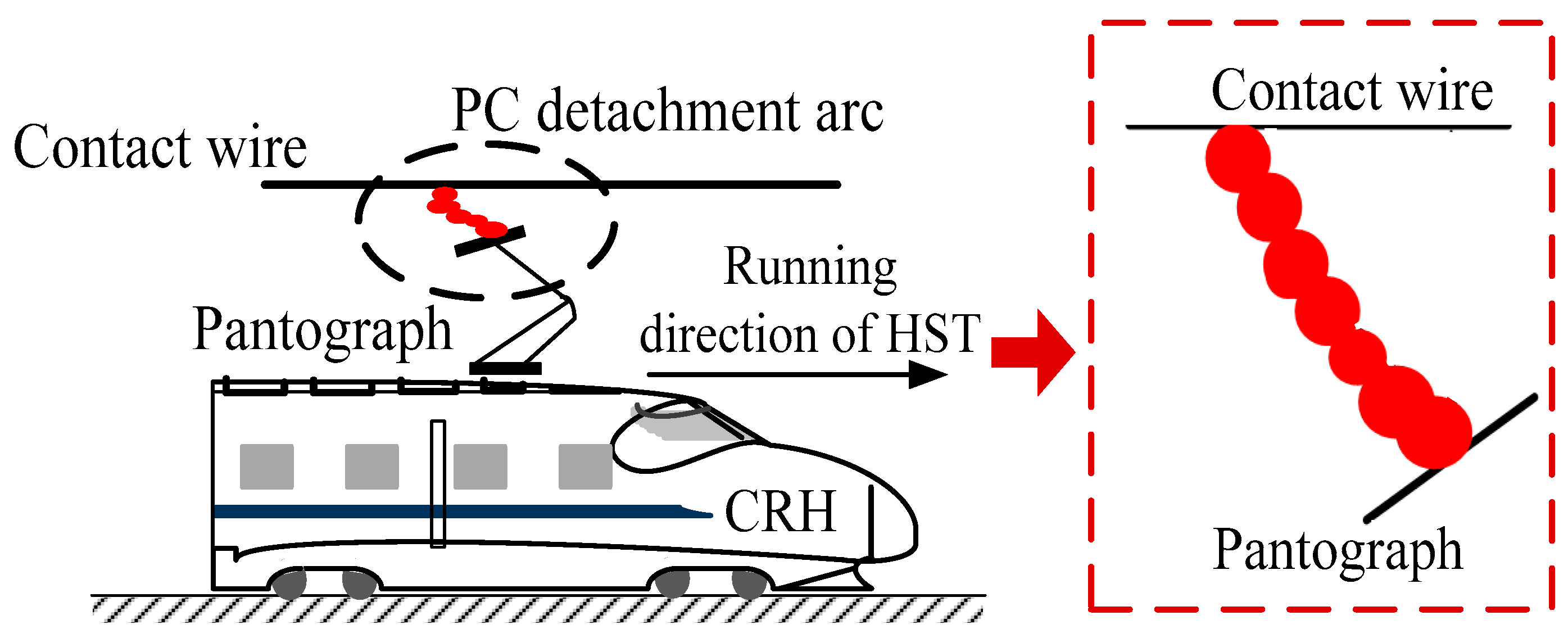
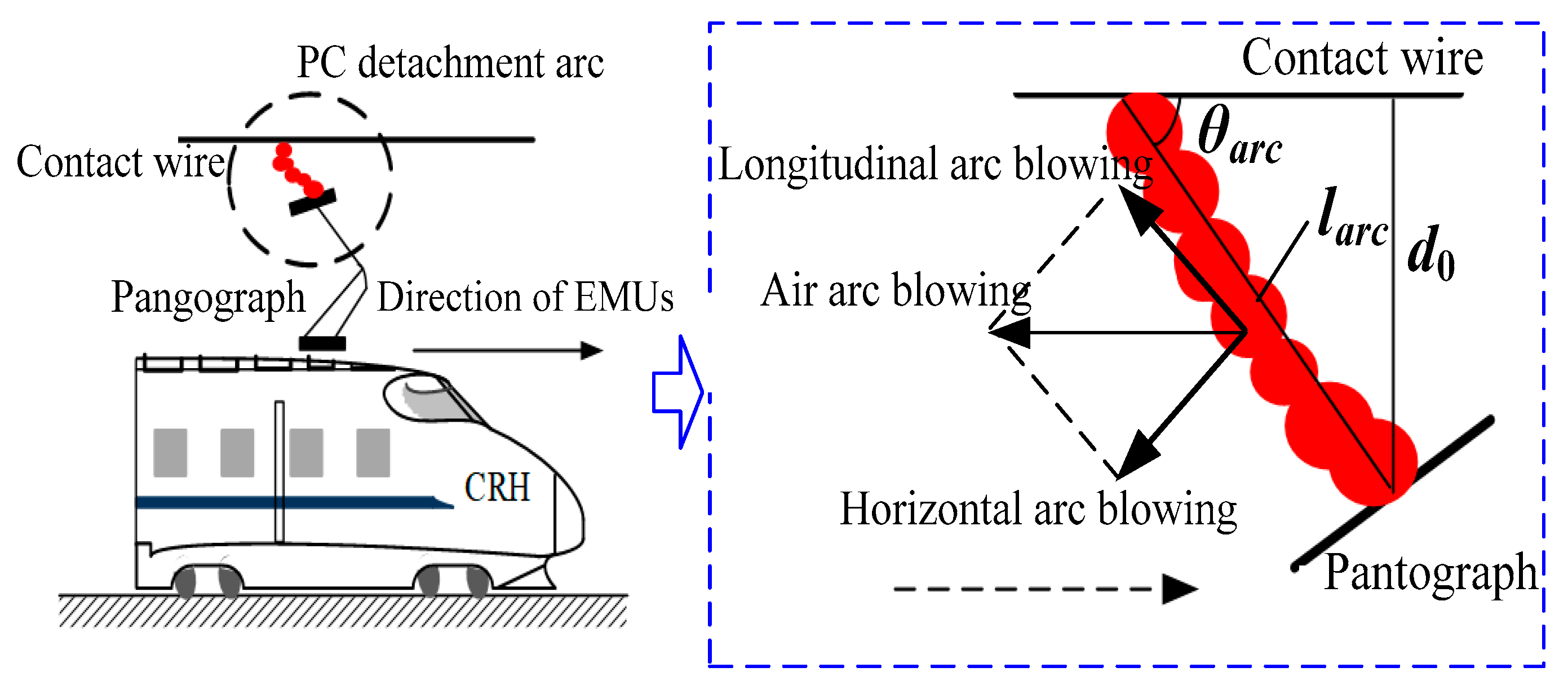
The black-box model is an important type of arc model based on the external electrical characteristics of the arc [6] and is developed from both the Cassie model [7] and the Mayr model [8]. The obtained results revealed that the Habedank model is further capable of improving the application range of the model by integrating the Cassie model and the Mayr model [9]. As is understood from Ref. [10], the Mayr model was utilized to examine the HSR-PC arc, and the effectiveness of the calculations was then proven by comparing the harmonics of the arc current. Since then, many investigators have attempted to extend the black-box models [9] and various arc models to analyze the arc characteristics, over-voltage, and electromagnetic interference (EMI) [1,11,12]. In Ref. [13], an improved arc model was proposed by taking the arc diameter as a function of the current, and the simulation accuracy of arc voltage was improved. In another work, the Habedank model was extended after introducing the vehicle speed to the arc dissipation power and voltage gradient [14]. A PC arc test platform was built and a Cassie–Mayr series model was modified according to test data [15]. Some scholars explored the role of the airflow field in arc power dissipation to optimize model power parameters [3]. As is seen in Ref. [16], the black-box arc model was further extended to examine the arc dynamic electrical characteristics. In some of the above PC arc models, the arc length is considered but represented by the detachment distance. Nevertheless, as shown in Figure 1, the arc inclines due to the air resistance and the arc length varies with the detachment distance during the operation of EMUs.
The distance or duration of PC detachment is one of the crucial factors of PC arc models, essentially obtained by PC dynamics simulation due to the lack of experimental conditions. The vertical displacement difference between the pantograph and the wire is generally considered as a measure of the occurrence of detachment [16]. Many PC dynamic coupling models have been developed to deflect of the contact force and the detachment trajectory [16,17]. Some investigators have proceeded with analyzing the influence rules of PC parameters on the detachment locations, durations, and intervals [18]. However, the dynamical simulations are not able to reflect the arc length.
The arc length is reflected in the movement of the arc shape. On the basis of discretizing the arc into many arc elements, the chain arc model is able to analyze the movement of the whole arc based on the force movement of each arc micro-element. So far, its application in the PC system includes the characteristics of arc extinction and the shape of arc motion in electric split-phase roads. In Ref. [19], the chain arc model was used to evaluate the arc shape motion of a lifting pantograph under the action of wind load. However, during PC detachment, the arc is also affected by pantograph movement and its shape characteristics are different from the lifting pantograph case. It is necessary to develop chain models for the detachment arc of running EMUs.
Research on the electrical effect of arcing mainly includes over-voltage, harmonics, and EMI [6,10]. Experimental testing and software simulation are the main investigation tools for transient over-voltages. Some researchers performed measurements on a PC test platform and concluded that arc voltage and arc current shapes are asymmetric [15]. Transient voltage simulations are generally conducted by employing the arc simulation model. The influence of vehicle speed on over-voltages of PCs and TBs was also examined, and a conclusion was drawn that the over-voltage peak value is proportional to the vehicle speed [20]. The TB voltages and currents were investigated in various grounding layouts and resistances and compared, focusing on different PC arcing scenarios [21]. A supercapacitor-based method was proposed to mitigate the over-voltage from the PC arcing and its effectiveness was verified by simulations [22]. However, transient over-voltages to vehicular grounding were not scrutinized in this scenario. Detachment arcs often occur in the operating line, and a methodical investigation of the interactions of multiple detachments is also needed.
To sum up, the following limitations exist in the current studies on the HSR PC arcing model and grounding electromagnetic transients.
(1)
The calculation of the dynamic characteristics of the arc length has not been examined by the chain arc model.
(2)
The dynamic characteristics of the actual arc length have not been taken into account, and the arc length is equivalent to the PC detachment distance in the former black-box arc models. However, the detachment distance is not able to fully characterize the arc length, and the over-voltages corresponding to different arc lengths are different.
(3)
The features of quenching and reigniting arcs have not been examined in depth. Their actions on the vehicular-grounding electromagnetic transients and the mutual influences of TB over-voltages of multiple arcs in a short time have not been studied.
As an extension of previous works, this paper attempts to implement extended PC arc modeling and electromagnetic transient analysis of the EMU vehicular-grounding system. A flowchart of various parts of this work is given in Figure 2, and three innovations are included in it.
(1)
The relationship between arc length and detachment distance is deduced, and an arc modeling scheme is proposed to study the influence of PC arcing on the TB over-voltages by taking into account the dynamic characteristics of arc length.
(2)
The characteristics of both arc extinguishing and arc ignition are thoroughly analyzed and their roles in the TB transient electromagnetic voltages are investigated, considering different influencing factors such as phase angle, excitation inductance, and vehicular protective grounding parameters.
(3)
The mutual effects of over-voltages of different detachments in a short time are methodically examined.
The remainder of this article is organized as follows. In Section 2, the arc development law and shape characteristics during the driving of EMUs are analyzed to obtain the dynamic characteristics of arc length by using the PC dynamics models and the PC chain arc model. Then, a black-box arc model considering the arc length characteristics is deduced to elaborate the vehicle-grid electrical power model for EMUs encountering multiple arcing scenarios in Section 3. On this basis, vehicular electromagnetic transient phenomena are simulated and analyzed, considering the scenarios of the arc extinction and arc reignition in Section 4, and multiple detachments in a short time are considered in Section 5. Conclusions are drawn in Section 6.

2. Modeling and Calculation of PC Detachment Arc Length Dynamic Characteristics

In this section, the finite element PC dynamic coupling model and chain arc model are appropriately constructed to simulate PC interaction in the presence of pantograph disturbance conditions. The PC system on the passenger-dedicated line from Beijing to Tianjin in China (marked as the Beijing–Tianjin line in this paper) is taken as an example; the parameters including detachment distance and detachment duration are calculated; and the arc length dynamic characteristics are deduced.

2.1. Calculation of PC Detachment Trajectory

The PC detachment trajectories are simulated on the basis of the PC dynamics model. The messenger wire and the contact wire are appropriately discretized by Euler–Bernoulli beam elements, the dropper is simulated by a nonlinear spring, and the positioning device is modeled as a lumped mass. The mass, stiffness, and damping matrices of all catenary elements are suitably assembled through the finite element method to arrive at the dynamic equation in Equation (1) [17].
M 1 y ¨ + C 1 y ˙ + K 1 y = F 1
where y represents the displacement vector, y ˙ and y ¨ , in order, are the velocity and global acceleration vectors, F1 is the external excitation vector, M1 is the catenary overall quality matrix, C1 is the damping matrix, and K1 is the stiffness matrix.
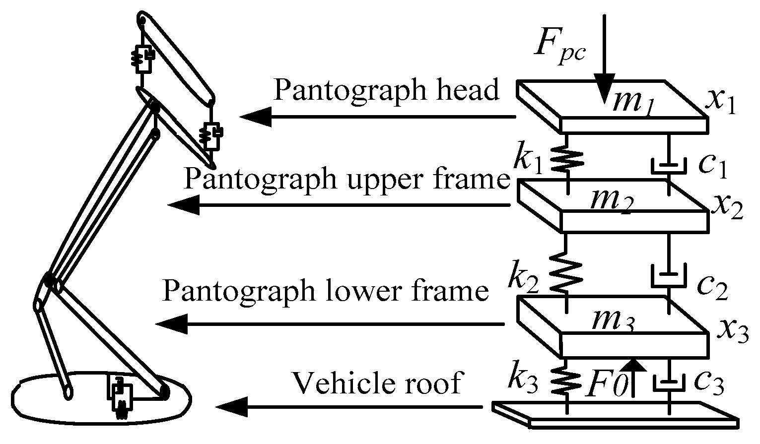
The pantograph’s vertical motion characteristics are essentially reflected by the three- mass-block linear model, as illustrated in Figure 3 [23]. The three mass blocks, respectively, represent the head, upper frame, and lower frame of the pantograph. The differential equations of motion are shown in Equation (2).
{ m 1 y ¨ 1 + c 1 ( x ˙ 1 x ˙ 2 ) + k 1 ( x 1 y 2 ) = F c ( t ) m 2 x ¨ 2 + c 1 ( x ˙ 2 x ˙ 1 ) + c 2 ( x ˙ 2 x ˙ 3 ) + k 1 ( x 2 x 1 ) + k 2 ( x 2 x 3 ) = 0 m 3 x ¨ 3 + c 2 ( x ¨ 3 x ¨ 2 ) + c 3 x ˙ 3 + k 2 ( x 3 x 2 ) + k 3 x 3 = F 0
where m1, m2, and m3 represent the weights of the three blocks; k1, k2, and k3 denote the stiffness coefficients of the three blocks; c1, c2, and c3 signify the damping coefficients of the three blocks; x1, x2 and x3 represent the vertical displacements of the three blocks; F0 is the pantograph static lifting force; and Fc denotes the pantograph contact force. The pantograph type used in the analyzed line is the DSA380 type. The penalty function method is adopted to describe the PC interaction. The rationality of this model was verified by comparison with the European standard EN50318-2002 [24], as explained in some detail in Ref. [25]. The aerodynamic effect and contact roughness are taken into account for the pantograph and the contact wire to simulate the detachment rule. The air force is exerted on m2, and the Newmark method is implemented for solving the dynamic equations in the time domain [26].
Accounting for the influences of pantograph aerodynamics and the contact wire irregularity, simulations are carried out to obtain the longitudinal displacements of the pantograph Lp(t) and the contact wire Lc(t) for different settings of vehicle speeds, wind speeds, and attack angles. As Lc(t) > Lp(t), the vertical displacement difference appears between the wire and the pantograph, the so-called detachment distance [16]. With the linear least-squares polynomial method, a single detachment distance curve is employed for obtaining the single detachment trajectory, fitted by [14,27]
d a r c ( t ) = i = 1 4 a i sin ( b i t + c i )
where ai, bi, and ci are fitting curve coefficients.

2.2. Chain Arc Modeling and Deduction

The PC arc is located in a complex electrical and electromagnetic environment, and the arc moves irregularly under the influence of electromagnetic force, air resistance, and wind load along with high supply voltage and fast pantograph running speed. The chain arc model can be employed to analyze the arc shape, but still, very little research has been devoted to the rational modeling of the PC chain arc. Only the pantograph lifting or lowering arc scenario has been researched and given attention [19]. However, when EMUs are in motion, the pantograph moves forward at high speed and the wind load on the arc microelement is also much higher than the lifting or dropping pantograph. Therefore, the shape of the detachment arc is different from the shape of lifting or dropping the pantograph.
In the chain arc model, the arc is discretized into several connected cylindrical arc micro-elements. Since the arc length is substantially greater than the arc diameter, the diameter of the arc element is set to a fixed value [28]. The barycentric coordinate of the i-th arc element is specified as Gi, and the vector direction of the arc element at the two roots of the arc is set vertically upwards. The arc is affected by the airflow thermal buoyancy, wind, and electromagnetic force, and the direction of the wind load is identical to that of the wind speed.
When the EMUs run at high speeds, the shape of the arc exerts three characteristics:
(1)
The bending or deformation of the arc exist, but it is not significant compared to the overall shape of the arc;
(2)
The influence of wind on the arc shape is mainly reflected in the overall arc shape;
(3)
The arc may be penetrated in some special cases, but its influence on the arc electrical characteristics and corresponding over-voltages is similar to the arc extinction.
Therefore, the following assumptions are made for force analyses of the problem [29]:
(1)
The arc element is a rigid body, the external forces only affect the overall arc shape, and the arc element does not bend or deform;
(2)
The wind load is a static force that acts uniformly on the surface of the element;
(3)
When the arc element moves, it is an impenetrable object.
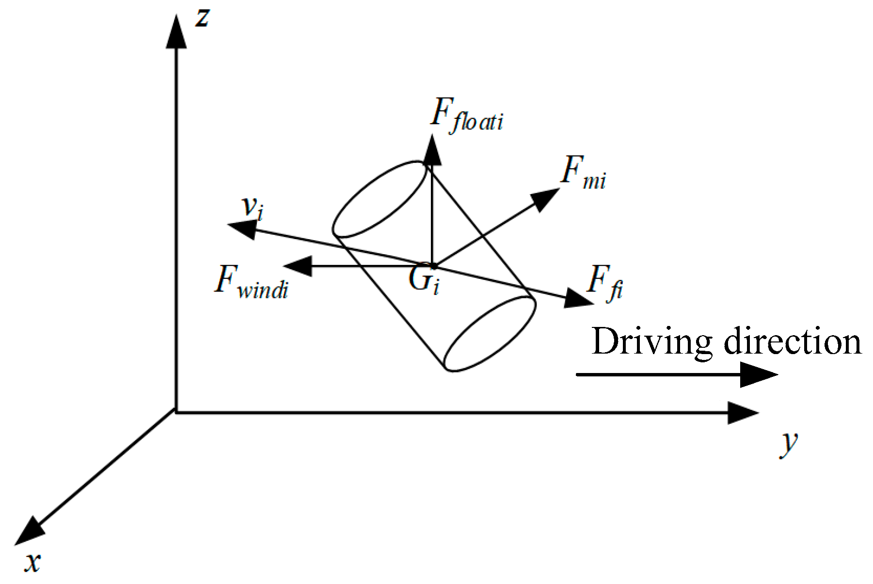
The force state of an arc element is seen in Figure 4. The driving direction of the EMUs is set as the positive direction of the y axis, and the contact wire is placed in the yoz plane. Fwindi represents the wind load, and its direction is opposite to the driving direction; Ffloati denotes the thermal buoyancy with a vertical upward direction; Ffi signifies the air obstructive force with the direction opposite to the velocity of the arc micro-element; Fmi is the magnetic force, and its direction depends on the current and magnetic field. The requirement of equilibrium of the applied forces leads to Equation (4).
F f l o a t i + F m i + F w i n d i + F f i = m i a i = 0
where mi and ai represent the mass and acceleration vector of the arc element. Each given force in Equation (4) is calculated based on the following relations:
{ d B = μ 4 π I d l × r r 3 F m i = l i ( I i × B i )
F f l o a t i = ( ρ 0 ρ ) g π r g 2 l i
F w i n d i = 0.93 r g l i ρ 0 v i 2
F f i = C R ρ 0 v i 2 r i l i
where μ represents the vacuum permeability; dl is the contact wire current element vector; r is the vector of the current element pointing to point P; li is the arc element length; Ii is the arc element current vector; ρ0 is the air density under standard atmospheric pressure, ρ0 = 1.295 kg/m3; ρ denotes air density at a high-temperature arc, ρ = 0.0221 kg/m3 [30]; g is the gravitational acceleration; rg represents the arc radius, rg = 0.0013I0.5; vw is the wind speed; CR is the air drag coefficient, CR = 1.18; and vi is the arc element motion velocity. Based on Equations (4)–(8), we can arrive at
v i = ( F w i n d i + F f l o a t i + F m i C R ρ 0 r g l i ) 1 2
Due to the different characteristics of the arc roots and the arc columns, the dynamic model of the arc roots needs a special deduction. The arc roots are located in the pantograph and the contact wire. On the pantograph side, the arc root is always kept on the pantograph, and its speed is identical to that of the pantograph. On the contact wire side, the arc root slides along the y-axis direction on the contact wire, and Ffloati is neglected in the vertical direction. Thus, the calculation formula of the arc root element at the contact wire side is expressed as
v i = ( F w i n d i + F m i C R ρ 0 r g l i ) 1 2
Both the arc column dynamic adjustment and the arc root current element jump correction are required in the deduction.
(1)
Arc column dynamic adjustment
To ensure the integrity and continuity of the chain model, the open circuit and short circuit between the arc elements are checked and corrected at each step. If the distance between two arc elements is greater than 3rg, a new arc element is inserted between the two elements and the number of micro-elements is reordered. If the distance between two micro-elements is less than 0.5rg, the two micro-elements are merged to eliminate the short-circuit arc elements and the number of elements is reordered.
(2)
Arc root current element jump correction
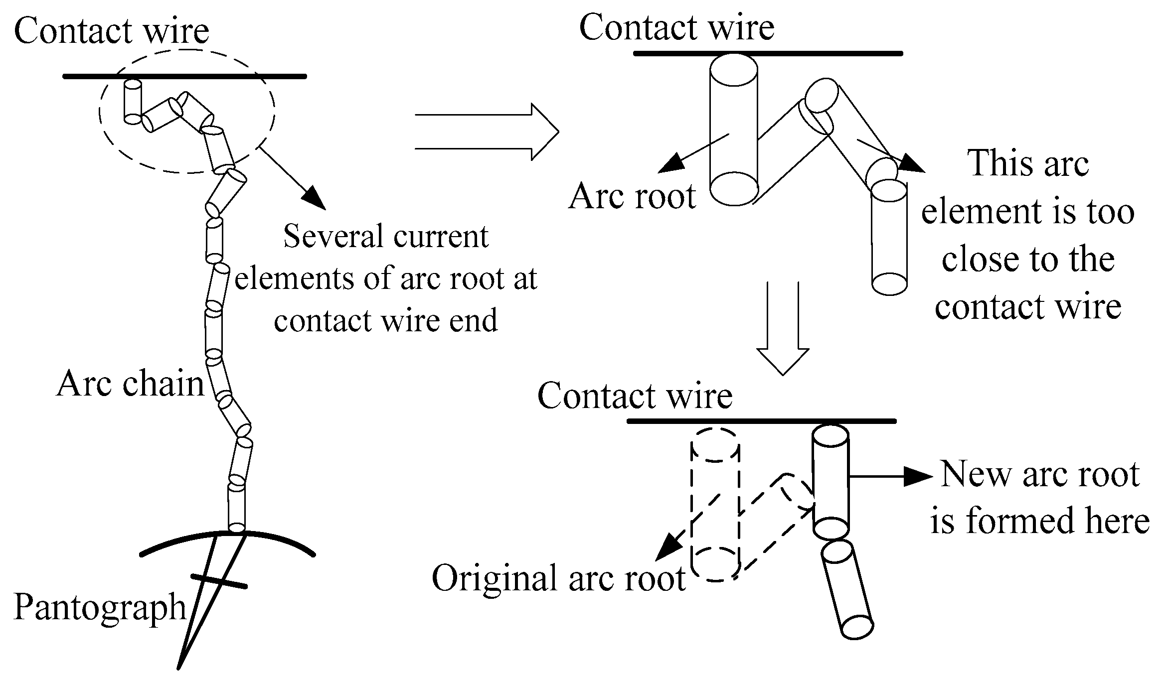
Since the arc root jumps over the contact wire in the arc, the jump correction shown in Figure 5 is given for the arc element near the contact wire. If the distance between the center of the arc element and the contact wire is less than half the length of the arc element, a new arc root is made at the arc element position.
Based on the above principles, the arc micro-element parameters, including force, running velocity, and position, are calculated based on the flowchart presented in Figure 6. First, the initial arc length, larc, the simulation time step, Δt, and the simulation time, t0, are set. At each time step, the magnetic induction intensity of each arc element is calculated based on the Biot–Savart law, and the velocity of the i-th arc element and the arc root element are solved by Equations (9) and (10). The calculated displacement at the next Δt updates the position of the arc element. In the next step, the length of all micro-elements is corrected and the arc root displacement in the contact wire is judged to obtain the new arc shape at the next Δt. Finally, the coordinate parameters of each element at each Δt are calculated to reflect the entire arc shape.

2.3. Analyses of PC Detachment Arc Motion Characteristics

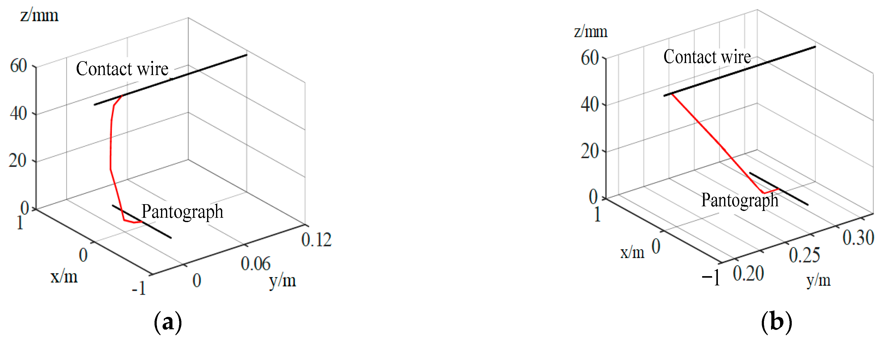
Based on the operating scenarios of the HSR PC system, the vehicle speed (v = 252 km/h), the wind speed (vw = 20 m/s), the attack angle (α = 40°), and the effective value of the catenary current (I0 = 300 A) are set; the calculation method of the detachment trajectory in Section 2.1 is introduced; and the maximum detachment distance is obtained as 64.5 mm. In the subsequent calculations, the detachment distance, d0, is set as 60 mm to better reflect the actual arc characteristics, and Δt is set equal to 0.4 ms. The shape of the arc is calculated in the initial arc phase (0~4 ms), and the corresponding shapes at 0.4 ms and 4.4 ms are presented in Figure 7.
Figure 8 exhibits the variable positions of the upper arc root with time, where the dotted line represents the theoretical result with the theoretical arc root speed of 15.82 m/s and the solid line denotes the calculated result. According to Figure 8, at the beginning of the arc, the arc is not stretched forward and the wind load causes the root elements of the upper arc to move in the negative y axis. As the pantograph moves forward, the entire arc is pulled forward by the lower arc root while the upper arc root elements continuously jump. New arc roots are constantly forming, resulting in specific features where the upper arc root movement speed is higher than the theoretical speed.
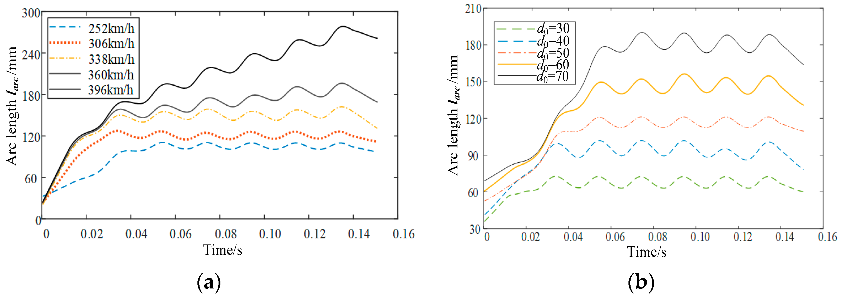
Figure 9 illustrates the calculated dynamic arc lengths in the presence of various v and d0 after filtering. Based on the previous studies [14,16], the effective value of the catenary current is set as I0 = 300 A, d0 = 50 mm for the calculation of Figure 9a and I0 = 300 A, v = 252 km/h for the calculation of Figure 9b. The wind load is the main force affecting larc. At the beginning of the arc, the movement of the arc is mainly driven by the wind load. As the arc enters the steady state, the arc presents an oblique linear shape, which is mainly affected by the motion of the pantograph. The arc length initially experiences an increasing trend and then maintains stable fluctuations. The obtained results reveal that the dynamic larc is noticeably affected by v and d0. The angle between the arc and the driving direction of EMUs (θarc) tends to be stable. Therefore, after the statistics of multiple model calculations, the relation of θarc as a function of v and d0 can be obtained.

3. Modeling of Vehicle-Grid Electric Power System Considering Arc Length Dynamic Characteristics

The transient over-voltage caused by the detachment arc directly affects the traction drive system and some electric devices of the vehicle, and the arc is closely connected to the pantograph, catenary, and EMUs. Considering this, the scenario of CRH2-type EMUs running on the Beijing–Tianjin line is considered as an example in a PC arc modeling scheme developed by considering the dynamic characteristics of the arc length. On this basis, the detailed vehicle-grid electric power model is built for describing the electromagnetic transient influences of various arcing scenarios using the MATLAB/Simulink 2016a software package. In addition, since the arc length is longer than the detachment distance and makes the arc extinguish easily, the influencing factors of quenching the arc are also analyzed based on the energy balance criterion and the dynamic changes in the arc length.

3.1. Extended Arc Model Considering Arc Length Dynamic Characteristics

As a pivotal parameter of the black-box arc model, the dissipated power is essentially affected by the arc length. The vibrational PC detachment distance (d0) is considered as the arc length (larc) in previous models [16]. Since d0 is not able to fully represent larc, based on the calculation results of the arc shape in Section 2, the relationship between larc and d0 is analyzed first.
According to PC arc current waveform investigations [31], the arc distorts the sinusoidal waveform and produces a transient during CZC, and the amplitude of the arc current will be very large due to the high traction voltage. In the simulation of the PC arc, the Mayr arc model is suitable for the CZC special region, whereas the Cassie arc model is suitable for high currents and low resistances [16]. The above two situations are both considered in the Habedank arc model [32]. Such a model essentially consists of a series associated with Mayr’s model given by Equation (11) and Cassie’s model provided by Equation (12). The entire arc conductance is derived by Equation (13).
d g m d t = 1 τ 1 ( i 2 P 0 g m )
d g c d t = 1 τ 2 ( i 2 u c 2 g c g c )
1 g = 1 g m + 1 g c
where g represents the instantaneous arc conductance; i denotes the arc current; P0 is the arc dissipation power; uc is the arc voltage gradient; gm and gc, in order, are the instantaneous conductance of the Mayr and Cassie parts; τ1 and τ2, in order, are the time constants of the Mayr and Cassie parts; and τ1 = τ2 = τ0gϖ, where ϖ represents a constant and τ0 is the initial time constant. In general, P0 and uc are time-variant factors in the whole arcing process and their expression formulas should be deduced.
The influence of the airflow field on the arc can be divided into horizontal and vertical arc blowings. Their basic principle is that the arc heats the gas unit from temperature T0 to the average arc temperature, Tc. The dissipation powers of unit arc length transverse and longitudinal blowings (i.e., PK1 and PK2) can be expressed by [3]
P K 1 = 0.81 k 1 i h ( v + 10 )
P K 2 = 0.183 i h v v + 10
where k1 is the related coefficient of P0 and v represents the arc motion velocity relative to the air value.
As illustrated in Figure 10, since the PC arc is blown laterally by the high-speed airflow, the arc is not completely perpendicular to the direction of the train running, and there is a certain angle between the axis of the arc and the moving direction of EMUs. The angle between the airflow direction and the axis of the arc (θarc) and the convective emission power per unit arc length (PK) is expressed in Equation (16) [3].
P K = 0.81 i ( v sin θ a r c + 10 ) + 0.183 i v cos θ a r c v cos θ a r c + 10
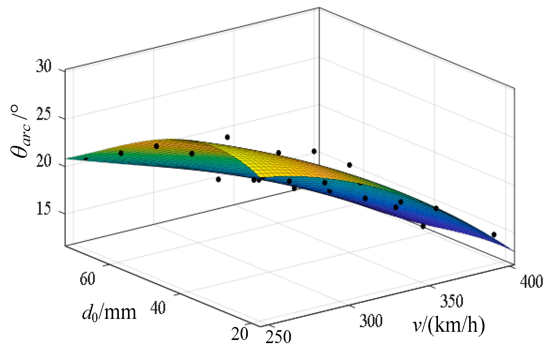
According to multiple calculation results of Section 2, the relations among θarc, vehicle speed (v), and detachment distance (d) can be fitted as
θ a r c ( v , d ) = p 0 + p 10 v + p 01 d + p 20 v 2 + p 11 v d + p 02 d 2 + p 21 v 2 d + p 12 v d 2 + p 03 d 3
where p0 = −19.55, p10 = 0.2959, p01 = 2.023, p20 = −0.0005489, p11 = −0.0076, p02 = −0.02262, p21 = 8.093 × 10⁻⁶, p12 = 3.403 × 10⁻⁵, and p03=7.606 × 10⁻⁵. Based on results of θarc under different d0 and v, a fitted curved surface is obtained as demonstrated in Figure 11.
Therefore, P0 can be derived by
P 0 = ( 0.81 k 1 i ( v sin θ a r c ( v , d ) + 10 ) + 0.183 i v cos θ a r c ( v , d ) v cos θ a r c ( v , d ) + 10 ) L a r c
Under the large AC arc current, the voltage gradient (uc) essentially depends on the arc column voltage gradient, and the ratio of uc and larc is approximately constant, such that [33]
u C = 15 L arc
By introducing the relational expression of θarc, v, and d in Equation (18), we obtain
u c = 15 × d ( t ) sin θ a r c ( v , d )
Based on Equations (18)–(20), the extended PC arc model based on Habedank’s equation is derived as
d g m d t = 1 τ 1 ( i 2 ( 0.81 k 1 i ( v sin θ a r c ( v , d ( t ) ) + 10 ) + 0.183 i v cos θ a r c ( v , d ( t ) ) v cos θ a r c ( v , d ( t ) ) + 10 ) × ( d ( t ) θ a r c ( v , d ( t ) ) ) g m )
d g c d t = 1 τ 2 ( i 2 ( 15 × d ( t ) θ a r c ( v , d ( t ) ) ) 2 g c g c )
{ 1 g = 1 g m + 1 g c d g m d t = 1 τ 0 g ϖ [ i 2 k g β ( 1.535 × 10 4 v 2 0.0505 v + 5.842 ) g m ] d g c d t = 1 τ 0 g ϖ [ i 2 ( 2.3025 × 10 3 v 2 0.7575 v + 87.63 ) 2 g c g c ]

3.2. Vehicle-Grid Electric Power Model

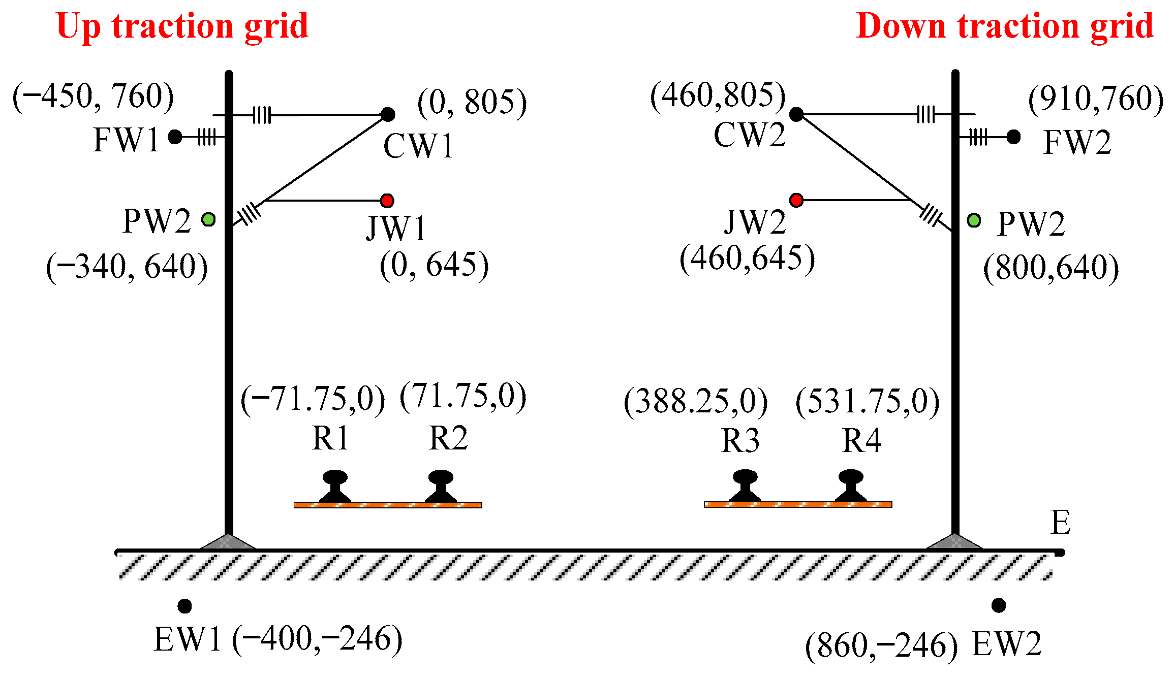
Auto-transformer (AT) modeling of the double-line fully parallel electric power grid and CRH2-type EMUs are included in the Beijing–Tianjin line. The vehicle-grid model includes a traction electric power part, a vehicular traction drive part, and a vehicular-grounding part. A cross view and coordinates of the electric grid conductors can be seen in Figure 12, where the contact wire, carrier cable, two rails, protective wire, integrated ground wire, and positive feeder in the up (down) traction grid, in order, are specified by JW1(JW2), CW1 (CW2), R1(R3), R2(R4), PW1(PW2), EW1(EW2), and FW1(FW2), and the ground is marked with E. The types of JW, CW, R, PW, and EW, in order, are CTS-150, JTMH-120, 60 kg, LBJLJ-120/20, and DH-70, and their equivalent radius values, in order, are 0.72 cm, 0.7 cm, 1.279 cm, 0.763 cm, and 0.437 cm. The position of the electric arc is set at a distance of 5 km from the post. The power grid model is appropriately constructed via a chain circuit and its parameters, involving self-impedance, mutual impedance, self-admittance, and mutual admittance, are deduced based on the Carson formula [34].
In the CRH2-type EMUs, two pantographs are installed on the roof of 02TB and 07TB and are connected by a high-voltage cable on the roof of the vehicle, as illustrated in Figure 13. The lengths of each terminal TB and each intermediate TB are 25.45 m and 24.5 m, respectively, while the distance between any two adjacent TBs is 0.5 m. During the drive of EMUs, the enhanced pantograph on 06TB receives traction currents from the catenary, which are transmitted to the vehicular transformers on 02TB and 06TB through the traction drive system. On the primary side of the transformer, the traction current enters the ground through the operational grounding system, the axis grounding terminal box, and the carbon brush. The protective grounding device is installed in 02TB, 03TB, 06TB, and 07TB. The grounding system parameters in CRH2-type EMUs are calculated and presented in Table 1.
Two traction drive units are included in the CRH2-type EMUs, each consisting of a pantograph, a transformer, and two converters. Each converter is connected with four motors. The AC-DC-AC variable, the frequency speed-regulation traction drive unit, is composed of a rectifier, an intermediate DC-link, and an inverter. The inverter and the traction motor are simplified as constant resistance to simplify the calculation. Dual four-quadrant pulse rectifiers are applied, and the electrical structure diagram and transient current control strategy are illustrated in Figure 14. In Figure 14 uN, iN, and uab are the secondary-side voltage, input current, and input voltage of the vehicular transformer, respectively, whereas uN, iN, and uab, in order, represent the corresponding electrical quantities of another rectifier, idc is the rectifier output current, and ud denotes the intermediate DC-link voltage.
The equations pertinent to the rectifier double closed-loop control, including voltage outer loop and current inner loop, are
{ I N 1 = K p ( U d * U d ) + 1 / T i ( U d * U d ) d t I N 2 * = 2 i d u d / U N p I N * = I N 1 * + I N 2 * u a b ( t ) = u N ( I N * R N sin ω t + ω L N I N * cos ω t ) G [ I N * sin ω t i N ]
where Kp represents the voltage proportional link constant, Ti denotes the voltage loop integral time constant, Unp is the transformer secondary-side voltage peak value, and G signifies the proportional coefficient of the current loop.

3.3. Model Validation

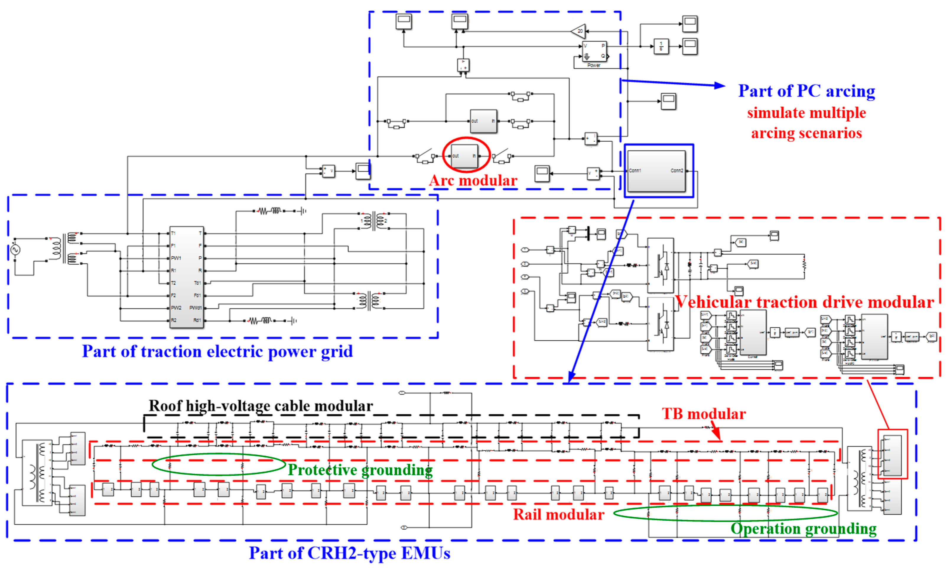
Based on the modeling procedure of Part A and Part B, the integrated equivalent vehicle-grid circuit model can be elaborated, as demonstrated in Figure 15. The case of v = 252 km/h and single detachment with d = 1.99 cm is analyzed, and the derived detachment trajectory fitting formula is Equation (25), where a0 = 6.264 × 10⁻⁴, a1 = 0.4448, a2 = 0.0280, a3 =−49.12, a4 = 279.6, a5 = −443.2, and T1 represents the arc starting time.
d a r c ( t ) = i = 1 6 a i × ( t T 1 ) i
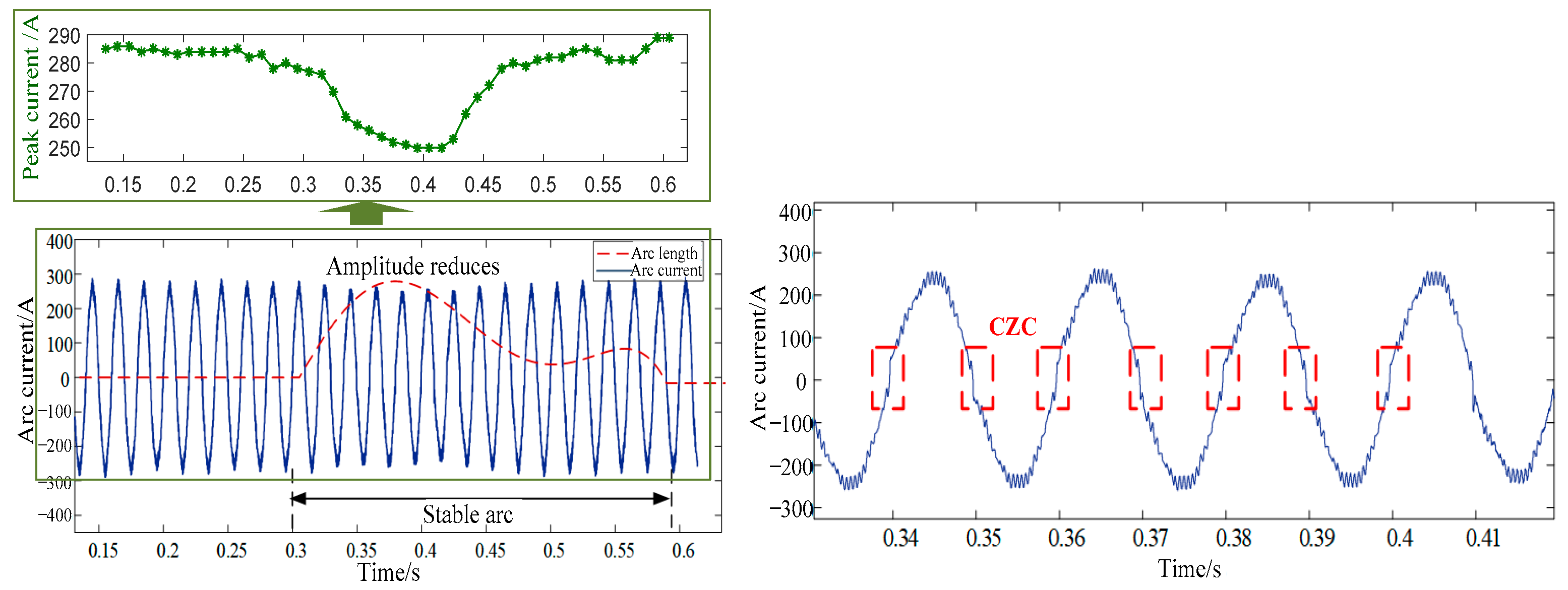
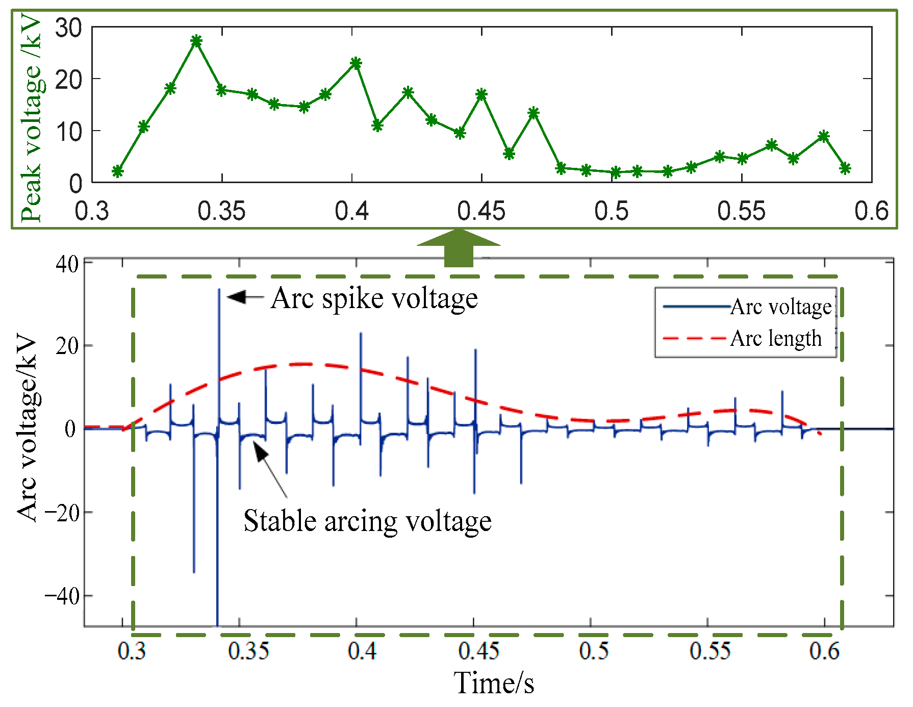
The simulated arc current waveform with varying arc lengths is presented in Figure 16, where the green curve is the peak current cycle values. The arc current amplitude at the time interval of [0.3 s, 0.45 s] is lower than other time intervals, such that it reaches the lowest value at t = 0.38 s. The variable trend of the arc current amplitude is opposite to the arc length (see the red curve), and the CZC phenomenon is also detectable. The above two characteristics match the arc current characteristics. The arc voltage waveform is appropriately simulated, as illustrated in Figure 17, where the green curve presents the peak voltage cycle values extracted. The maximum value of the stable arc appears at 0.38 s, and its amplitude is 14.35 kV. Furthermore, as seen from the green curve and red curve in Figure 17, the varying trend of the arc voltage spike value is positively correlated with the arc length. The spike appears during the CZC stage and the maximum spike value reaches more than 40 kV.
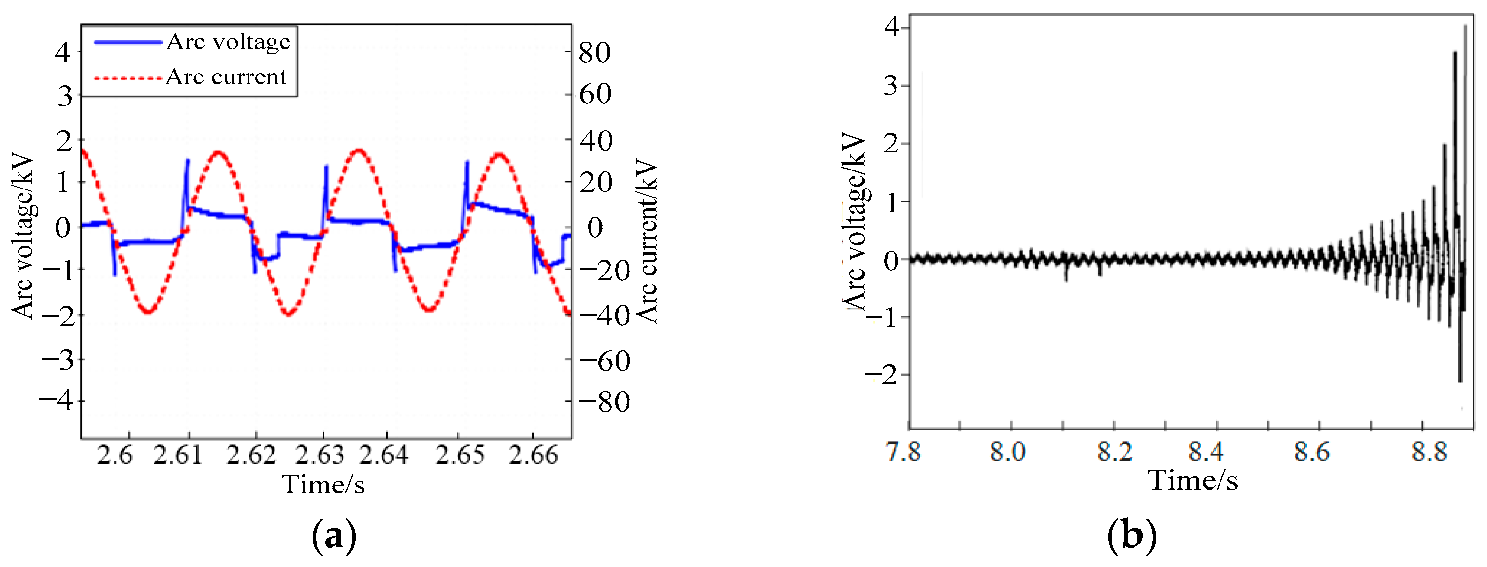
The method of verifying the similarity of waveform and electrical characteristics is employed here. If the simulated arc voltage and current waveforms are similar to the measured waveforms and their electrical characteristics are the same, it can be proven that the model is able to describe the PC arc phenomenon, and the growth of the arc parameter expansion is reasonable. The arc voltage was measured on the PC arc test platform (see Figure 18a) [35] and it is obvious that the arc voltage characteristics basically correspond to those presented in Figure 18. The waveform of the arc voltage in the arcing process of the dropping pantograph is also recorded in Figure 18b, which illustrates that the arc voltage growth gradually increases when the arc is continuously stretched [35]. This characteristic is consistent with the simulation results of Figure 17.
According to Ref. [36], the arc voltage and current waveforms are measured on the test platform, as illustrated in Figure 19. Before arriving at time t2, the pantograph is 3 mm below the contact wire. The pantograph moves increasingly closer to the contact wire until the air gap is broken and an arc occurs at t2~t3. The pantograph is in contact with the contact wire in the time interval t3~t4 and starts to move down at t4 until arc quenches at t5. The plotted results in Figure 19 reveal that the arc voltage decreases and the arc current increases with the decrease in the arc length in the range of t2~t3, while the arc voltage increases and the arc current decreases with the growth of the arc length in the t4~t5 interval. In Figure 19, the blue discrete point curve indicates that the peak voltage decreases with a shorter arc length, while the red discrete point curve reveals that the peak current lessens with a longer arc length. This relationship is consistent with the simulation results of the proposed model (see the green curves in Figure 16 and Figure 17).
To further prove the superiority of the proposed modeling method, the simulation results of Figure 16 and Figure 17 are also compared with those of previous models approximating the arc length as the detachment distance. In Ref. [16], the influence of the varying detachment distance on the arc voltages and arc currents is analyzed. By comparing the green curves of Figure 16 and Figure 17 with those of Ref. [16], the varying tendency of the arc voltage spike and peak current cycle value with the arc length or detachment distance is the same, but only the presented model matches with those of measured results for the feature of arc voltage spikes during CZC. This further illustrates the superiority of the proposed modeling method.

3.4. Calculations of the Arc Extinction and Arc Reignition Times

As the detachment arc is continuously stretched, the arc may be extinguished because the energy dissipated by the arc is greater than the energy input to the arc. Since the arc length affects the arc energy dissipation and arc ignition duration, the dynamic characteristics of the arc length are considered to calculate the times of arc extinction and arc reignition from the perspective of energy balance.
The dynamic energy balance equation of the PC arc is
d W Q d t = P i P o
where WQ, Pi, and P0, in order, represent the internal energy, input power, and dissipated power of the arc. As Pi < P0, WQ gradually decreases and the arc tends to extinguish. The calculation formulas of the dissipated energy W0(t) and the input energy Wi(t) are presented in Equations (27) and (28), where u(t) is the arc voltage and i(t) is the arc current.
W 0 = ( 0.81 k 1 i ( v sin θ a r c ( v , d ) + 10 ) + 0.183 i v cos θ a r c ( v , d ) v cos θ a r c ( v , d ) + 10 ) L a r c ( t ) d ( t )
W i ( t ) = u ( t ) i ( t ) d t
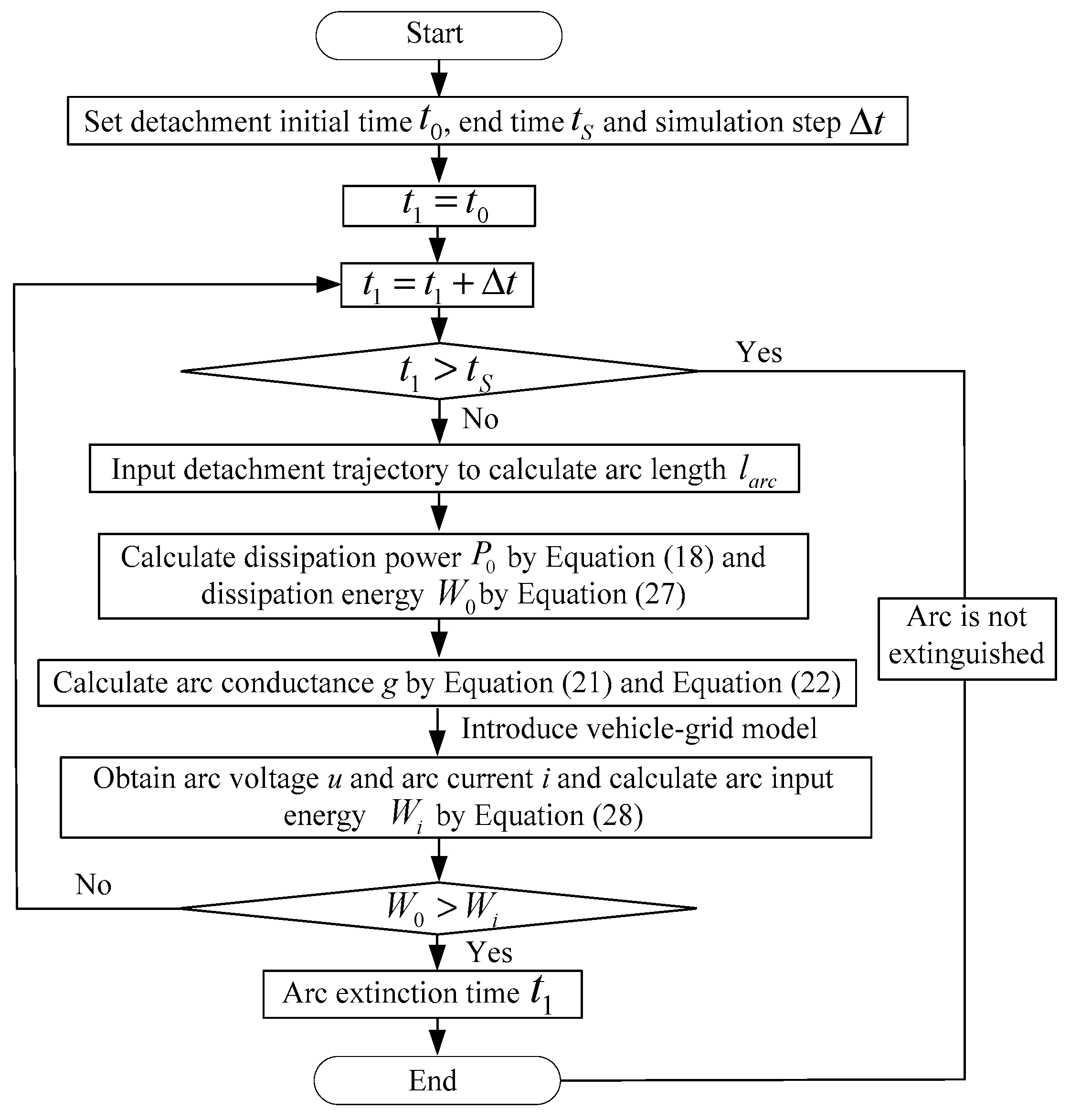
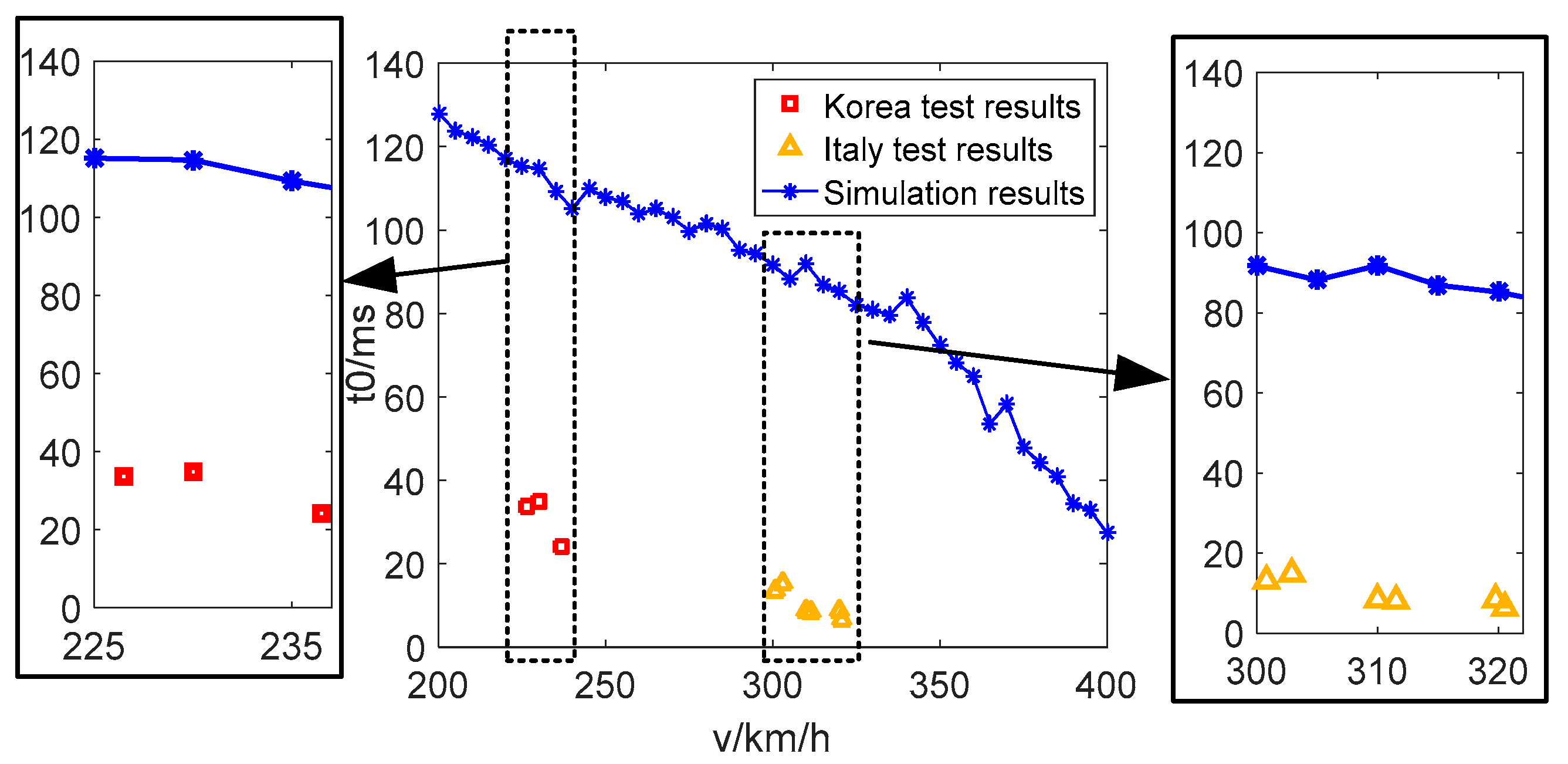
According to the arc extinction criterion for arc energy balance, the flowchart for deducing arc extinction and arc ignition times is given in Figure 20. The extinction time (t0) of typical detachment arcs at various speeds (v = 200~400 km/h) are considered, and t0 is simulated every 5 km/h. These prediction values are compared with the t0 detected for high-speed trains in Italy and South Korea [37,38]. As presented in Figure 21, the values of t0 are different for various test and simulation results due to the different traction electric power supply systems and PC structures used in various countries, but the trends of changes in t0 and v are the same. The comparison investigations not only prove that the arc is usually extinguished faster as v increases, but also further demonstrate that the simulation results match the test results.

4. Vehicular-Grounding Electromagnetic Transient Analyses Considering Arc Reignition

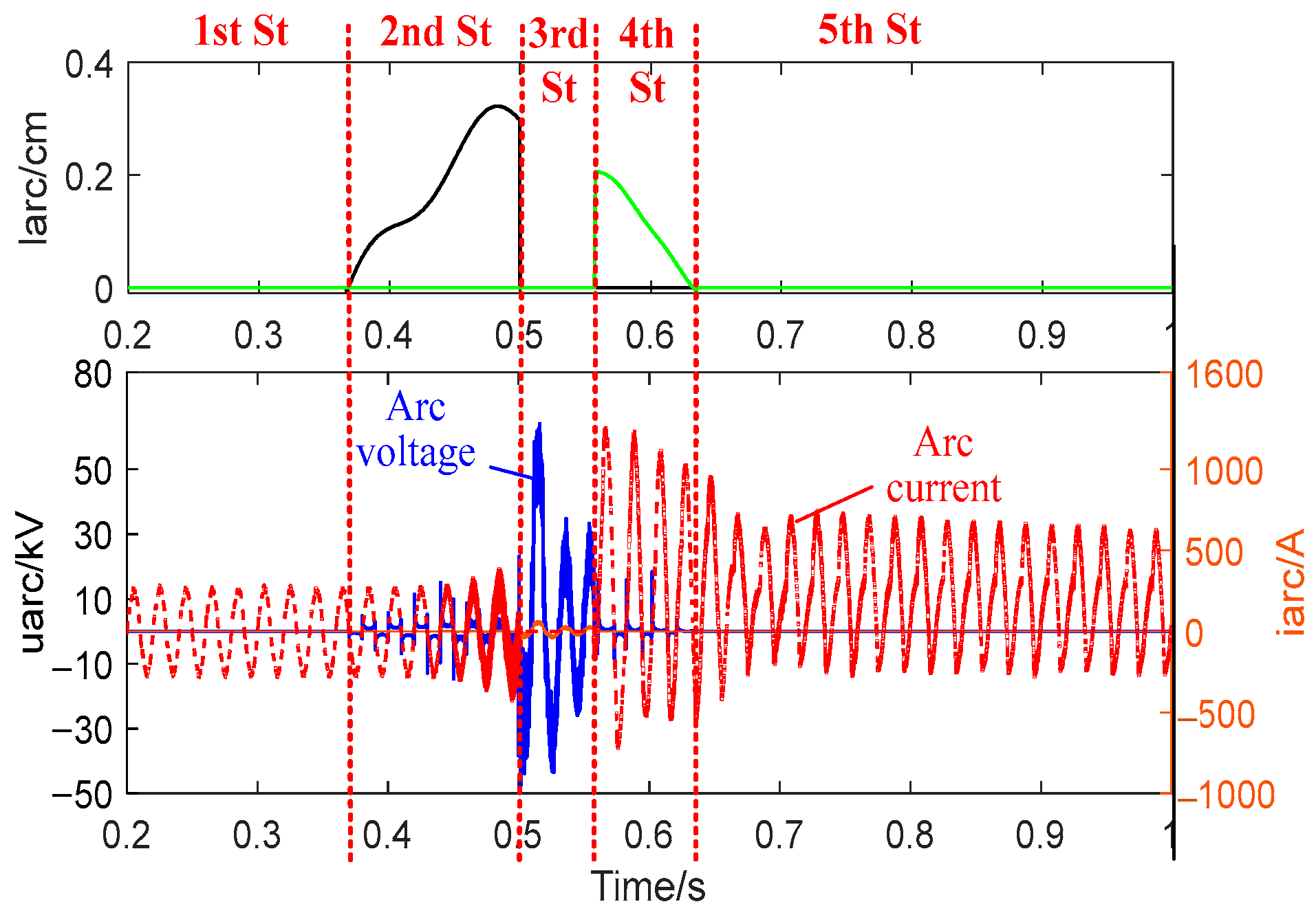
In this section, based on the established vehicle-grid electric power model, considering the dynamic characteristics of the arc length, the electromagnetic transients of vehicle grounding, which include arc extinction and arc reignition in the single detachment, are investigated. The roles of various factors, including instantaneous pantograph head (PH) phase, excitation inductance, and TB grounding parameters, on the TB transient voltages are methodically analyzed. According to the performed simulations, arc ignition occurs at 0.367 s and extinguishes at 0.5 s due to insufficient energy. Then, the PC air gap is broken down and the arc reignites at 0.56 s. At 0.635 s, the arc is completely extinguished as the PC contact is restored.
The arc electrical characteristic waveform along with the arc length is illustrated in Figure 22, where 1st St represents the stage before arcing; 2nd St denotes the first arcing process; 3rd St represents the arc extinguishing stage; 4th St signifies the second arcing process; and 5th St denotes the second arc extinguishing stage.
As presented in Figure 22, the arc voltage reaches its maximum value of 71 kV during the arc extinction stage and then gradually stabilizes at the catenary voltage level, during which the vehicular transformer inrush current generates. Before the inrush current decays to the normal value, if a normal arc occurs, the arc voltage amplitude will be increased, since the arc length (larc) at the moment of arc reignition (0.56 s) is shorter than that at the moment of arc extinction (0.5 s). In addition, the stable arc voltage spikes during arc reignition (0.56 to 0.635 s) are shorter than the first arc stage (0.367 to 0.5 s). When the EMUs recover electric power reception instantaneously at 0.56 s, the transformer is in the process of closing itself with the load, and inrush currents are generated. Therefore, the arc current reaches its maximum value of 1320 A in about 0.56 s and gradually attenuates to 800 A in four cycles. In the arc reignition stage, the arc current first reduces rapidly and then slows down. Based on these arcing stages, the TB transient voltage fluctuations are further analyzed.
In the CRH2-type EMUs, because the terminal voltages result from the superposition of traveling and reflected waves and the TB grounding device presents high impedance under the high-frequency conditions, higher over-voltage amplitude is observed in the terminal TBs and the grounded TB. Considering this issue, the transient voltage fluctuations of 01TB, 02TB, and 08TB (see Figure 13) are first examined. As is seen in Figure 23, the most violent oscillation and highest voltage values occur during 0.5~0.56 s (i.e., the arc extinguishing period). The TB voltage also experiences a process of increasing amplitude as the arc extends in the time interval of [0.367 s, 0.5 s].
Further, the various influencing factors with regard to the transient over-voltages are examined to explore the appropriate over-voltage suppression strategies.
First, the phase angle is considered. Different moments of arc extinguishing and the arc reignition can be regarded as the different moments or phases of opening and closing operations of the transformer, which lead to different degrees of excitation inrush currents and transient over-voltages. To reveal the effects of arc moments on the over-voltages, the initial PH phase (γ) is considered as an influencing factor. Under different γ values, the maximum voltage amplitude of 01TB (denoted by Utb1max) during the entire arc reignition stage is simulated, as the results are presented in Figure 24. The plotted results reveal that the influence is significant and Utbmax relatively remains at the highest value in the γ intervals of [90°, 110°] and [270°, 290°]. Although the duration of the over-voltages is very short, the highest amplitude reaches 4663 V when γ = 290°, higher than the electronic device withstand threshold in the relevant standard (i.e., 2000 V) [5]. Therefore, arc reignition must be suppressed.
Second, the excitation inductance is analyzed. The high-frequency oscillation of TB voltages during the transient process is directly related to the excitation inductance (Lm) of the vehicular transformer and the distributed capacitance of the high-voltage cable. Utbmax at different Lm values is also examined in Figure 24b. The demonstrated results indicate that a smaller Lm leads to a higher Utbmax due to the larger energy stored in the excitation inductance during the distributed capacitance charging process.
Third, the grounding parameters are examined. The distributions of Utbmax per TB in various layouts and impedances of the TB protective earth system are compared based on Figure 13. The layout patterns analyzed include the grounded 04~05TB, the layout of 01TB, 08TB, and grounded 04~05TB, the layout of grounded 02~07TB, and the all-ground TB layout. In the above layout, the grounding impedances of 02TB to 07TB are the same as those of CRH2-type EMUs, and each grounding impedance of 01TB and 08TB is 0.02 Ω. To reveal the effect of grounding inductance (L), since the ground arrangement remains the same as CRH2-type EMUs, four patterns (R = 0.02 Ω; R = 0.02 Ω and L = 14 μH; R = 0.5 Ω; and R = 0.5 Ω and L = 14 μH) are also selected. The above eight patterns exhibit the general range of the grounding layout and grounding impedance. The comparison results are provided in Figure 25.
The distribution trend in Figure 25 conforms to that of CRH2-type vehicles [20]. From the blue lines in Figure 25a, the peak values of terminal TBs are the highest if the terminal TBs and their adjacent ones are not grounded. This issue is because the terminal voltages are the result of the superposition of the traveling and reflected waves. The maximum value occurs in the layout of grounded 02~07TB rather than the layout of only intermediate grounded TBs. It is somehow inconsistent with the law that more ground channels lead to lower over-voltage. In addition, the profound impact of L can be observed in Figure 25b. The demonstrated results reveal that the TB voltages are remarkably affected by L, while the effect of R is quite negligible. The value of L can be decreased by shortening the grounding path, increasing the conductor size, using multiple parallel conductors, employing twisted or Litz wires, using low-inductance grounding materials, and optimizing the grounding layout.

5. Vehicular-Grounding Electromagnetic Transient Analyses Considering Arc Mutual Effects of Multiple Detachments

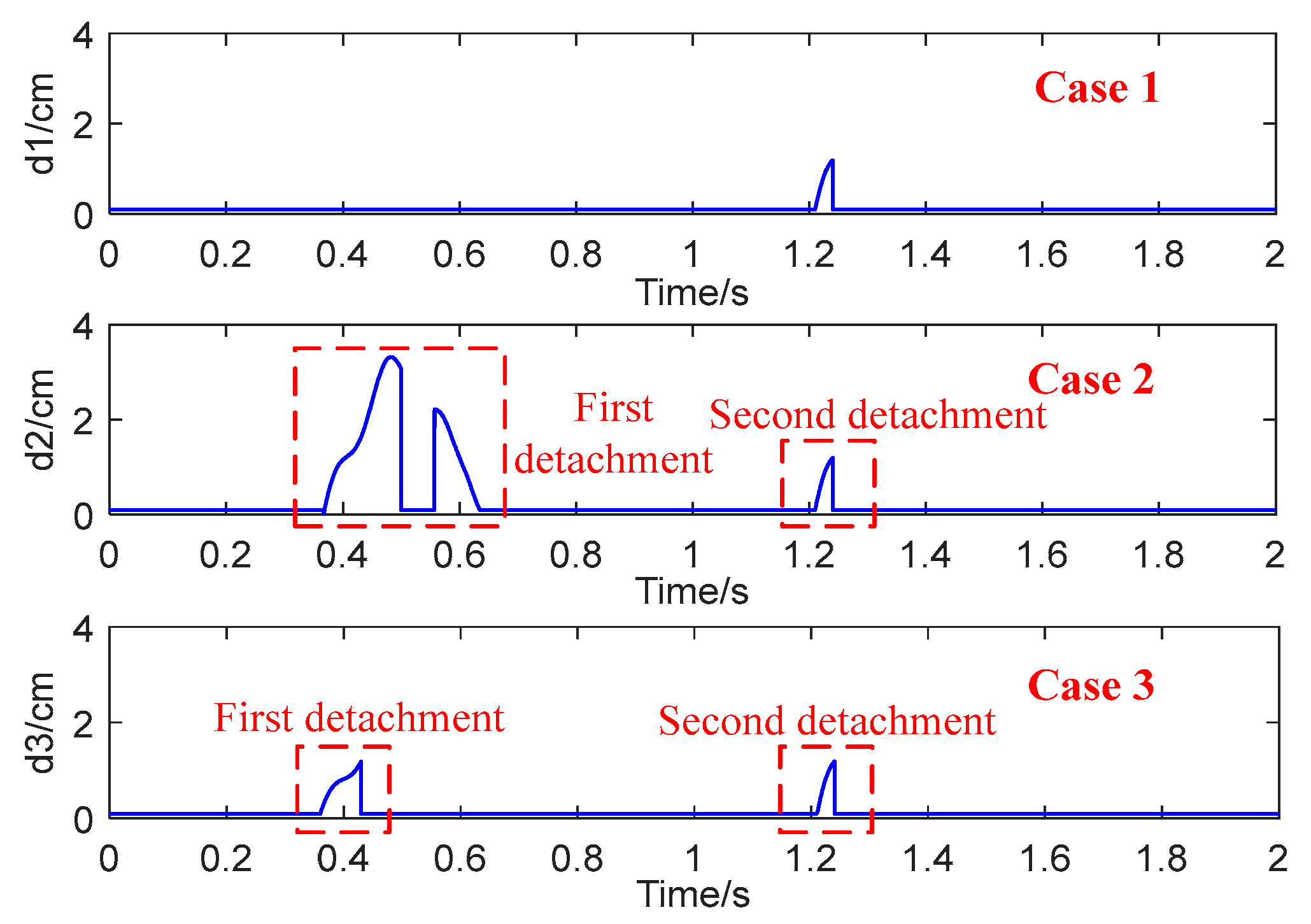
Several detachments are considered in a short time to analyze their mutual effects with respect to the transient over-voltages of the vehicular-grounding system. In the different calculation results of the detachment distance trajectory by the PC dynamic model, three cases with v = 306 km/h, vw = 20 m/s, and α = 40° are selected and their trajectories are demonstrated in Figure 26. A continuous detachment arc process is considered in the time interval of [1.21 s, 1.24 s] in all three cases, whereas two different detachments at the intervals of [0.367 s, 0.635 s] and [0.36 s, 0.43 s] are taken into account as the first detachments of Case 2 and Case 3, respectively. The first detachment in Case 2 contains one reigniting arc process, where the arc begins at 0.367 s, extinguishes at 0.5 s, reignites at 0.5575 s, and finally extinguishes at 0.635 s. The first detachment in Case 3 represents a continuous arcing process.
Three cases are simulated to analyze the arc voltage waveform from 1.21 to 1.24 s. Comparing the results of Case 1 with Cases 2 and 3 reveals the role of the reigniting arc and continuous arc in other detachments, respectively. As can be seen in Figure 27, compared with Case 1, the absolute value of the maximum arc spike voltage rises from 3392 V to 7640 V in the additional occurrence of arc reignition, and from 3392 V to 3447 V at different moments in the additional occurrence of continuous arcs. This shows that the arc reignition plays a vital role in the shape and amplitude of the arc voltage, whereas the effect of the continuous arc is much smaller.
The transient voltage fluctuations of each TB in the CRH2-type EMUs (see Figure 13) are further analyzed. At first, 01TB under arcing in the time interval of [1.21 s, 1.24 s] is considered and the transient fluctuations are compared in three cases to examine the effect of the superimposed over-voltage. As illustrated in Figure 28a, the additional occurrence of the arc reignition raises the maximum amplitude by 197.6 V and enables a much longer attenuation time. In comparison, according to the two waveforms presented in Figure 28b, under the role of an additional continuous arc, the maximum amplitude rises by only 65.8 V and the attenuation time is almost unaffected.
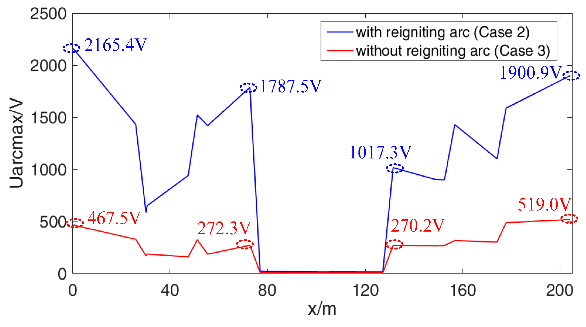
Next, the distributions of the maximum TB voltage (Utbmax) in the three cases are compared in Figure 29. The plotted results reveal that the arc reignition also has a more substantial impact on the distribution of Utbmax than the continuous arc. In addition, according to the electrical characteristics of vehicular grounding, it can be meaningfully observed from the comparison of Figure 27, Figure 28 and Figure 29 that the influence of the reigniting arc on the TB voltage is much lower than that of the arc voltage. Meanwhile, by comparing Figure 25 and Figure 29, it is found that the Utbmax only under the influence of the reigniting arc in another time interval (whose maximum is 568.8 V, as presented in Figure 29a) is much lower than Utbmax caused directly by the reigniting arc (more than 2 kV in Figure 25). The distributions of Utbmax in the entire simulation period of Case 2 and Case 3 are compared in Figure 30. Compared to the case without a reigniting arc (i.e., Case 3), the value of Utbmax = 2165.4 V in Case 2 illustrates that the reigniting arc rises the maximum value by 1646.4 V. This fact proves again that the occurrence probability of the reigniting arc should be suppressed.

6. Conclusions

As an advancement of previous works, this paper expands the modeling approach of PC detachment arcing and performs vehicular-grounding electromagnetic transient analyses of an HSR. The arc length dynamic characteristics are appropriately evaluated and introduced in the arc modeling. Based on the developed model, the TB transient over-voltages considering the arc extinction and arc reignition cases, as well as the mutual TB over-voltage influences of multiple arcings in a short time, are methodically examined.
(1)
The chain arc model is established to explore the arc shape changing principle under the multi-field coupling influences. The jump of the upper arc root essentially explains the reason why the arc length will not continue to increase. Additionally, the arc length grows with the increasing vehicle speed and detachment distance.
(2)
On the basis of deducing the dynamic relationship between the detachment distance and arc length, the arc length dynamic characteristics are introduced and an arc modeling scheme is proposed to elaborate the vehicle-grid electric power model under various detachment arcing scenarios. The rationality and correctness of the proposed modeling approach is then verified by comparing the simulated results with those of the measured results and the previous model.
(3)
During arc extinction and arc reignition, the inrush current results in much more severe TB over-voltages. The influence of the instantaneous PH phase is significant, covering nearly 180°. A smaller excitation inductance results in higher over-voltages due to the larger stored energy in the charging process of roof cable distribution capacitance. For the multiple detachments, the superposition of over-voltages is remarkable, where the effect of the arc reignition is much higher than that of the continuous arc.
The relation between arc power and arc temperature can be investigated in the near future to establish the arc magnetic fluid model and to expand the formula of dissipated power and voltage gradient further. Also, focusing on the resonance, developing more refined inverter and traction motor models, and examining the effect of arcing on motor characteristics will be the focus of future works.

Author Contributions

Conceptualization, methodology, validation, formal analysis, investigation, writing, data curation, and project administration: K.H.; resources, review and editing: D.S. All authors have read and agreed to the published version of the manuscript.

Funding

This research was funded by the National Natural Science Foundation of China, grant number 52202450, and the Fundamental Research Funds for the Central Universities, grant numbers 22120220462 and 22120230110.

Data Availability Statement

The original contributions presented in the study are included in the article, further inquiries can be directed to the corresponding author.

Acknowledgments

We would like to thank the National Maglev Transportation Engineering R&D Center of Tongji University, the Electromagnetic Compatibility Laboratory group of Southwest Jiaotong University, and China Railways Rolling Stock Corporation Qingdao Sifang Co., Ltd., for their technical support and necessary data in the establishment, verification, and analyses of the proposed modeling scheme.

Conflicts of Interest

Author Dongdong Su is employed by the company PowerChina Huadong Engineering Corporation Ltd. The remaining authors declare that the research was conducted in the absence of any commercial or financial relationships that could be construed as a potential conflict of interest.

References

  1. Midya, S.; Bormann, D.; Schutte, T.; Thottappillil, R. Pantograph arcing in electrified railways-mechanism and influence of various parameters-part II: With AC traction power supply. IEEE Trans. Power Deliv. 2009, 24, 1940–1950. [Google Scholar] [CrossRef]
  2. Midya, S.; Bormann, D.; Schutte, T.; Thottappillil, R. DC component from pantograph arcing in AC traction system-influencing parameters, impact, and mitigation techniques. IEEE Trans. Power Deliv. 2011, 53, 18–27. [Google Scholar] [CrossRef]
  3. Chen, X.; Cao, B.; Liu, Y.; Gao, G.; Wu, G. Dynamic model of pantograph-catenary arc of train in high speed airflow field. High Volt. Eng. 2016, 42, 3593–3600. (In Chinese) [Google Scholar]
  4. Wu, J.; Xiao, S.; Zhang, C.; Luo, Y.; Rao, Y.; Gao, G.; Wu, G.; Sykulski, J.K. Multiobjective optimization of the integrated grounding system for high-speed trains by balancing train body current and overvoltage. IEEE Trans. Transp. Electrif. 2021, 7, 1712–1723. [Google Scholar] [CrossRef]
  5. National Standardization Administration. GB/T3805-2008Extra Low Voltage (ELV) Limit; China Standards Press: Beijing, China, 2011.
  6. Xu, C.; Chen, Z.; Cheng, E.; Wang, X.; Ho, H.F. A supercapacitor-based method to mitigate overvoltage and recycle the energy of pantograph arcing in the high speed railway. Energies 2019, 12, 1214. [Google Scholar] [CrossRef]
  7. Habedank, U. On the mathematical description of arc behaviour in the vicinity of current zero. Etz Arch. 1988, 11, 339–343. [Google Scholar]
  8. Mayr, O. Contribution to the theory of static and dynamic arcs. Arch. Elektrotech. 1943, 37, 589–608. [Google Scholar]
  9. Guardado, J.L.; Maximov, S.G.; Melgoza, E.; Naredo, J.L.; Moreno, P. An improved arc model before current zero based on the combined Mayr and Cassie arc models. IEEE Trans. Power Deliv. 2005, 20, 138–142. [Google Scholar] [CrossRef]
  10. Liu, Y.; Chang, G.W.; Huang, H.M. Mayr’s equation-based model for pantograph arc of high-speed railway traction system. IEEE Trans. Power Deliv. 2010, 25, 2025–2027. [Google Scholar] [CrossRef]
  11. Ma, L.; Wen, Y.; Marvin, A.; Karadimou, E.; Armstrong, R.; Cao, H. A novel method for calculating the radiated disturbance from pantograph arcing in high-speed railway. IEEE Trans. Veh. Technol. 2017, 66, 8734–8745. [Google Scholar] [CrossRef]
  12. Yang, Y.; Cao, H.; Zhang, M.; Su, Z.; Hu, M.; Jin, M.; Liu, S. Research on the influence of pantograph catenary contact loss arcs and zero-crossing stage on electromagnetic disturbance in high-speed railway. Energies 2024, 17, 138. [Google Scholar] [CrossRef]
  13. Khakpour, A.; Franke, S.; Gortschakow, S.; Uhrlandt, D.; Methling, R.; Weltmann, K.D. An improved arc model based on the arc diameter. IEEE Trans. Power Deliv. 2016, 31, 1335–1341. [Google Scholar] [CrossRef]
  14. Wang, Y.; Liu, Z.; Mu, X.; Huang, K.; Wang, H.; Gao, S. An extended Habedank’s equation-based EMTP model of pantograph arcing considering pantograph-catenary interactions and train speeds. IEEE Trans. Power Deliv. 2016, 31, 1186–1194. [Google Scholar] [CrossRef]
  15. Wang, W. Study of Dynamic Characteristic for High Speed Railway Pantograph Arcing. Ph.D. Thesis, Southwest Jiaotong University, Chengdu, China, 2013. [Google Scholar]
  16. Liu, Z.; Zhou, H.; Huang, K.; Song, Y.; Zheng, Z.; Cheng, Y. Extended black-Box model of pantograph-catenary detachment arc considering pantograph-catenary dynamics in electrified railway. IEEE Trans. Ind. Appl. 2019, 55, 776–785. [Google Scholar] [CrossRef]
  17. Xu, Z.; Song, Y.; Liu, Z. Effective measures to improve current collection quality for double pantographs and catenary based on wave propagation analysis. IEEE Trans. Veh. Technol. 2020, 69, 6299–6309. [Google Scholar] [CrossRef]
  18. Zhang, J.; Liu, W.; Zhang, Z. Study on characteristics location of pantograph-catenary contact force signal based on wavelet transform. IEEE Trans. Instrum. Meas. 2018, 68, 402–411. [Google Scholar] [CrossRef]
  19. Wang, Y.; Liu, Z.; Gao, S. Dynamic calculations of high-speed EMU rising and dropping pantograph arc considering effect of wind load. Proc. CSU-EPSA 2016, 28, 5–9, 23. (In Chinese) [Google Scholar]
  20. Huang, K.; Lin, G.; Liu, Z.; Yang, Y. Research on transient over-voltages of high-speed train passing articulated split-section insulator. IEEE Trans. Transp. Electrif. 2023, 9, 1664–1682. [Google Scholar] [CrossRef]
  21. Huang, K.; Liu, Z.; Zhu, F.; Deng, Y. Grounding behavior and optimization analysis of electric multiple units. IEEE Trans. Transp. Electrif. 2021, 7, 240–255. [Google Scholar] [CrossRef]
  22. Mariscotti, A. The electrical behaviour of railway pantograph arcs. Energies 2023, 16, 1465. [Google Scholar] [CrossRef]
  23. Zhou, H.; Liu, Z.; Xiong, J.; Duan, F. Characteristic analysis of pantograph-catenary detachment arc based on double- pantograph-catenary dynamics in electrified railways. IET Electr. Syst. Transp. 2022, 12, 238–250. [Google Scholar] [CrossRef]
  24. EN50318-2002; Railway Application-Current Collection Systems-Validation of Simulation of The Dynamic Interaction between Pantograph and Overhead Contact Line. British Standards Institute: London, UK, 2002.
  25. Lu, X.; Liu, Z.; Song, Y.; Wang, H.; Zhang, J.; Wang, Y. Estimator-based multiobjective robust control strategy for an active pantograph in high-speed railways. Proc. Inst. Mech. Eng. Part F-J. Rail Rapid Transit 2017, 232, 1064–1077. [Google Scholar] [CrossRef]
  26. Song, Y.; Liu, Z.; Wang, H.; Lu, X.; Zhang, J. Nonlinear modelling of high-speed catenary based on analytical expressions of cable and truss elements. Veh. Syst. Dyn. 2015, 53, 1455–1479. [Google Scholar] [CrossRef]
  27. Anghel, S.R.; Miklos, C.; Averseng, J.; Tirian, G.O. Control system for catenary-pantograph dynamic interaction force. In Proceedings of the International Joint Conference on Computational Cybernetics and Technical Informatics, Timisoara, Romania, 27–29 May 2010; pp. 181–186. [Google Scholar]
  28. Sima, W.; Tan, W.; Yang, Q.; Luo, B.; Li, L. Long AC arc movement model for parallel gap lighting protection device with consideration of thermal buoyancy and magnetic force. Proc. CSEE 2011, 31, 138–145. (In Chinese) [Google Scholar]
  29. Ji, L.; Chen, D.; Liu, Y.; Li, X.; Niu, C. Simulation of the interruption process of low voltage circuit breaker using dynamic mathematic arc model. Proc. CSEE 2009, 29, 107–113. (In Chinese) [Google Scholar]
  30. Xing, J.; Li, Q.; Cong, H.; Li, J.; Chen, Q. Physical mechanism and simulation method of the arc root jumping and arc length variation of the secondary arcs with long-distance transmission lines. Trans. China Electrotech. Soc. 2016, 31, 90–98. [Google Scholar]
  31. Buhrkall, L. DC components due to ice on the overhead contact wire of AC electrified railways. Electrische Bahnen 2005, 103, 380–389. [Google Scholar]
  32. Ohtaka, T.; Kertesz, V. Novel black-box arc model validated by highvoltage circuit breaker testing. IEEE Trans. Power Deliv. 2017, 33, 1835–1844. [Google Scholar] [CrossRef]
  33. Swierczynski, B.; Gonzalez, J.J.; Teulet, P.; Freton, P.; Gleizes, A. Advances in low-voltage circuit breaker modelling. J. Phys. D Appl. Phys. 2004, 37, 595–609. [Google Scholar] [CrossRef]
  34. Carson, J.R. Wave propagation in overhead wires with ground return. Bell Syst. Tech. J. 1926, 5, 339–359. [Google Scholar] [CrossRef]
  35. Wei, W.; Zhang, T.; Gao, G.; Wu, G. Influences of pantograph-catenary arc on electrical characteristics of a traction drive system. High Volt. Eng. 2018, 44, 1589–1597. (In Chinese) [Google Scholar]
  36. Wei, W.; Wu, J.; Gao, G.; Gu, Z.; Liu, X.; Zhu, G.; Wu, G. Study on pantograph arcing in a laboratory simulation system by high-speed photography. IEEE Trans. Plasma Sci. 2016, 44, 2438–2445. [Google Scholar] [CrossRef]
  37. Bruno, O.; Landi, A.; Papi, M. Phototube sensor for monitoring the quality of current collection on overhead electrified railways. Proc. Inst. Mech. Eng. Part F J. Rail Rapid Transit 2001, 3, 231–241. [Google Scholar] [CrossRef]
  38. Park, Y.; Lee, K.; Kwon, S. Analysis of percentage of arcing between pantograph and overhead contact line as a function of duration of arc. Trans. Korean Inst. Electr. Eng. 2014, 6, 855–859. [Google Scholar] [CrossRef]
Figure 1. Schematic representation of the PC detachment arcing along with running EMUs.
Energies 17 01512 g001
Figure 2. Flowchart of various parts of the conducted work.
Energies 17 01512 g002
Figure 3. Schematic representation of the three-mass pantograph model.
Energies 17 01512 g003
Figure 4. Free-body diagram of an arc micro-element.
Energies 17 01512 g004
Figure 5. PC arc root jumping form at the contact wire end.
Energies 17 01512 g005
Figure 6. Calculation procedure of the chain arc model.
Energies 17 01512 g006
Figure 7. Calculated PC detachment arc shapes at two times. (a) 0.4 ms; (b) 4.4 ms.
Energies 17 01512 g007
Figure 8. Position variation of the upper arc root.
Energies 17 01512 g008
Figure 9. Prediction of the dynamic arc lengths (larc) in the presence of various vehicle speeds (v) and detachment distances (d0). (a) Effect of v; (b) effect of d0.
Energies 17 01512 g009
Figure 10. Diagram of the airflow arc blowing.
Energies 17 01512 g010
Figure 11. Fitted curve of θarc.
Energies 17 01512 g011
Figure 12. A cross view and coordinates of the power grid conductors (unit: cm).
Energies 17 01512 g012
Figure 13. Electrical structure and axle distribution of various TBs in the CRH2-type EMUs.
Energies 17 01512 g013
Figure 14. Diagrams of the pulse rectifier and the transient current control structures.
Energies 17 01512 g014
Figure 15. Vehicle-grid equivalent circuit model.
Energies 17 01512 g015
Figure 16. The simulated arc current waveforms and the corresponding amplitude with varying arc lengths.
Energies 17 01512 g016
Figure 17. The simulated arc voltage waveform with varying arc length.
Energies 17 01512 g017
Figure 18. Measured arc electrical waveform in different scenarios in different experiments. (a) Arc voltage and arc current in Ref. [1] (arc length is stable); (b) arc voltage in Ref. [35] (arc is continuously stretched).
Energies 17 01512 g018
Figure 19. Arc test results under different stages of PC interaction in Ref. [36].
Energies 17 01512 g019
Figure 20. Flow chart for judging whether the arc is extinguished according to model simulation.
Energies 17 01512 g020
Figure 21. Comparison of the arc extinction times in the presence of various vehicle speeds.
Energies 17 01512 g021
Figure 22. Waveforms of the arc length, arc voltage, and arc current.
Energies 17 01512 g022
Figure 23. Voltage waveforms of 01TB, 02TB, and 08TB along with the varying arc length: (a) 01TB; (b) 02TB; (c) 03TB.
Energies 17 01512 g023
Figure 24. Maximal over-voltages of 01TB along with different phases (γ) and excitation inductance (Lm) during the reigniting arc stage: (a) effect of γ; (b) effect of Lm.
Energies 17 01512 g024
Figure 25. TB over-voltage distributions under different TB grounding parameters during the reigniting arc stage: (a) different grounding layouts; (b) different grounding impedances.
Energies 17 01512 g025
Figure 26. Detachment distance trajectory of three understudied cases as v = 306 km/h in the time interval of [0 s, 2 s].
Energies 17 01512 g026
Figure 27. Arc voltage waveform at 1.21~1.24 s for the understudied three cases: (a) comparison between Case 1 and Case 2; (b) comparison between Case 1 and Case 3.
Energies 17 01512 g027
Figure 28. Voltage waveforms of 01TB during the arc at 1.21~1.24 s for the three understudied cases: (a) comparison between Case 1 and Case 2; (b) comparison between Case 1 and Case 3.
Energies 17 01512 g028
Figure 29. TB over-voltage distributions during the arc at 1.21~1.24 s for the three understudied cases: (a) comparison between Case 1 and Case 2; (b) comparison between Case 1 and Case 3.
Energies 17 01512 g029
Figure 30. TB over-voltage distributions in the total quantum time for the three understudied cases.
Energies 17 01512 g030
Table 1. Model parameters of CRH2-type EMUs.
ParameterValueParameterValueParameterValue
Equivalent resistance of high-voltage cable0.014 mΩ/mEquivalent inductance of high-voltage cable0.00013 mH/mEquivalent capacitance of high-voltage cable0.000412 μF/m
TB equivalent resistance0.41 mΩTB equivalent inductance0.0011 mH/mTB equivalent capacitance0.0000102 μF/m
Contact resistance between adjacent TBs6.4 mΩVehicle roof cable capacitance to ground0.048 μFCarbon brush resistance0.05 Ω
Disclaimer/Publisher’s Note: The statements, opinions and data contained in all publications are solely those of the individual author(s) and contributor(s) and not of MDPI and/or the editor(s). MDPI and/or the editor(s) disclaim responsibility for any injury to people or property resulting from any ideas, methods, instructions or products referred to in the content.