Article

Characterization of the Ratcheting Effect on the Filler Material of a Steel Slag-Based Thermal Energy Storage

1
AZTERLAN, Basque Research and Technology Alliance (BRTA), Aliendalde azunea, n°6, 48200 Durango, Spain
2
Centre for Cooperative Research on Alternative Energies (CIC energiGUNE), Basque Research and Technology Alliance (BRTA), Albert Einstein 48, 01510 Vitoria-Gasteiz, Spain
*
Author to whom correspondence should be addressed.
Energies 2024, 17(7), 1515; https://doi.org/10.3390/en17071515
Submission received: 22 February 2024 / Revised: 14 March 2024 / Accepted: 19 March 2024 / Published: 22 March 2024

Abstract

:
Thermocline thermal energy storage systems play a crucial role in enhancing energy efficiency in energy-intensive industries. Among available technologies, air-based packed bed systems are promising due to their ability to utilize cost-effective materials. Recently, one of the most intriguing filler materials under study is steel slag, a byproduct of the steel industry. Steel slag offers affordability, ample availability without conflicting usage, stability at temperatures up to 1000 °C, compatibility with heat transfer fluids, and non-toxicity. Previous research demonstrated favorable thermophysical and mechanical properties. Nonetheless, a frequently overlooked aspect is the endurance of the slag particles, when exposed to both mechanical and thermal stresses across numerous charging and discharging cycles. Throughout the thermal cyclic process, the slag within the tank experiences substantial loads at elevated temperatures, undergoing thermal expansion and contraction. This phenomenon can result in the deterioration of individual particles and potential damage to the tank structure. However, assessing the extended performance of these systems is challenging due to the considerable time required for thermal cycles at a relevant scale. To address this issue, this paper introduces a specially designed fast testing apparatus, providing the corresponding testing results of a real-scale system over 15 years of operation.

1. Introduction

The energy transition represents a strategic shift in the global energy sector, aiming to shift away from fossil fuels and achieve a carbon-neutral state by the latter half of this century. Its primary objective is the reduction of CO2 emissions associated with energy production to combat climate change and advance toward a decarbonized economy [1]. In this transformation, the responsible utilization of various renewable energy sources (including bioenergy, geothermal, hydropower, ocean, solar, and wind energy) and the adoption of energy storage technologies are of paramount importance. These measures are essential to ensure a clean, reliable, cost-competitive energy supply, as well as the sustainable management of the energy market. Furthermore, in accordance with projections for societal and industrial development, the Energy Information Administration (EIA) has forecasted a 25% increase in energy demand for Organization for Economic Cooperation and Development (OECD) countries and an 88% increase for non-OECD countries by 2040 [2].
Solar thermal electricity, often referred to as Concentrated Solar Power (CSP), was one of the pioneers in the integration of high temperature Thermal Energy Storage (TES) systems, resulting in exceptional dispatchability, enhanced operational flexibility, and overall plant efficiency [3]. From here on, TES systems introduce an innovative concept in the realm of industrial waste heat recovery. They can effectively capture and store substantial quantities of wasted heat for subsequent utilization within industrial processes.
Among these TES technologies, solutions employing a single tank with a packed-bed storage configuration emerge as a promising choice. They offer significant potential for cost reduction and the utilization of economical or recycled materials as filler inventory. The inherent simplicity of the packed-bed storage concept presents a valuable opportunity for its implementation across various settings, ranging from renewable solar-thermal applications to industrial waste heat recovery. Moreover, its inherent flexibility allows for the use of a diverse array of solid materials and heat transfer fluids (HTF), making it suitable for a wide range of applications [4]. A typical packed-bed configuration consists of a random arrangement of filler material, uniform in size and distributed throughout the bed [5,6] to optimize heat transfer performance. The HTF circulates through the solid filler storage material, facilitating the transfer of sensible heat through direct contact, either during the charging or discharging process. In cases involving gaseous HTF, the system’s operational range can extend from room temperature to temperatures exceeding 1000 °C, making it particularly appealing for heat recovery in industrial processes.
In recent years, extensive research endeavors have been dedicated to the quest for high-performance and economically efficient filler materials for packed beds. These materials encompass a wide range, including mined minerals and crushed rock [7,8,9,10,11,12,13], specialized concretes [14], and industrial waste byproducts such as asbestos, fly ash, or metallurgical slag [15,16,17,18,19,20]. Among the available alternative storage options, steel slag has emerged as a promising candidate. It possesses several advantageous qualities, including its affordability, ample availability without usage conflicts and hardness, making it attractive for alternative second-life applications, such as blasting abrasive [21]. Considering the significant amount of landfilled steel slag, some alternative valorization routes were investigated within the RESLAG project (H2020-WASTE-2014 No. 642067). In this research, characterization studies conducted by some of the authors [20] retrieved its main thermo-physical properties, namely apparent density (3430–3770 kg·m−3), specific heat (890–950 J·kg−1K−1), thermal conductivity (1.2–1.75 W·m−1K−1) and thermal stability under air (1100 °C), confirming its suitability for use as an energy storage material. Subsequently, a laboratory testing campaign was conducted on a 400 kWh TES prototype to assess slag behavior under various charging and discharging conditions [22,23]. The results contributed to the validation of a thermal model designed to scale up the solution for real-scale prototypes. In this context, an initial slag-based TES pilot facility was conceived, constructed, and tested within the electric arc furnace (EAF) of ArcelorMittal steelworks in Sestao, Spain, as part of the RESLAG project. This pilot facility incorporated a storage tank with a capacity of 3 m3, filled with approximately 7 tons of steel slag particles, enabling the storage of waste heat from exhaust gases. Prior to sending the waste heat to the TES, a heat exchanger was built to discard the off-gas dust content. The pilot demonstrated efficiency values of approximately 65% and 85% when considering power production as the final application of the heat for the thermal cycle and material utilization, respectively. This underscores the potential of the packed bed thermal energy storage solution in the context of waste heat recovery within the steelmaking industry [24].
Nonetheless, one of the critical aspects frequently overlooked in these previous studies pertains to the endurance of the filler material, specifically the slag particles, when subjected to simultaneous mechanical and thermal stresses across numerous charging and discharging cycles. Throughout cyclic thermal charging and discharging processes, the solid slag particles within the tank experience substantial loads at elevated temperatures and undergo thermal expansion and contraction. These conditions can give rise to the deterioration of individual particles and potential damage to the tank itself. Moreover, the effect becomes more pronounced with increased tank height due to heightened constraints on vertical particle movement. Additionally, differing expansion coefficients between the solid filler material and the tank wall, as well as potential particle cracking, can lead to the redistribution of particles during thermal cycling, resulting in the formation of denser layers. This phenomenon may contribute to a continuous increase in mechanical stresses between particles and between the tank and particles, culminating in a cascading effect often referred to as the “domino effect”, which could ultimately lead to system failure. Previous modelling research showed how the stresses in the tank wall induced by thermal cycling may be increased by a factor of 3 [25]. The importance of this phenomenon has been highlighted by some authors, which in the past led to tank failures, even though it was subjected only to daily temperature variation [26].
The thermal and stress responses during the standard operational cycles of a packed-bed TES system, as well as methods for their analysis, represent current issues of interest. These topics have primarily been addressed through the development of theoretical models, based on Discrete Element Methodology (DEM) [25,27], with limited experimental investigations conducted thus far. To the best of our knowledge, concerning packed bed thermal storage, there is only one experimental study presented by Dreiβigacker et al. over a 0.9 m3 tank filled with ceramic spherical particles [28]. The system was cycled between 500 °C and 20 °C, resulting in stresses at the bottom of the tank multiplied by a factor of 4 compared to static conditions. Nevertheless, the system was cycled only 7 times and even though a DEM simulation model was also developed, the high computational cost hindered the system assessment over a representative number of cycles.
One of the main reasons to the lack of experimental research is due to the large timescale of the thermal processes, which requires time and effort to approach to the required number of operational cycles of such systems, intended to operate for more than 20 years. To tackle this issue, in the framework of the LIFE HI4S project, where the aim is to reuse waste heat from the EAF at 400 °C, taking advantage of a slag-based TES, a different testing approach and tools have been proposed. The objective is to assess the long-time performance of the steel slag by means of an accelerated aging test of the filler material trying to reproduce the real operating conditions by means of: (1) Small scale testing of mechanical fatigue at a given temperature (400 °C) with an alternating load; and (2) Analyzing the TES internal morphology evolution by means of X-ray Computed Tomography. In this paper, the procedure and the testing results are reported, where a specifically designed test rig is introduced in order to assess the long-term mechanical stability of the steel slag.

2. Materials and Methods

2.1. Description of Testing Methodology

In the operation of packed bed thermal energy storage systems, mechanical stresses arise from two different sources. Firstly, solid filler particles are subjected to increasing stress with tank height derived from the weight of the overlying layers. This stress is limited by the particle-wall friction and is calculated using the Janssen formula [29]. Secondly, during thermal charging and discharging, a more complex phenomena may occur depending on the thermal expansion coefficients of the container and the filler material. The entire process is illustrated graphically in Figure 1. Within the heating process (Step 1 and 2), the tank and the filler particles expand according to their respective thermal expansion coefficient and initial length. During this step, most of the filler material moves and is exposed to an additional stress due to friction between particles. In addition, if the tank expansion is higher than that of the filler material, empty spaces arise within the packed bed and some particles move downward, driven by the weight of the overlying layers (Step 3 and 4). As a result, when the system is cooled down (Step 5), the tank attempts to revert to its initial size but it is hindered by actual denser layers. This leads to the imposition of additional stresses on the tank wall and between particles due to particle rearrangement and friction. Eventually, if the combined effect of particle weight and the friction effect is substantial, it can be possible that the tank may never fully recover its initial size. This situation would impose additional stress on both the particles and the tank wall even at ambient temperature (Step 6). This mechanical stress is intermittent in nature, disappearing during subsequent thermal charging cycles but potentially increasing again if the particles continue to fill empty spaces. Therefore, studying and preventing mechanical fatigue is also of paramount importance in packed bed systems.
Since performing thermal cycles, even on a small-scale prototype, requires a significant amount of time in order to mimic the aforementioned conditions, the present approach is based on two steps over a reduced-scale prototype. Firstly, since mechanical properties change with temperature, the testing object is heated and maintained at its maximum operation temperature, subjecting it to the worst possible scenario. Once the thermal equilibrium is reached, a uniaxial compression procedure is used to subject the filler material to the mechanical stresses derived from the thermal operation. This approach has already been proposed by several authors to study thermomechanical fatigue [30,31]. The applied load is the sum of the combined weight of the upper layers in the real-scale studied TES, along with an intermittent force matching the stress created by the particle’s expansion and tank contraction. This configuration allows for subjecting the system to a significant number of cycles in a short period of time and study the behavior of the filler material under interparticle relative movement, inducing friction stresses and mechanical fatigue. Ensure a direct extrapolation from the testing object to a real-scale TES is always an issue. In order to reduce the uncertainties, the same tank material was selected for the small-scale prototype and its dimensions selected following the recommendation of [32] to minimize the wall effect, with a tank-to-particle diameter ratio greater than 10. Furthermore, a batch of the same steel slag employed in the real-scale TES was used for the tests. The accuracy of this approach depends on the precision of the estimated equivalent intermittent load.
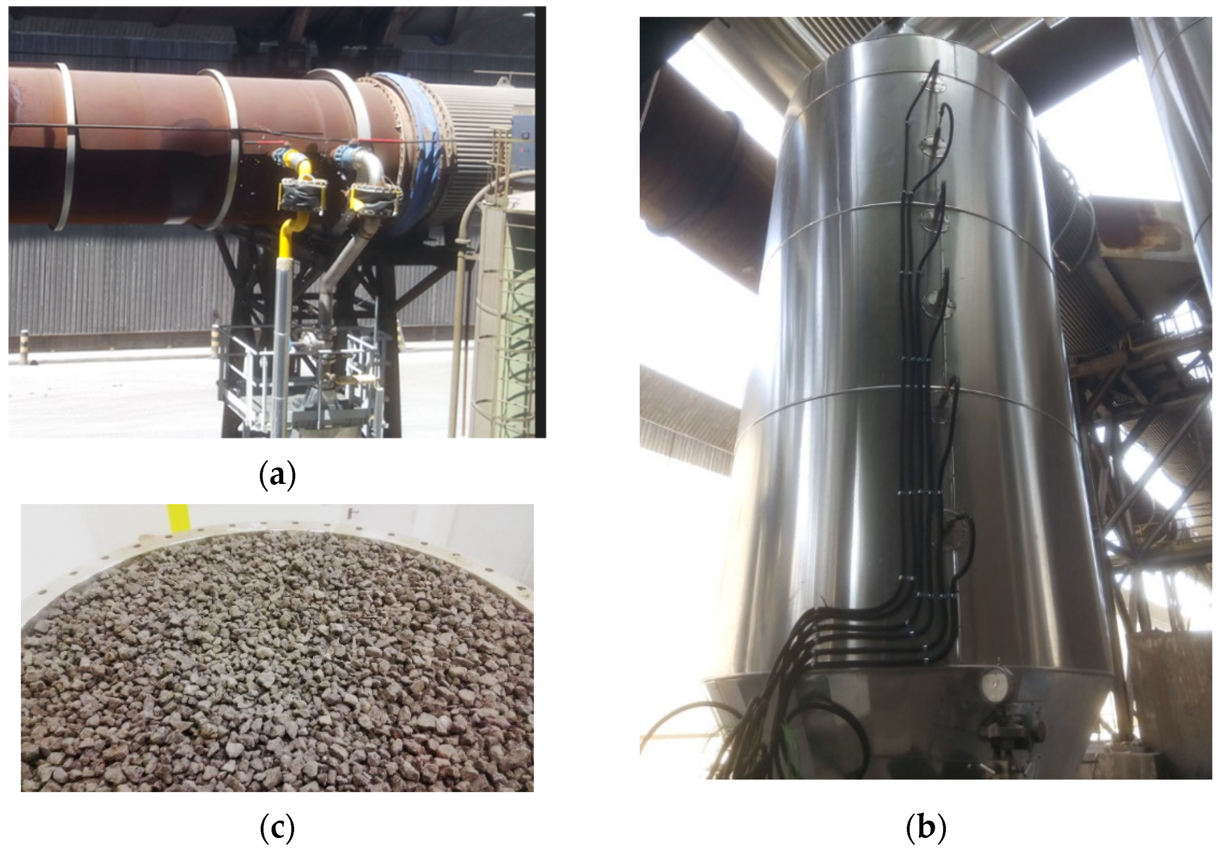
As mentioned in the introduction, the real-scale TES corresponds to a waste heat recovery plant installed in one of the steelworks of ArcelorMittal (Figure 2). The main parameters of the real-scale TES used to design the experiment are shown in Table 1.

2.2. TES Material Preparation

Before being introduced into the test tank, the steel slag particles (12–25 mm) obtained from ArcelorMittal, Sestao (Spain), which typically have angular and sharp edges, underwent a mechanical attrition process to enhance their roundness and smoothness. This attrition process involved placing the slag particles in a barrel tumbler that continuously rotated for 8 h, facilitating the reshaping of the slag particles. Additionally, this operation served to identify the most robust slag pieces, as the more porous or fragile ones tended to break into smaller fragments during the tumbling process. Subsequently, the slag particles were subjected to sieving, and particles smaller than 10 mm were excluded from the final product (Figure 3).

2.3. Description of the Testing Setup

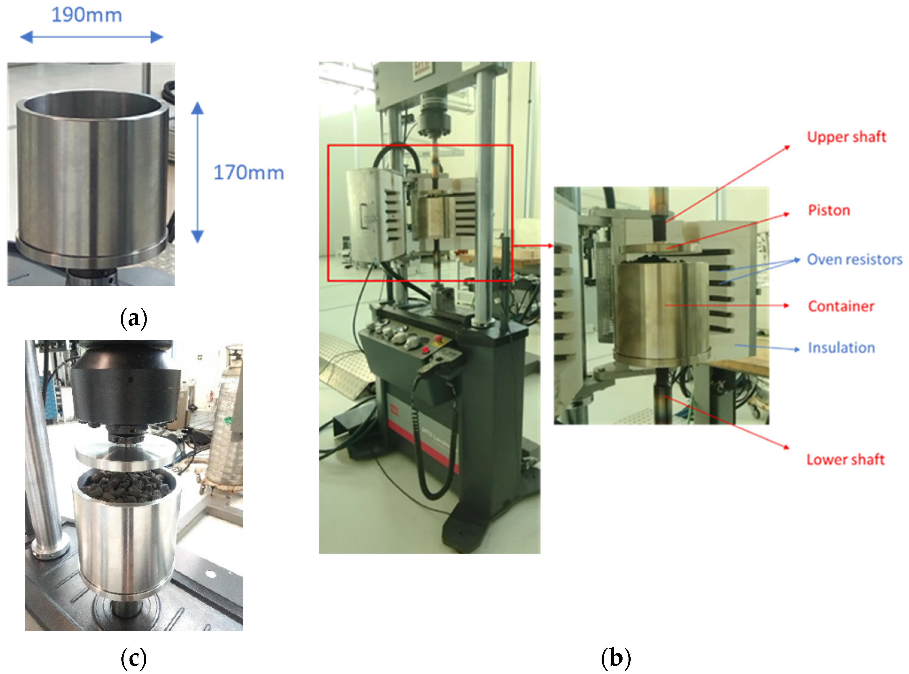
A custom-built small-scale cylindrical test tank (with an inner diameter of 190 mm and a height of 170 mm) was designed and positioned within the dynamic testing apparatus manufactured by MTS Systems Corporation, Minnesota (EEUU), which has a maximum load capacity of 100 kN and a working frequency ranging from 0.1 to 30 Hz. The material used for this test tank is identical to that of the TES tank located at ArcelorMittal steelworks in Sestao, which is constructed from steel 316L (Table 1). In the testing setup, this test tank moves in conjunction with a piston fixed to the upper shaft of the dynamic testing machine to apply pressure loads to the slag bed (Figure 4a–c).
For conducting high-temperature tests, a custom furnace is affixed to one of the machine’s pillars, ensuring that its position remains fixed relative to the movement of the lower shaft. This furnace features a hinged design, allowing it to accommodate the test tank, and it offers a temperature range spanning from room temperature to 1200 °C. Both components of the furnace are insulated and equipped with six electric heaters to facilitate the elevation of the assembly’s temperature.

2.4. Assessing the Mechanical Stability of the Filler Material

Throughout the tests, X-ray Computed Tomography (CT) was employed to assess both the thermomechanical stability of the slag particles and the morphology of the packed bed. The CT system used was the Compact 450 kV by YXLON, Hamburg (Germany) featuring a YTU 450-D09 tube and a linear detector with an effective length of 573 mm (as shown in Figure 5). This non-destructive technique proved highly effective in examining the distribution of slag particles and monitoring particle degradation, all without the need to disassemble the test rig.
However, it is worth noting that this equipment has certain limitations regarding the size of the component to be inspected. Specifically, it is suitable for items with a weight/load of less than 25 kg, a length under 350 mm, a height below 500 mm, and a wall thickness less than 65 mm for iron/steel. Therefore, the design of the TES tank was tailored to meet these requirements, ensuring that the resulting images are clear and of high quality.
Subsequent to the tests, the slag was removed from the test tank to assess the condition of each individual particle and to quantify the generated dust.

3. Results and Discussion

3.1. Steel Slag Characterization
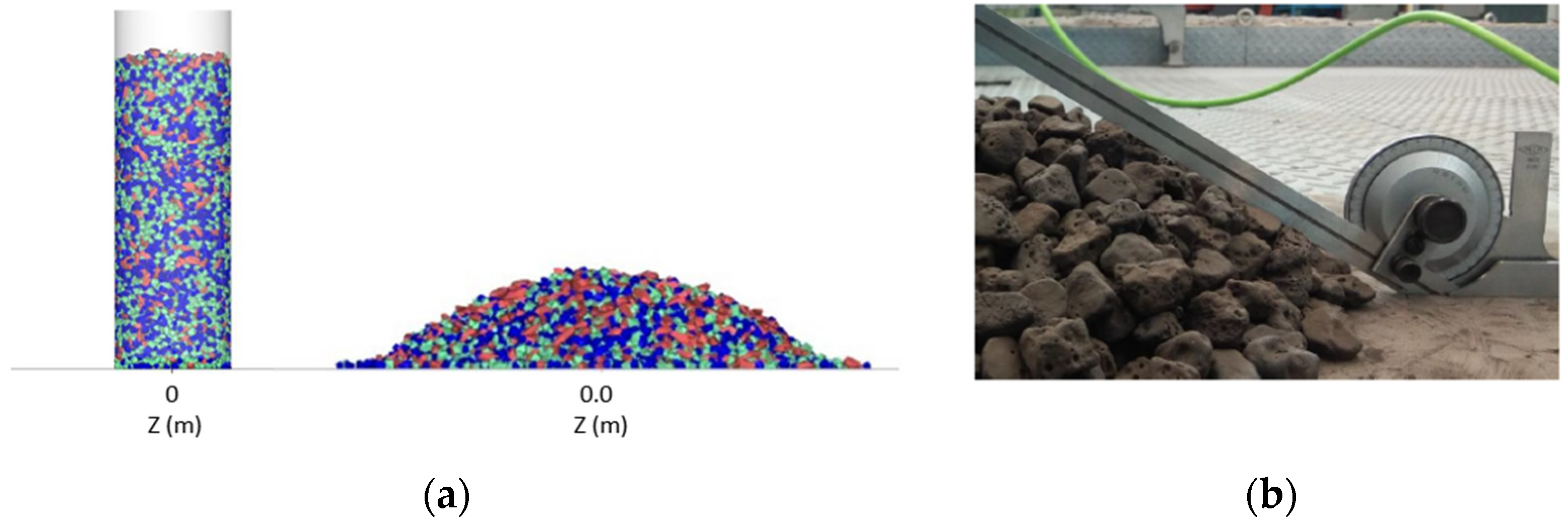
The angle of internal friction (φx) represents another important parameter for the calculation of the mechanical stresses. It depends mainly on the particle shape, size and surface roughness. The method applied in this work to determine it experimentally is explained below. It started filling a cylindrical container without a base or lid with a diameter of 200 mm with a specified mass of steel slag particles of the same size used in the TES prototype. Subsequently, the cylindrical container was lifted, allowing the material to spread out (Figure 5a). The inclination of the natural slopes corresponds to the angle of internal friction, returning a value of 30 ± 3° (Figure 5b). This value is in line with previous research for different rock types, reporting values between 21.4 and 39° [33].
Figure 5. Experimental determination of the angle of internal friction of the steel slag: (a) measuring methodology; (b) experimental measurement.
Energies 17 01515 g005

3.2. Determination of the Applied Forces

The compressive force representing the weight of the upper layers was calculated using the Janssen equation for silo stresses Equation (1). The value of the different parameters used are included in Table 2.
σ v = g · ρ b · A λ · tan φ x · U c · 1 e λ tan φ x · U c · z A
with σv: Vertical pressure, ρb: Effective density of the packed bed, which takes into account the slag density along with void fractions, A and Uc: Circular area and circumference of the packed bed, respectively, φx: Angle of internal friction previously determined, λ: Horizontal load ratio and z: Packed bed height.
As a result, a consistent load σv of 0.2 bar was determined. Considering that the piston area of the testing apparatus was 28,352 mm2, the equivalent load to represent the weight of the packed bed in the testing object corresponded to 0.65 kN.
Next, it is necessary to add the forces resulting from thermal expansions. However, determining the stresses resulting from thermal loads in a packed bed is not straightforward, as mentioned in the introduction. Krüger et al. provided maximum values for different packed bed TES systems as a function of temperature, with a similar size of steel slag as filler material, using a simplified DEM model [34]. Considering a temperature variation of 400 K, corresponding to our case study, the mean particle contact forces of the most similar system reached a value of around 1000 to 1500 N, which was taken as a reference for our analysis. It should be noted that even though the real value should be lower, since the static load is from 8 to 10 times greater in the reported study, the force increase due to reallocation of particles was not considered. Previous research has documented a rise in particle-wall and interparticle forces by a factor of 3 to 5 as a result of thermal cycling [25,28]. Therefore, this 1000 to 1500 N is considered as the equivalent force representing the thermal loads, assuming that it will be slightly overestimated.
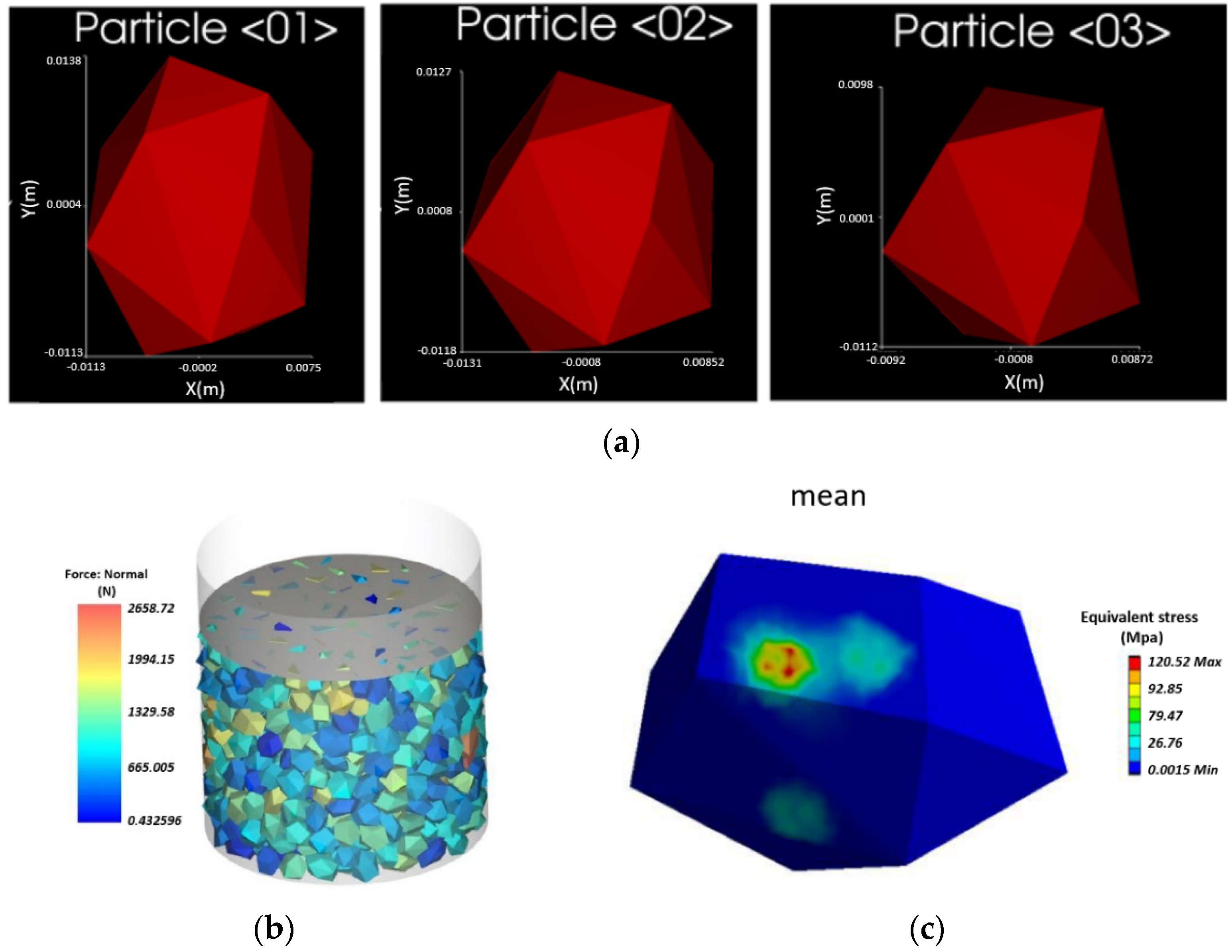
In order to determine the equivalent piston load that corresponds to the contact forces identified between particles, a DEM model of the testing object was built, and an inverse engineering approach was considered. For this study, we decided to include the particles in three polyhedral geometries, as shown in Figure 6a. In this way, the inherent inhomogeneity of the slag is represented more reliably, considering the variety of geometries and sizes that have been measured in the representative sample.
Several iterations were carried out until the mean contact forces resulting from the DEM simulations matched the required forces. The resulting average stress distribution between particles and over the particle surface are shown in Figure 6b and Figure 6c, respectively. As a result, a variable uniaxial compression load of 17.01 kN was determined. Input to the DEM model and results are shown in Table 3.
Consequently, a cyclic compression test was conducted, commencing at a load of 0.65 kN and incrementally increasing to 17 kN, with a frequency of 12 Hz, allowing a high number of cycles in a short time. This 12 Hz value was selected considering that previous works focused on studying the dynamic uniaxial compression behavior of different rocks reported an almost negligible compressive strength variation at this frequency range [34]. The most demanding scenario was considered, wherein the TES tank will undergo charging and discharging during each casting cycle. Therefore, considering that the thermal expansion of the steel slag is smaller than that of the container [35], it is exposed to two friction processes each casting, one during heating (charging) and another one during cooling (discharging). Consequently, according to a standard production rate, shown in Table 4, 15 years of operation would result in an equivalent 120,000 mechanical cycles.

3.3. Assesing the Performance of the Filler under Cycling Conditions

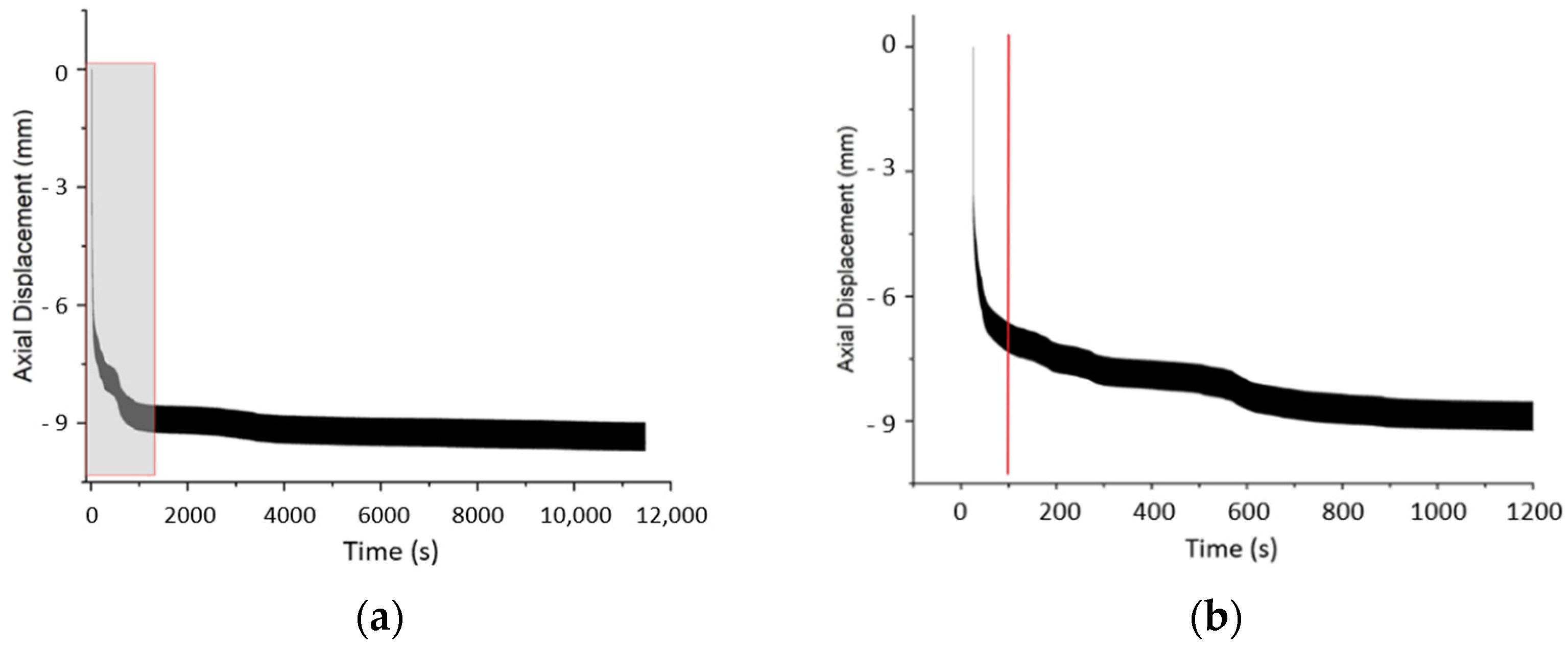
The applied force on the packed slag bed was continuously monitored throughout the cycles, spanning from −0.65 kN to −17.65 kN, as illustrated in Figure 7. Additionally, the displacement of the piston was tracked from the moment it made contact with the slag bed. Notably, after 120,000 cycles, equivalent to approximately 3 h of testing and 15 years of equivalent real operation (refer to Section 3.2), a piston displacement of approximately 9 mm was observed. Importantly, this displacement increased abruptly within the initial cycles of the test, after 100 s, corresponding to 1200 cycles and an equivalent one month of operation, as depicted in Figure 8a,b. After 4000 s of testing, corresponding to 44,000 cycles and 7 years of equivalent operation, the curve measuring the displacement decreased its slope until the end of the test, meaning that the particle reallocation kept occurring but at a much lower peace. This implies that the most significant particle redistribution and thus, potential damage due to increasing mechanical stress, should occur between the first month and seventh year of operation. After that, mechanical fatigue should be the main source of failure.
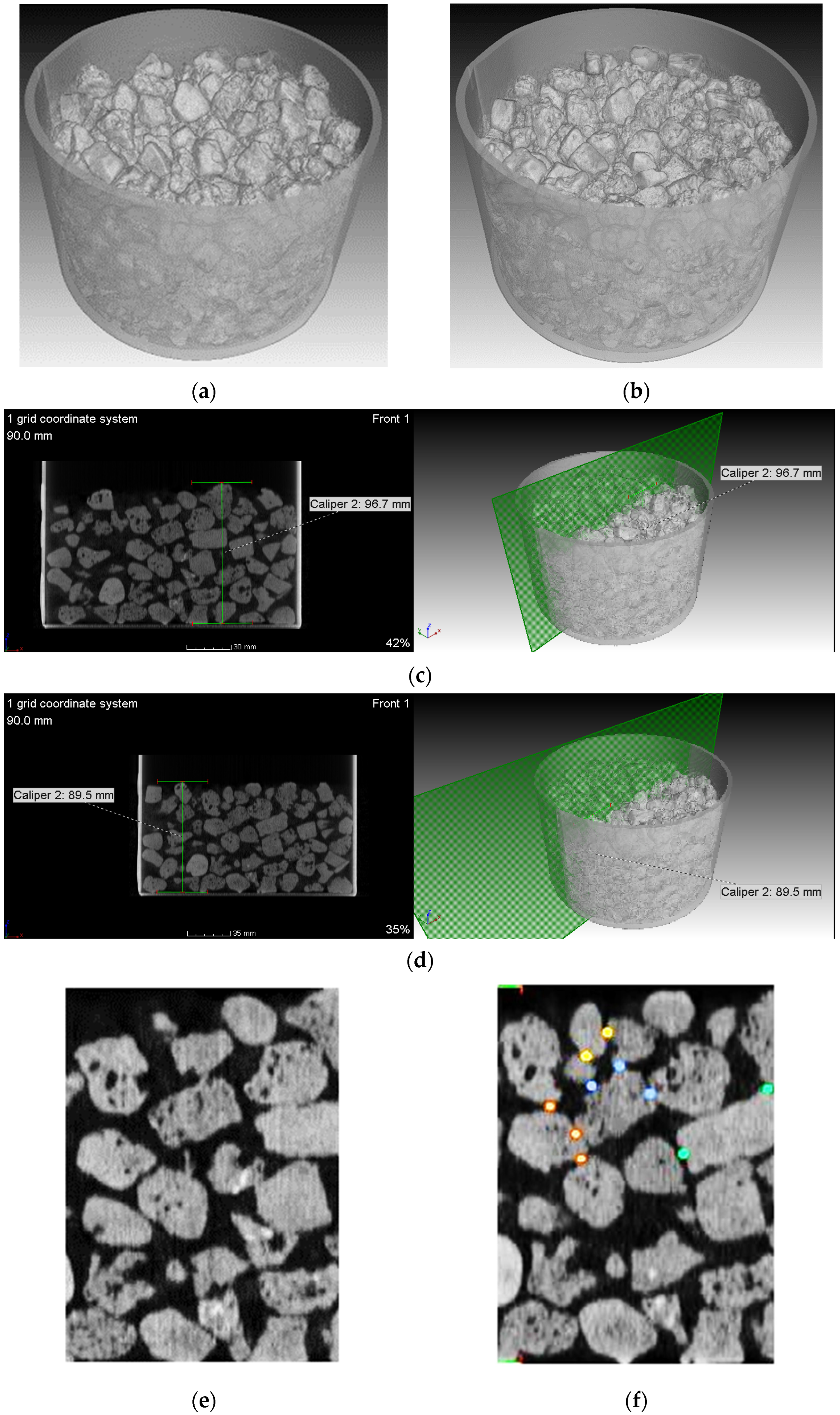
Following that, a second compression test was conducted using fresh slag particles. However, in this instance, the test was terminated after 1200 cycles, equivalent to a compression test duration of approximately 100 s or approximately two months of equivalent real operation. The test tank, containing the slag particles, underwent an X-ray Computed Tomography inspection, and the resulting data were compared to the tomography images taken before the test (as depicted in Figure 9a,b). Utilizing Volume Graphics software (VGStudio MAX 3.0) and the myVGL viewer, it became possible to make cross-sectional cuts in any region of the tank and perform a detailed comparison of both sets of images.
In a vertical cross-section taken at the same midpoint of the tank (as depicted in Figure 9c,d), one can observe the configuration of the slag-packed bed, its structural integrity, and the displacement of the slag following the test. Prior to the compression test, the slag-packed bed occupied a greater volume within the tank, extending to a height of 96.7 mm from the base to the top of the highest slag layer. However, after subjecting it to 1200 cycles at 400 °C, the load force induced a relocation of the slag particles, resulting in the packed bed being lowered by approximately 7 mm (now measuring 89.5 mm from the base to the top of the highest slag layer). Consequently, the combined effects of thermal and mechanical stresses, coupled with differences in expansion coefficients between the slag and the tank wall, led to the rearrangement of slag particles and potential particle cracking. It is worth noting that the stochastic nature of this arrangement had some influence on the results, since the vertical bed displacements differ slightly. Considering possible particle cracking during cycling, a magnification of the same tank section before and after the cycles is shown in Figure 9e,f, respectively, where the morphology of the different particles can be checked. From the images, one can infer a negligible particle degradation that will be confirmed later by visual inspection after the tests.
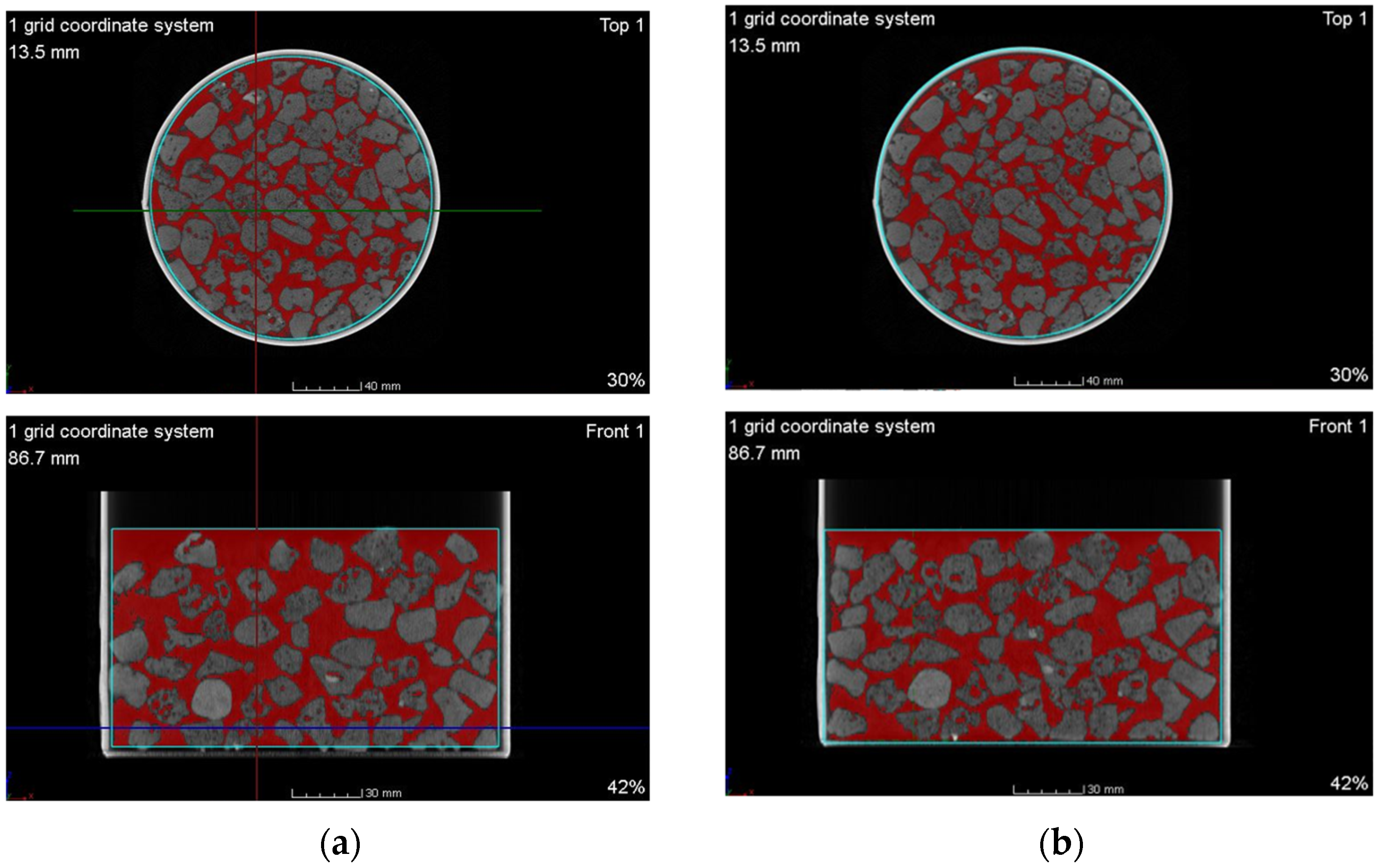
This tool also facilitates the precise calculation of the void fraction between the two sets of tomographic images. Figure 10a,b illustrate the decrease in void fraction (highlighted in red), reducing from 43.5 vol.% (equivalent to 1,079,474 mm3) to 39.9 vol.% (equivalent to 996,276 mm3) after the test. This reduction results in a compaction level of the packed bed of 7.71 vol.%, which approximates to the one derived from the measured bed height reduction (7.45 vol.%). As per the Ergun equation, widely employed in research studies [36], this reduction in voids may lead to an increase in pressure losses of up to 46%. Nevertheless, this resulting 39.9 vol.% of void fraction remains within the commonly accepted range for packed bed reactors, but it should be considered in the design of the pumping system.
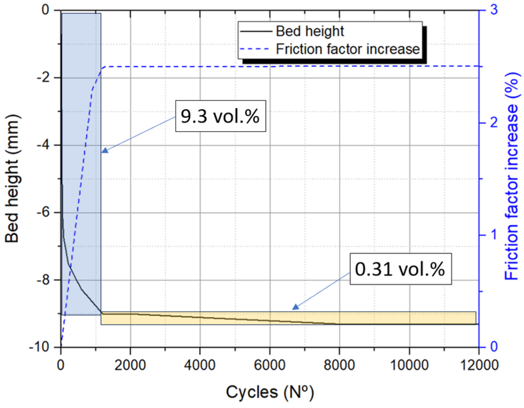
As stated at the beginning of the manuscript, in order to avoid TES system early failures and validate the equivalent intermittent force for the tests, it is important to evaluate the interparticle mechanical stress increase due to a higher bed compaction degree. Previous research has documented a rise in particle-wall and interparticle forces by a factor of 3 to 5 as a result of thermal cycling [25,28]. This increase appears to be linked to the correlation number, which represents the number of contact points between particles. Even though it is difficult to quantify from the 2D images (Figure 9e,f), an increase in the correlation number between 2- and 3-fold can be estimated after 1200 cycles. From there and considering that the compaction degree presents a much lower rate during the subsequent cycles (0.31 vol.%), we can assume that the correlation number will not vary significantly until the end of the cycles (Figure 11). It is expected that the friction factor between particles increases at the same rate as the correlation number, but establishing a direct correlation seems challenging and, therefore, the stability of the filler material has been checked experimentally.
To do so, the test tank was placed inside the furnace within the dynamic testing machine to complete the full set of 120,000 compression cycles. Following the completion of these cycles, the slag was removed from the test tank to assess the condition of each particle and measure the amount of dust generated.
A detailed examination was conducted on the slag particles, and they were categorized based on the extent of damage. These categories included slag with minor cuts on the edges, broken slag, and very small particles or slag dust. The respective percentages for these categories were determined to be 4.68 wt.%, 1.37 wt.%, and 0.22 wt.%, as depicted in Figure 12a–c.
Slightly damaged slag particles are capable of remaining within the packed bed, effectively storing heat without posing any issues in the TES system. On the other hand, more extensively broken slag particles, and particularly slag dust, present greater concerns. They have the potential to occupy the void fraction, leading to increased compaction of the packed bed, which in turn obstructs the proper airflow through the slag. This can result in a significant pressure drop within the system. Additionally, these particles may contribute to heightened mechanical stresses and could potentially damage the tank wall. However, it is worth noting that the sum of these critical broken slag particles (1.59 wt.%) remains relatively low even after undergoing 120,000 cycles, equivalent to 15 years of TES operation in a steel mill under demanding conditions. Extrapolating these results to the actual tank of 2.9 m height, with 6195 kg of slag, would imply a quantity of broken particles of 98.5 kg. In the event that these particles agglomerate at the bottom of the tank, it would occupy 13.83% of the empty fraction considering a height of 0.5 m, or 27.67% considering an even worse scenario where the broken slag allocate below 0.25 m of the tank height. Considering these results, air flow clogging is not expected, but an extra pumping power may be required. Including internal supports for the slag may help to reduce the mechanical stress due to the bed weight on the lower layers of slag and consequently, reduce the broken slag fraction.

4. Conclusions

Packed bed thermal energy storage systems are a cost-effective solution to deal with the intermittency of renewable energy sources or to increase the usability of industrial waste heat. Steel slag has been proposed as an attractive filler candidate for packed bed storage by many authors. Nevertheless, its structural integrity subjected to mechanical and thermal stresses over the expected long life of these systems must be ensured. Since subjecting the system to thermal cycles requires very long testing times, in this work a novel fast approach has been studied. The approach consisted in applying both a fixed and intermittent mechanical loads over a reduced scale heated sample, equivalent to those happening in a real-scale system for a waste heat recovery plant, during an equivalent 15 year of operation. The steel slag behavior was studied both via tomography and visual inspection. As a result, the findings revealed that the highest mechanical stresses happen between the first and seventh years of operation. After that, mechanical fatigue should be the main source of failure. Both tomography measurements and visual inspection confirm the structural integrity and long-term mechanical stability of steel slag as an inventory material in thermal energy storage systems for the specific temperature and configuration studied. A bed compaction degree of 7.71 vol.% was observed, which should not impose significant stresses over the particles, with a percentage of damaged particles around 1.59 wt.%. Nonetheless, as scheduled in the project plan, further investigations will be conducted to address the effects of thermal cycling, both in the tank wall and the filler material, employing a dedicated fast heating/cooling system under constant pressure conditions.

Author Contributions

Conceptualization, E.G. and D.B.; methodology, E.G.; validation, E.G. and I.M.; formal analysis, E.G. and I.M.; investigation, E.G., I.M. and P.A.; resources, E.G. and I.M.; data curation, E.G. and I.M.; writing—original draft preparation, E.G. and D.B.; writing—review and editing, P.A. and I.M.; project administration, E.G. and D.B.; funding acquisition, D.B. All authors have read and agreed to the published version of the manuscript.

Funding

This research was funded by the European Commission through LIFE programme, grant number LIFE20 CCM/ES/001733.

Data Availability Statement

The data presented in this study are available on request from the corresponding author.

Conflicts of Interest

The authors declare no conflicts of interest. The funders had no role in the design of the study; in the collection, analyses, or interpretation of data; in the writing of the manuscript; or in the decision to publish the results.

References

  1. IRENA. Global Energy Transformation: A roadmap to 2050, International Renewable Energy Agency, Abu Dhabi. 2018. Available online: https://www.irena.org/publications (accessed on 15 November 2023).
  2. Conti, J.P.; Holtberg, J.; Diefenderfer, A.; LaRose, J.T.; Turnure, L. Westfall, International Energy Outlook 2016 With Projections to 2040, Osti.Gov, United States. 2016. Available online: https://www.osti.gov/biblio (accessed on 15 November 2023). [CrossRef]
  3. Kuravi, S.; Trahan, J.; Goswami, D.Y.; Rahman, M.M.; Stefanakos, E.K. Thermal energy storage technologies and systems for concentrating solar power plants. Prog. Energy Combust. Sci. 2013, 39, 285–319. [Google Scholar] [CrossRef]
  4. Ortega-Fernández, I.; Uriz, I.; Ortuondo, A.; Hernández, A.B.; Faik, A.; Loroño, I.; Rodríguez-Aseguinolaza, J. Operation strategies guideline for packed bed thermal energy storage systems. Int. J. Energy Res. 2018, 43, 6211–6221. [Google Scholar] [CrossRef]
  5. Anderson, R.; Bates, L.; Johnson, E.; Morris, J.F. Packed bed thermal energy storage: A simplified experimentally validated model. J. Energy Storage 2015, 4, 14–23. [Google Scholar] [CrossRef]
  6. Bahrami, M.; Yovanovich, M.M.; Culham, J.R. Effective thermal conductivity of rough spherical packed beds. Int. J. Heat Mass Transf. 2006, 49, 3691–3701. [Google Scholar] [CrossRef]
  7. Pacheco, J.E.; Showalter, S.K.; Kolb, W.J. Development of a Molten-Salt Thermocline Thermal Storage System for Parabolic Trough Plants. J. Sol. Energy Eng. 2002, 124, 153–159. [Google Scholar] [CrossRef]
  8. Brosseau, D.; Kelton, J.W.; Ray, D.; Edgar, M.; Chisman, K.; Emms, B. Testing of Thermocline Filler Materials and Molten-Salt Heat Transfer Fluids for Thermal Energy Storage Systems in Parabolic Trough Power Plants. J. Sol. Energy Eng. 2005, 127, 109–116. [Google Scholar] [CrossRef]
  9. Gunerhan, H.; Hepbasli, A. Utilization of Basalt Stone as a Sensible Heat Storage Material. Energy Sources 2005, 27, 1357–1366. [Google Scholar] [CrossRef]
  10. Nahhas, T.; Py, X.; Sadiki, N. Experimental investigation of basalt rocks as storage material for high-temperature concentrated solar power plants. Renew. Sustain. Energy Rev. 2019, 110, 226–235. [Google Scholar] [CrossRef]
  11. Jemmal, Y.; Zari, N.; Maaroufi, M. Thermophysical and chemical analysis of gneiss rock as low cost candidate material for thermal energy storage in concentrated solar power plants. Sol. Energy Mater. Sol. Cells 2016, 157, 377–382. [Google Scholar] [CrossRef]
  12. Becattini, V.; Motmans, T.; Zappone, A.; Madonna, C.; Haselbacher, A.; Steinfeld, A. Experimental investigation of the thermal and mechanical stability of rocks for high-temperature thermal-energy storage. Appl. Energy 2017, 203, 373–389. [Google Scholar] [CrossRef]
  13. Tiskatine, R.; Eddemani, A.; Gourdo, L.; Abnay, B.; Ihlal, A.; Aharoune, A.; Bouirden, L. Experimental evaluation of thermo-mechanical performances of candidate rocks for use in high temperature thermal storage. Appl. Energy 2016, 171, 243–255. [Google Scholar] [CrossRef]
  14. Koçak, B.; Paksoy, H. Using demolition wastes from urban regeneration as sensible thermal energy storage material. Int. J. Energy Res. 2019, 43, 6454–6460. [Google Scholar] [CrossRef]
  15. Kocak, B.; Fernandez, A.; Paksoy, H. Benchmarking study of demolition wastes with different waste materials as sensible thermal energy storage. Sol. Energy Mater. Sol. Cells 2021, 219, 110777. [Google Scholar] [CrossRef]
  16. Py, X.; Calvet, N.; Olives, R.; Meffre, A.; Echegut, P.; Bessada, C.; Veron, E.; Ory, S. Recycled Material for Sensible Heat Based Thermal Energy Storage to be Used in Concentrated Solar Thermal Power Plants. J. Sol. Energy Eng. 2011, 133, 031008. [Google Scholar] [CrossRef]
  17. Keilany, M.; Milhé, M.; Bézian, J.-J.; Falcoz, Q.; Flamant, G. Experimental evaluation of vitrified waste as solid fillers used in thermocline thermal energy storage with parametric analysis. J. Energy Storage 2020, 29, 101285. [Google Scholar] [CrossRef]
  18. Gil, A.; Calvet, N.; Ortega, I.; Risueño, E.; Faik, A.; Blanco, P.; Rodríguez-Aseguinolaza, J. Characterization of a by-product from steel industry applied to thermal energy storage in Concentrated Solar Power. In Proceedings of the 99th Eurotherm Seminar—Advances in Thermal Energy Storage, Lleida, Spain, 28–30 May 2014. [Google Scholar]
  19. Gutierrez, A.; Miró, L.; Gil, A.; Rodríguez-Aseguinolaza, J.; Barreneche, C.; Calvet, N.; Py, X.; Fernández, A.I.; Grágeda, M.; Ushak, S.; et al. Advances in the valorization of waste and by-product materials as thermal energy storage (TES) materials. Renew. Sustain. Energy Rev. 2016, 59, 763–783. [Google Scholar] [CrossRef]
  20. Ortega-Fernández, I.; Calvet, N.; Gil, A.; Rodríguez-Aseguinolaza, J.; Faik, A.; D’Aguanno, B. Thermophysical characterization of a by-product from the steel industry to be used as a sustainable and low-cost thermal energy storage material. Energy 2015, 89, 601–609. [Google Scholar] [CrossRef]
  21. Polat, Ş.; Kahrıman, F. Microstructural and mechanical characterization of electric arc furnace (EAF) slag for use as abrasive grit material. Mater. Test. 2015, 57, 245–251. [Google Scholar] [CrossRef]
  22. Ortega-Fernández, I.; Wang, Y.; Durán, M.; Garitaonandia, E.; Unamunzaga, L.; Bielsa, D.; Palomo, E. Experimental validation of steel slag as thermal energy storage material in a 400 kWht prototype. In Proceedings of the Solarpaces 2018 International Conference on Concentrating Solar Power and Chemical Energy Systems (NewTech’23), Casablanca, Morocco, 2–5 October 2018. [Google Scholar]
  23. Bielsa, D.; Arribalzaga, P.; Ortega-Fernandez, I.; Garitaonandia, E. Experimental Testing Of a 400 KWh Steel Slag-Based Thermal Energy Storage Prototype for Industrial Waste Heat Recovery Applications. In Proceedings of the 9th World Congress on New Technologies (NewTech’23), London, UK, 9–11 August 2023. [Google Scholar] [CrossRef]
  24. Ortega-Fernández, I.; Rodríguez-Aseguinolaza, J. Thermal energy storage for waste heat recovery in the steelworks: The case study of the REslag project. Appl. Energy 2019, 237, 708–719. [Google Scholar] [CrossRef]
  25. Sassine, N.; Donzé, F.-V.; Harthong, B.; Bruch, A. Thermal stress numerical study in granular packed bed storage tank. Granul. Matter 2018, 20, 44. [Google Scholar] [CrossRef]
  26. Carson, J.; Craig, D. Silo design codes: Their limits and inconsistencies. In Proceedings of the 7th World Congress on Particle Technology (WCPT7), Beijing, China, 19–22 May 2014. [Google Scholar] [CrossRef]
  27. Mitterlehner, T.; Kartnig, G.; Haider, M. Analysis of the Thermal Ratcheting Phenomenon in Packed-Bed Thermal Energy Storage using Discrete Element Method. FME Trans. 2020, 48, 427–431. [Google Scholar] [CrossRef]
  28. Dreißigacker, V.; Zunft, S.; Müller-Steinhagen, H. A thermo-mechanical model of packed-bed storage and experimental validation. Appl. Energy 2013, 111, 1120–1125. [Google Scholar] [CrossRef]
  29. Sperl, M. Experiments on corn pressure in silo cells—Translation and comment of Janssen’s paper from 1895. Granul. Matter 2005, 8, 59–65. [Google Scholar] [CrossRef]
  30. Wang, W.; Zheng, X.; Ma, L.; Lin, W.; Yu, J. Ratcheting testing of polytetrafluoroethylene (PTFE) under multiple-step compression. Mater. Test. 2018, 60, 495–500. [Google Scholar] [CrossRef]
  31. Kuhlen, K.G.; Rothe, P.; Seifert, T. Near-component testing of materials for cylinder heads to determine thermomechanical fatigue under superimposed high-frequency mechanical loads. Mater. Test. 2021, 63, 1081–1089. [Google Scholar] [CrossRef]
  32. Mederos, F.S.; Ancheyta, J.; Chen, J. Review on criteria to ensure ideal behaviors in trickle-bed reactors. Appl. Catal. A Gen. 2009, 355, 1–19. [Google Scholar] [CrossRef]
  33. Zhang, N.; Li, C.C.; Lu, A.; Chen, X.; Liu, D.; Zhu, E. Experimental Studies on the Basic Friction Angle of Planar Rock Surfaces by Tilt Test. J. Test. Eval. 2019, 47, 256–283. [Google Scholar] [CrossRef]
  34. Zhang, Q.B.; Zhao, J. A Review of Dynamic Experimental Techniques and Mechanical Behaviour of Rock Materials. Rock Mech. Rock Eng. 2014, 47, 1411–1478. [Google Scholar] [CrossRef]
  35. Krüger, M.; Haunstetter, J.; Knödler, P.; Zunft, S. Slag as Inventory Material for a Thermal Energy Storage (TES): Material investigation and thermo-mechanical consideration. Energy Procedia 2018, 155, 454–463. [Google Scholar] [CrossRef]
  36. Trahan, J.; Graziani, A.; Goswami, D.Y.; Stefanakos, E.; Jotshi, C.; Goel, N. Evaluation of pressure drop and particle sphericity for an air-rock bed thermal energy storage system. Energy Procedia 2014, 57, 633–642. [Google Scholar] [CrossRef]
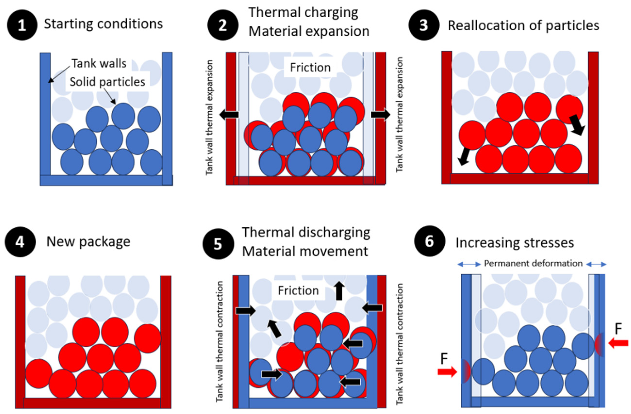
Figure 1. Description of the process resulting in additional mechanical stress due to the internal movement of the solid material inside a packed bed thermal energy storage system.
Energies 17 01515 g001
Figure 2. Pictures of the pilot plant at ArcelorMittal: (a) hot gas extraction point; (b) TES tank; (c) steel slag arrangement inside the TES.
Energies 17 01515 g002
Figure 3. Slag particles employed in the experimental trials and specific information regarding the external porosity of a subset of these particles.
Energies 17 01515 g003
Figure 4. Testing setup: (a) test tank dimension; (b) location of the test tank inside the furnace; (c) set up of the test in the LMK dynamic testing machine.
Energies 17 01515 g004
Figure 6. DEM model to determine the uniaxial compression force of the testing object representing the thermal loads of the real-scale prototype: (a) particle design; (b) force distribution over the particles; (c) resulting mean stress over a particle surface.
Energies 17 01515 g006
Figure 7. Cyclic load test between −0.65 kN and −17.65 kN, at the beginning, middle and end of the cycles.
Energies 17 01515 g007
Figure 8. Displacement of the slag during the test: (a) during 12,000 cycles highlighting in grey area the first 1200 s; (b) detail of the first 1200 s with a red line at 100 s corresponding to 1200 cycles.
Energies 17 01515 g008
Figure 9. X-ray computed tomography images: (a) sample before the compression test; (b) sample after 1200 cycles; (c) vertical cut in the middle of the test tank before the compression test; (d) vertical cut in the middle of the test tank after the compression test; (e) magnification of a tank section before the test; (f) magnification of a tank section after the test highlighting some of the newly formed interparticle contact points resulting from bed compaction, with a color corresponding to a different particle.
Energies 17 01515 g009
Figure 10. Void fraction (in red) of the slag packed bed: (a) before the test; (b) after the compression test.
Energies 17 01515 g010
Figure 11. Compaction degree evolution during 12,000 cycling tests and estimation of the friction force increase.
Energies 17 01515 g011
Figure 12. Damaged slag particles after the compression test: (a) Slag with a small cut in the edge; (b) Broken slag; (c) Slag dust.
Energies 17 01515 g012
Table 1. Main parameters of the real-scale TES.
Real-Scale TES Parameters
Tank materialAISI 316L
Tank diameter 1150 mm
Tank height2900 mm
Void fraction40%
Filler material amount (steel slag)6195 kg
Maximum charging temperature400 °C
Table 2. Values corresponding to the real-scale prototype used for the thermomechanical calculations.
ParameterValue
φx30 ± 3°
λ0.4
ρb2190 kg·m−3 [20]
A1.03 m2
Uc3611 mm
z2900 mm
Table 3. Values corresponding to the real-scale prototype used for the thermomechanical calculations.
DEM Inputs and Results
Slag Young modulus 22.56 GPa [30]
Slag Poisson ratio0.24 [30]
Slag density3650 kg·m−3 [20]
Static load0.65 kN
Variable load17.01 kN
Mean particle contact forces1320 N
Max. particle contact forces2658 N
Table 4. Common production rate in a steelworks with one EAF.
Production Rate
Casting size 100 t
Annual production 400,000 t/year
Annual castings 4000 castings/year
Disclaimer/Publisher’s Note: The statements, opinions and data contained in all publications are solely those of the individual author(s) and contributor(s) and not of MDPI and/or the editor(s). MDPI and/or the editor(s) disclaim responsibility for any injury to people or property resulting from any ideas, methods, instructions or products referred to in the content.