Article

Spinning of Carbon Nanofiber/Ni–Cu–S Composite Nanofibers for Supercapacitor Negative Electrodes

1
School of Materials and Energy, Lanzhou University, Lanzhou 730000, China
2
College of Electronic Engineering, Lanzhou City University, Lanzhou 730000, China
*
Authors to whom correspondence should be addressed.
Energies 2024, 17(6), 1449; https://doi.org/10.3390/en17061449
Submission received: 12 February 2024 / Revised: 10 March 2024 / Accepted: 13 March 2024 / Published: 18 March 2024
(This article belongs to the Section D2: Electrochem: Batteries, Fuel Cells, Capacitors)

Abstract

:
The preparation of composite carbon nanomaterials is one of the methods for improving the electrochemical performance of carbon-based electrode materials for supercapacitors. However, traditional preparation methods are complicated and time-consuming, and the binder also leads to an increase in impedance and a decrease in specific capacitance. Therefore, in this work, we reduced Ni-Cu nanoparticles on the surface of nitrogen-doped carbon nanofibers (CNFs) by employing an electrostatic spinning method combined with pre-oxidation and annealing treatments. At the same time, Ni-Cu nanoparticles were vulcanized to Ni–Cu–S nanoparticles without destroying the structure of the CNFs. The area-specific capacitance of the CNFs/Ni–Cu–S–300 electrode reaches 1208 mF cm−2 at a current density of 1 mA cm−2, and the electrode has a good cycling stability with a capacitance retention rate of 76.5% after 5000 cycles. As a self-supporting electrode, this electrode can avoid the problem of the poor adhesion of electrode materials and the low utilization of active materials due to the inactivity of the binder and conductive agent in conventional collector electrodes, so it has excellent potential for application.

1. Introduction

The consumption of fossil fuels has increased dramatically in recent decades, which has resulted in the rapid growth of environmental pollution and the energy crisis. People are looking for more useful, abundant, clean, and renewable energy resources to replace fossil energy [1,2]. Among the different renewable energy storage systems, electrochemical energy storage systems are the most attractive [3,4,5], because of their high efficiency, reasonable cost, and flexible capacity. Supercapacitors (SCs) have attracted a lot of attention from worldwide researchers in recent years because they are considered to be a potential alternative electrical energy storage technology that is closely related to rechargeable batteries and can further complement the energy storage abilities of a system. Meanwhile, supercapacitors are a new generation of electrochemical energy storage devices. In the past decade, supercapacitor technology has realized its great application potential in commercial-scale energy storage systems. Compared with conventional rechargeable batteries, SCs have short charge and discharge times and long cycle life, and they are lightweight and environmentally friendly [6,7]. The chemical properties of SCs mainly depend on their electrode materials [8], and SCs can be divided into two categories: electrostatic double-layer capacitors (EDLCs) and pseudocapacitive capacitors (PCs) [9,10]. The former can achieve capacity storage by accumulating different electrostatic charges at the electrode and electrolyte interfaces, while the latter option relies on rapid reversible redox processes occurring on or near the surface of the electrode material. However, carbon-based EDLCs can only achieve very low energy densities of 3–5 Wh kg−1 [11]. Heteroatom doping (such as N, P, and S) is one of the effective ways of improving the performance of carbon-based EDLCs. Doping N into carbon nanofibers (CNFs) can effectively improve electrical conductivity and modulate the electronic structure of the carbon matrix, which is beneficial for improving the ion exchange at active sites. Wang et al. [12] prepared nitrogen-doped mesoporous carbon nanotubes via the hard template method. The resulting nitrogen-doped mesoporous carbon nanotubes had a large specific surface area (1037 m2 g−1) and were uniformly nitrogen-doped, with a device energy density of 11.6~8.8 Wh kg−1 and a power density of 6261 W kg−1 instead of 313 W kg−1, which is superior to most of the porous carbon-based symmetric supercapacitors.
Meanwhile, transition metal compounds can be used as electrode materials for SCs [13,14,15], and they have a high specific surface area as well, which always contributes to the good electrochemical performance of supercapacitors. For example, ternary nickel–copper–sulfide has rich redox reactions and active sites. Yu Cheng et al. [16] prepared uniform and dense Ni-Cu films on the nickel foam surface using typical filter cathode vacuum arc technology, and the electrode was electrochemically vulcanized, which provided a specific capacity of 1975.2 C g−1 at 0.5 mA cm−2; the capacitance retention rate was 76.8% after 3000 cycles at 10 mA cm−2. Dai et al. [17] successfully designed Sn-Ni-Co-S nano-arrays with a three-dimensional spherical structure on nickel foam using a thermal solvent, and the unique spherical structure provided a larger specific surface area. In addition, the efficient synergy among Sn, Ni, and Co elements greatly improved the redox reaction capability of the electrode materials. As a result, the Sn-Ni-Co-S composite exhibited excellent performance in the three-electrode system with a specific capacitance as high as 18.6 F cm−2 at a current density of 5 mA cm−2.
Nevertheless, the synthesis of transition metal compounds is usually carried out via the hydrothermal method, which has the disadvantages of complexity, is time-consuming, and is unable to be directly compounded with porous carbon materials. Thus, there is an urgent need to devise a simple and economical way of strongly coupling transition metal compounds with CNFs. Electrostatic spinning is a simple and effective technique for preparing polymer nanofibers under high pressure [18]. The uniqueness of electrospinning technology lies in its applicability in fabricating materials from various organic polymers while incorporating inorganic metal oxides, CNFs, graphene, and other nanomaterials or nanomaterial precursors [19,20,21,22,23]. W. Luoa and H. Xue [24] successfully prepared hybrid nickel–cobalt–oxygen-embedded CNF (nickel–cobalt–oxygen–CNF) nanocomposites using a one-step electrostatic spinning method and heat treatment. The hybridized (nickel–cobalt–oxygen–CNFs) nanocomposites exhibited good supercapacitance performance with a specific capacitance of 836 F g−1 and retention of 80.9% after 2000 cycles. In addition, electrospinning technology is more attractive and promising for practical applications due to its ease of operation, environmental friendliness, and large-scale production capacity [18,25,26,27,28,29].
In this paper, a method for the preparation of electrode materials based on nitrogen-doped CNFs and transition metal compounds using electrospinning technology is proposed; i.e., the electrodes are pre-oxidized at low temperatures to reduce Ni-Cu nanoparticles on the surface of carbon nanofibers. Sublimated sulfur was used as the sulfur source to transform the Ni-Cu nanoparticles into Ni–Cu–S nanoparticles without destroying the nanofiber’s structure. It is also worth noting that the Ni–Cu–S/CNF electrodes are self-supported films without the use of binders or conductive agents such as polyvinylidene fluoride (PVDF) and polyvinyl alcohol (PVA), which usually reduce the extra volume/mass and produce almost no charge co-absorption. In the presence of Ni–Cu–S, the electrodes exhibited good stability and electrochemical activity, while the CNF electrodes showed a significant increase in specific surface area as well as good cycling stability.

2. Experimental Section

2.1. Chemicals and Materials

Polyacrylonitrile (PAN, Mw 149,000~151,000; Shanghai Aladdin Biochemical Technology Co., Ltd., Shanghai, China), polyvinyl pyrrolidone (PVP, Mw 1,300,000; Shanghai Aladdin Biochemical Technology Co., Ltd., China), nickel nitrate hexahydrate (Ni(NO3)2·6H2O, Mw 290.785, analytically pure; Chengdu Cologne Co., Chengdu, China), copper nitrate trihydrate (Cu(NO3)2·3H2O, Mw 241.6, analytically pure; Chengdu Cologne Co., China), sulfur powder (S, -325 items; Alfa Aesar Chemical Co., Shanghai, China), and N,N-dimethylformamide (DMF; Tianjin Lianlong Bohua Pharmaceutical Chemical Co., Tianjin, China) all formed part of the experimental process.

2.2. Material Characterization Instruments and Equipment

The microscopic morphology of the prepared materials was observed using a field emission scanning electron microscopy (FE-SEM, Hitachi S-4800; Hitachi, Tokyo, Japan) and a transmission electron microscopy (TEM, Tecnai G2 F30, 300 kV; FEI, US). The physical structures of the materials were characterized using an X-ray diffractometer (XRD, Rigaku D/MAX-2400, Co Kα, λ = 0.1541056 nm). The elements and chemical states in the samples were tested and analyzed using a multifunctional X-ray photoelectron spectrometer (XPS, PHI-5702, Mg KR excitation source with an excitation energy of 1253.6 eV; Physical Electronics Co., Dallas, TX, USA). The specific surface area and pore structure of the materials were tested and analyzed with a BET physical adsorption tester (Mike ASAP-2460, with a degassing temperature of 300 °C degassing time of 12 h, adsorption gas of N2; Micromeritics, Shanghai, China).

2.3. Preparation of the CNFs/Ni-Cu and CNFs/Ni–Cu–S Electrodes

CNFs/Ni-Cu electrodes were prepared with electrospinning technology (Figure 1). Initially, 1.5 g of PAN and 0.5 g of PVP were weighed and dissolved into 15 mL of DMF, and stirred at 1100 r min−1 on a constant temperature magnetic stirrer at 60 °C for 2 h until light yellow solutions were formed Then, 150 mg of Ni(NO3)2·6H2O and 150 mg of Cu(NO3)·3H2O, 300 mg of Ni(NO3)2·6H2O and 300 mg of Cu(NO3)2·3H2O, and 450 mg of Ni(NO3)2·6H2O and 450 mg of Cu(NO3)2·3H2O were taken and added to 5 mL of DMF and stirred on a magnetic stirrer until completely dissolved to obtain different concentrations of green solutions. The two prepared solutions were mixed and stirred thoroughly to obtain spinning solutions, which were named as Ni–Cu–150, Ni–Cu–300, and Ni–Cu–450.
The prepared two solutions were mixed and stirred thoroughly to obtain the spinning solution. Then, electrospinning was performed at a flow rate of 0.6 mL h−1 at a voltage of 14 kV to obtain nanofibers. Subsequently, the achieved homogeneous polymer nanofibers were stabilized at 230 °C for 2 h in air atmosphere, and then calcined at 800 °C for 2 h in an argon atmosphere, during which the polymer nanofibers were carbonized into N-doped CNFs and Ni-Cu were produced via reduction corresponding to different concentrations of CNFs/Ni–Cu–150, CNFs/Ni–Cu–300, and CNFs/Ni–Cu–450. The reduced Ni-Cu was then sulfurized in a sulfur atmosphere at 550 °C for 2 h to obtain CNFs/Ni–Cu–S nanoparticles (Table 1), and the carbon nanofiber structure remained intact, benefitting from the synergistic effect of the one-dimensional structural features of Ni–Cu–S and N-doped carbon nanofibers.

2.4. Electrochemical Measurements

Electrochemical performances were carried out on a CHI 760E electrochemical workstation (Shanghai Chenhua Instruments Co., Ltd., Shanghai, China) with a three-electrode system. The synthesized electrodes (CNFs/Ni-Cu and CNFs/Ni–Cu–S) were used as working electrodes. The Pt sheet and Hg/HgO were used as counter and reference electrodes, respectively. The electrochemical activities of the electrodes prepared for both CNFs/Ni-Cu and CNFs/Ni–Cu–S electrodes with an area of 1 cm2 were evaluated by cyclic voltammetry (CV), constant current charge and discharge (GCD), and electrochemical impedance spectroscopy (EIS). Both electrodes were tested in a 1 M KOH electrolyte, and the CV measurements were performed at different scan rates in the potential range of −0.8 V–0 V with a scan range of 1–25 mV s−1. GCD tests were performed in the potential range of −0.8 V–0 V with a current density range of 1–10 mA cm−2. The area capacitance (C, mF cm−2) was calculated using the following equation:
C = I t S V
where I (A) is the constant discharge current; ∆t (s) is the discharge time; S (cm2) is the area of active substance; and ∆V (V) is the voltage window in which the electrode operates.

3. Results and Discussion

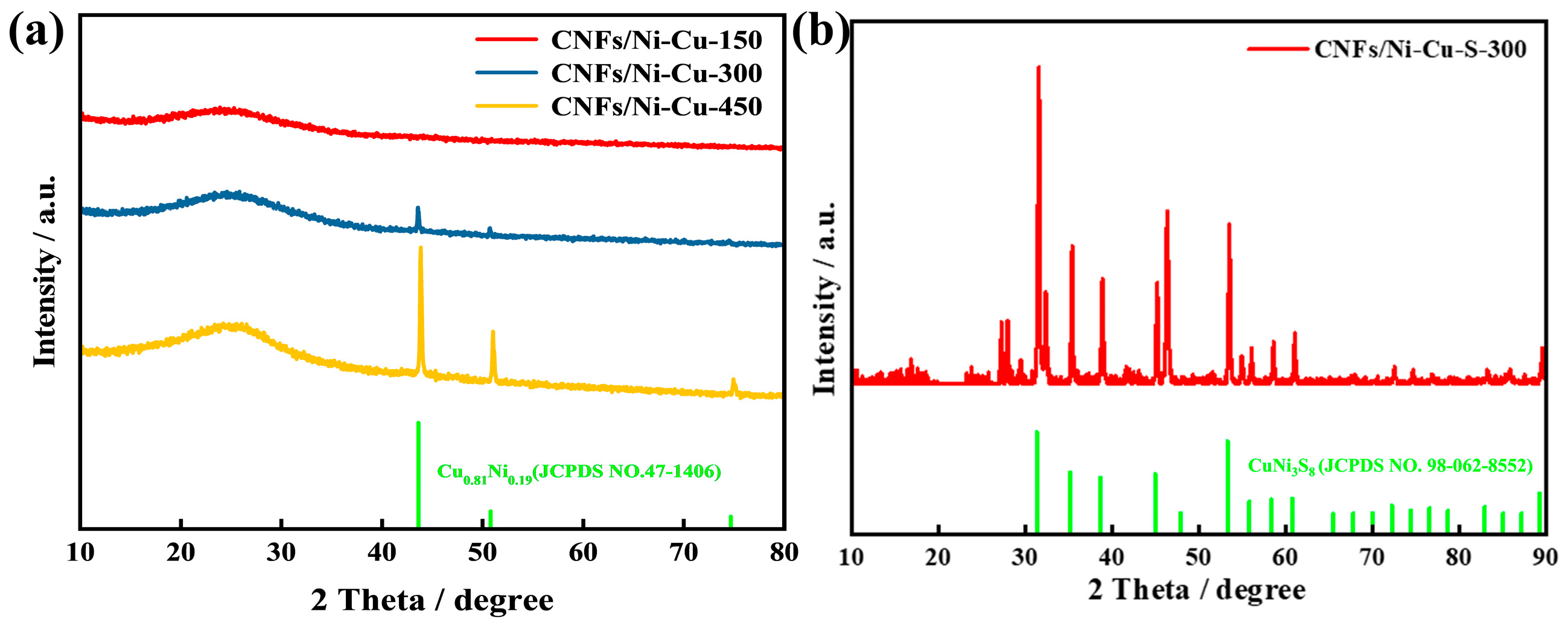
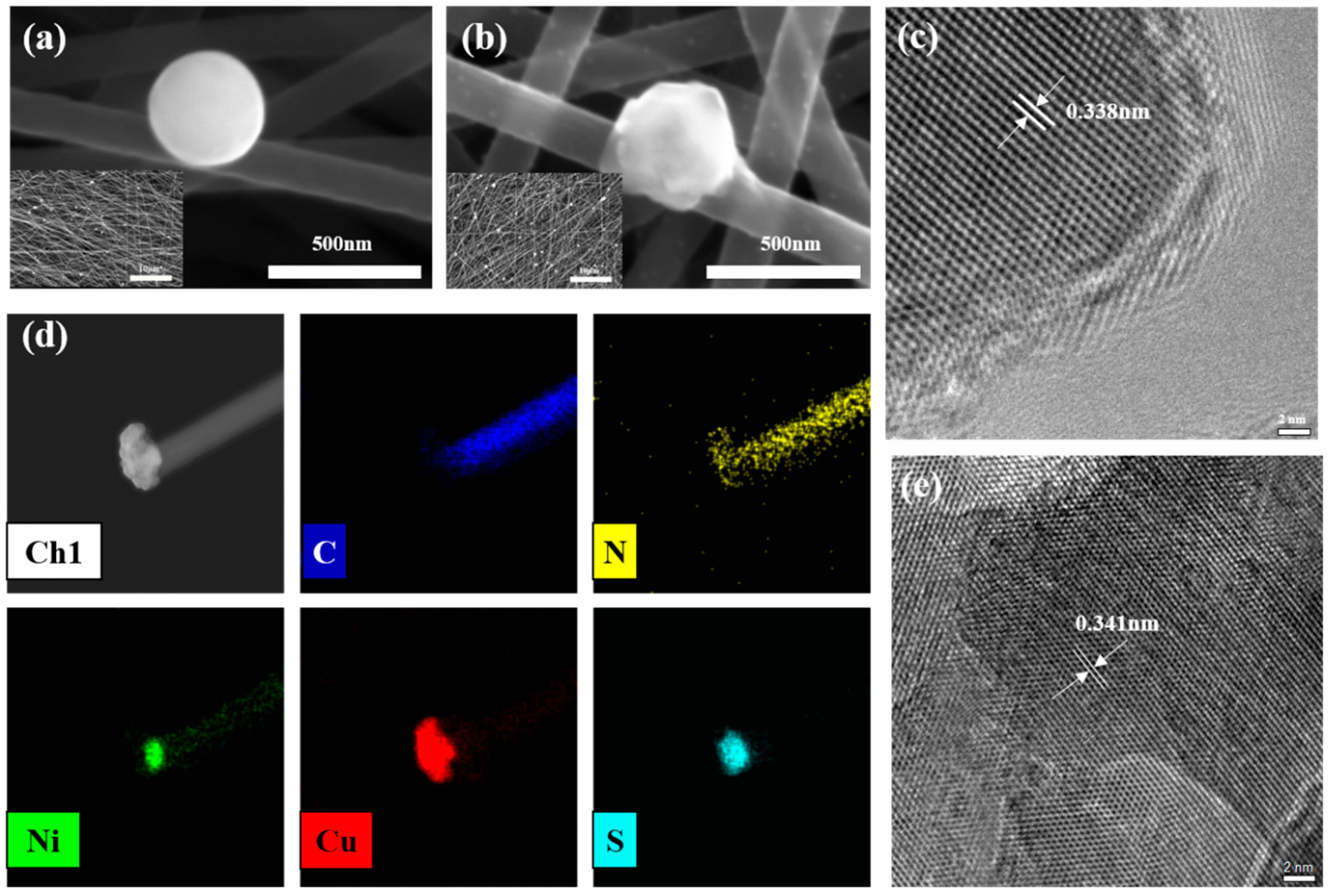
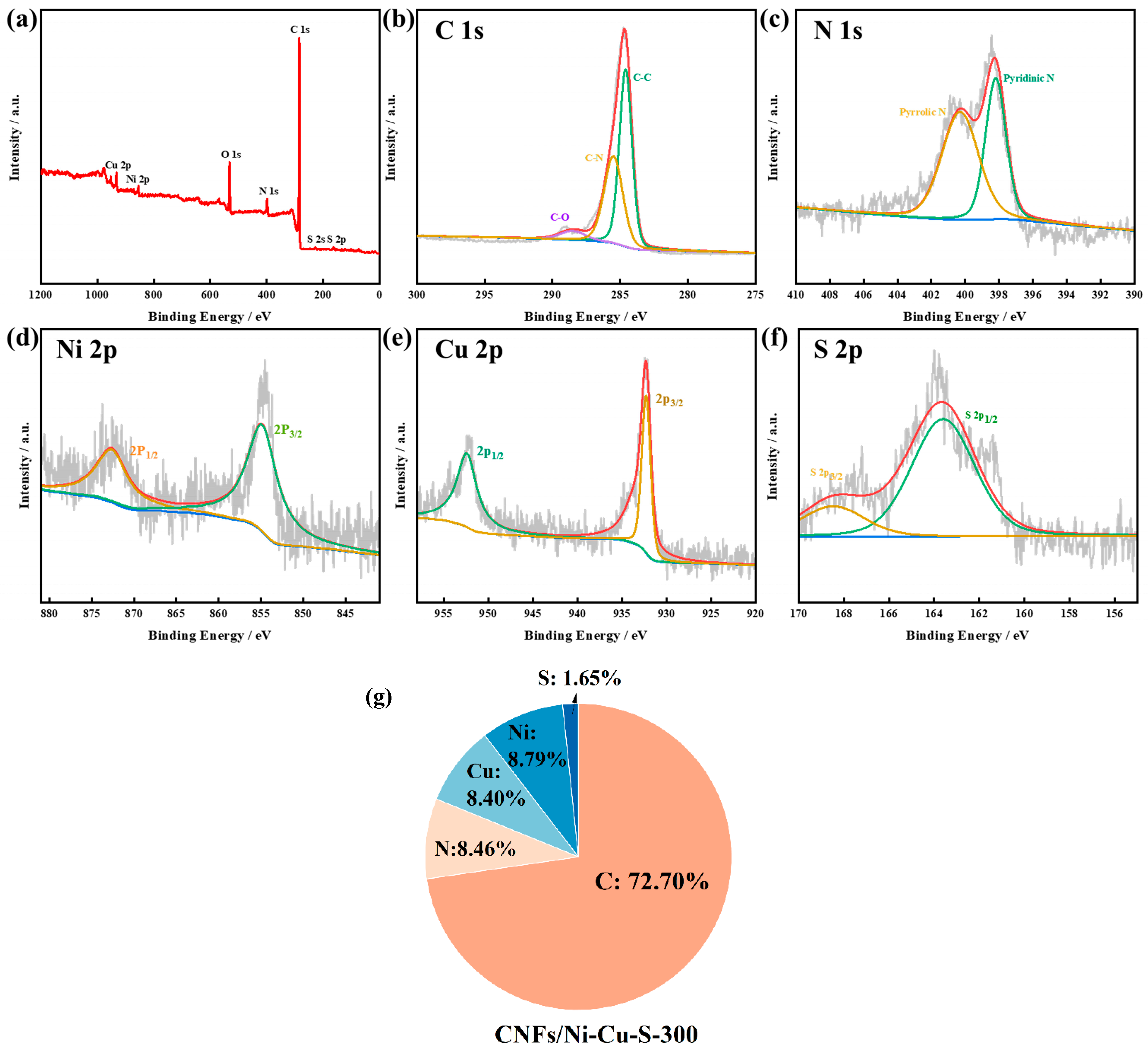
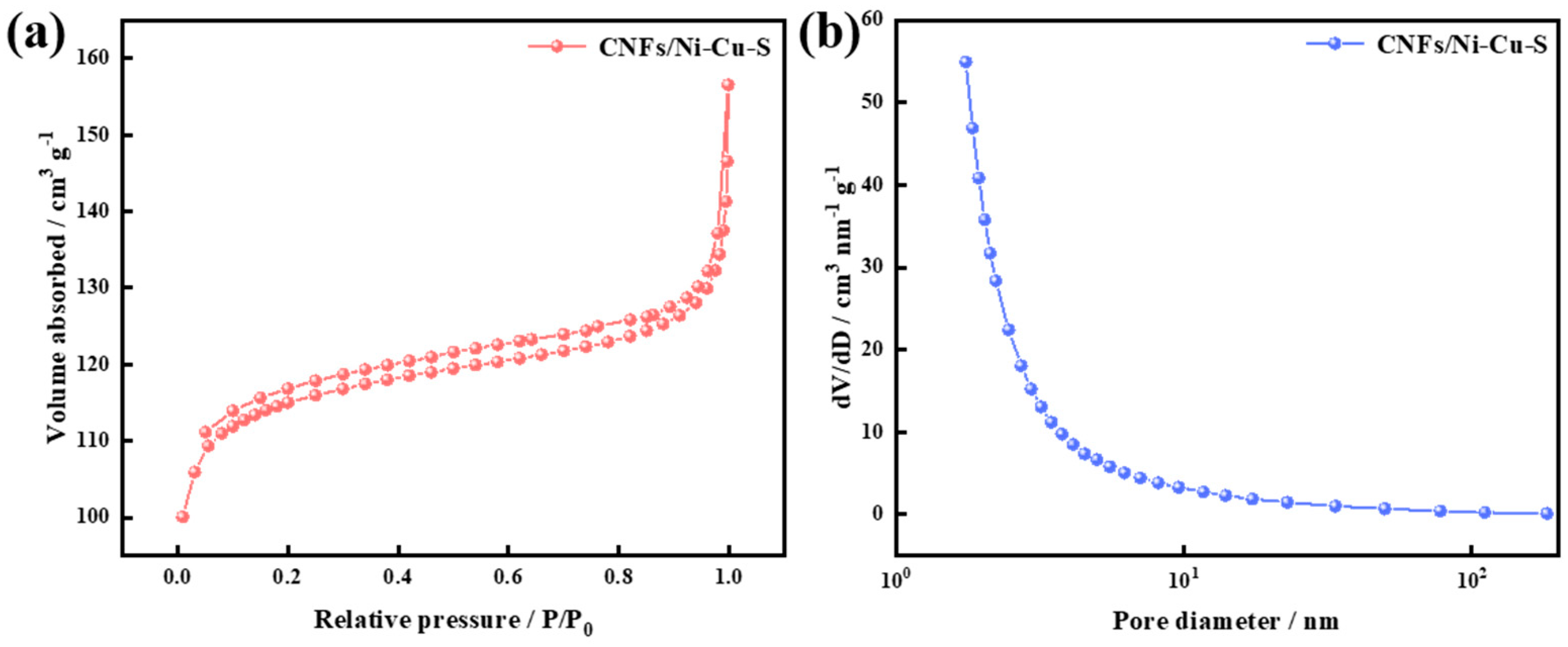
3.1. Material Characterization

The structures of the CNFs/Ni-Cu were analyzed by XRD, and as shown by Figure 2a, 43.8°, 50.9°, and 74.7° of the (111), (200), and (220) planes of Cu0.81Ni0.19 (JCPDS NO.47-1406) are observed, respectively, which are consistent with the data measured by high-resolution transmission electron microscopy (HRTEM). The XRD pattern also has a distinct carbon peak. With an increase in the spinning solution concentration, the diffraction peak of Cu0.81Ni0.19 becomes more and more obvious. As can be seen from Figure 2b, the characteristic XRD peaks of the CNFs/Ni–Cu–S–300 sample are evident at 31.4°, 35.2°, 38.7°, 45.0°, and 55.9° corresponding to the (002), (021), (112), (022), and (222) crystal planes of CuNi3S8 (JCPDS NO. 98-062-8552), respectively. The (111) crystal plane located at 27.1° is consistent with the crystal plane spacing measured with the TEM [16,30]. Figure 2b shows the appearance of additional, non-characteristic peaks, which is due to the introduction of the elemental S through S vapor vulcanization during our preparation, the attachment of S monomers to the material, and the impurities and contaminants introduced by the preparation process.
The carbonized samples maintained the nanofiber structures obtained by the spinning. The prepared nanoparticles were spherical with an average diameter of between 150 and 400 nm. According to the low-magnification plot S1, S2, it can be analyzed that the nanoparticle distribution concentration increased with the addition of salt. The samples exhibited no obvious agglomeration behavior and the distribution was relatively uniform despite gradient concentrations. As shown in Figure 3a,b, the structure of the Ni–Cu–S nanoparticles remains intact and the particle size did not change much after sulfidation. But many folds appeared on the surface, which were caused by the sulfidation reaction of Cu0.81Ni0.19 obtained by carbonization reduction with sublimated sulfur vapor at 550 °C to achieve CuNi3S8. After sulfidation, these nanoparticles were tightly bound to CNFs and had a significantly higher specific surface area. The open three-dimensional structure is more beneficial to the efficient transport of electrons and ions between the electrode and electrolyte; thus, the electrochemical performance of the electrodes has been effectively improved. Figure 3c–e are the HRTEM images of CNFs/Ni–Cu–300 and CNFs/Ni–Cu–S–300, where visible stripes can be observed. A lattice spacing of 0.338 nm was observed from Figure 3c, corresponding to the (220) crystal plane of the CNFs/Ni–Cu–300 sample. On the other hand, the lattice fringe spacing of 0.341 nm, corresponding to the (111) crystal plane of CuNi3S8, is consistent with the XRD results. Figure 3d shows the mapping plot of C, N, Ni, Cu, and S elements in the sample, from which it can be seen that C and N are uniformly distributed on the carbon nanofibers, while Ni, Cu, and S are distributed on the nanoparticles. It can be found that during the sulfidation process, the sublimated sulfur did not enter the pores of the carbon nanofibers, but only reacted with the nanoparticles. The cross-sections of CNFs/Ni–Cu–S samples were characterized by SEM, and it can be seen from the S3 that the thicknesses of CNFs/Ni–Cu–S–150, CNFs/Ni–Cu–S–300, and CNFs/Ni–Cu–S–450 electrodes were 121.4 μm, 131.8 μm, and 134.9 μm, respectively, with a maximum difference of 13.5 μm. In subsequent electrochemical tests, the area capacitance method was used to calculate the area specific capacity of the electrodes, and for the self-supporting electrodes, the thickness proximity allows a more accurate comparison of the area specific capacity of these electrodes.
The CNFs/Ni–Cu–S–300 sample was subjected to XPS testing to characterize its elemental composition and chemical states. The characteristic peaks appearing in the full XPS spectrum of CNFs/Ni–Cu–300 correspond to the elements of C, N, O, and Ni, respectively (S6). Figure 4a is the full XPS spectrum of the CNFs/Ni–Cu–S–300 sample, where the elements C, N, Ni, Cu, and S correspond to their characteristic peaks, respectively. The appearance of O originates from the adsorption of O in the air. Three distinct, fitted peaks at 284.8 eV, 285.4 eV, and 288.1 eV can be seen in Figure 4b, representing carbon-carbon single bond (C-C), carbon-nitrogen bond (C-N), and carbon-oxygen single bond (C-O) [31], respectively. In Figure 4c, two different fitted peaks of the N 1s spectra at 400.3 eV and 398.7 eV for pyrrole nitrogen and pyridine nitrogen are presented, respectively [32]. The Ni 2p, Cu 2p, and S 2p fine spectra were decomposed into two self-selected orbitals using a Gaussian fit, as shown in Figure 4d–f. The S 2p1/2 energy level is related to the binding energy of Ni-S and Cu-S bond, while the S 2p3/2 energy level can prove the presence of sulfur ions in a low coordination state on the surface [33,34]. The XPS results show that the Ni–Cu–S–300 is composed of Ni2+, Cu2+, and S2− [35]. Based on the XPS test results, the integral calculated the elemental composition ratio of C, N, Cu, Ni, and S in CNFs/Ni–Cu–S–300, as shown in Figure 4g, in which C is the main component with 72.70%. The contents of N, Cu, and Ni elements are 8.46%, 8.40%, and 8.79%, respectively, and similar results are observed for the elemental composition ratio of CNFs/Ni–Cu–300 (Figure S6e); notably, the samples were sulfurized to introduce 1.65% of S. Figure 5a shows the adsorption–desorption curve of the CNFs/Ni–Cu–S–300 sample in N2, which implies the porous structure of the material is a typical type IV microporous structure [36]. The specific surface area was 371.063 m2 g−1 and the pore volume was 0.149 cm3 g−1, respectively. By comparing the specific surface area and pore structure between the CNFs/Ni–Cu–S–300 and CNFs/Ni–Cu–300 in Table 2, it can be seen that there are more ion adsorption sites in the CNFs/Ni–Cu–S–300.

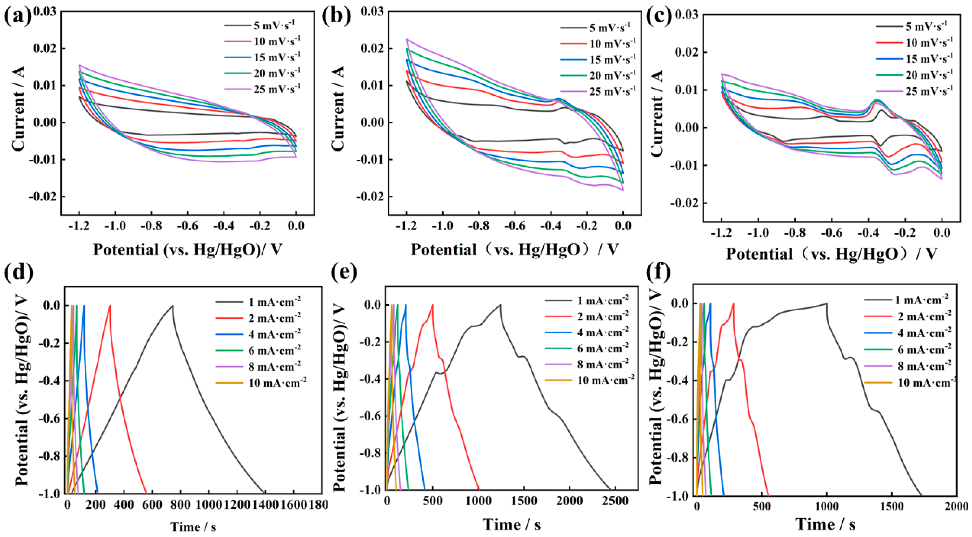
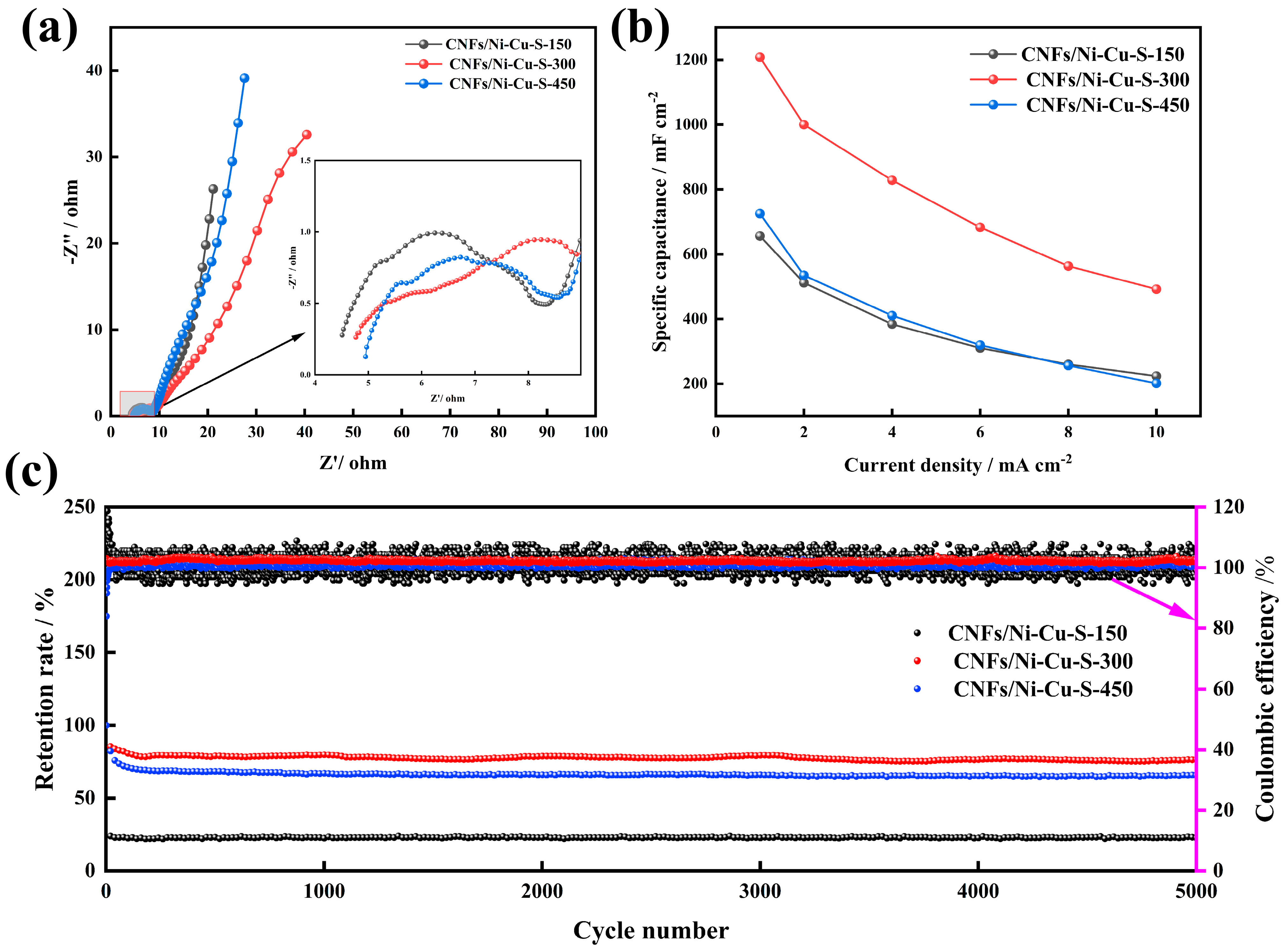
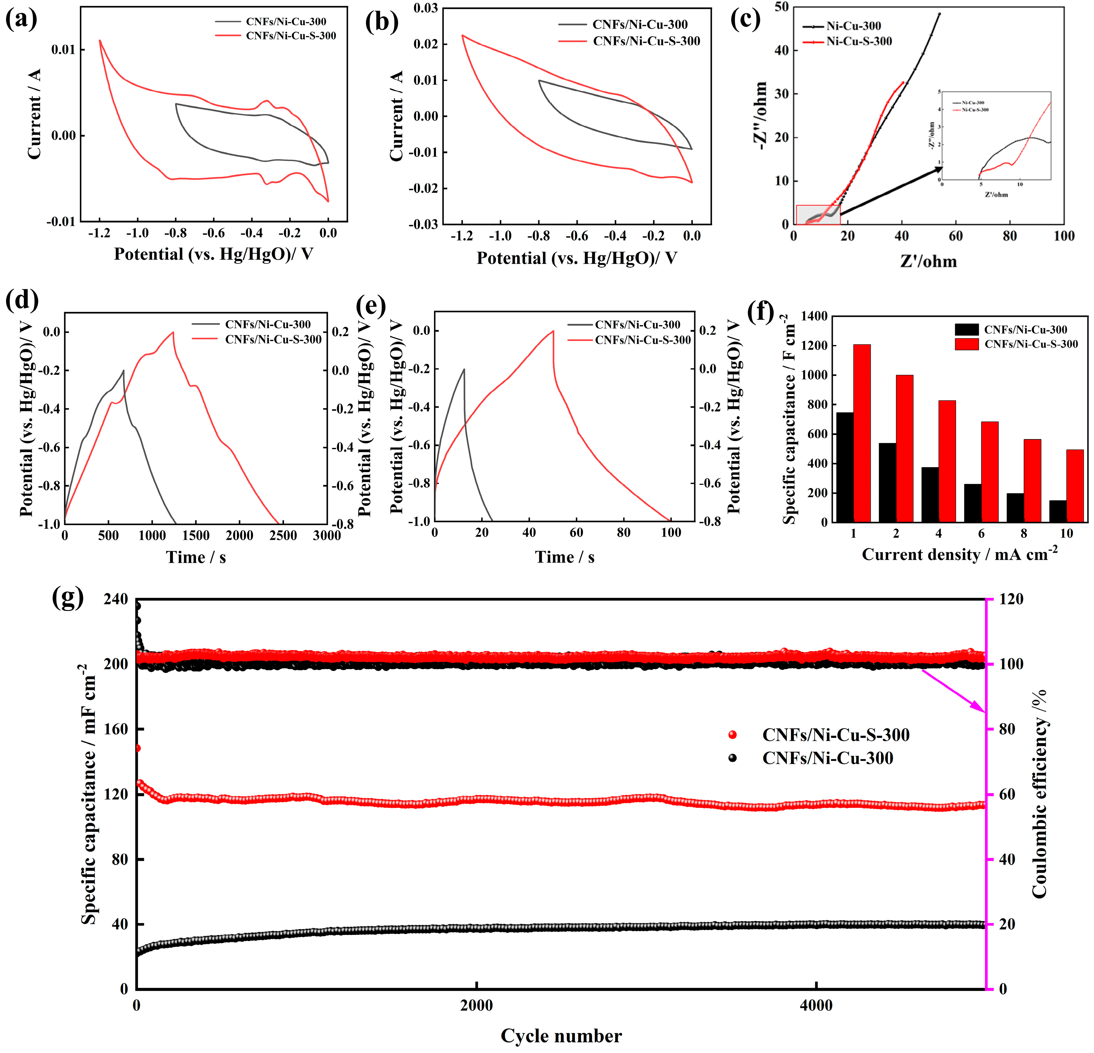
3.2. Electrochemical Performance

Figure 6a shows the CV curves for the CNFs/Ni–Cu–S–150 electrode with scanning rates of 5–25 mV s−1, and it can be seen that the overall CV curve of this electrode is shuttle-shaped without obvious redox peaks due to the low content of Ni–Cu–S nanoparticles, indicating that it is mainly a surface-controlled diffusion process. Figure 6b shows the CV curves for the CNFs/Ni–Cu–S–300 electrode with scanning rates of 5–25 mV s−1. Compared with the CNFs/Ni–Cu–S–150 electrode, with the increase in scanning rate, the redox peak current improves, and the cathode peak shifts to lower potentials, with the anode peak shifting to higher potentials, indicating significant pseudo-capacitance behavior. Figure 6c shows the CV curves of the CNFs/Ni–Cu–S–450 electrode with scanning rates of 5–25 mV s−1. With the increase in the Ni–Cu–S particle concentration, the redox peak of this electrode is more obvious, but its area is much smaller than that of the CNFs/Ni–Cu–S–300 electrode. As shown in the SEM images, the fracture of the carbon nanofiber was serious; hence, the conductivity was suppressed. Figure 6d shows the GCD curves of the CNFs/Ni–Cu–S–150 electrode with current densities of 1–10 A g−1; consistent with the CV curve display, no redox peaks appeared which is the standard capacitance behavior. Figure 6e shows the GCD curves of the CNFs/Ni–Cu–S–300 electrode with current densities of 1–10 A g−1; the redox peak appeared at the same peak position as the CV curve. The curve shape is basically symmetrical, which represents the excellent reversibility of the electrodes redox reaction, and its capacity is roughly calculated by the GCD curve, which is the best of the three. Figure 6f shows the GCD curves of the CNFs/Ni–Cu–S–450 electrode with the current densities 1–10 A g−1, and its redox peak is more obvious than the former, indicating that the electrode mainly works with pseudo-capacitive behavior operation. The reduced conductivity affects its surface diffusion, leading to its capacity reduction [37,38].
The electrochemical properties of the samples under varying gradient concentrations of the CNFs/Ni–Cu–S were compared, and Figure 7a shows the CV curves of the CNFs/Ni–Cu–S–150, CNFs/Ni–Cu–S–300, and CNFs/Ni–Cu–S–450 electrodes at a same scan rate of 5 mV s−1. At this scan rate, the area of CNFs/Ni–Cu–S–150 is the smallest relative to other two electrodes, and since its capacitive behavior is mainly controlled by surface diffusion, the polarization effect was not obvious when the voltage is close to −1 V and 0 V. The overall shape is almost a rectangular, which could be attributed to typical double-layer supercapacitors. The CNFs/Ni–Cu–S–300 has the largest area, with the redox peak appearing around −0.3 V, and the relevant electrochemical reactions can be described as follows:
C u N i 3 S 2 4 + O H C u N i 3 S 2 4 O H + e
Similarly, the same reaction occurs at the CNFs/Ni–Cu–S–450 electrode, so the peak positions are very close when the reaction occurs, and since there are more Ni–Cu–S nanoparticles on the CNFs/Ni–Cu–S–450 electrode, their redox peaks are slightly stronger. At a scan rate of 25 mV s−1, the higher the content of Ni–Cu–S nanoparticles, the less pronounced the polarization effect (Figure 7b). The redox peaks of the CNFs/Ni–Cu–S–300 electrode were significantly shifted. However, the area of the CNFs/Ni–Cu–S–300 electrode was still the largest among the three, indicating that its multiplicative performance was better than other two electrodes. Furthermore, the GCD curves of three electrodes were analyzed. Figure 7c shows the GCD curves of the corresponding electrodes at a current density of 1 mA cm−2. Both the CNFs/Ni–Cu–S–300 and CNFs/Ni–Cu–S–450 electrodes showed more obvious redox peaks which were consistent with the peak positions of the CV curves, and the capacitance of the CNFs/Ni–Cu–S–300 electrode was 1208 mF cm−2, which presented a more obvious pseudo-capacitance behavior. Figure 7d shows that the capacitance of the CNFs/Ni–Cu–S–300 electrode was higher than the CNFs/Ni–Cu–S–150 and CNFs/Ni–Cu–S–450 electrodes, and the former is due to fewer nanoparticles, while the latter is because too many nanoparticles destroy the one-dimensional carbon nanofiber structure, resulting in a decrease in ion exchange rate. The GCD curves of the CNFs/Ni–Cu–S–450 electrodes at a current density of 10 mA cm−2 show that the capacitance capacity of all three devices decreases more obviously when the current density increases to 10 mA cm−2. In comparison, it seems that the capacity of the CNFs/Ni–Cu–S–300 electrode remains at a high level after the current density increases, partly because the density of Ni–Cu–S nanoparticles is in the middle and has just reached equilibrium, and on the other hand, it is also because the electrode is a self-supporting electrode and the loss of active material is not too serious.
Figure 8a shows the comparative EIS of the CNFs/Ni–Cu–S samples. In the low frequency range, the linear slope of the CNFs/Ni–Cu–S–150 electrode is higher than that of the other two, indicating that the CNFs/Ni–Cu–S–150 electrode exhibits lower diffusion resistance and faster ion transfer rate. The semicircle of the CNFs/Ni–Cu–S–300 electrode in the high frequency range is smaller than that of the remaining two electrodes (Figure 8a), indicating that the CNFs/Ni–Cu–S–300 electrode displays lower charge transfer resistance (Rct). In addition, the equivalent series resistance (Rs) of the CNFs/Ni–Cu–S–150 electrode and the CNFs/Ni–Cu–S–300 electrode are very close to each other and are 4.50 Ω and 4.77 Ω, respectively.
The trend of the sample specific capacity with current density is provided in Figure 8b, which is based on the GCD curves in Figure 6d–f. At current densities of 1, 2, 4, 6, 8, and 10 mA cm−2, the specific capacities of the CNFs/Ni–Cu–S–150 electrode were calculated to be 656.0, 511.4, 384.0, 310.2, 260.0, and 223.7 mF cm−2, respectively. The specific capacities of the CNFs/Ni–Cu–S–300 electrode were 1208.0, 1000.0, 828.0, 682.8, 563.2, and 492.0 mF cm−2. The specific capacities of the CNFs/Ni–Cu–S–450 electrode were 725.0, 534.6, 410.4, 319.2, 256.3 and 201.2 mF cm−2. The CNFs/Ni–Cu–S–300 capacitance retention is 40.7%, indicating that this energy storage mechanism is somewhat affected at high current densities when the Faraday reaction is dominant. Figure 8c is a cycling stability test with three electrodes subjected to a current density of 10 mA cm−2 for 5000 cycles. After 5000 cycles, the CNFs/Ni–Cu–S–150 electrode, CNFs/Ni–Cu–S–300 electrode, and CNFs/Ni–Cu–S–450 electrode were 68.3%, 76.5%, and 65.7% of initial capacity, respectively. The CNFs/Ni–Cu–S–300 electrode maintains the highest capacitance retention and the most stable electrochemical performance after 5000 cycles. The CNFs/Ni–Cu–S–300 electrode and CNFs/Ni–Cu–S–450 electrode are highly symmetrical GCD curves, and reversible redox reactions can occur stably. All electrodes have high cycling stability after multiple cycles, and it can be deduced from the SEM diagram in the previous section that the lower content of Ni-Cu nanoparticles in the CNFs/Ni–Cu–S–150 electrode led to the defect being amplified after several cycles and the structure not being stable enough, which led to the decrease in cycling stability.
Figure 9a,b show the CV curves of both electrodes at scan rates of 5 mV s−1 and 25 mV s−1 and it can be seen that the voltage window of the two electrodes after sulfidation expands from −0.8 V–0 V to −1 V–0 V. Observing the redox reaction of the electrodes with both electrolytes at 1 M KOH, it can be seen that the CNFs/Ni–Cu–S–300 electrode has more redox peaks than the CNFs/Ni–Cu–300 electrode, which improves the voltage window. Comparing the CV areas of the two electrodes, the CNFs/Ni–Cu–S–300 electrode basically completely contains the CNFs/Ni–Cu–300 electrode, and the area is nearly twice that of the latter. Figure 9c compares the EIS curves of both electrodes. The CNFs/Ni–Cu–S–300 electrode has a smaller semicircle in the low frequency region, indicating a smaller charge transfer resistance [39,40]. The intersection point of the CNFs/Ni–Cu–S–300 electrode and the real axis is further forward, and its equivalent series resistance (Rs.) is also smaller. The linear slope of the CNFs/Ni–Cu–S–300 electrode in the low frequency region is larger than that of the CNFs/Ni–Cu–300 electrode, indicating that the diffusion resistance of the former is also smaller, so the ion transfer performance of the CNFs/Ni–Cu–S–300 electrode is better than the CNFs/Ni–Cu–300 electrode. As shown in Figure 9d,e, the GCD curves of the two electrodes were compared at current densities of 1 mA cm−2 and 10 mA cm−2 The capacity of the CNFs/Ni–Cu–S–300 electrode was higher than the CNFs/Ni–Cu–300 electrode whether at the high or low current density, and both electrodes had good symmetry and excellent reversibility of the redox reaction. The CNFs/Ni–Cu–S–300 electrode’s multiplicity performance is better than that of the CNFs/Ni–Cu–300 electrode.
The summary of the specific capacity of the two electrodes can be seen in Figure 9f. The CNFs/Ni–Cu–S–300 electrode is higher than the CNFs/Ni–Cu–300 electrode in terms of capacity and multiplicity performance, and the graph allows a more intuitive comparison of these. The cycling stability of the electrodes was tested (Figure 9), and the specific capacity of the CNFs/Ni–Cu–S–300 electrode was 76.5% of initial capacity for 5000 cycles at a current density of 10 mA cm−2, which is caused by the fact that the samples are obtained via reductive vulcanization, and the active material falls off after many cycles. The specific capacity of the CNFs/Ni–Cu–300 electrode was 160% of initial capacity, due to the difference in the energy storage mechanisms between electrodes at high currents. The CNFs/Ni–Cu–300 electrodes require a long time for activation to involve the pore structure inside the material in the reaction, but are very unstable during cycling, whereas CNFs/Ni–Cu–S–300 electrodes have high cycling stability. Furthermore, comparison with reported electrodes with similar material systems (as shown in Table 3) shows that our electrode, i.e., CNFs/Ni–Cu–S–300, has good specific capacity and cycling stability.

4. Conclusions

In this work, N-doped CNFs compounded with Ni–Cu–S nanoparticles were prepared by electrospinning. By doping with N elements, the electrical conductivity of CNFs was improved while ensuring a good structure. After successfully sulfurizing the Ni-Cu nanoparticles attached to surfaces of CNFs without destroying their structure, the electrochemical performance of CNFs/Ni–Cu–S was successfully enhanced. The area specific capacitance of the CNFs/Ni–Cu–S–300 electrode reached 1208 mF cm−2 at a current density of 1 mA cm−2, and the capacitance capacity is 76.5% of initial capacity after 5000 cycles, which presents an excellent cycling stability. In addition, since the electrode is self-supporting, it avoids the problems of poor adhesion of electrode materials and low utilization of active materials due to an inactive binder and conductive agent, which is a great advantage compared with conventional collectors.

Supplementary Materials

The following supporting information can be downloaded at: https://www.mdpi.com/article/10.3390/en17061449/s1, Figure S1: SEM images of CNFs/Ni-Cu-150, CNFs/Ni-Cu-300 and CNFs/Ni-Cu-450; Figure S2: SEM images of CNFs/Ni-Cu-S-150, CNFs/Ni-Cu-S-300, and CNFs/Ni-Cu-S-450; Figure S3: SEM cross-sections of CNFs/Ni-Cu-S-150, CNFs/Ni-Cu-S-300, and CNFs/Ni-Cu-S-450; Figure S4: TEM of CNFs/Ni-Cu-300 with element mapping maps; Figure S5: XPS full spectrum of CNFs/Ni-Cu-300; Figure S6: Fine spectra of elements of CNFs/Ni-Cu-300 and elemental composition ratio of CNFs-Ni-Cu-300; Figure S7: (a) N2 adsorption–desorption curves of CNFs/Ni-Cu-300, (b) pore size distribution of CNFs/Ni-Cu-300; Figure S8: Electrochemical testing of CNFs/Ni-Cu samples.

Author Contributions

Conceptualization, Y.W., Q.L. (Qiming Liu) and Y.Z.; methodology, Y.W., Y.Z. and Q.L. (Qiong Li); validation, Y.W. and Q.L. (Qiong Li) and X.F.; formal analysis, Y.W. and Q.L. (Qiong Li); investigation, G.W. and N.L.; resources, G.W. and N.L.; data curation, Y.W. and Q.L. (Qiong Li); writing—original draft preparation, Q.L. (Qiong Li) and Y.W.; writing—review and editing, Q.L. (Qiong Li), Y.W., Q.L. (Qiming Liu), S.L. and D.H.; visualization, Q.L. (Qiong Li), Y.Z. and Y.W.; supervision, Q.L. (Qiming Liu), S.L. and D.H.; project administration, Q.L. (Qiming Liu), S.L. and D.H.; funding acquisition, Q.L. (Qiming Liu), S.L. and D.H. All authors have read and agreed to the published version of the manuscript.

Funding

This work was supported by the National Natural Science Foundation of China (grant no. 61804070), the Science and Technology Projects of Gansu Province (no. 21JR7RA467), and the Fundamental Research Funds for the Central Universities (grant no. lzujbky-2023-14 and lzujbky-2022-it30).

Data Availability Statement

Data are contained within the article and Supplementary Materials.

Conflicts of Interest

The authors declare no conflicts of interest.

References

  1. Du, Y.Q.; Zhang, B.Y.; Kang, R.K.; Zhou, W.; Zhang, W.Y.; Jin, H.X.; Wan, J.Q.; Zhang, J.X.; Chen, G.W. Boron-doping-induced defect engineering enables high performance of a graphene cathode for aluminum batteries. Inorg. Chem. Front. 2022, 9, 925–934. [Google Scholar] [CrossRef]
  2. Su, Z.H.; Huang, J.H.; Wang, R.H.; Zhang, Y.; Zeng, L.X.; Zhang, Y.F.; Fan, H.S. Multilayer structure covalent organic frameworks (COFs) linking by double functional groups for advanced K plus batteries. J. Colloid. Interf. Sci. 2023, 639, 7–13. [Google Scholar] [CrossRef] [PubMed]
  3. Zhao, D.C.; Zhang, Z.; Ren, J.H.; Xu, Y.Y.; Xu, X.Y.; Zhou, J.; Gao, F.; Tang, H.; Liu, S.P.; Wang, Z.L.; et al. Fe2VO4 nanoparticles on rGO as anode material for high-rate and durable lithium and sodium ion batteries. Chem. Eng. J. 2023, 451, 138882. [Google Scholar] [CrossRef]
  4. Liang, G.; Li, X.; Wang, Y.; Yang, S.; Huang, Z.; Yang, Q.; Wang, D.; Dong, B.; Zhu, M.; Zhi, C. Building durable aqueous K-ion capacitors based on MXene family. Nano Res. Energy 2022, 1, e9120002. [Google Scholar] [CrossRef]
  5. Zhang, Y.W.; Du, H.L.; Lu, J.; Li, Z.; Lu, T.; Hu, Y.X.; Ma, Y.T. Enhanced cyclic stability of Ga2O3@PDA-C nanospheres as pseudocapacitive anode materials for lithium-ion batteries. Fuel 2023, 334, 126683. [Google Scholar] [CrossRef]
  6. Wang, Z.P.; Cheng, J.L.; Zhou, J.W.; Zhang, J.X.; Huang, H.; Yang, J.; Li, Y.C.; Wang, B. All-climate aqueous fiber-shaped supercapacitors with record areal energy density and high safety. Nano Energy 2018, 50, 106–117. [Google Scholar] [CrossRef]
  7. Fang, B.; Wei, Y.-Z.; Suzuki, K.; Kumagai, M. Surface modification of carbonaceous materials for EDLCs application. Electrochim. Acta 2005, 50, 3616–3621. [Google Scholar] [CrossRef]
  8. Yang, S.; Liu, Y.; Hao, Y.; Yang, X.; Goddard, W.A., III; Zhang, X.L.; Cao, B. Oxygen-vacancy abundant ultrafine Co3O4/graphene composites for high-rate supercapacitor electrodes. Adv. Sci. 2018, 5, 1700659. [Google Scholar] [CrossRef] [PubMed]
  9. Levitt, A.S.; Alhabeb, M.; Hatter, C.B.; Sarycheva, A.; Dion, G.; Gogotsi, Y. Electrospun MXene/carbon nanofibers as supercapacitor electrodes. J. Mater. Chem. A 2019, 7, 269–277. [Google Scholar] [CrossRef]
  10. Elseman, A.; Fayed, M.; Mohamed, S.; Rayan, D.; Allam, N.; Rashad, M.; Song, Q. A novel composite CoFe2O4@CSs as electrode by easy one-step solvothermal for enhancing the electrochemical performance of hybrid supercapacitors. ChemElectroChem 2020, 7, 526–534. [Google Scholar] [CrossRef]
  11. Pan, Z.D.; Yu, S.; Wang, L.F.; Li, C.Y.; Meng, F.; Wang, N.; Zhou, S.X.; Xiong, Y.; Wang, Z.L.; Wu, Y.T.; et al. Recent Advances in Porous Carbon Materials as Electrodes for Supercapacitors. Nanomaterials 2023, 13, 1744. [Google Scholar] [CrossRef] [PubMed]
  12. Zhang, Q.; Deng, C.; Huang, Z.; Zhang, Q.; Chai, X.; Yi, D.; Fang, Y.; Wu, M.; Wang, X.; Tang, Y. Dual-Silica Template-Mediated Synthesis of Nitrogen-Doped Mesoporous Carbon Nanotubes for Supercapacitor Applications. Small 2023, 19, 2205725. [Google Scholar] [CrossRef] [PubMed]
  13. Shen, Y.K.; Lv, Y.Y.; Chi, H.Z.; Xi, J.H.; Xiong, Q.W.; Qin, H.Y. All-Solid-State Supercapacitor with High Volumetric Energy for Flexible Application. J. Electrochem. Soc. 2019, 166, A2797–A2804. [Google Scholar] [CrossRef]
  14. Orlando, J.D.; Lima, R.M.A.P.; Li, L.; Sydlik, S.A.; de Oliveira, H.P. Electrochemical Performance of N-Doped Carbon-Based Electrodes for Supercapacitors. ACS Appl. Electron. Mater. 2022, 4, 5040–5054. [Google Scholar] [CrossRef]
  15. Wang, H.W.; Yi, H.; Chen, X.; Wang, X.F. Asymmetric supercapacitors based on nano-architectured nickel oxide/graphene foam and hierarchical porous nitrogen-doped carbon nanotubes with ultrahigh-rate performance. J. Mater. Chem. A 2014, 2, 3223–3230. [Google Scholar] [CrossRef]
  16. Cheng, Y.; Zhai, M.M.; Hu, J.B. The fabrication of NiCuS from NiCu film on nickel foam for methanol electrooxidation and supercapacitors. Appl. Surf. Sci. 2019, 480, 505–513. [Google Scholar] [CrossRef]
  17. Dai, T.T.; Cai, B.; Yang, X.J.; Jiang, Y.; Wang, L.Y.; Wang, J.S.; Li, X.S.; Lü, W. Asymmetric supercapacitors based on SnNiCoS ternary metal sulfide electrodes. Nanotechnology 2023, 34, 225401. [Google Scholar] [CrossRef]
  18. Beknalkar, S.A.; Teli, A.M.; Shin, J.C. Current innovations and future prospects of metal oxide electrospun materials for supercapacitor technology: A review. J. Mater. Sci. Technol. 2023, 166, 208–233. [Google Scholar] [CrossRef]
  19. Zhao, D.H.; Wang, H.; Bai, Y.; Yang, H.; Song, H.F.; Li, B.H. Preparation of Advanced Multi-Porous Carbon Nanofibers for High-Performance Capacitive Electrodes in Supercapacitors. Polymers 2023, 15, 213. [Google Scholar] [CrossRef] [PubMed]
  20. Zhao, X.; Sajjad, M.; Zheng, Y.Q.; Zhao, M.M.; Li, Z.J.; Wu, Z.Y.; Kang, K.; Qiu, L. Covalent organic framework templated ordered nanoporous C as stable energy efficient supercapacitor electrode material. Carbon 2021, 182, 144–154. [Google Scholar] [CrossRef]
  21. Yadav, D.; Amini, F.; Ehrmann, A. Recent advances in carbon nanofibers and their applications—A review. Eur. Polym. J. 2020, 138, 109963. [Google Scholar] [CrossRef]
  22. Azwar, E.; Wan Mahari, W.A.; Chuah, J.H.; Vo, D.V.N.; Ma, N.L.; Lam, W.H.; Lam, S.S. Transformation of biomass into carbon nanofiber for supercapacitor application—A review. Int. J. Hydrogen Energy 2018, 43, 20811–20821. [Google Scholar] [CrossRef]
  23. Kshetri, T.; Tran, D.T.; Nguyen, D.C.; Kim, N.H.; Lau, K.-T.; Lee, J.H. Ternary graphene-carbon nanofibers-carbon nanotubes structure for hybrid supercapacitor. Chem. Eng. J. 2020, 380, 122543. [Google Scholar]
  24. Luo, W.; Xue, H. The synthesis and electrochemical performance of NiCo2O4 embedded carbon nanofibers for high-performance supercapacitors. Fuller. Nanotub. Carbon Nanostruct. 2019, 27, 189–197. [Google Scholar] [CrossRef]
  25. Fan, P.Z.; Ye, C.W.; Xu, L. One-dimensional nanostructured electrode materials based on electrospinning technology for supercapacitors. Diam. Relat. Mater. 2023, 134, 109803. [Google Scholar] [CrossRef]
  26. Thejas Prasannakumar, A.; Mohan, R.R.; V, M.; Varma, S.J. Progress in Conducting Polymer-Based Electrospun fibers for Supercapacitor Applications: A Review. ChemistrySelect 2023, 8, e202203564. [Google Scholar] [CrossRef]
  27. Altin, Y.; Bedeloglu, A.C. Polyacrylonitrile/polyvinyl alcohol-based porous carbon nanofiber electrodes for supercapacitor applications. Int. J. Energ. Res. 2021, 45, 16497–16510. [Google Scholar] [CrossRef]
  28. Zhu, H.; Yu, D.; Zhang, S.; Chen, J.; Wu, W.; Wan, M.; Wang, L.; Zhang, M.; Du, M. Morphology and structure engineering in nanofiber reactor: Tubular hierarchical integrated networks composed of dual phase octahedral CoMn2O4/carbon nanofibers for water oxidation. Small 2017, 13, 1700468. [Google Scholar] [CrossRef] [PubMed]
  29. Ismar, E.; Karazehir, T.; Ates, M.; Sarac, A.S. Electrospun carbon nanofiber web electrode: Supercapacitor behavior in various electrolytes. J. Appl. Polym. Sci. 2018, 135, 45723. [Google Scholar] [CrossRef]
  30. Sun, J.; Chen, Y.-R.; Huang, K.; Li, K.; Wang, Q. Interfacial electronic structure and electrocatalytic performance modulation in Cu0.81Ni0.19 nanoflowers by heteroatom doping engineering using ionic liquid dopant. Appl. Surf. Sci. 2020, 500, 144052. [Google Scholar]
  31. Huang, Q.; Li, C.; Tu, Y.; Jiang, Y.; Mei, P.; Yan, X. Spinel CoFe2O4/carbon nanotube composites as efficient bifunctional electrocatalysts for oxygen reduction and oxygen evolution reaction. Ceram. Int. 2021, 47, 1602–1608. [Google Scholar]
  32. Li, T.F.; Lv, Y.J.; Su, J.H.; Wang, Y.; Yang, Q.; Zhang, Y.W.; Zhou, J.C.; Xu, L.; Sun, D.M.; Tang, Y.W. Anchoring CoFe2O4 Nanoparticles on N-Doped Carbon Nanofibers for High-Performance Oxygen Evolution Reaction. Adv. Sci. 2017, 4, 1700226. [Google Scholar] [CrossRef] [PubMed]
  33. Wang, J.G.; Jin, D.D.; Zhou, R.; Shen, C.; Xie, K.Y.; Wei, B.Q. One-step synthesis of NiCoS ultrathin nanosheets on conductive substrates as advanced electrodes for high-efficient energy storage. J. Power Sources 2016, 306, 100–106. [Google Scholar] [CrossRef]
  34. Lu, Y.; Zhang, Z.W.; Liu, X.M.; Wang, W.X.; Peng, T.; Guo, P.F.; Sun, H.B.; Yan, H.L.; Luo, Y.S. NiCoS/carbon nanotube nanocomposites with a chain-like architecture for enhanced supercapacitor performance. Crystengcomm 2016, 18, 7696–7706. [Google Scholar] [CrossRef]
  35. Wu, D.; Zhang, W.; Cheng, D. Facile synthesis of Cu/NiCu electrocatalysts integrating alloy, core–shell, and one-dimensional structures for efficient methanol oxidation reaction. ACS Appl. Mater. Interfaces 2017, 9, 19843–19851. [Google Scholar] [CrossRef] [PubMed]
  36. Fang, X.R.; Cheng, P.; Sun, K.; Fu, Y.J.; Liu, D.Q.; He, D.Y. Zn-N Codoped Carbon Nanofiber Interlayer for Anchor and Catalysis of Polysulfides in Lithium-Sulfur Batteries. ACS Appl. Energ. Mater. 2022, 5, 8189–8197. [Google Scholar] [CrossRef]
  37. William, J.J.; Babu, I.M.; Muralidharan, G. Nickel bismuth oxide as negative electrode for battery-type asymmetric supercapacitor. Chem. Eng. J. 2021, 422, 130058. [Google Scholar] [CrossRef]
  38. Shen, B.S.; Guo, R.S.; Lang, J.W.; Liu, L.; Liu, L.Y.; Yan, X.B. A high-temperature flexible supercapacitor based on pseudocapacitive behavior of FeOOH in an ionic liquid electrolyte. J. Mater. Chem. A 2016, 4, 8316–8327. [Google Scholar] [CrossRef]
  39. Qi, J.Q.; Chang, Y.; Sui, Y.W.; He, Y.Z.; Meng, Q.K.; Wei, F.X.; Zhao, Y.L.; Jin, Y.X. Facile Construction of 3D Reduced Graphene Oxide Wrapped NiS Nanoparticles on Ni Foam for High-Performance Asymmetric Supercapacitor Electrodes. Part. Part. Syst. Charact. 2017, 34, 1700196. [Google Scholar] [CrossRef]
  40. Hu, W.; Chen, R.Q.; Xie, W.; Zou, L.L.; Qin, N.; Bao, D.H. CoNiS Nanosheet Arrays Supported on Nickel Foams with Ultrahigh Capacitance for Aqueous Asymmetric Supercapacitor Applications. ACS Appl. Mater. Interfaces 2014, 6, 19318–19326. [Google Scholar] [CrossRef]
  41. Fan, P.; Xu, L. Core-Shell Carbon Nanofibers@Ni(OH)2/NiO Composites for High-Performance Asymmetric Supercapacitors. Materials 2022, 15, 8377. [Google Scholar] [CrossRef] [PubMed]
  42. Liu, Y.; Jiang, G.; Sun, S.; Xu, B.; Zhou, J.; Zhang, Y.; Yao, J. Decoration of carbon nanofibers with NiCo2S4 nanoparticles for flexible asymmetric supercapacitors. J. Alloys Compd. 2018, 731, 560–568. [Google Scholar] [CrossRef]
  43. Li, B.; Tian, Z.; Li, H.; Yang, Z.; Wang, Y.; Wang, X. Self-supporting graphene aerogel electrode intensified by NiCo2S4 nanoparticles for asymmetric supercapacitor. Electrochim. Acta 2019, 314, 32–39. [Google Scholar]
  44. Xu, L.; Wang, W.; Liu, Y.; Liang, D. Nanocellulose-Linked MXene/Polyaniline Aerogel Films for Flexible Supercapacitors. Gels 2022, 8, 798. [Google Scholar] [PubMed]
Figure 1. Schematic diagram of the preparation process of Ni–Cu–S/CNFs.
Energies 17 01449 g001
Figure 2. XRD images of (a) CNFs/Ni–Cu–150, CNFs/Ni–Cu–300, and CNFs/Ni–Cu–450 and (b) CNFs/Ni–Cu–S–300.
Energies 17 01449 g002
Figure 3. (a) SEM image of CNFs/Ni–Cu–300; (b) SEM image of CNFs/Ni–Cu–S–300; (c) TEM image of CNFs/Ni–Cu–300; (d) mapping image of CNFs/Ni–Cu–S–300; (e) TEM image of CNFs/Ni–Cu–S–300.
Energies 17 01449 g003
Figure 4. (af) XPS images of CNFs/Ni–Cu–S–300: full spectrum (a), fine spectrum of C 1s (b), N 1s (c), Ni 2p (d), Cu 2p (e), S 2p (f), and (g) elemental composition ratio of CNFs-Ni–Cu–S–300 samples.
Energies 17 01449 g004
Figure 5. (a) N2 adsorption–desorption curves and (b) pore size distribution of CNFs/Ni–Cu–S–300 samples.
Energies 17 01449 g005
Figure 6. Electrochemical testing of CNFs/Ni–Cu–S samples, (a,d) CNFs/Ni–Cu–S–150, (b,e) CNFs/Ni–Cu–S–300, (c,f) CNFs/Ni–Cu–S–450.
Energies 17 01449 g006
Figure 7. CNFs/Ni–Cu–S–150, CNFs/Ni–Cu–S–300, and CNFs/Ni–Cu–S–450 electrodes at (a) CV curves for a scan rate of 5 mV s−1, (b) CV curves for a scan rate of 25 mV s−1, (c) GCD curves for a current density of 1 mA cm−2, and (d) GCD curves for a current density of 10 mA cm−2.
Energies 17 01449 g007
Figure 8. Comparison of the electrochemical properties of CNFs/Ni–Cu–S samples: (a) EIS curves; (b) calculated specific capacitance at different current densities; (c) 5000 charge/discharge cycles at a current density of 10 mA cm−2.
Energies 17 01449 g008
Figure 9. Comparison of CNFs/Ni–Cu–S–300 electrode and CNFs/Ni–Cu–300 electrode: CV at 5 mV s−1 (a) and 25 mV s−1 (b); EIS (c); GCD at 1 mA cm−2 (d) and 10 mA cm−2 (e); rate performance (f); cyclic stability at 10 mA cm−2 (g).
Energies 17 01449 g009
Table 1. Samples obtained by different extra concentration for CNFS/Ni–Cu–S.
SamplePre-Oxidation
Temperature
[°C]
Carbonization
Temperature
[°C]
Vulcanization Temperature
[°C]
Ni(NO3)2·6H2O Addition Amount [mg]Cu(NO3)2·3H2O Addition Amount [mg]
NCS/CNFs-150230800550150150
NCS/CNFs-300230800550300300
NCS/CNFs-450230800550450450
Table 2. Specific surface area and pore structure of CNFs/Ni-Cu-300 and CNFs/Ni–Cu–S–300.
SampleBET Surface Area
(m2 g−1)
BJH Desorption Cumulative Surface Area
(m2 g−1)
Total Pore Volume
(cm3 g−1)
BJH Desorption Cumulative Volume
(cm3 g−1)
Average
Pore Diameter
(nm)
BJH Desorption Median Pore Diameter
(nm)
CNFs/Ni–Cu–30042.60924.3590.0080.0596.0659.762
CNFs/Ni–Cu–S–300371.06354.2810.1490.0862.5626.361
Table 3. Capacitances and cycling stabilities of the electrode with the similar material systems.
Electrode MaterialsElectrolyteC/Current DensityCapacity Retention Rate/Cycle Number
NiCo2O4-CNFs [24]6 M KOH836 F g−1/5 A g−180.9%/2000 cycles
CNFs@Ni(OH)2/NiO [41]3 M KOH695 F g−1/1 A g−177%/2000 cycles
NiCo2S4@CNFs [42]3 M KOH527.8 F g−1/0.2 A g−190%/3000 cycles
NiCo2S4/GA [43]3 M KOH704.34 F g−1/1 A g−180.3%/1500 cycles
MXene/CNF–PANI [44]3 M H2SO4327 F g−1/3 mA cm−284.1%/3000 cycles
CNFs/Ni–Cu–S–300 (This work)1 M KOH1208 mF cm−2/1 mA cm−276.5%/5000 cycles
Disclaimer/Publisher’s Note: The statements, opinions and data contained in all publications are solely those of the individual author(s) and contributor(s) and not of MDPI and/or the editor(s). MDPI and/or the editor(s) disclaim responsibility for any injury to people or property resulting from any ideas, methods, instructions or products referred to in the content.

