Article

Topological Structure and Control Strategy of E-UPFC

1
School of Electrical Engineering, Northeast Electric Power University, Jilin 132012, China
2
State Grid Jilin Electric Power Co., Ltd., Siping Power Supply Company, Siping 136000, China
*
Author to whom correspondence should be addressed.
Energies 2024, 17(6), 1411; https://doi.org/10.3390/en17061411
Submission received: 22 January 2024 / Revised: 10 March 2024 / Accepted: 13 March 2024 / Published: 15 March 2024
(This article belongs to the Section F: Electrical Engineering)

Abstract

:
This article proposes a unified power flow controller with energy (E-UPFC) installed at the renewable energy grid connection node of the transmission network. Compared with other unified power flow controllers (UPFCs), the proposed E-UPFC can not only regulate the power flow on its connected transmission lines, but also suppress the power fluctuations of grid-connected nodes injected with large-scale renewable energy. At the same time, with the installation position of E-UPFC transferred from the transmission line to the node, the original stiff node can be transformed into a flexible node that can regulate the injected power flexibly. First, the PV grid-connected system with E-UPFC is introduced, and its principle of power flow regulation is detailed. In addition, the topology, mathematical modeling, and control strategies of E-UPFC are discussed. Finally, the E-UPFC is applied to the IEEE 3-generator 9-bus system with large-scale renewable energy integration in Matlab/Simulink in order to verify the correctness and feasibility of E-UPFC and its control strategies.

1. Introduction

In recent years, large-scale renewable energy, mainly composed of PV and wind power, has been continuously integrated into the transmission network. Due to the randomness and volatility of renewable energy, and the limited transmission capacity of power lines in the transmission network, the problems of insufficient absorption of renewable energy and the low power flow adjustability of lines have become increasingly serious, and have threatened the stable operation of the power system [1,2,3,4]. Therefore, flexible AC transmission systems (FACTS) have gradually become the focus of many scholars’ research in order to improve the operation capacity of the transmission network. And as an effective method of flexible regulation of power flow, it can significantly improve the transmission congestion and voltage regulation difficulties of the power grid so as to improve the reliability and operation flexibility of the transmission network [5,6].
Among various FACTS converters, there are static synchronous compensator (STATCOM), static synchronous series compensator (SSSC), UPFC, and other transformation devices [7,8]. The parallel FACTS devices can compensate reactive power, stabilize bus voltage, and improve system operation stability; for example, STATCOM can adjust its output reactive power through reactance, but it cannot effectively regulate the active power [9,10]. At the same time, the series FACTS devices can adjust line voltage, reduce line loss, and improve line transmission capacity; for example, SSSC can realize the functions of active power flow regulation, three-phase asymmetric compensation, harmonic suppression, etc. [11].
Therefore, series parallel hybrid FACTS devices such as UPFC were proposed in [6,12] in order to have the functions of parallel and series FACTS devices at the same time. The main function of the UPFC is to control the flow of real and reactive power by injecting a voltage in series with the transmission line. Both the magnitude and the phase angle of the voltage can vary independently. The UPFC combines a DC link capacitor with the series converter and the parallel converter. And the basic control for the UPFC is such that the series converter controls the transmission line’s real/reactive power flow and the shunt converter controls the bus voltage/parallel reactive power and the DC link capacitor [13]. The UPFC composed of a modular multilevel converter (MMC) was proposed in [14], which adopted a nonlinear strategy based on passive sliding mode variable structure control. A UPFC control strategy based on d-q axis theory was proposed in [15], which exhibited fast response performance in power flow control.
Due to the limited capacity of the DC link capacitor in UPFC, it is not possible to supply controllable active power for an extensive duration [16]. A new approach was proposed to enhance the regulation effect of the device in FACTS by integrating an energy storage system (ESS) in [17,18]. A UPFC with superconducting magnetic energy storage was proposed to regulate the power flow of the transmission line and improve the power transfer capability of the UPFC in [19]. And [20] proposed a static synchronous compensation device with ESS, which could effectively suppress the output fluctuations of renewable energy, expand the operation range of FACTS, and make the transmission more flexible, but it did not have the ability to regulate the power flow on the transmission line effectively. However, the above studies with ESS only achieved power flow regulation, and the utilization rate of ESS was not high.
At present, with the increasing proportion of renewable energy in the transmission network year by year, the power fluctuations caused by renewable energy injected into the grid cannot be ignored. And it has been proposed to connect the UPFC between the grid-connected renewable energy system and the main grid so as to realize the smooth integration of renewable energy into the grid in [21]. As the traditional UPFC is often installed in the transmission line of the distribution network, as shown in Figure 1, it is limited by the installation location and cannot regulate the injection power of renewable energy at the grid-connected node. In this paper, E-UPFC is installed at the renewable energy grid connection node of the transmission network, as shown in Figure 2. And the original stiff node is transformed into the flexible node through transformation, while the ESS is used to suppress the power fluctuations of renewable energy at the node and regulate the power flow on its connected transmission lines.
This article proposes an E-UPFC installed at the renewable energy grid connection node of the transmission network, which can suppress the power fluctuations of large-scale renewable energy and regulate the power flow on transmission lines flexibly. The rest of this article is organized as follows. In Section 2, the PV grid-connected system with E-UPFC is introduced, and the principles of power flow regulation are analyzed in detail. In Section 3, the topology and mathematical modeling of E-UPFC are presented. Then, the control strategy of E-UPFC is designed in Section 4. And the simulation results verify the correctness and feasibility of the proposed E-UPFC topology in Section 5. Finally, Section 6 concludes this article.

2. PV Grid-Connected System with E-UPFC

The schematic diagram of the PV grid-connected system with E-UPFC is shown in Figure 2. E-UPFC consists of double-winding power transformer TET, FE-MMC, and BE-MMC. FE-MMC is connected to the line in parallel through transformer TET1 and connected to Bus 1, which can suppress the power fluctuations of large-scale PV grid-connected system connected to Bus 1. And BE-MMC is connected to the transmission network through transformer TET2 in series and connected to bus 2, which can regulate the power flow on the transmission lines connected to bus 2. On this basis, FE-MMC and BE-MMC are connected back-to-back and share the same DC bus, and the ESS is connected in parallel with the DC side capacitor through the bidirectional DC-DC converter in order to provide an energy buffer for FE-MMC and BE-MMC.
When there is an excess of generated PV power after the photovoltaic output power meets the load demand of the grid, it is necessary to control the ESS to absorb the redundant power, and the power flows from the AC bus to the ESS through FE-MMC at this time. When the PV output power is not enough to meet the load demand of the grid, it is necessary to control the discharge of the ESS to compensate for the lack of power, and the power flows from the ESS to the AC bus through FE-MMC. Hence, the fluctuation components in the PV output power can be suppressed while the ESS is charged and discharged.
Specifically, with the large-scale renewable energy connected to the power grid, FE-MMC is equivalent to a controllable current source, which can effectively suppress the power fluctuations caused by intermittent and uncertain output of renewable energy. FE-MMC is equivalent to a controllable voltage source, which is equivalent to inserting an adjustable voltage in series in the line to actively support the voltage and regulate the power flow. At the same time, the ESS can control the DC side capacitor voltage stability through the power throughput, ensure the decoupling of the FE-MMC and BE-MMC, and enable them to exchange line power independently.
As the main part of the power suppression function, FE-MMC combines the basic idea of suppressing power fluctuations with the ESS to absorb and compensate for the fluctuation components of the renewable energy output through charge and discharge, which is expressed as:
P s = P w P o
where Pw is the output power of the PV grid-connected system with fluctuation components, Po is the reference value of the PV grid-connected power, and Ps is the power provided by the ESS to suppress power fluctuations.
FE-MMC is equivalent to a controllable voltage source, and the schematic diagram for realizing power flow regulation is shown in Figure 3. In Figure 3, UM and UN represent the voltages at sides M and N, respectively; IM and IN represent the currents of sides M and N, respectively; USC represents the equivalent series compensation voltage of BE-MMC; Si is the equivalent load of the branch line I; and Zj is the line impedance of the ring network j. If the influence of USC is not considered, the output power of side M can be calculated as follows:
S ˜ M = i = 1 n ( S ˜ i j = i + 1 n + 1 Z j * ) Z Σ + U ˙ M ( U ˙ M U ˙ N ) Z Σ
where ZΣ is the total impedance of the loop network, ZΣ = RΣ + jXΣ.
After using the controllable voltage USC generated by BE-MMC in series into the line at side M, the composite power output at side M can be expressed as:
S ˜ M = i = 1 n ( S ˜ i j = i + 1 n + 1 Z j * ) Z Σ + U ˙ M ( U ˙ M + U ˙ SC U ˙ N ) Z Σ
It is assumed that the bus voltages at both sides are constant and the load is a constant power load. The series compensation voltage at side M can directly control the output power of this side, and its relationship can be expressed as:
Δ S ˜ M = S ˜ M S ˜ M = U ˙ M U ˙ SC Z Σ
The relationship between the variation in active power ΔPM at side M and the series compensation voltage USC (USC = USCx + jUSCy) can be expressed as:
Δ P M = U M R Σ 2 + X Σ 2 ( R Σ U SCx + X Σ U SCy )
where ΔPM is the adjustment amount of active power at side M. Moreover, the relationship between reactive power variation ΔQM and series compensation voltage USC can be expressed as:
Δ Q M = U M R Σ 2 + X Σ 2 ( X Σ U SCx R Σ U SCy )
where ΔQM is the reactive power adjustment amount at side M, so BE-MMC changes the amount of power adjustment by c changing the compensation voltage connected in series in the transmission line so as to regulate the power flow.

3. Topology and Mathematical Modeling of E-UPFC

The power electronic converters in E-UPFC include FE-MMC, BE-MMC, and bidirectional DC/DC converters connected to the ESS. The FE-MMC is used to suppress fluctuations in renewable energy, BE-MMC is used to regulate power flow on transmission lines, and both FE-MMC and BE-MMC adopt MMC topology structures. Meanwhile, the bidirectional DC/DC converter for the ESS mainly provides power buffering for FE-MMC and BE-MMC, and it adopts a DC transformer (DCT) topology structure. Therefore, the topology design methods of FE-MMC, BE-MMC, and DCT for ESS are introduced in this section, which include the topology structure and the equivalent averaging model.

3.1. Topology and Equivalent Average Model of FE-MMC and BE-MMC

The MMC topology is adopted by both FE-MMC and BE-MMC, and a topology diagram of MMC and its half bridge (HB) submodule is shown in Figure 4. MMC has basic double ports of medium-voltage AC (MVAC) and medium-voltage DC (MVDC). In Figure 4, it is assumed that there are 2n submodules (SMs) in each phase, with an average of n SMs distributed in the upper or lower bridge. Ro and Lo are the resistance and inductance of each phase bridge arm, respectively, while Lac is the filtering inductance. vsj is the AC side voltage of phase j, vpj and vnj are the j phase voltages of the upper and lower bridge arms; Udc is the MVDC side output voltage; ipj and inj are the j phase voltages of the upper and lower bridge arms; ivj is the j phase output current of the MVAC side; and icirj is the internal circulating current of each phase (j = a, b, c).
According to Kirchhoff’s Voltage Law (KVL), the equation for the upper and lower bridge arm circuits of each phase of MMC can be expressed as:
u s j + L a c d i v j d t + u p j + R 0 i p j = U dc / 2 u s j + L a c d i v j d t u n j R 0 i p j = U dc / 2   ( j = a , b , c )
To further simplify the analysis, according to [22,23], the following three variables can be expressed as:
u d i f f j = 1 2 ( u n j u p j ) u c o m j = 1 2 ( u p j + u n j ) i c i r j = 1 2 ( u p j + u n j )   ( j = a , b , c )
where udiffj represents the differential-mode voltage in phase j of MMC, and ucomj represents the common-mode voltage in phase j of MMC.
According to Equation (7), the AC side average model and DC side average model of MMC can be calculated as follows:
( L a c + L o / 2 ) d i v j d t + R o 2 i v j = u s j + u d i f f j ) L o d i c i r j d t + R o i c i r j = U d c / 2 u c o m j
where Lac is the equivalent line inductance and Lo is filter inductance.
The average models of equivalent circuits on both the AC and DC sides of MMC are shown in Figure 5.

3.2. Topology and Equivalent Average Model of DCT

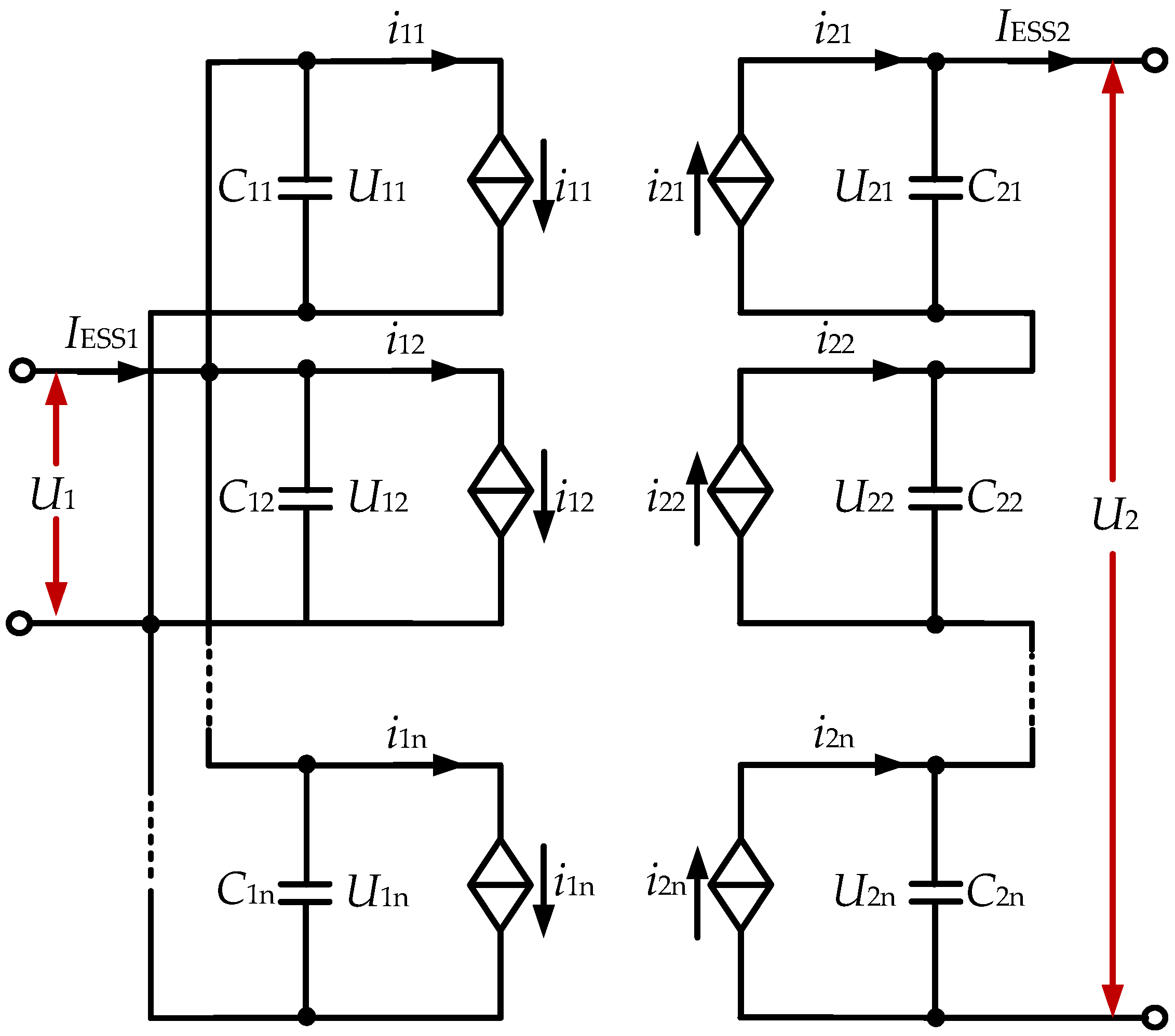
The DCT consists of dual-active bridge (DAB) converters, with its low-voltage side connected to the ESS and its medium-voltage side connected parallel to the DC capacitor between the FE-MMC and the BE-MMC. The topology of the DCT is shown in Figure 6, and each DAB converter is connected in parallel on the low-voltage side and in series on the medium-voltage side of the DCT.
In Figure 6, a DAB converter consists of a low-voltage H-bridge (LV-HB) converter, a medium-voltage H-bridge (MV-HB) converter, and a high-frequency transformer (HFT). U1 and U2 are the voltages of the LV side and MV side; u1 and u2 are the square wave output voltage of the LV-HB converter and MV-HB converter when the duty cycle is 50%; i1 and i2 are the LV side and MV side currents of HFT; C1 and C2 are the regulated capacitors at the low-voltage side and high-voltage side of the DAB; k is the HFT transformation ratio; and L is the leakage inductance of HFT. Meanwhile, the LV-HB converter and MV-HB converter output square wave voltages with different phases and a duty cycle of 50% according to the phase shift control in each DAB, and the leakage inductance of the HFT is excited by the voltage difference to generate a high-frequency current.
It is assumed that the DCT includes n DABs. According to [24], the output power PDABx of the x-th DAB unit (x = 1, 2, …, n) in a single switching cycle can be expressed as:
P D A B x = k x U 1 U 2 x D x ( 1 D x ) 2 f s L x
where U2x is the output voltage of the x-th DAB, Dx is the phase-shift duty cycle of the x-th DAB, fs is the operating frequency of the x-th DAB, and Lx is the equivalent leakage inductance of the x-th DAB unit converted to the MV side.
According to [25], the equivalent average-value model of DCT with n DABs is established, as shown in Figure 7.
As shown in Figure 7, according to [26], in a single switching cycle, i1x is the average value of the LV side and MV side currents of the HFT in the x-th DAB, and IESS is the output current of the ESS. And according to Equation (10), i1x and i2x can be expressed as follows:
i 1 x = k x U 2 x D x ( 1 D x ) 2 f s L x i 2 x = k x U 1 D x ( 1 D x ) 2 f s L x ( x = 1 , 2 , , n )
According to the equivalent average-value model in Figure 7, using KVL and Kirchhoff’s current law, the relationship between i1x and IESS is as follows:
x = 1 n C 1 n d U 1 d t = x = 1 n i 1 n I E S S = k x 2 f s x = 1 n U 2 x D x ( 1 D x ) L x I E S S

4. Control Strategy of E-UPFC

In this section, the control strategies of FE-MMC, BE-MMC, and DCT are designed to ensure the safe and stable operation of E-UPFC. FE-MMC achieves power control by controlling the current, BE-MMC achieves power control by controlling the voltage, and DCT stabilizes the voltage of the MVDC bus. The detailed control strategy is introduced as follows.

4.1. Control Strategy of FE-MMC

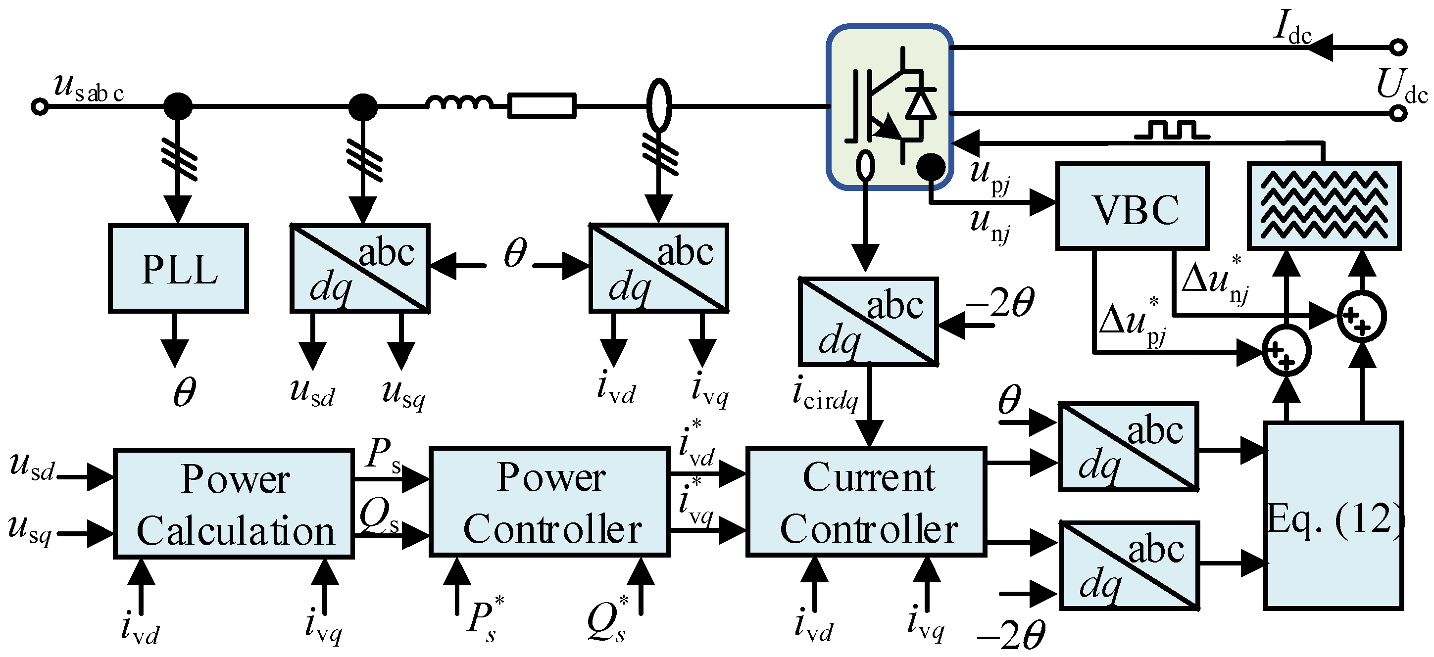
The MVAC port of FE-MMC is connected in parallel to the 35 kV bus through the step-up transformer, and its main function is to suppress the power fluctuations of new energy generation. The control target is the power of the MVAC port. The specific control strategy is shown in Figure 8, which mainly includes dq transformation, power calculation, an outer loop power controller, an inner loop current controller (including circulating current suppression) and a capacitor voltage balance controller (VBC). In Figure 8, usd is the d-axis voltage of usj after dq transformation. usq is the q-axis voltage of usj after dq transformation. ivd is the d-axis current of ivj after dq transformation. ivq is the q-axis current of ivj after dq transformation. Ps and Qs are the three-phase active power and reactive power, respectively. Ps* and Qs* are the reference values of three-phase active power and reactive power, respectively. ivd* and ivq* are the current reference values of the d-axis and q-axis, respectively. icirdq is the d-axis and q-axis circulating current icirj after dq transformation. ∆upj and ∆unj are the capacitance voltage correction of each SM, respectively.
The expressions for upj and unj can be obtained from Equation (7), as shown in Equation (12).
u p j * = u com j * u diff j * u n j * = u com j * + u diff j *

4.2. Control Strategy of BE-MMC

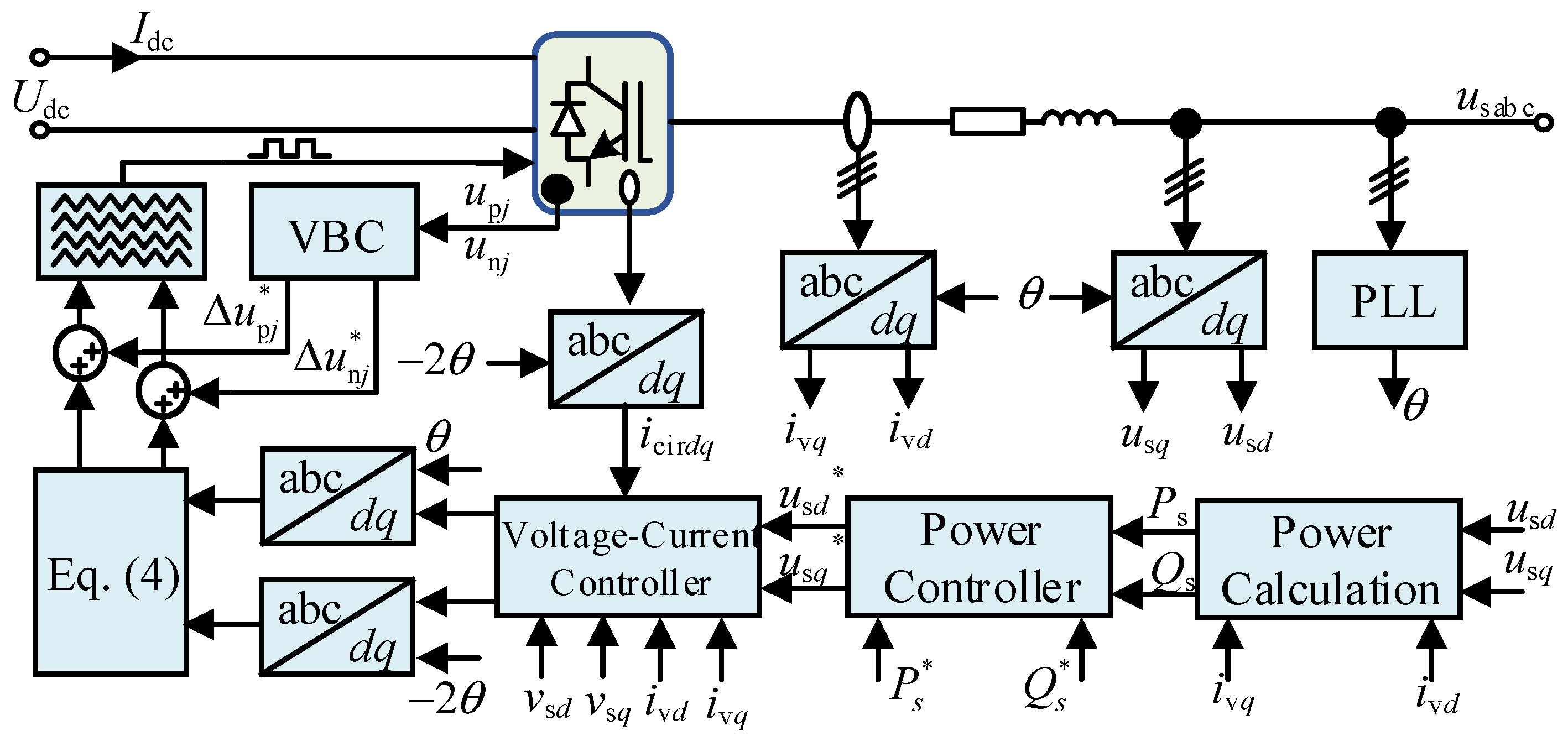
The MVAC port of BE-MMC is connected in series to the 220 kV bus through a step-up transformer, and its main function is power flow regulation. Its control target is the voltage of MVAC port. The specific control strategy is shown in Figure 9, mainly including dq conversion, power calculation, an outer loop voltage controller, an inner loop current controller (including circulating current suppression), and capacitor VBC. The difference from FE-MMC control is that the BE-MMC power control loop obtains a voltage reference value, while the FE-MMC inner loop current controller is replaced by a voltage current dual loop controller.

4.3. Control Strategy of DCT

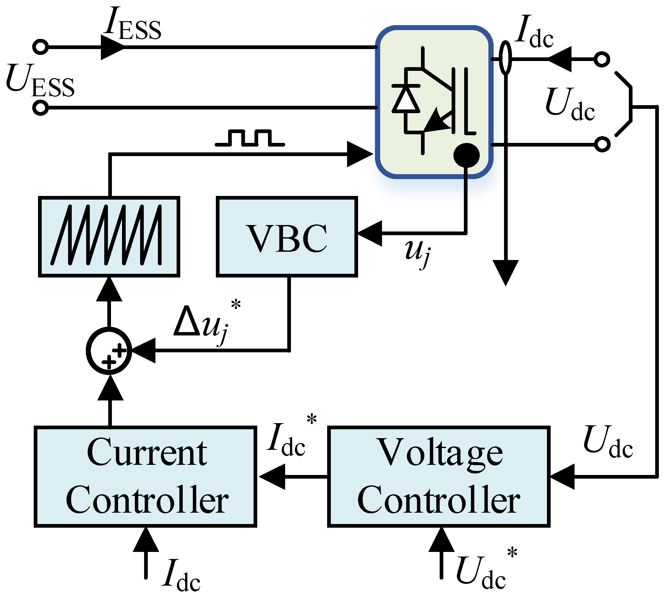
The low-voltage side of DCT is connected with energy storage, and the high-voltage side is connected with the DC bus of BTB-MMC. Its main function is to stabilize the DC bus voltage, so its control goal is DC bus voltage. The energy storage realizes adaptive charge and discharge through the power control of FE-MMC and BE-MMC. The specific control strategy is shown in Figure 6, which mainly includes the MVDC voltage controller, MVDC current controller, and capacitor VBC at the series side of the DAB module. In Figure 10, Udc is the MVDC voltage, Idc is the MVDC current, UESS is the energy storage voltage, and IESS is the energy storage current.

5. Simulation Verification

In this article, the simulation of the E-UPFC applied to the IEEE 3-generator 9-bus system with large-scale renewable energy integration is established in MATLAB/Simulink. This section verifies the effectiveness of the proposed E-UPFC topology and control strategy. As shown in Figure 11, the large-scale PV grid-connected system is boosted by 35 kV through TG, and then connected to the transmission network at bus 5 through E-UPFC. It is assumed that the transformation ratio of TET is 35/220 kV, the transformation ratio of TET1 is 10/35 kV, and the transformation ratio of TET2 is 10/10 kV. S is a bypass switch that can control whether the power electronic converters of E-UPFC are connected to the system. When the S is closed, E-UPFC works in power suppression mode to stabilize the fluctuations of renewable energy power. And when the S is off, E-UPFC works in power regulation mode to regulate the power flow of the transmission network.

5.1. Power Suppression Mode

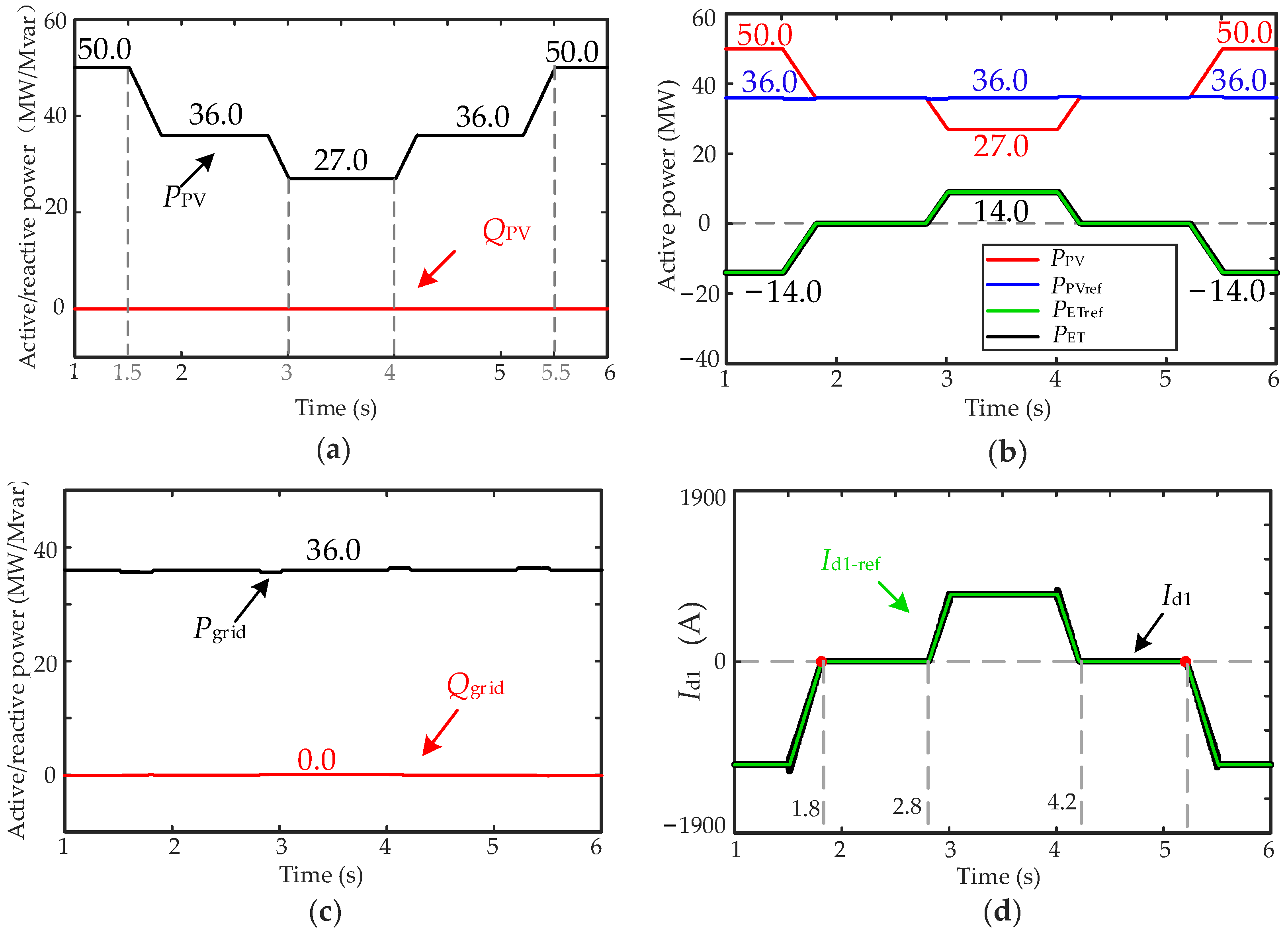
When the bypass switch S is closed, E-UPFC works in power suppression mode. In this paper, the rated capacity of PV power generation system is set as 50 MW. When t = 1.5 s~5.5 s, the output power of the PV power generation system simulates intermittent fluctuations. At 1.5 s, the output power of PV system gradually decreases from 50 MW to 27 MW, and then gradually increases to 50 MW, as shown in Figure 12a. At the same time, it is assumed that the reference value of the PV grid-connected power is 36 MW.
Figure 12b shows the actual power output of the PV power generation system and E-UPFC. As the output power of the PV grid-connected system begins to fluctuate within 0.5 s, E-UPFC dynamically compensates according to the calculated compensation power reference value, so as to ensure that the PV power generation system transmits constant power to the grid. Figure 12c shows that between 1.5 s and 5.5 s, the exchange power between the PV power generation system and the grid is a constant value of 36 MW, which means that the PV power fluctuation has no impact on the generation load balance of the transmission network.
Figure 12d shows the output current of FE-MMC of E-UPFC. At 0~2.2 s, when the output power PW of the PV grid-connected system is greater than the reference value of the PV grid-connected power Po, the inductance current Id1 flows from the grid side to the DC side, and the ESS absorbs power and gradually decreases. At 2.2 s, when the current Id1 is 0, the ESS neither absorbs nor releases power. When PPV is less than Po after 2.2 s, the current Id1 flows from the DC side to the grid, and the ESS releases power. Similarly, after 4.09 s, the ESS absorbs and releases power according to Equation (1). Therefore, the ESS of E-UPFC can suppress the power fluctuation caused by the PV grid-connected system and ensure the stable operation of the transmission network.

5.2. Power Regulation Mode

It has been verified that T can suppress power fluctuations in the PV power generation system at the grid-connected node in Section 5.1. At the same time, the power flow regulation ability of E-UPFC on the transmission network is verified in this section. When the bypass switch S is disconnected, the BE-MMC in E-UPFC can be connected to Line 1 on the transmission network through the series winding of transformer T.
According to the diagram of the IEEE 3-generator 9-bus system in Figure 11, the following simulation verification of E-UPFC for power flow regulation is carried out. It is assumed that the load power (PL + jQL = 125 + j50MVA) at bus 5 remains unchanged and the ratio of active and reactive power on line 1 and line 5 is constantly changed by E-UPFC. The simulation can be divided into the following three working conditions:
(a)
Condition 1: line power P1: P2 = 2:3, Q1: Q2 = 2: 3.
(b)
Condition 2: line power P1: P2 = 1:1, Q1: Q2 = 1: 1.
(c)
Condition 3: line power P1: P2 = 3:2, Q1: Q2 = 3: 2.
Figure 13 shows the simulation waveforms of the power on line 1 and line 2 regulated by E-UPFC. When the ratio of line 1 power P1 + jQ1 and line 2 power P2 + jQ2 is changed by E-UPFC, it can be seen that active power and reactive power on the two lines change with the output voltage of BE-MMC. The simulation values of E-UPFC power flow regulation under the three working conditions are given in Table 1. It can be seen from Figure 13 and Table 1 that E-UPFC can effectively regulate the power flow on the line, and it is verified that E-UPFC has high regulation accuracy.
According to the diagram of the IEEE 3-generator 9-bus system in Figure 11, it is assumed that the power of line 1 is set at the constant value PL + jQL = 125 + j50MVA, and the simulation can be divided into the following three working conditions:
(a)
Condition 1: PL + jQL = 125 + j50 MVA.
(b)
Condition 2: PL + jQL = 100 + j30 MVA.
(c)
Condition 3: PL + jQL = 160 + j65 MVA.
Figure 14 shows the simulation waveforms of the power flow regulation under load power change by E-UPFC. And the simulation values of E-UPFC power flow regulation under load power change are given in Table 2. Therefore, it can be seen from Figure 14 and Table 2 that when the load power PL + jQL at bus 5 changes, the power P1 + jQ1 on line 1 can remain unchanged under the regulation of E-UPFC, while the power P2 + jQ2 on line 2 changes due to load changes. At the same time, when the load increases or decreases suddenly, E-UPFC can control the output voltage of BE-MMC to adjust in time, and can control the current of line 1 to remain almost unchanged, that is, the power P1 + jQ1 on line 1 is always kept in a stable range.

6. Conclusions

This article proposes an E-UPFC installed at the renewable energy grid connection node of the transmission network, which can suppress the power fluctuations of grid-connected node injected by large-scale renewable energy and regulate the power flow on its connected transmission lines. In the above sections, the principle of power flow regulation and the topology and control strategies of E-UPFC are illustrated. The simulation results in power suppression mode and power regulation mode validate the correctness of the proposed E-UPFC. And the proposed E-UPFC has the following advantages.
  • Through the buffering effect of ESS, the proposed E-UPFC can suppress the power fluctuations of large-scale renewable energy at the grid-connected node so as to ensure the friendly and smooth integration of renewable energy into the power grid;
  • By transferring the installation position of E-UPFC from the transmission line to the node, the power transformer can be better protected, so as to extend the service life of the power transformer;
  • The proposed E-UPFC can dynamically control the amplitude and phase of the output voltage and realize the decoupling control of the active power and reactive power of the transmission lines, so as to improve the dynamic regulation ability of the power flow of the transmission network.

Author Contributions

The authors confirm their contribution to the paper as follows: W.Y.: conceptualization, methodology, simulation, experiment, drawing, data processing, writing—original draft, writing—review and editing; C.L.: communication, resources; L.Y.: experimental support. All authors have read and agreed to the published version of the manuscript.

Funding

This research was funded by China State Grid Jilin Electric Power Co., Ltd. Siping Power Supply Company (No. SGJLSP00XTJS2301441) “Research on Key Technologies of hybrid solid state intelligent distribution transformer to enhance the capability of carrying distributed generation”.

Data Availability Statement

Data are contained within the article.

Conflicts of Interest

Author Cong Liu was employed by the company Siping Power Supply Company. The remaining authors declare that the research was conducted in the absence of any commercial or financial relationships that could be construed as a potential conflict of interest. The authors declare that this study received funding from State Grid Corporation of China. The funder was not involved in the study design, collection, analysis, interpretation of data, the writing of this article or the decision to submit it for publication.

References

  1. De Araujo, R.A.; Torres, S.P.; Pissolato Filho, J.; Castro, C.A.; Van Hertem, D. Unified AC transmission expansion planning formulation incorporating VSC-MTDC, FACTS devices, and reactive power compensation. Electr. Power Syst. Res. 2023, 216, 109017. [Google Scholar] [CrossRef]
  2. You, L.; Ma, H.; Saha, T.K. A CVaR-constrained optimal power flow model for wind integrated power systems considering Transmission-side flexibility. Int. J. Electr. Power Energy Syst. 2023, 150, 109087. [Google Scholar] [CrossRef]
  3. Khaleel, M.; Yusupov, Z.; Yasser, N.; Elkhozondar, H.; Ahmed, A.A. An integrated PV farm to the unified power flow controller for electrical power system stability. Int. J. Electr. Eng. Sustain. (IJEES) 2023, 1, 18–30. [Google Scholar]
  4. Shair, J.; Li, H.; Hu, J.; Xie, X. Power system stability issues, classifications and research prospects in the context of high-penetration of renewables and power electronics. Renew. Sustain. Energy Rev. 2021, 145, 111111. [Google Scholar] [CrossRef]
  5. Amrr, S.M.; Asghar, M.J.; Ashraf, I.; Meraj, M. A comprehensive review of power flow controllers in interconnected power system networks. IEEE Access 2020, 8, 18036–18063. [Google Scholar]
  6. Mosaad, M.I.; Alenany, A.; Abu-Siada, A. Enhancing the performance of wind energy conversion systems using unified power flow controller. IET Gener. Transm. Distrib. 2020, 14, 1922–1929. [Google Scholar] [CrossRef]
  7. Seifi, A.; Gholami, S.; Shabanpour, A. Power flow study and comparison of FACTS: Series (SSSC), Shunt (STATCOM), and Shunt-Series (UPFC). Pac. J. Sci. Technol. 2010, 11, 129–137. [Google Scholar]
  8. Kotsampopoulos, P.; Georgilakis, P.; Lagos, D.T.; Kleftakis, V.; Hatziargyriou, N. Facts providing grid services: Applications and testing. Energies 2019, 12, 2554. [Google Scholar] [CrossRef]
  9. Elmetwaly, A.H.; Eldesouky, A.A.; Sallam, A.A. An adaptive D-FACTS for power quality enhancement in an isolated microgrid. IEEE Access 2020, 8, 57923–57942. [Google Scholar] [CrossRef]
  10. Alvaro, R.; Águila Téllez, A.; Ortiz, L. Optimal Location and Sizing of a D-STATCOM in Electrical Distribution Systems to Improve the Voltage Profile Considering the Restriction of Harmonic Injection through the JAYA Algorithm. Energies 2023, 16, 7683. [Google Scholar] [CrossRef]
  11. Gao, C.; Liu, H.; Jiang, H.; Li, Y.; Tang, X. Research on the sub-synchronous oscillation in wind power connected to series compensated power system and its influencing factors. CES Trans. Electr. Mach. Syst. 2017, 1, 334–340. [Google Scholar] [CrossRef]
  12. Bocovich, M.; Iyer, K.; Terhaar, R.M.; Mohan, N. Overview of series connected flexible AC transmission systems (FACTS). In Proceedings of the 2013 North American Power Symposium (NAPS), Manhattan, KS, USA, 22–24 September 2013; IEEE: Piscataway, NJ, USA, 2013; pp. 1–6. [Google Scholar]
  13. Kannan, S.; Jayaram, S.; Salama, M.M.A. Real and reactive power coordination for a unified power flow controller. IEEE Trans. Power Syst. 2004, 19, 1454–1461. [Google Scholar] [CrossRef]
  14. Ke, S.; Zhu, M.; Chen, Y.; Zheng, C.; Hu, C. Passive Sliding Mode Variable Structure Control For MMC-UPFC. In Proceedings of the 2019 IEEE Innovative Smart Grid Technologies—Asia (ISGT Asia), Chengdu, China, 21–24 May 2019; IEEE: Piscataway, NJ, USA, 2019; pp. 2184–2189. [Google Scholar]
  15. Zhu, P.; Liu, L.; Liu, X.; Kang, Y.; Chen, J. Performance of a decoupling control scheme for a unified power flow controller. In Proceedings of the 31st Annual Conference of IEEE Industrial Electronics Society, 2005 (IECON 2005), Raleigh, NC, USA, 6–10 November 2005; IEEE: Piscataway, NJ, USA, 2005; pp. 6–12. [Google Scholar]
  16. Bidadfar, A.; Abedi, M.; Karari, M.; Chu, C. Power swings damping improvement by control of UPFC and SMES based on direct Lyapunov method application. In Proceedings of the 2008 IEEE Power and Energy Society General Meeting-Conversion and Delivery of Electrical Energy in the 21st Century, Pittsburgh, PA, USA, 20–24 July 2008; IEEE: Piscataway, NJ, USA, 2008; pp. 1–7. [Google Scholar]
  17. Kazemi, A.; Esmaielie, A.; Hassanzade, M.T.; Rezaiepour, R. A comprehensive load flow model for UPFC and its combination with ESS. In Proceedings of the International Conference on Electrical and Electronics Engineering ELECO-2008, Bursa, Turkey, 26–30 November 2008; IEEE: Piscataway, NJ, USA, 2008. [Google Scholar]
  18. Zhang, L.; Shen, C.; Crow, M.L.; Atcitty, S. A comparison of FACTS integrated with battery energy storage systems. In Proceedings of the 2001 IEEE/PES Transmission and Distribution Conference and Exposition, Atlanta, GA, USA, 2 November 2001; IEEE: Piscataway, NJ, USA, 2008; pp. 1151–1155. [Google Scholar]
  19. Kandasamy, S.; Rajapalan, A. Dynamic control modeling and simulation of a UPFC–SMES compensator in power systems. Ain Shams Eng. J. 2015, 6, 1179–1186. [Google Scholar] [CrossRef]
  20. Merritt, N.R.; Chakraborty, C.; Bajpai, P. An E-STATCOM Based Solution for Smoothing Photovoltaic and Wind Power Fluctuations in a Microgrid Under Unbalanced Conditions. IEEE Trans. Power Syst. 2022, 37, 1482–1494. [Google Scholar] [CrossRef]
  21. Osama abed el-Raouf, M.; Mageed, S.A.A.; Salama, M.M.; Mosaad, M.I.; AbdelHadi, H.A. Performance Enhancement of Grid-Connected Renewable Energy Systems Using UPFC. Energies 2023, 16, 4362. [Google Scholar] [CrossRef]
  22. Xu, Y.; Zhang, Z.; Wang, G.; Xu, Z. Modular Multilevel Converter with Embedded Energy Storage for Bidirectional Fault Isolation. IEEE Trans. Power Deliv. 2022, 37, 105–115. [Google Scholar] [CrossRef]
  23. Guan, M.; Xu, Z. Modeling and Control of a Modular Multilevel Converter-Based HVDC System Under Unbalanced Grid Conditions. IEEE Trans. Power Electron. 2012, 27, 4858–4867. [Google Scholar] [CrossRef]
  24. Huangfu, Y.; Li, Q.; Xu, L.; Ma, R.; Gao, F. Extended State Observer Based Flatness Control for Fuel Cell Output Series Interleaved Boost Converter. IEEE Trans. Ind. Appl. 2019, 55, 6427–6437. [Google Scholar] [CrossRef]
  25. Zhao, B.; Song, Q.; Li, J.; Sun, Q.; Liu, W. Full-Process Operation, Control, and Experiments of Modular High-Frequency-Link DC Transformer Based on Dual Active Bridge for Flexible MVDC Distribution: A Practical Tutorial. IEEE Trans. Power Electron. 2017, 32, 6751–6766. [Google Scholar] [CrossRef]
  26. Zhang, H.; Li, Y.; Li, Z.; Zhao, C.; Gao, F.; Xu, F.; Wang, P. Extended-State-Observer Based Model Predictive Control of a Hybrid Modular DC Transformer. IEEE Trans. Ind. Electron. 2022, 69, 1561–1572. [Google Scholar] [CrossRef]
Figure 1. The schematic diagram of PV grid-connected system with UPFC.
Energies 17 01411 g001
Figure 2. The schematic diagram of PV grid-connected system with E-UPFC.
Energies 17 01411 g002
Figure 3. The schematic diagram of power flow regulation by BE-MMC in E-UPFC.
Energies 17 01411 g003
Figure 4. The topology diagram of MMC and its HB submodule.
Energies 17 01411 g004
Figure 5. The average models of equivalent circuits of MMC: (a) equivalent circuit on AC side; (b) equivalent circuit on DC side.
Energies 17 01411 g005
Figure 6. The topology of the DCT.
Energies 17 01411 g006
Figure 7. The equivalent average-value model of DCT.
Energies 17 01411 g007
Figure 8. The control strategy of FE-MMC.
Energies 17 01411 g008
Figure 9. The control strategy of BE-MMC.
Energies 17 01411 g009
Figure 10. The control strategy of DCT.
Energies 17 01411 g010
Figure 11. The diagram of the IEEE 3-generator 9-bus system with E-UPFC.
Energies 17 01411 g011
Figure 12. The simulation waveform of E-UPFC working in power suppression mode: (a) the output power of PV power generation system with intermittent fluctuation components; (b) the actual power output of the PV power generation system and E-UPFC; (c) the actual grid-connected power; (d) the output current of FE-MMC of E-UPFC. The red dot represents the turning point of the FEC-MMC output current.
Energies 17 01411 g012
Figure 13. The simulation waveforms of the power on line 1 and line 2 regulated by E-UPFC. (a) Variation diagram of parallel line current and BE-MMC of E-UPFC output voltage. (b) Active power variation diagram of line 1 and line 2. (c) Reactive power variation diagram of Line 1 and Line 2.
Energies 17 01411 g013
Figure 14. The simulation waveforms of the power flow regulation under load power change by E-UPFC. (a) Variation diagram of parallel line current and BE-MMC of E-UPFC output voltage. (b) Variation diagram of active power and reactive power of Line 1. (c) Variation diagram of active power and reactive power of Line 2.
Energies 17 01411 g014
Table 1. The simulation values of E-UPFC power flow regulation under the three working conditions of power ratio change.
ConditionPL + jQL/MVAP1 + jQ1/MVAP2 + jQ2/MVA
1125 + j5050 + j2075 + j30
2125 + j5062.5 + j2562.5 + j25
3125 + j5075 + j3050 + j20
Table 2. The simulation values of E-UPFC power flow regulation under load power change.
ConditionPL + jQL/MVAP1 + jQ1/MVAP2 + jQ2/MVA
1125 + j5050 + j2075 + j30
2110 + j4050 + j2060 + j20
3150 + j6550 + j20100 + j45
Disclaimer/Publisher’s Note: The statements, opinions and data contained in all publications are solely those of the individual author(s) and contributor(s) and not of MDPI and/or the editor(s). MDPI and/or the editor(s) disclaim responsibility for any injury to people or property resulting from any ideas, methods, instructions or products referred to in the content.