Article

A Compound Control Strategy for an Ultralight Power Generation System

1
Institute of Electrical Engineering, Chinese Academy of Sciences, Beijing 100190, China
2
University of Chinese Academy of Sciences, Beijing 100049, China
*
Author to whom correspondence should be addressed.
Energies 2024, 17(6), 1402; https://doi.org/10.3390/en17061402
Submission received: 5 February 2024 / Revised: 26 February 2024 / Accepted: 27 February 2024 / Published: 14 March 2024
(This article belongs to the Section F: Electrical Engineering)

Abstract

:
Ultralight power generation equipment has high requirements for the power density, continuous operation, and transient stability of the whole machine, and there is a direct conflict between high power density and substantial stability control in the power unit design. In order to meet the power density requirements of ultralight power stations, three main problems need to be solved, namely engine speed oscillation and flameout in the process of load power mutation, matching of the generator and engine torque, and stabilizing the voltage waveform of the AC output end. In this paper, we proposed an exquisite compound control strategy for ultralight power generation systems in engines, generators, and inverters. The effectiveness and practicability of the proposed strategy are verified by both simulation and experiment. The results show that the proposed control strategy can effectively solve the instability problem of the ultralight generator set and improve the stability of the system, where response recovery can be achieved within 0.9 s under the conditions of a total load increase or decrease, and the mismatching degree of the generator following the engine is reduced by 90%. The strategy could also guarantee long-term stable operation with high-quality electrical energy output.

1. Introduction

Ultralight power generation equipment and systems have many similarities and differences compared with aviation power generation systems, marine integrated power systems, and electric vehicle power systems. One or more prime movers provide several power generation scenarios. According to the topology of the power generation system, the generator output power can be subdivided into series type, parallel type, and hybrid type; according to the source of energy, it can be divided into all-electric and hybrid types. The single power and weight of ultralight mobile power generation equipment is minimal (usually not more than 1 kW, 10 kg), and the speed is relatively high (rated speed is not less than 6500 rpm), which is different from the two-stroke aero-engine and megawatt high-power diesel engine in the power system of electric transmission vehicles. This kind of ultralight power generation equipment system is suitable for micro-displacement four-stroke gasoline engines, which have specific compact requirements, and higher speed can reduce the size and weight burden of generator design. In light mobile power generation equipment, the generator in the power unit usually uses a permanent magnet generator. Due to the size and efficiency limitations, it is difficult to use the generator with electric excitation or compound excitation, which also increases the difficulty of the internal speed regulation and control of the power unit. In addition, ultralight mobile power generation equipment has different system characteristics and requirements, such as no energy storage unit, lightweight, high speed, low power and small inertia, scalability, and other application characteristics. It should be noted that to ensure the reliability of use, the ultralight power generation equipment system does not contain lithium batteries, supercapacitors, or other energy storage modules.
The speed regulation of the power generation unit (composed of an engine and a generator) relies on the engine to control the speed, and the generator regulates the electromagnetic torque (engine load torque) through the rear rectifier unit and then controls the output power of the unit [1,2,3,4,5,6]. This method can make the unit respond quickly to the load power demand and is widely used in general power plants, hybrid vehicle systems, and marine integrated power systems [7]. The generator sets in these power environments do not require frequent speed regulation, and the prime mover can be selected with sufficiently large specifications [8]. The researchers found the following information regarding the generator sets that make up the vehicle’s integrated power system. On the one hand, due to the efficiency of the installed capacity in the car, the power of the engine and the generator is roughly similar when the vehicle needs high-speed bending or rapid acceleration, the sudden increase in the load power of the vehicle may make the electromagnetic torque of the generator as a resistance moment exceed the engine output torque in a short time, and the connecting shaft of the power generation unit is mainly affected by the generator, resulting in the instability of the unit. On the other hand, due to the coupling relationship between the output capacity of the unit and the fuel economy and the speed, the unit needs to switch to different target speed points frequently according to the driving demand [9,10,11,12]. In response to the above problems, scholars have proposed control strategies, such as constant speed QFT (Quantitative Feedback Theory) robust control, fuzzy control, and sliding mode control [13,14,15,16]. However, due to the characteristics of the ultralight power station system, such as small inertia, small capacity, high speed rating of the power generation unit, and unbuffered energy storage unit, the above strategies are not applicable. Therefore, it is necessary to design a speed stability control strategy that allows its power generation unit to maintain lasting and stable operation under different working conditions and switching conditions.
The series hybrid power system has the advantages of a simple structure and relatively simple optimization control. No mechanical connection can be set between the engine and the transmission, and the engine speed and torque can be adjusted to make it work in the maximum efficiency zone. In recent years, the problem of coordination control of engine-generator sets used in many independent power systems’ primary power sources at home and abroad has become increasingly prominent [13]. During the running of hybrid electric vehicles, the engine needs to switch the speed operating point according to the optimal fuel economy consumption following the control strategy. However, an excessive loading rate will limit the speed adjustment ability of the engine generator set. Currently, the actual speed can no longer track the target speed, and the required power of the rear power chain exceeds the output capacity of the engine generator set. Because of this problem, the literature [17] studies the influence of different loading rates on the engine speed-switching process. It gives the maximum allowable loading rates at different speeds through simulation to avoid engine overload. Wen Boxuan et al. [7] improved the speed adjustment ability by setting the transmission device between the engine and the generator. However, the limiting loading rate is too low. In this case, it will slow down the power response ability of the unit, and if the limiting loading rate is too large, it is difficult to avoid the oscillation of the unit speed. Obtaining the optimal limiting amplitude of the loading rate takes work. Because of the cancellation of the mechanical connection between the unit and the motor, the generator is generally dragged directly by the engine, and increasing the transmission device is more suitable for parallel and hybrid systems. In short, there is little research on this problem and no unified solution. In the dynamic regulation of the unit, the internal problem of the engine–generator set system is mainly speed adjustment [18], and the external problem is mainly the electric power response output to the bus [19,20,21]. Based on these two problems, this paper adopts the speed regulation method of the engine throttle opening to adjust the output power and the generator controller to adjust the speed to control the changes of electromagnetic torque reasonably and avoid the situation of engine overload or even car failure during the dynamic regulation process. At the same time, the adjustment time and the minimum energy loss of the whole process are optimized, and the high-quality power supply to the DC bus is realized by rationally configuring the electromagnetic torque variation interval of the generator. Through the hardware-in-the-loop simulation of a series-connected vehicle-mounted integrated power system, the reliability of the proposed control strategy is verified.
Because of its simple structure and flexible layout, a series power generation system has become one of the typical schemes of power generation equipment. The engine–generator set is used for external power supply. However, because the stability of a single chain structure could be more substantial, a reasonable design is needed to achieve coordinated and efficient work of the system [2,3,4,5]. When the load power is suddenly increased, or the system is subject to long-term high-power operation and other extreme conditions, the following characteristics of the power supply system are required. Especially in the rapid acceleration process, the dynamic change of load power is excellent, so it is urgent to research power balance control strategies. A gasoline engine has the characteristics of nonlinear and multi-operating conditions, and these dynamic characteristics change with changes in speed and load. At present, some scholars have studied the control of gasoline engines. In the literature [2,3], sliding mode control and synthesis methods were used to study the speed control of automobile gasoline engines. In contrast, in the literature [4,5], QFT robust control and dynamic output feedback control systems were used to study the constant speed control of small unmanned helicopter engines. In the above control methods, most of the engine system is regarded as a single class of an uncertain or parameter perturbation system, without considering the different dynamic performances of the engine under different working conditions, and the dynamic performance of the system is not improved from the angle of load disturbance feedforward compensation.
This paper analyzes the working mechanism of a small gasoline generator. It is concluded that the main factor that destroys the steady state of the system is the sudden change in the system load. Therefore, a feedforward multimodal feedback control algorithm is proposed, combining feedforward control, traditional PID (Proportional Integral and Differential), and fuzzy control. This method uses fuzzy control when the operating condition changes, linear PID control when the system is steady, and feedforward compensation to suppress the load disturbance. The simulation and test results show that this method effectively improves the steady-state and dynamic performance of small gasoline generators.
Section 2 mainly introduces the modeling and control strategy of the generator, Section 3 introduces the modeling and control strategy of the generator, Section 4 introduces the modeling and control strategy of the inverter. Finally, the experimental part and the verification of control strategy are introduced.

2. Engine Control Strategy Design

The engine control strategy discussed in this section is mainly aimed at the problem of speed oscillation caused by a load sudden change during stable operation. By controlling the stability of engine speed, the stability coefficient of the power generation system is guaranteed.

2.1. Engine Instability Principle and Control Task Analysis

Considering the instability of the power unit due to sudden load change, it can be concluded that the instability of power unit speed control can be divided into three types:
(1)
Shaft speed oscillation and shutdown caused by a sudden load;
(2)
Speed and shutdown caused by a sudden load reduction;
(3)
Vibration of the shaft speed and fracture of connecting the shaft between the engine and generator caused by a minor disturbance during high-speed operation and stable conditions are shown in Figure 1, separately.
The associated instability caused by an abnormal start and stop is not considered here.
The influence of a sudden change in load before instability on each part and parameter of the power unit is discussed, as shown in Figure 2. It can be seen that the influence of load on the power unit proceeds from the rear stage to the forward stage and is related to the inertia of each component.
The closed-loop feedback control model of power unit speed is shown in Figure 3. As can be seen from the control block diagram of the power unit, in the process of power flow, the regulation of the speed of the power unit by the generator is opposite to that caused by the power change. That is, when the load is suddenly applied (the target output power increases), the speed tends to decrease due to the inertia sag characteristic. However, increasing the output power after the feedback of the power unit is a process generated by speed, causing a contradiction in speed control because the speed should be reduced when the output power of the power unit is reduced. Therefore, when the generator’s regulating effect on the speed is stronger than the engine’s regulating effect on the speed, the speed oscillates, which explains the instability of the speed feedback control after the above load’s sudden change and disturbance. The following Table 1 and Table 2 lists the parameters of the speed feedback control system.
The instability problem is further quantitatively analyzed, and the carburetor (throttle) opening, engine output torque, and engine output shaft speed are considered system variables (x1, x2, x3). According to the control relationship in Figure 3, the steady-state operating point is translated to the origin of coordinates through coordinate transformation, and the expression can be obtained as follows:
ω x 3 k p s + k i s = x 1 + Δ x 1 K x 1 + Δ x 1 x 3 + ω 0 1 T D E n g s + 1 = x 2 + Δ x 2 x 2 + Δ x 2 P o x 3 + ω 0 = x 3 + Δ x 3
According to Lyapunov indirect method, the Jacobian matrix of the system near the steady-state operating point can be obtained as follows:
A = 0 k p J k p J k i P k p J ω 0 2 K ω 0 T D E n g 1 T D E n g K η T D E n g 0 1 J P J ω 0 2
A set of Eigen roots (0, −2.5000, −1.0882) in a steady state is calculated. We can know that the system is in a state that is easy to lose stability control.

2.2. Design of the Engine Current Feedforward Control Strategy

PID control is generally adopted for a single-speed feedback loop, but it cannot meet engine control requirements in an ultralight power generation system. Due to the contradiction between the control period and response time caused by the small inertia and high engine speed, it is necessary to consider adding feedforward links to improve response speed. Here, the compound control strategy of speed feedback combined with load current feedforward is adopted. The overall control block diagram is shown below.
The platform experiment shows that the current feedforward strategy can reduce the speed fluctuation time caused by the load change. IN the control loop, the relation between feedforward controller output and load current change IN(n) can be expressed as follows:
u f ( n ) = f ( I N ( n ) )
The output control quantity of incremental PID control in the figure above is described as follows:
Δ u ( n ) = k P [ e ( n ) e ( n 1 ) ] + k I e ( n ) T
where T is the sampling period.
The system control structure of the load current feedforward compound speed feedback loop is shown in Figure 4. The principle of composite control is described as follows. When the load changes, the load current is input to the feedforward controller, and the speed compensation signal is output to the controller to produce real-time compensation without difference. The influence of disturbance on the controlled quantity is eliminated in time. The compound feedback controller can guarantee the system control effect.
The functional relation of key process variation caused by a load sudden change is established, and the load power-carburetor opening relation and sudden change in load amount-carburetor opening change value are stored. The control cycle time is optimized to improve the control efficiency.

3. Generator Control Strategy Design

The generator control strategy is also aimed at the torque mismatch between the engine and the generator caused by the sudden change of the load in the power generation system. The torque of the engine and the generator is not equal. This will be reflected in their connecting shaft and then cause the problem of the post-stage unit. By controlling the rectifier connected to the generator, the electromagnetic torque of the generator can be adjusted, so that the electromagnetic torque of the generator tracks the torque of the engine, ensuring that there is no torque difference between the two. Thus, the stability of the power generation system is improved.

3.1. Analysis of the Equivalent Model of the Generator and PWM Rectifier

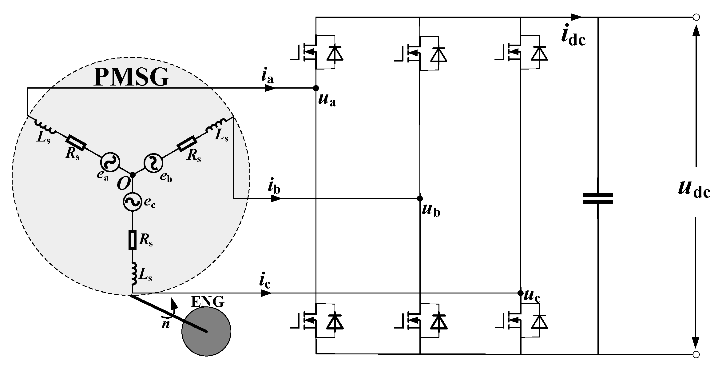
In Figure 5, the dotted line frame is the alternator-rectifier equivalent circuit, where ea, eb, and ec are the equivalent electromotive forces of the three-phase winding; Rs is the equivalent resistance of armature winding and filter inductance; Ls is the sum of equivalent armature inductance, drain inductance and filter inductance; and Co is the filter capacitor on the DC side.
PMSG-VSR voltage/current equation (three-phase coordinate system):
e a = R s i a L s d i a d t + S a U d c S a + S b + S c 3 e b = R s i b L s d i b d t + S b U d c S a + S b + S c 3 e c = R s i c L s d i c d t + S c U d c S a + S b + S c 3 C d U d c d t = S a i a + S b i b + S c i c i L o a d
Rotation transformation: ea-eb-eced-eq, ia-ib-icid-iq, Sa-Sb-ScSd-Sq, LsLd-Lq.
PMSG-VSR voltage/current equation (dq coordinate system): ωLdiq, ωψf-ωLdid.
e d = R s i d L s d i d d t + ω L q i q + S d U d c e q = R s i q L s d i q d t ω L d i d + ω φ f + S q U d c C d U d c d t = 3 2 ( S d i d + S q i q ) i L o a d
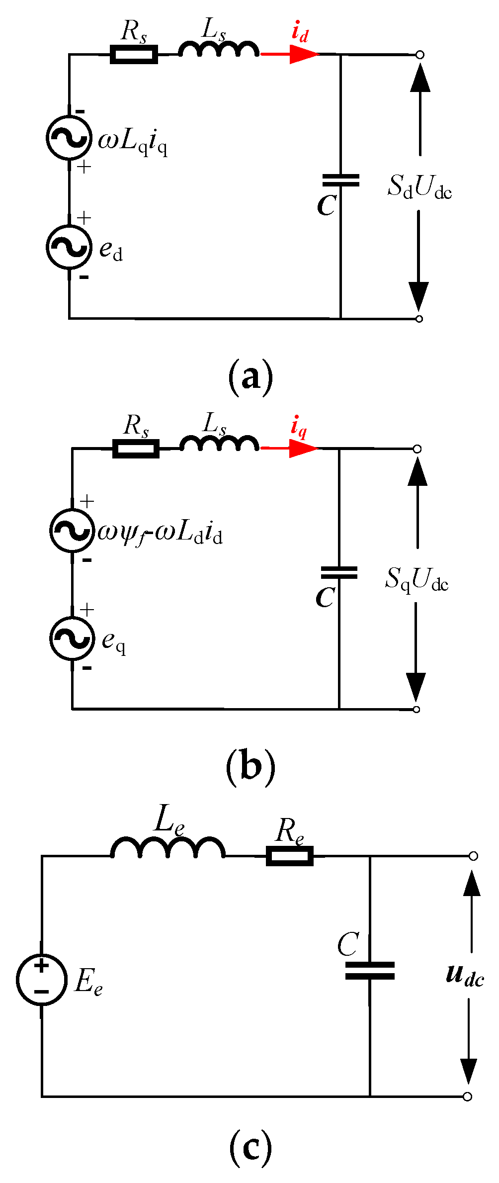
The PMSG-VSR d-q equivalent diagram and original coordinate equivalent diagram are presented in Figure 6.
To sum up, the circuit equivalent diagram of the three-phase permanent magnet synchronous motor and rectifier in dq coordinate system is shown in Figure 6, including back electromotive force, induced electromotive force, and DC bus voltage.

3.2. Instability Analysis of Generator and Engine

On the other hand, due to the coupling relationship between the output capacity of the unit and the fuel economy and the speed, the unit needs to change the speed point frequently according to the driving demand. In order to deal with the contradiction between the power following control and the speed regulation of the unit, it is necessary to analyze the cause of the instability of the unit first.
The speed regulation relationship of the generator set is expressed as follows:
T E n g T e = J d ω d t
where T is the dynamic torque output by the engine; Te is the electromagnetic torque of the generator; J is the moment of inertia of the unit shaft; and ω is the axial angular velocity. The engine self-stability coefficient S is introduced from the speed regulation relation as follows:
S = T E n g ω T e ω
S = Δ T E n g Δ ω Δ T e Δ ω = ( Δ T E n g Δ T e ) Δ ω
The load torque of the engine is the electromagnetic torque of the generator. The larger the S value is, the stronger the ability of the engine to return to the steady state during the adjustment of the engine speed is. The smaller the S value, the weaker the ability to return to steady state. However, when the load changes too fast and S < 0, the electromagnetic torque as the resistance moment exceeds the dynamic torque output by the engine, the unit is unstable, and coordination and matching control is needed.

3.3. Generator Electromagnetic Torque following Strategy Design

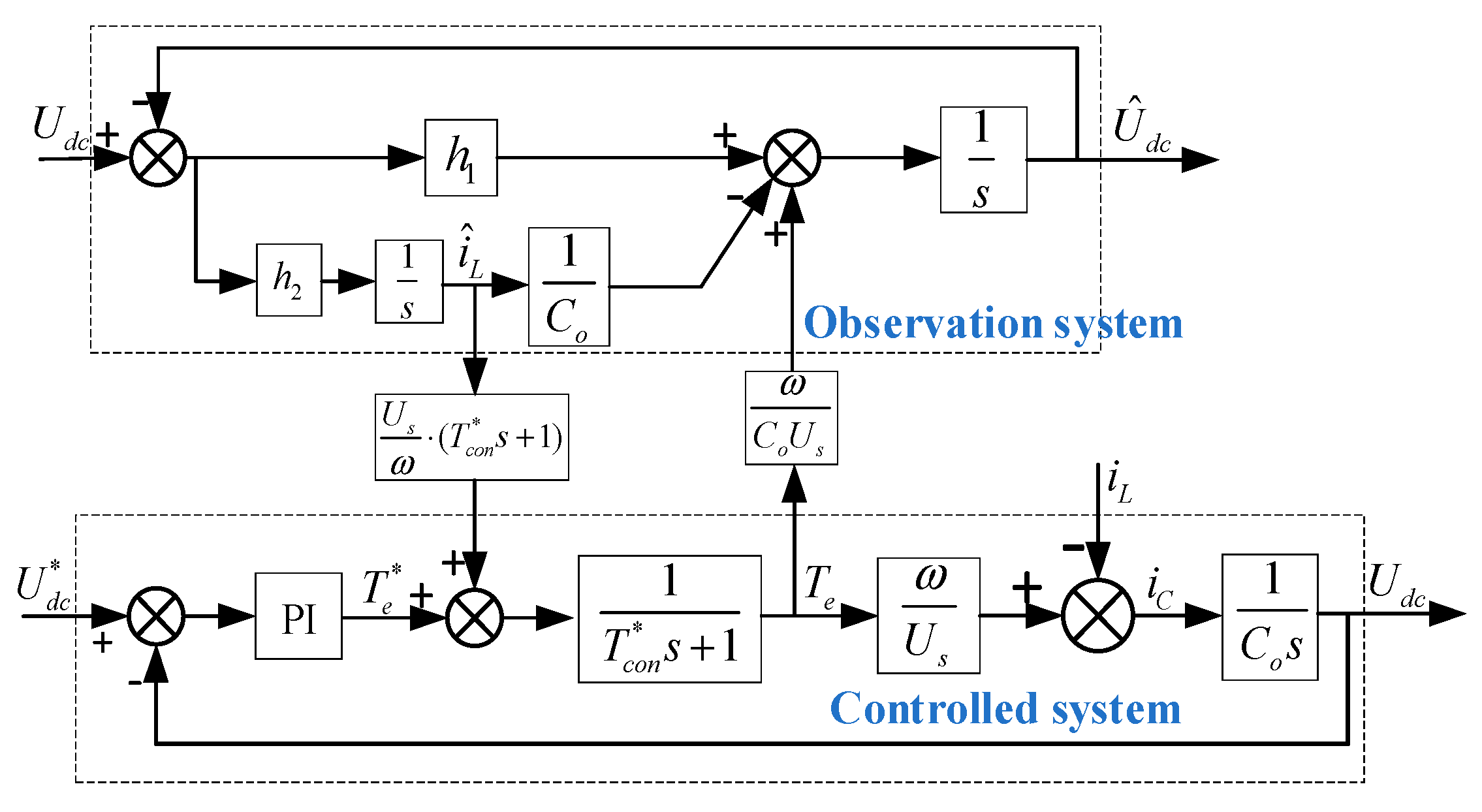
In view of the influence of disturbance factors, such as load torque and motor parameter change, on the system control performance, a load torque observer is designed to observe the load torque, and the real-time observed torque value is converted into load current and introduced into the input end of the current regulator as a feedforward compensation link to compensate the output of the new speed controller. It can be seen that after the load torque feedforward compensation is added, the q axis torque reference current consists of two parts: the output current component of the new speed controller and the torque compensation current component. The change of load torque will directly cause the change of torque compensation current, so that the torque current corresponding to the equivalent load torque can be generated as soon as possible when the load torque changes or is disturbed. Therefore, the anti-load disturbance ability of the system is improved. Observer principle and application design are shown in Figure 7.
By setting the poles of the observer reasonably, the output of the observer can track the real state of the system. After realizing the disturbance observation, the disturbance output of the observer needs to be provided to the PID controller as compensation to offset the disturbance brought by the real disturbance to the displacement ring. The optimized anti-disturbance control block diagram is shown in Figure 8.
Based on the above analysis, the control principle block diagram of the new speed controller of the direct-drive permanent magnet synchronous motor based on load torque observer is obtained, as shown in Figure 9.

4. Inverter Control Strategy Design

The inverter control strategy in this section is mainly aimed at the load response capability and accuracy of the inverter during operation because the load mutation will affect the output capability of the inverter. In addition, the AC output quality and capability of the power generation system can be improved through the control strategy.

4.1. Inverter Topology and Working Principle Analysis

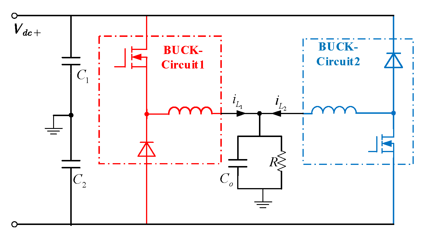
A dual buck inverter consists of two sets of identically symmetrical buck circuits, as shown in Figure 10. ud is the input power supply; UC is the filter capacitor voltage; iL1 and iL2 are the currents of the filter inductor L1 and L2, respectively; io is the load current; and Co, L1, and L2 constitute the low-pass filter. S1 and S2 are two complementary switching tubes, D1 and D2 are two complementary diodes, and Cf is the filter capacitor. When Uo is positive, S1 and D1 modulation work, whereas S2 and D2 are cut off. When Uo is negative, S2 and D2 modulation work, and S1 and D1 are cut off. Because of the existence of power devices, the inverter is essentially a nonlinear system. Assuming that the input voltage is constant, the power tube is an ideal device, and the switching frequency is much higher than the output fundamental frequency of the inverter and the resonant frequency of the LC filter, the approximate model of the inverter can be simplified as shown in Figure 11.
As can be seen from Figure 11 and Figure 12, one buck circuit in the single-phase half-bridge double-buck inverter can provide forward sinusoidal current, and the other buck circuit can provide negative sinusoidal current, and the output current is in the form of sinusoidal current superimposed by the output current of the two circuits.
Voltage ud is a voltage pulse sequence with amplitude ±ud, L = L1 = L2. Taking inductance current iL and capacitance voltage uC as state variables, the equation of the small signal state of double Buck inverters is noted as follows:
i ˙ L u ˙ C = 1 L u d 1 L u C 1 C i L 1 R C u C
The inverter small signal equation is written as a standard mode (distinguish state quantity and control quantity) as follows:
d i ^ L ( t ) d t d u ^ C ( t ) d t = 0 1 L 1 C 1 R C i ^ L ( t ) u ^ C ( t ) + 1 L 0 u ^ d ( t )
According to the small signal equation of state, the transfer function between inductance current and control quantity (PWM) is obtained (small signal premise):
G 1 ( s ) = i L ( s ) u d _ p w m ( s ) = R C s + 1 R L C s 2 + L s + R
The above formula is derived from the load current relationship.
If the filter capacitor equivalent series resistance is considered, the main power loop open-loop transfer function can be written as follows:
G v d ( s ) = U d 1 + s ω e s r 1 + s ω 0 Q + ( s ω 0 ) 2 = U d 1 + C r e s r s L C s 2 + L R s + 1
If the equivalent series resistance is not considered,
u C ( s ) = u d ( s ) L C s 2 + L R s + 1 u d ( s ) = u d _ p w m ( s ) U d
G v d ( s ) = u C ( s ) u d ( s ) = u C ( s ) u d _ p w m ( s ) = U d 1 L C s 2 + L R s + 1
Among them,
ω e s r = 1 C o r e s r ω o = 1 L C Q = R C L
The BUCK circuit small signal transfer function is written as follows:
G ( s ) = u f b k ( s ) u C t r l ( s ) = G v d ( s ) G p w m _ g e n ( s ) = u C ( s ) u d _ p w m ( s ) u d _ p w m ( s ) u C t r l ( s ) u f b k ( s ) u C ( s )
The circuit system block diagram can be derived by the small signal transfer function of the double BUCK inverter circuit, as shown in Figure 13

4.2. Design of Control Strategy Based on Feedback Linearization for the Inverter

If the state variable x = (x1,x2) = (iL,uC) is selected, and the output variable is y = h(x) = x2-URef, a single-output affine nonlinear single-phase buck inverter model suitable for differential geometry methods is obtained:
x ˙ = f ( x ) + g ( x ) u y = h ( x ) = x 2 u r e f
where f ( x ) = ( x 2 + U i n ) 1 L x 1 1 C o x 2 1 R C o , g ( x ) = 2 U i n L 0
Definition 1. 
Assume thatx∈Ω, if
L f h ( x ) = h x f ( x ) = 1 C o x 1 1 R C o x 2 L g L f i h ( x ) = 0 L g L f r 1 h ( x ) 0 , 0 i < r 1
Then, a single input-single output system is said to have relative order on Ω.
Theorem 1. 
If f(x) and g(x) are smooth vector fields, the affine expression of a nonlinear system is precisely linearizable with state feedback if and only if a region Ω exists that holds the following conditions:
(1)
{g, adfg,…, adfn−2g} is involutive at Ω;
(2)
{g, adfg,…, adfn−1g} is linearly independent on Ω;
If yes, then there must be an output function h(x) such that the relative order r of the system is equal to the system order in the region.
According to the theory of differential geometry, the Lie derivative can be obtained for a nonlinear system shown by an affine system as follows:
L g h ( x ) = h x g ( x ) = 0
L f h ( x ) = h x f ( x ) = 1 C o x 1 1 R C o x 2
L g L f h ( x ) = 2 U i n L C 0
L f 2 h ( x ) = 1 R C o 2 x 1 1 L C x 2 + 1 R 2 C o 2 x 2 U i n L C
Thus, we know that the system relation degree r = 2 = system dimension. Also, the following is considered:
a d f g ( x ) = g x f ( x ) f x g ( x ) = 0 2 U i n L C
r a n k ( g ( x ) a d f g ( x ) ) = r a n k ( 2 U i n L 0 0 2 U i n L C o ) = 2
Therefore, it can be concluded that the system described by the affine expression can rely on state feedback and coordinate transformation to achieve accurate linearized state feedback to the original system.
The nonlinear coordinate transformation is defined as follows:
ξ = h ( x ) L f h ( x ) L f n 1 h ( x )
In the new coordinate system, the system shown by Equation (18) can be expressed as follows:
ξ ^ = 0 1 0 0 ξ + 0 1 v
In this coordinate system, the state feedback law of the system shown in Equation (18) is expressed as follows:
u = L f 2 h ( x ) + v L g L f h ( x )
where v is the new input of the linear system through the coordinate transformation.

5. Simulation and Experimental Results

5.1. Engine Control Strategy Simulation and Experimental Analysis

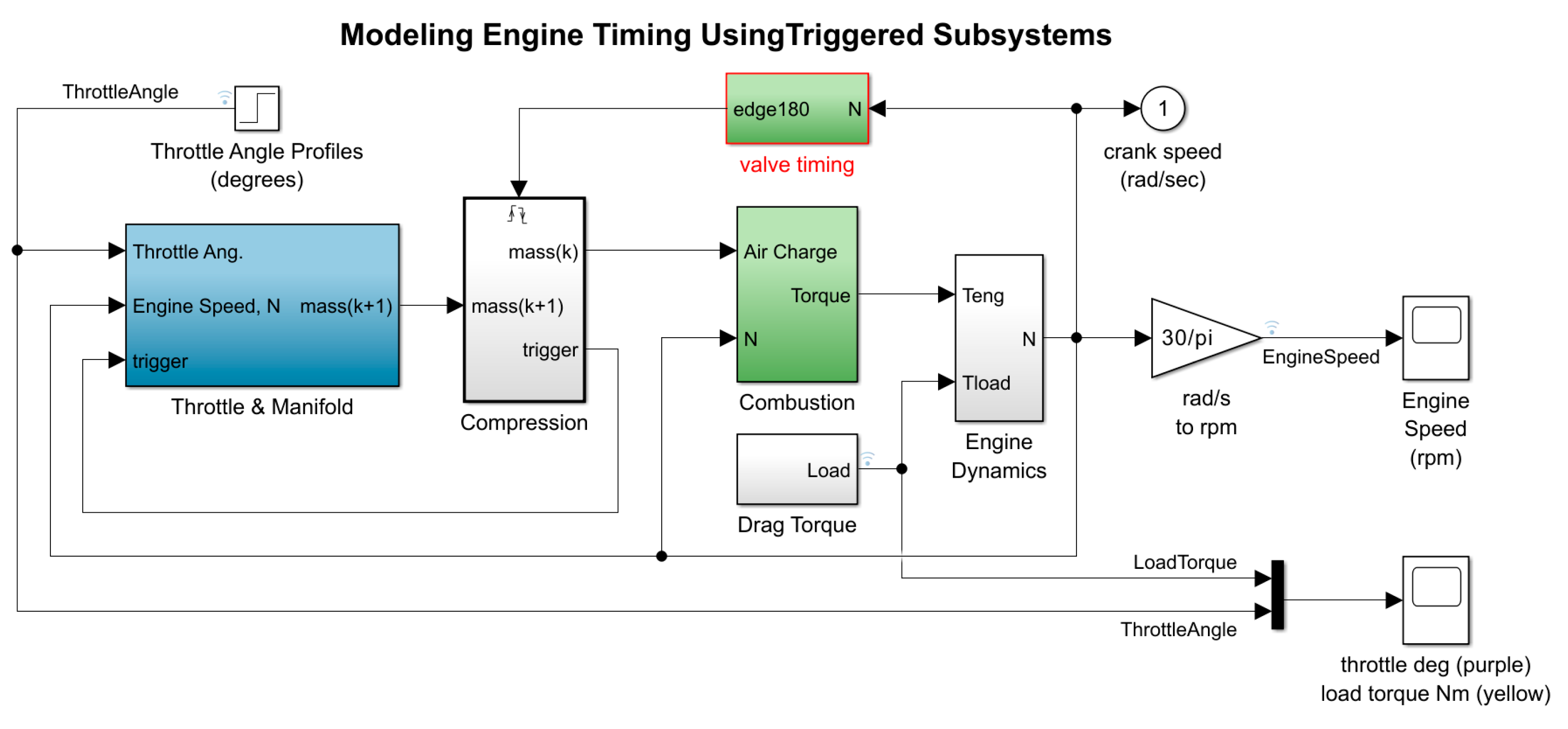
The MATLAB/Simulink (R2022b) tool was used to establish the models of the feedforward feedback closed-loop control system of a four-stroke gasoline engine, as shown in Figure 14. To start the simulation process, it is necessary to assign the initial speed N0 of the power unit, the target speed Ng (2000 rpm, 7000 rpm), and the initial carburetor opening θ(15°) and to set the load mutation rule (12 s mutation). The load carried by the generator is equivalent to the electromagnetic torque (0.75 Nm).
The simulation results show that when the load current feedforward compound speed feedback control loop is adopted, the speed overthrow is less than 12% during the load switching process, and the rated speed can still be maintained at 7000 rpm without shock under 100% heavy load mutation conditions, and the operation is stable. Compared with the conventional feedback control, the performance in all aspects has been greatly improved.
The open-loop and closed-loop engine speed response curve is shown in Figure 15.
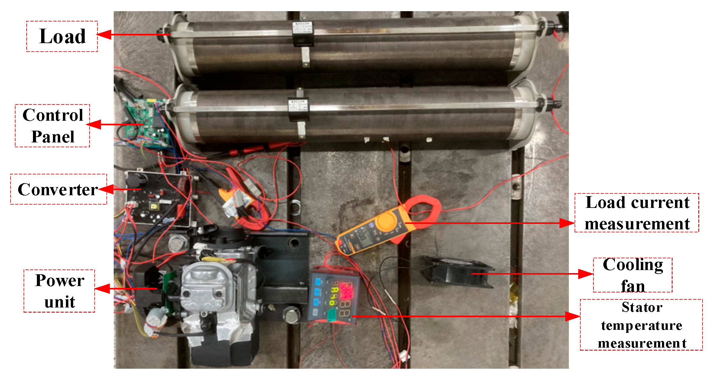
The practical generator set experiment platform is shown in Figure 16.
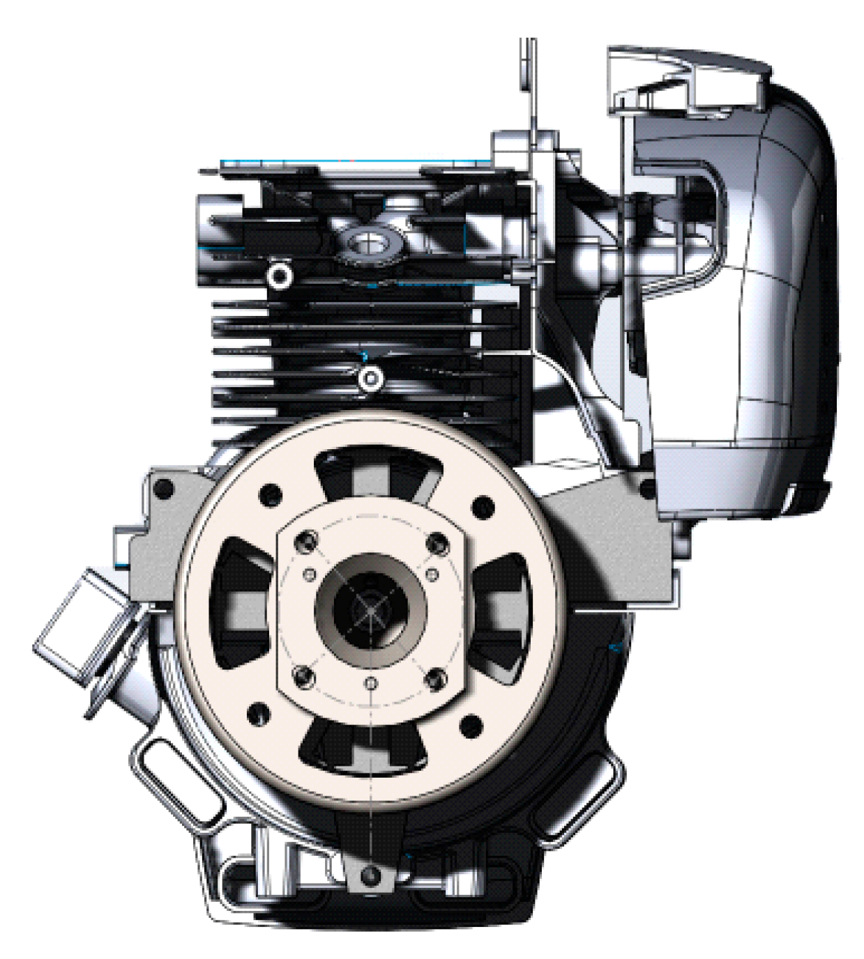
In order to verify the practicability of the algorithm, a machine matching experiment is carried out in the laboratory. The prototype used in the test was redesigned from a single-cylinder, air-cooled, four-stroke small gasoline engine produced by a machinery company. Removing the engine flywheel clutch parts and magneto modules, the cylinder diameter × stroke is 40 mm × 30 mm, the compression ratio is 8.5:1, and the rated output power is 0.85 kW (7000 rpm). In addition, a lot of tests have been carried out. Overall diagram of the generating unit is shown in Figure 17.
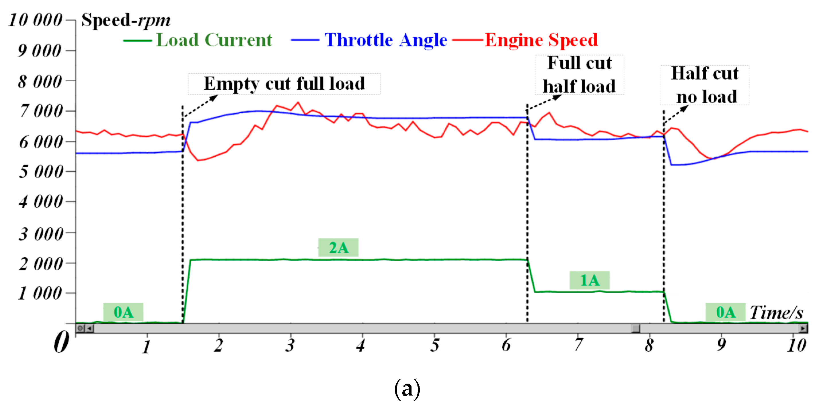
Figure 18a is the speed fluctuation curve when the load is abruptly applied, and Figure 18b is the speed fluctuation curve when the load is abruptly reduced. Table 3 shows the analysis of load current and carburetor opening test data related to steady state tests and transient tests. It can be seen that under the condition of a sudden load change, it has a fast speed stabilization ability. In particular, a full load full cut or full throw achieved a response recovery within 0.9 s.

5.2. Simulation Analysis of the Generator Control Strategy

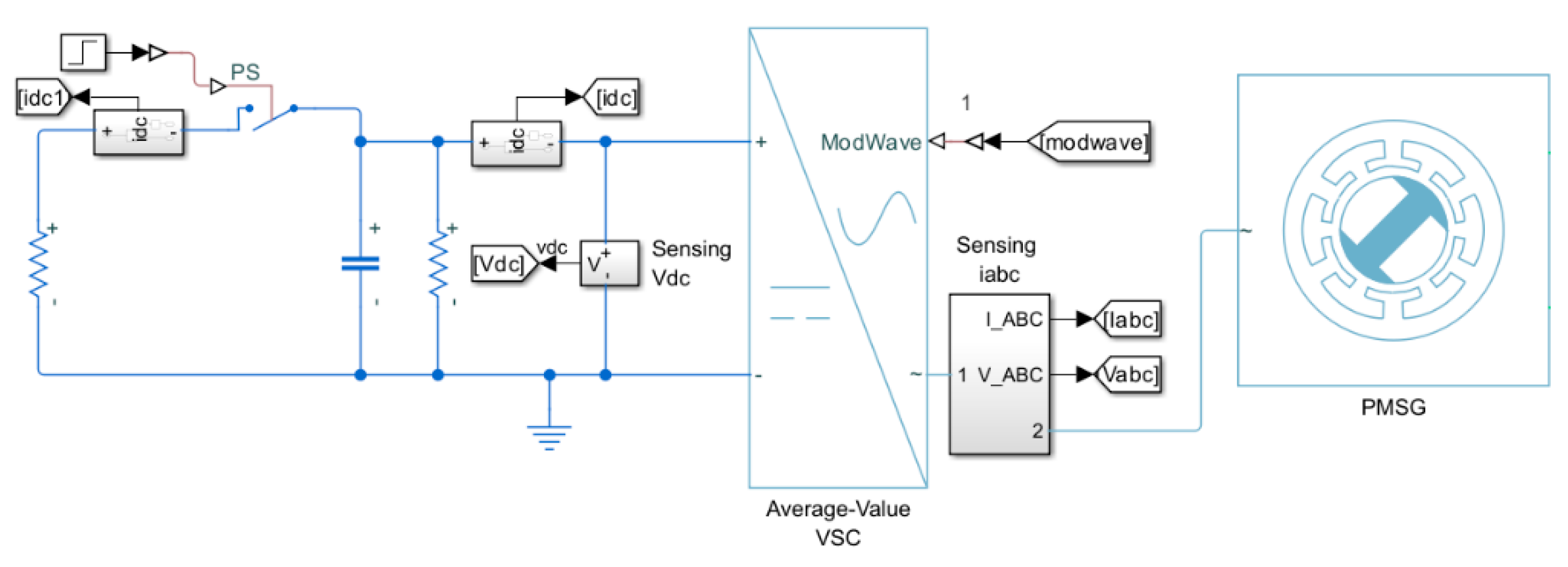
In order to verify the performance and effectiveness of the load torque observer and the designed generator control strategy, the MATLAB/Simulink platform was used to build a simulation model for simulation verification. Generator simulation parameters are shown in Table 3. According to the topology shown in Figure 1 and the proposed control strategy, the inverter AC output of the whole power generation system is simulated. The Simulink simulation diagram is shown in Figure 19.
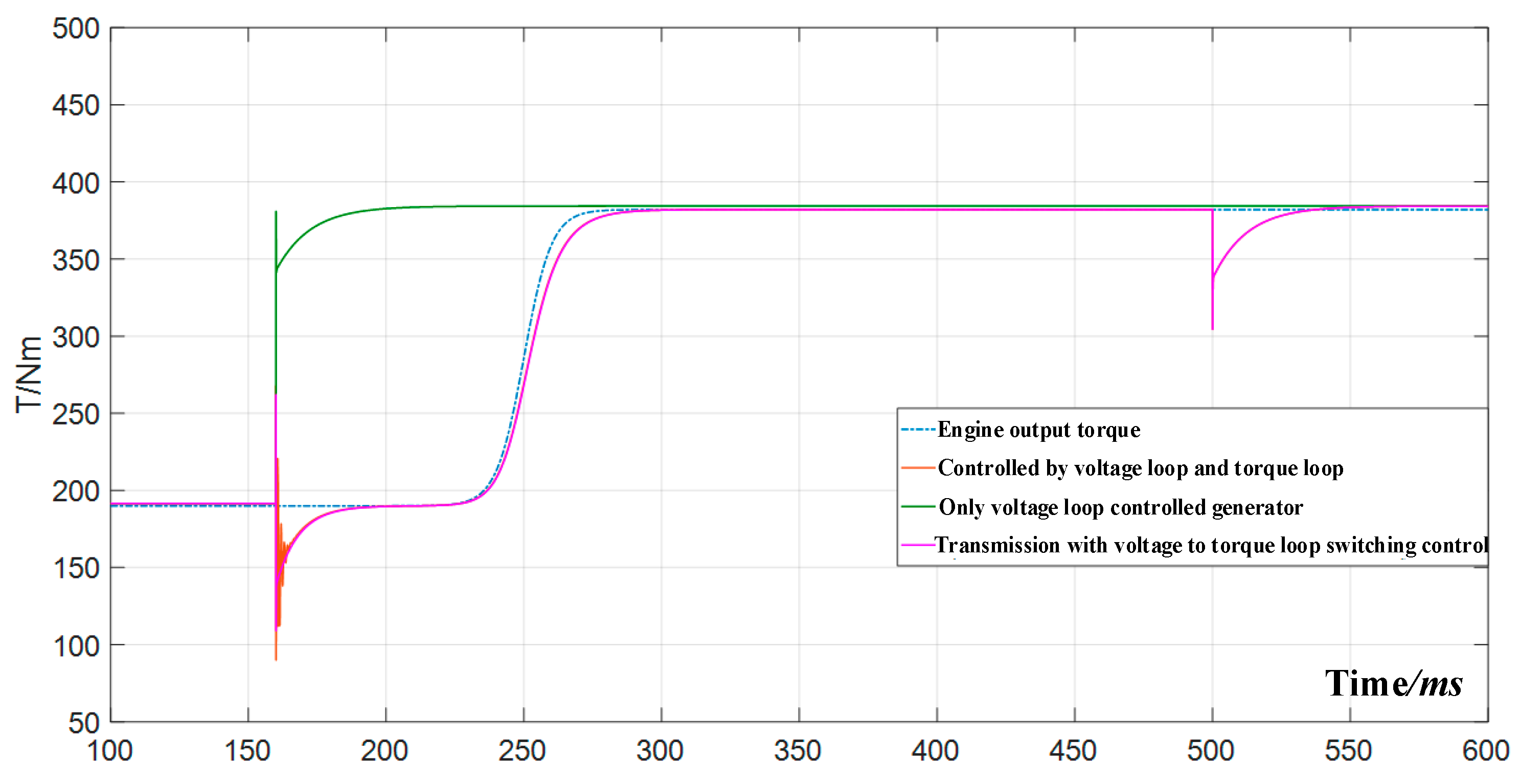
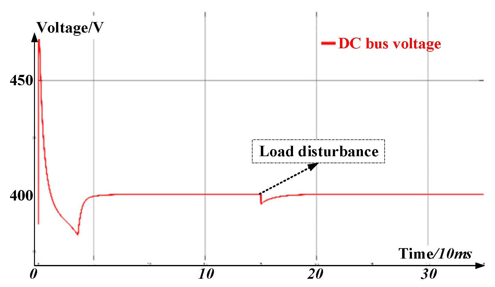
As can be seen from the figure, when the load is suddenly discharged and suddenly loaded, the load torque feedforward compensation is added, and the voltage fluctuation is reduced by an average of 12 V (full load fluctuation) compared with that when the traditional PI speed controller is used. In particular, considering the transient process of a sudden load change, the flow of the generator electromagnetic torque to the engine output torque is greatly improved, the introduction of a torque loop alleviates the torque imbalance between the generator and the engine, and the introduction of a feedforward term further alleviates the imbalance problem, where the degree of direct imbalance between the generator and the engine is represented by the instability parameter S. Relevant simulation waveforms are shown below. The simulation results show that the load torque feedforward compensation and torque loop switching control shorten the time for the system to recover to the stable state after the disturbance and improve the anti-load disturbance ability of the system. Comparison of the electromagnetic torque waveform under different control strategies is shown in Figure 20. DC-bus voltage waveform of system is shown in Figure 21.

5.3. Experimental Analysis of the Inverter Control Strategy

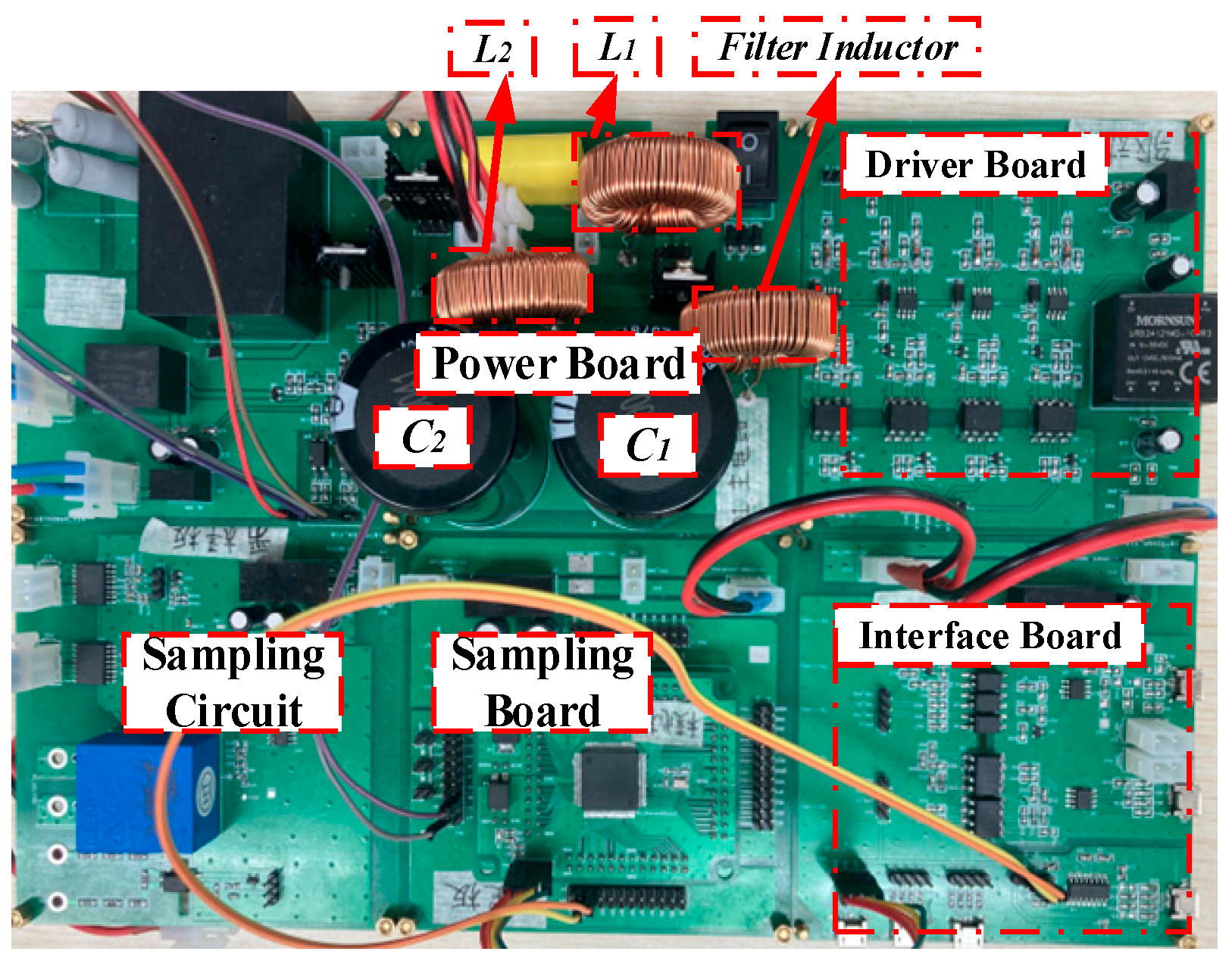
An inverter experiment platform based on the STM controller was built to verify the proposed inverter control strategy. The inverter platform, as shown in Figure 22, includes the main circuit of the dual buck topology inverter and the circuit parts related to the control and communication modules.
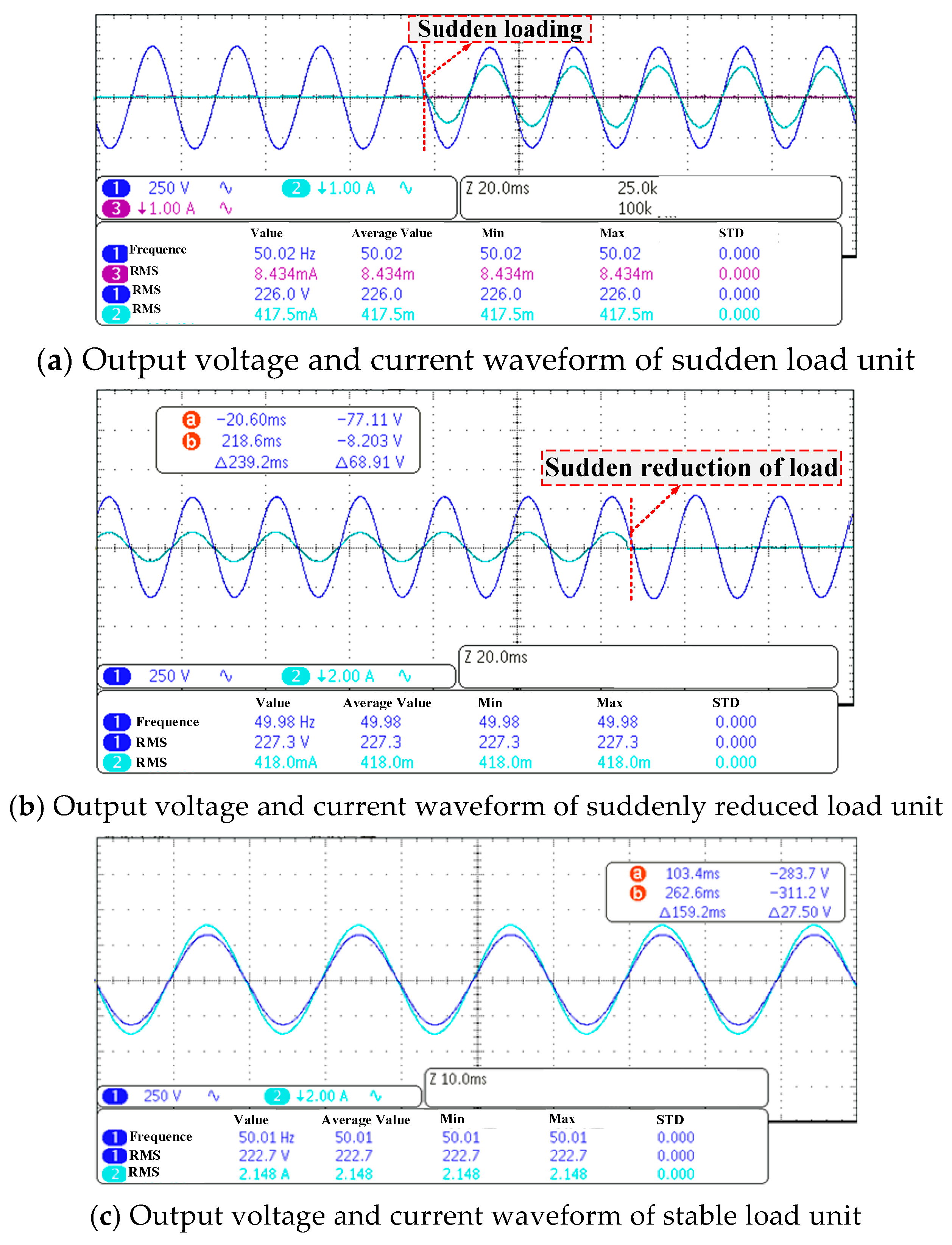
The experimental waveform results are as follows. Whether it is sudden load or sudden load reduction, or even considering 100% load change, the inverter can always restore the normal waveform output within 5 ms. In addition, the transient process of 5 ms can be ignored, the overall voltage waveform quality is high, and the average THD is within 0.7%. Actual output waveform of the dual buck inverter is shown in Figure 23.

6. Conclusions

This paper analyzes the internal mechanism of the specific practical engineering problems in the three components of the ultralight mobile power generation system, selects several typical faults in the experiment, establishes the corresponding mathematical models, and designs the response control strategy based on the models. As for the engine process, the mechanism of the whole process of engine stoppage or a speed problem caused by load switching or shutdown is analyzed in this paper, the time-sequence analysis diagram of response is given, and the engine control strategy based on load current feedforward and speed feedback is designed. As for the generator link, the connection shaft breaks or stops due to the mismatch between the generator’s electromagnetic torque and the engine’s output torque in the transient process. This paper analyzes the problem and the failure mechanism of the direct cause and designs an electromagnetic torque observer as a torque feedforward quantity to improve the control response time. Moreover, the strategy of switching between the electromagnetic torque loop and the bus voltage loop is adapted to take into account the stability of the bus voltage and the torque balance between the generator and engine. As for the inverter, considering the stability problem, the double buck inverter topology is adopted to avoid the problem of the bridge arm straight through, and the feedback linearization method based on differential geometry is designed to improve the power quality of the AC inverter output. Finally, this paper verifies the three proposed control strategies and the degree of problem-solving through simulation and experiment and proves the effectiveness and practicability of the proposed strategies.

Author Contributions

Methodology, P.W.; Software, P.W.; Validation, P.W.; Formal analysis, P.W.; Resources, P.W.; Writing—original draft, P.W.; Writing—review & editing, P.W.; Supervision, Z.Y. (Zhibao Yuan); Project administration, H.X.; Funding acquisition, Z.Y. (Zengquan Yuan). All authors have read and agreed to the published version of the manuscript.

Funding

This work was supported by the Research Fund of Institute of Electrical Engineering, Chinese Academy of Sciences (E21Z350101).

Data Availability Statement

Data are contained within the article.

Conflicts of Interest

The authors declare no conflict of interest.

References

  1. Chinchilla, M.; Arnaltes, S.; Burgos, J.C. Control of permanent-magnet generators applied to variablespeed wind-energy systems connected to the grid. IEEE Trans. Energy Convers. 2006, 21, 130–135. [Google Scholar] [CrossRef]
  2. Kendouli, F.; Abed, K.; Nabti, K.; Benalla, H.; Azoui, B. High performance PWM converter control based PMSG for variable speed wind turbine. In Proceedings of the 2012 First International Conference on Renewable Energies and Vehicular Technology, Nabeul, Tunisia, 26–28 March 2012; pp. 502–507. [Google Scholar]
  3. Ovacik, L.; Bilgin, B. Developments in voltage regulation of variable-speed PM synchronous alternators in automotive electric systems. In Proceedings of the 2011 International Conference on Applied Electronics, Pilsen, Czech Republic, 7–8 September 2011; pp. 1–6. [Google Scholar]
  4. Burrow, S.G.; Mellor, P.H.; Churn, P.; Sawata, T.; Holme, M. Sensorless operation of a permanent-magnet generator for aircraft. IEEE Trans. Ind. Appl. 2008, 44, 101–107. [Google Scholar] [CrossRef]
  5. Ge, X.; Shi, Y.; Yan, F.; Zhu, X.; Liu, C. Research on Control Inertia and Stability of PMSG. Electronics 2022, 11, 1583. [Google Scholar] [CrossRef]
  6. Miao, L.; Lin, F.; Jiang, Y.; Li, Q.; Sun, W. Dynamic Operation Loss Minimization for Permanent Magnet Synchronous Generator Based on Improved Model Predictive Direct Torque Control. Electronics 2022, 11, 1406. [Google Scholar] [CrossRef]
  7. Lee, J.-H.; Lee, H.-K.; Lee, Y.-G.; Lee, J.-I.; Jo, S.-T.; Kim, K.-H.; Park, J.-Y.; Choi, J.-Y. Design and Analysis Considering Magnet Usage of Permanent Magnet Synchronous Generator Using Analytical Method. Electronics 2022, 11, 205. [Google Scholar]
  8. Shen, J.; Miao, D.M. Machine design and control strategy for wide-speed-range PMSG systems. COMPEL Int. J. Comput. Math. Electr. Electron. Eng. 2015, 34, 92–109. [Google Scholar] [CrossRef]
  9. Miao, D.M.; Shen, J.X. Simulation and analysis of a variable speed permanent magnet synchronous generator with flux weakening control. In Proceedings of the 2012 International Conference on Renewable Energy Research and Applications (ICRERA), Nagasaki, Japan, 11–14 November 2012; pp. 1–6. [Google Scholar]
  10. Malinowski, M.; Kazmierkowski, M.P.; Trzynadlowski, A.M. A comparative study of control techniques for PWM rectifiers in AC adjustable speed drives. IEEE Trans. Power Electron. 2003, 18, 1390–1396. [Google Scholar] [CrossRef]
  11. Malinowski, M.; Kazmierkowski, M.P.; Hansen, S.; Blaabjerg, F.; Marques, G.D. Virtual-flux-based direct power control of three-phase PWM rectifiers. IEEE Trans. Ind. Appl. 2001, 37, 1019–1027. [Google Scholar] [CrossRef]
  12. Zhi, D.; Xu, L.; Williams, B.W. Improved direct power control of grid-connected DC-AC converters. IEEE Trans. Power Electron. 2009, 24, 1280–1292. [Google Scholar] [CrossRef]
  13. Liu, J.; He, J.; Iu, H.H.-C. Realization of Low-Voltage and High-Current Rectifier Module Control System Based on Nonlinear Feed-Forward PID Control. Electronics 2021, 10, 2138. [Google Scholar] [CrossRef]
  14. Liu, J.; Qu, X.; Iu, H.H.-C. Synchronous Generator Rectification System Based on Double Closed-Loop Control of Backstepping and Sliding Mode Variable Structure. Electronics 2021, 10, 1832. [Google Scholar] [CrossRef]
  15. Amin, M.M.N.; Mohammed, O.A. DC-bus voltage control technique for parallel-integrated permanent magnet wind generation systems. IEEE Trans. Energy Convers. 2011, 26, 1140–1150. [Google Scholar] [CrossRef]
  16. Wang, Y.; Deng, Z.; Wang, X. A parallel hybrid excitation flux-switching generator dc power system based on direct torque linear control. IEEE Trans. Energy Convers. 2012, 27, 308–317. [Google Scholar] [CrossRef]
  17. Miao, D.M.; Mollet, Y.; Gyselinck, J.; Shen, J.X. DC voltage control of a wide-speed-range permanentmagnet synchronous generator system for more electric aircraft applications. In Proceedings of the 2016 IEEE Vehicle Power and Propulsion Conference (VPPC), Hangzhou, China, 17–20 October 2016. [Google Scholar]
  18. Miao, D.M.; Mollet, Y.; Shen, J.X.; Gyselinck, J. Direct voltage field-oriented control for permanent-magnet synchronous generator systems with an active rectifier. In Proceedings of the 2016 IEEE International Energy Conference (ENERGYCON), Leuven, Belgium, 4–8 April 2016; pp. 1–6. [Google Scholar]
  19. Miao, D.M.; Shen, J.X. Direct voltage control strategies for variable-speed permanent magnet synchronous generator system. In Proceedings of the 10th International Conference on Ecological Vehicles and Renewable Energies (EVER), Monte Carlo, Monaco, 31 March–2 April 2015; pp. 1–6. [Google Scholar]
  20. Thayumanavan, P.; Kaliyaperumal, D.; Subramaniam, U.; Bhaskar, M.S.; Padmanaban, S.; Leonowicz, Z.; Mitolo, M. Combined Harmonic Reduction and DC Voltage Regulation of a Single DC Source Five-Level Multilevel Inverter for Wind Electric System. Electronics 2020, 9, 979. [Google Scholar] [CrossRef]
  21. Loncarski, J.; Hussain, H.A.; Bellini, A. Efficiency, Cost, and Volume Comparison of SiC-Based and IGBT-Based Full-Scale Converter in PMSG Wind Turbine. Electronics 2023, 12, 385. [Google Scholar] [CrossRef]
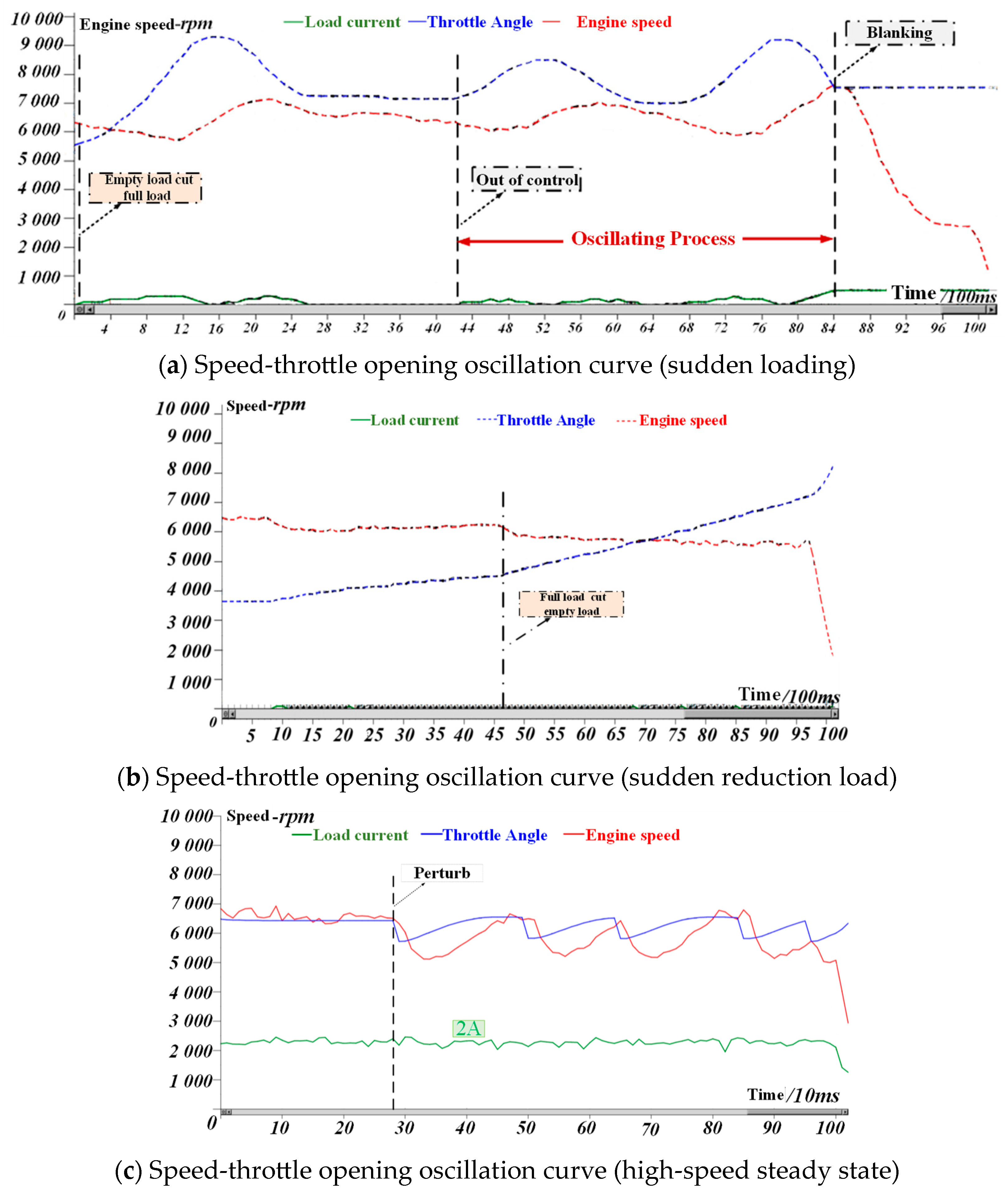
Figure 1. Loss of stability condition of speed control of the power unit.
Energies 17 01402 g001
Figure 2. Time sequence analysis diagram of the influence of a sudden load on the power unit.
Energies 17 01402 g002
Figure 3. Speed feedback control block diagram of the power unit.
Energies 17 01402 g003
Figure 4. Block diagram of the turboshaft engine cascade control system.
Energies 17 01402 g004
Figure 5. Generator-PWM rectifier structure.
Energies 17 01402 g005
Figure 6. Equivalent diagram and simplified diagram of the generator-PWM rectifier. (a) The d-axis equivalent circuit diagram. (b) The q-axis equivalent circuit diagram Tutu. (c) Generator-rectifier simplified mathematical model.
Energies 17 01402 g006
Figure 7. Observer principle and application design. (a) Observer principle. (b) Design of the load current observer.
Energies 17 01402 g007
Figure 8. Controlled system with load current observer.
Energies 17 01402 g008
Figure 9. Block diagram of the torque coordination matching control strategy of the series-connected power unit based on the load current observer.
Energies 17 01402 g009
Figure 10. Dual buck inverter.
Energies 17 01402 g010
Figure 11. Equivalent model of dual buck inverter.
Energies 17 01402 g011
Figure 12. Circuit and equivalent schematic diagram in different working conditions. (a) Inductor L1 charging. (b) Inductor L1 discharging. (c) Inductor L2 charging (d) Inductor L2 discharging. (e) Inductor charging equivalent circuit. (f) Inductor discharging equivalent circuit.
Energies 17 01402 g012
Figure 13. Block diagram of the main circuit system.
Energies 17 01402 g013
Figure 14. Simulation model of the speed regulation system.
Energies 17 01402 g014
Figure 15. Open-loop and closed-loop engine speed response.
Energies 17 01402 g015
Figure 16. Generator set experiment platform.
Energies 17 01402 g016
Figure 17. Overall diagram of the generating unit (engine–generator).
Energies 17 01402 g017
Figure 18. Optimization results of speed regulation of the power unit of the generator set. (a) Load switching speed regulation process (sudden increase and decrease). (b) Load switching speed regulation process (sudden reduction full load).
Energies 17 01402 g018aEnergies 17 01402 g018b
Figure 19. Power unit (PMSG)-rectifier simulation model.
Energies 17 01402 g019
Figure 20. Comparison of the electromagnetic torque waveform under different control strategies (torque × 500).
Energies 17 01402 g020
Figure 21. DC-bus voltage waveform of system (under optimization strategy).
Energies 17 01402 g021
Figure 22. Dual buck inverter main circuit and controller diagram.
Energies 17 01402 g022
Figure 23. Actual output waveform of dual buck inverter.
Energies 17 01402 g023
Table 1. Variables in the engine speed control model.
SymbolSignificanceSymbolSignificance
thoEngine throttle angleTeElectromagnetic torque of generator
TEngEngine torqueTDEngTime constant of the engine inertia link
ωErealActual speed of power unitωEngTarget speed of the power unit
PoTarget loading powerJInertia of the output shaft
Table 2. Parameters in the control block diagram.
ArgumentNumerical ValueArgumentNumerical Value
Power unit output shaft moment of inertia J1.82 × 10−3
(kg·m2)
Torque–speed ratio K7.6 × 10−4
Delay factor TDEng0.4Steady speed value7000
Proportional coefficient kp0.2Integral coefficient ki0.008
Table 3. Parameters in the model experimental test.
ParametersValueParametersValue
Stator equivalent inductance Ld/(mH)7.79Number of poles5.0
Stator equivalent resistance/(Ω)5.84Rotor equivalent resistance/(Ω)3.89
Rated speed/(rpm)7000Rated torque/(N·m)0.5
Rotor equivalent inductance Ld/(mH)7.79Mutual inductance/mH0.39
Permanent magnet flux linkage ψf/(Wb)0.59Moment of inertia/(kg·m2)0.008
Disclaimer/Publisher’s Note: The statements, opinions and data contained in all publications are solely those of the individual author(s) and contributor(s) and not of MDPI and/or the editor(s). MDPI and/or the editor(s) disclaim responsibility for any injury to people or property resulting from any ideas, methods, instructions or products referred to in the content.