Article

Partial Separation of Carbonated Material to Improve the Efficiency of Calcium Looping for the Thermochemical Storage of Solar Energy

1
Departamento de Ingeniería Mecánica, Escuela de Ingeniería y Arquitectura (EINA), Universidad de Zaragoza, C/María de Luna s/n, 50018 Zaragoza, Spain
2
Dipartimento di Ingegneria, Università degli Studi del Sannio, Piazza Roma 21, 82100 Benevento, Italy
3
Istituto di Scienze e Tecnologie per l’Energia e la Mobilità Sostenibili, Consiglio Nazionale delle Ricerche, Piazzale Tecchio 80, 80125 Napoli, Italy
4
Dipartimento di Ingegneria Chimica, dei Materiali e della Produzione Industriale, Università degli Studi di Napoli Federico II, Piazzale Tecchio 80, 80125 Napoli, Italy
5
Dipartimento di Scienze Chimiche, Università degli Studi di Napoli Federico II, Complesso Universitario di Monte Sant’Angelo, 80126 Napoli, Italy
*
Author to whom correspondence should be addressed.
Energies 2024, 17(6), 1372; https://doi.org/10.3390/en17061372
Submission received: 1 February 2024 / Revised: 7 March 2024 / Accepted: 8 March 2024 / Published: 13 March 2024
(This article belongs to the Section A2: Solar Energy and Photovoltaic Systems)

Abstract

:
Concentrating solar power (CSP) technology with thermal energy storage (TES) could contribute to achieving a net zero emissions scenario by 2050. Calcium looping (CaL) is one of the potential TES processes for the future generation of CSP plants coupled with highly efficient power cycles. Research on CaL as a system for thermochemical energy storage (TCES) has focused on efficiency enhancement based on hybridization with other renewable technologies. This work proposes a novel solid management system to improve the efficiency of a CaL TCES system. The inclusion of a solid–solid separation unit after the carbonation step could lead to energy and size savings. The role of segregation between carbonated and calcined material on plant requirements is assessed, given the experimental evidence on the potential classification between more and less carbonated particles. The results show lower energy (up to 12%) and size (up to 76%) demands when the circulation of less carbonated material through the CaL TCES system diminishes. Moreover, under a classification effectiveness of 100%, the retrieval energy could increase by 32%, and the stored energy is enhanced by five times. The present work can be a proper tool to set the design and size of a CaL TCES system with a partial separation of the carbonated material.

1. Introduction

One of the tools to fight against climate change is the massive deployment of renewable energy technologies within the energy mix, as highlighted by the Intergovernmental Panel on Climate Change [1]. A carbon neutrality scenario by 2050 could be achieved, increasing the global renewable power capacity by 2.5 times compared to 2022 [2]. A total of 30% of global electricity production since 2022 has originated from renewable energy sources. Solar photovoltaic (PV) and wind power are the most valuable technologies in current renewable electricity production [3]. However, their inherent intermittence in energy production has led to promote hybridization with concentrating solar power (CSP) technology [4]. Almost all new CSP plants include thermal energy storage (TES) to improve their energy dispatch capacity. The implementation of hybrid CSP with solar PV and wind power drives a faster drop in CO2 emissions [4] and costs [3,5]. Moreover, the electricity cost of CSP plants with TES diminished by up to 68% from 2010 to 2021, enhancing their capacity factor [3]. The energy storage could be a solution for the intermittency in energy production by renewable technologies, as already proposed by organizations such as the European commission [6,7] or the international energy agency [2].
Thermal energy storage (TES) is integrated into CSP plants to produce electricity using a coupled power block when solar energy is unavailable [8]. The stored energy is influenced by the thermophysical properties of the storage material [9]. The most commercial and low-cost storage material is molten salt, storing sensible heat by heating and cooling the medium. However, molten salts can suffer degradation when temperatures are above 565 °C and solidification at temperatures below 290 °C [10]. Similarly, the low thermal conductivity and low stability at high temperatures hinder the potential integration of phase-change materials into CSP plants [11,12]. Thermal energy storage (TES) materials supporting higher working temperatures would be required for the next generation of CSP plants featuring more efficient integrated power cycles [13]. The thermochemical energy storage (TCES) system meets the requirements for future CSP plants, being high-temperature systems (above 800 °C) based on the reversibility of chemical reactions [14,15]. In this process, the heat needed to sustain an endothermic reaction is provided by solar energy, which is then stored in the noble form of chemical bonds. When energy is required, the reaction products are gathered together to conduct the exothermic phase, regenerate the reagents, and start a new thermochemical cycle [16]. One of the most promising TCES systems is the calcium looping (CaL) process, which is based on the gas–solid calcination/carbonation reversible cyclic reaction. Calcium looping (CaL) has been deeply investigated in the literature for carbon capture and concentrated release (i.e., CO2 from the exhaust gases of fossil fuel combustion [17], CO2 from the atmosphere [18] and CO2 from bioenergy to achieve negative emission systems [19,20]). Current investigations are also focused on the potential use of the CaL process as a TCES system integrated into CSP plants [21,22]. The calcination step (Equation (1)) is endothermic and forms CO2 and calcium oxide (CaO); the exothermic carbonation step, reverse Equation (1), releases thermal energy through the partial reaction of CaO and CO2 to obtain partially carbonated material.
CaCO 3   s   CaO s + CO 2   g H R 0 = + 178   kJ / mol
CaO sorbent activity during carbonation is influenced by the operating conditions during the carbonation and calcination steps. The CaL process as a CO2 capture system performs (i) the carbonation reaction at 650 °C under a CO2 atmosphere of 10–15% [23] and (ii) the calcination reaction at 950 °C and a high CO2 concentration [24]. The reached temperature for TCES applications may be 850 °C and 950 °C with a pure CO2 atmosphere for the carbonation and calcination reactions, respectively [25].
The main advantages of the CaL process for TCES applications for CSP plants are: (i) the high reaction enthalpy (Equation (1)), (ii) the high working temperature achievable (up to 850 °C) to couple more efficient power cycles [26], and (iii) the sorbent material characteristics (non-toxic, Earth-abundant and cheap) [27,28]. However, the sorbent capacity decays with carbonation/calcination cycles given the high working temperature [29,30]. Thermal and chemical sintering results in a loss of porosity and the pore plugging of the sorbent, limiting its performance [31,32,33]. The enhancement of CaL sorbent conversion under TCES conditions was recently researched, developing techniques based on: (i) thermal [34] and steam [35,36] pretreatments, (ii) the use of synthetic [37,38,39] and doped [39,40] sorbents, (iii) or low-pressure conditions during the calcination step [41]. Moreover, the loss of sorbent activity has been widely investigated, developing well-adjusted carbonation kinetic models using thermogravimetric analysis (TGA) experimental data under carbon capture and TCES conditions [23,42,43]. Since TGA tests do not reflect the potential thermal stress suffered by the sorbent on a larger scale [44], novel robust carbonation models are required for TCES applications. Tregambi et al. proposed a new deactivation model based on the experimental data obtained under TCES conditions in lab-scale facilities whose operating pattern was close to large-scale [45].
Regarding the integration of the CaL process in the CSP plant, several schemes have been proposed in the literature. Most of the research comprehends the hybridization of the CSP plant with (i) other renewable technologies (i.e., solar PV [46,47]), (ii) combined power cycles [41,48,49], or (iii) power-to-gas technology [50] to improve the capacity factor. Hybrid solar PV-CSP, proposed by Bravo et al., supplies energy demand by both plants, partially storing thermal energy in the CaL process as TCES system. The stored energy is later discharged to cover the nighttime energy demand [46,47]. Ortiz et al. proposed a novel CSP hybridization model to supply energy demand during the day through a combined power block and to store thermal energy using a CaL TCES system. When solar energy is unavailable and the CSP plant is shut down, the energy demand is supplied by the CaL TCES system [41,48,49]. A methanation plant was designed by Tregambi et al. using a CSP plant with a CaL TCES system to enhance the renewable share. The CaL process worked as a carbon capture system and TCES system during sunlight hours, and the calcination energy demand was supplied by the CSP plant. The CO2 capture continued during the night period, discharging the stored energy in the TCES system. The CO2 captured (and correspondingly released in a concentrated stream) was used to produce methane using power-to-gas technology [50]. Thus, these investigations focused on the hybridization of CSP with other power plants, extending the dispatch capacity when the solar resource is unavailable. The electricity demand pattern and the solar resource variability were the inputs for a novel dynamic operational methodology developed by Pascual et al. [51] based on the maximization of the efficiency and the economic revenue of the CSP plant. The operating pattern and the real behavior of a CaL TCES system without power supply backup were defined, promoting the proper design and sizing of the CaL TCES system [51].
Most of the CaL TCES process schemes presented in the literature have a common characteristic. The partially carbonated material found after the carbonation step circulates between the calciner and carbonator reactors and through the storage system. The solids found after the carbonation reaction are a mixture of more and less carbonated particles. The circulation of the less carbonated or unconverted material could diminish the process efficiency [52]. A mixture of carbonated and non-carbonated material leaves the carbonator reactor, given the effect of sintering on CaO reactivity. The main factors influencing CaO activity are (i) the nature of the bed and (ii) the temperature achieved during the carbonation-calcination reactions in fluidized beds (i.e., 850 °C for carbonation and 950 °C for calcination). A less intense sintering effect occurs in limestone-only beds. The high operating temperatures under calcination and carbonation cycles increase thermal sintering, leading to higher particle density and lower reactive porosity [53]. Moreover, the lower the sorbent conversion, the greater the amount of inert material circulating in the system [54]. Pascual et al. simulated a novel solid management configuration to enhance the CaL TCES process efficiency. The inclusion of new equipment after the carbonation step could separate the unconverted material from the carbonated solids, recirculating the unreacted particles into the carbonator [55]. The threshold situations were computationally assessed, and it was found that there was no separation and total separation of the carbonated material. The results showed a wide difference in energy and size between both scenarios, reaching the maximum savings under the total and ideal separation configuration [56]. The potential separation between the carbonated and unconverted particles based on the density difference was experimentally assessed by Tregambi et al. [45] given the potential energy and size savings achievable in the CaL TCES system with the inclusion of a solid–solid separation unit [56]. A potential partial separation between more and less carbonated material was evidenced, given the difference between the experimental minimum fluidization velocity of carbonated and calcined material for the CaL process under TCES conditions [45]. Moreover, the segregation tests in a fluidization column equipped with a needle-type capacitive probe were performed by Di Lauro et al. to assess the technical feasibility of the inclusion of a solid–solid separation unit after the carbonation step. The required minimum superficial gas velocity to classify the low-cycled material was experimentally measured, given the favorable gap between the minimum fluidization velocities for more and less carbonated material. The results show the potential segregation of less carbonated particles that, having a lower density, are characterized by a lower minimum fluidization velocity and tend to segregate to the upper part of the bed (flotsam). On the contrary, the more carbonated particles, characterized by higher minimum fluidization velocities, tend to segregate to the bottom of the bed (jetsam) [53]. However, the energy and size requirements of the CaL TCES system with the potential partial separation of the carbonated material still need to be addressed.
The aim of the present work was to define the CaL TCES plant demands under a range between the two threshold scenarios: no and total separation. Moreover, the separation effectiveness of a potential solid–solid classifier was assessed under different levels of partial separation of carbonated material. The specific thermal consumptions and energy storage were addressed under all ranges for partial separation. The present study helps to develop a future separation system based on a solid–solid classifier via a density difference. The actual classification effectiveness would depend on the characteristics of the particles to be separated. This study serves as a direct tool for the CaL TCES system design corresponding to a given separation effectiveness.

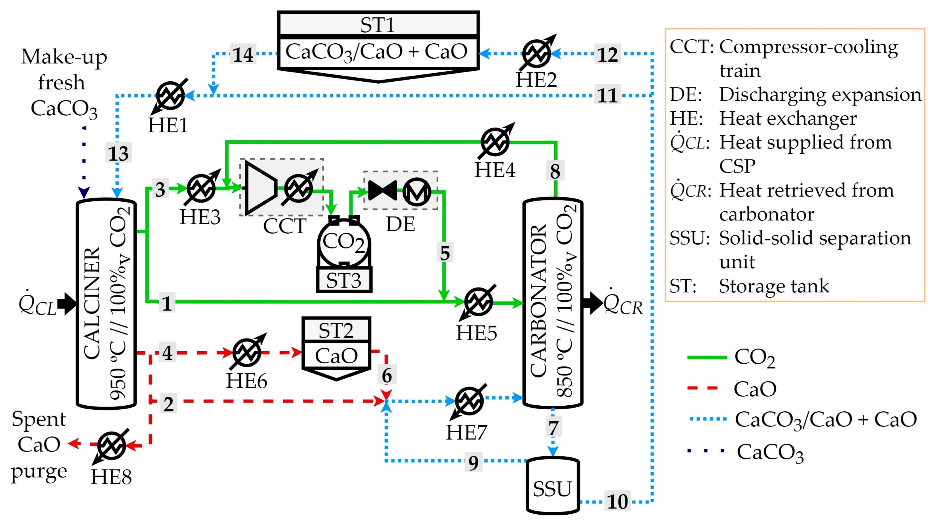
2. Case Study: The Partial Separation of Carbonated Solids in a CaL TCES System

The CaL TCES process scheme to assess the effects of the partial separation of carbonated material is shown in Figure 1. The storage tank (ST) system was included between the two main reactors (i.e., the solar calciner and carbonator) with an intermediate heat exchange (HE) network for preheating or heat recovery with 2% energy losses. The reactors were based on fluidized bed technology, and CO2 was the fluidization gas used to perform the heterogeneous reactions of calcination and carbonation. The nominal power of the solar calciner was set to 100 MW. When solar energy was available (defining Q ˙ CL as the heat power required by the calciner), the endothermic calcination reaction occurred at 950 °C and 100% pure CO2 atmosphere, forming CaO and CO2 as the products (the reaction was completely shifted towards the products). The gas and lime (CaO) particles leaving the calciner could be sent to independent storage tanks (i.e., ST2 for CaO and ST3 for CO2) or be fed to the carbonator (streams 1 and 2, respectively). The CO2 stream directed to the storage (stream 3) was sent to a compressor and cooling train (CCT) to reach the ST3 storage conditions (35 °C and 75 bar). Before the CCT process, the heat exchanger named HE3 cooled the CO2 stream from 950 to 50 °C. Moreover, CO2 storage was required to release the energy stored in CaO in the carbonator later. The CaO stream was cooled from 950 to 200 °C in the HE6 to be sent to the ST2 storage tank (stream 4) or fed to the carbonator (stream 2). When energy recovery was required in the carbonator ( Q ˙ CR is the related power), CaO and CO2 were fed to the carbonator from the storage tanks or calciner. The HE5 heat exchanger preheated up to 850 °C the CO2 streams from (i) the calciner at 950 °C (stream 1) and (ii) the discharging expansion (DE) process (15 °C) after the ST3 storage tank (stream 5). The HE7 heat exchanger preheated up to the carbonator temperature (850 °C), the mixture of CaO particles from the calciner at 950 °C (stream 2), and the ST2 storage tank at 200 °C (stream 6). The non-complete exothermic heterogeneous carbonation reaction involved finding partially carbonated material (stream 7) and unreacted CO2 (stream 8) as the carbonator outputs [57]. The unreacted CO2 (stream 8) was sent to the CCT to be stored at ST3 after a heat recovery in HE4 from 850 to 50 °C. The partially carbonated material consisted of a mixture of partially carbonated particles (CaO core with a CaCO3 shell) and less carbonated particles (mostly based on the unreacted CaO). For the first time, Pascual et al. [55] proposed the inclusion of a new equipment piece named the solid separation unit (SSU) to classify the partially carbonated material after the carbonation step. A total separation of more carbonated material from the lesser one was simulated by Pascual et al. [56] to assess the maximum energy and size savings compared to a reference case without any separation. The recirculation of the fewer carbonated particles into the carbonator was assumed, reaching a size reduction of up to 74% and energy savings of up to 28% when the SSU was implemented [56].
Two threshold scenarios (no and total separation) were evaluated to identify the maximum and minimum energy and size requirements. Moreover, the potential separation of the carbonated material was experimentally assessed by Tregambi et al. [45] and Di Lauro et al. [53]. The difference in the minimum fluidization velocity between the calcined and carbonated particles evidenced the possibility of a potential partial separation between more and less carbonated particles. Thus, different separation degrees were assessed in the present work to understand the effects on the plant sizing and energy requirements. The solid material recirculated to the carbonator from the SSU at 850 °C may have been rich in fewer carbonated particles (stream 9), while the solid material stream that leaves the SSU with a higher concentration of partially carbonated particles (stream 10) could be directed to the calciner (stream 11) or to the ST1 storage tank (stream 12) after cooling in the HE2 heat exchanger from 850 to 200 °C. Thus, the solids fed to the calciner (stream 13) were provided by the ST1 storage tank after preheating from 200 to 850 °C in HE1 (stream 14) or directly from the carbonator (stream 11) to close the loop.

2.1. Carbonation Modelling

The incomplete exothermic carbonation reaction occurred at 850 °C under a 100% CO2 atmosphere with a pressure of 1.2 bar to ensure the solid circulation between the reactors [58]. Since the sorbent deactivates with the number of cycles N [50], a stream of fresh limestone was fed to the calciner at 25 °C, and the spent material was purged to keep a reasonable average sorbent activity for the particle population. The heat recovery of the spent material from 950 to 200 °C was performed, as shown in Figure 1. The average sorption activity was calculated in terms of the CaO carbonation degree (X) applying Equation (2), where r N is the age distribution of the sorbent population (expressed as a fraction of the particles subjected to N cycles) and X N represents the degree of CaO carbonation at cycle N. The age distribution was calculated under conservative carbon capture conditions, applying Equation (3) [59]. The carbonation degree ( X N ) under each cycle N was defined using a novel activity decay (IAD) model [45].
X ave = 1 r N · X N
r N = f p ( 1 + f p ) N

2.1.1. Novel Initial Activity Decay Model

The activity decay upon cycling was estimated by applying a novel IAD model as in Tregambi et al., Equation (4) [45], where k 1 is the initial activity constant (X1 = k1) and k 2 is the activity decay constant (the higher the k 2 , the worse the sorbent resistance to deactivation). Both parameters were set to the values obtained from the experimental data under CaL TCES conditions (i.e., 850 °C carbonation, 950 °C calcination and both under pure CO2 atmosphere) using a facility close to large-scale with a limestone bed inventory (i.e., k 1 = 0.62 and k 2 = 0.46 ). The experimental carbonation degree with the carbonation–calcination cycles was obtained from the test performed in an electrically heated fluidized bed. The novel IAD model was well-fitted to the experimental data [45].
X N = k 1 · N k 2

2.1.2. Carbon Capture Efficiency

The carbon capture efficiency ( η capt ) was calculated by applying Equation (5) as the product of the average sorption activity and the Ca (as CaO)/C (as CO2) molar ratio (R) as the input to the carbonator.
η capt = X ave · R
Carbonation modeling was first implemented on the CaL TCES scheme with the total separation of the carbonated material under nominal conditions as the base reference. A sensitivity assessment (Figure 2) was carried out to set the proper spent material purge fraction (fp; expressed vs. the recirculating sorbent, molar basis) to reach a carbon capture efficiency close to 90% and a suitable value for R. The value of R was subjected to the defined input variables of the CaL TCES system [51] including the (i) nominal power in the calciner ( Q ˙ CL), CaO purge fraction (fp), and analogous storage and discharge fractions of CO2 and CaO between the storage tanks and reactors, defining the CaO and CO2 fractions as the ratio of the mass flow rate conveyed to/from the storage tanks and the maximum mass flow rate that could be stored [55].
The small spent material purge (fp) and large Ca/C molar ratios (R) enhance the carbon capture efficiency but increase the system cost [60]. The economic viability of the system involves setting a purge value lower than 5% [60] and an R-value between 4 and 5 [60]. Therefore, a carbon capture efficiency of 96% with an average sorption activity of 20.2% could be achieved with a purge fraction (fp) of 4% and an R-value of 4.76 under the base reference (total separation of carbonated material). The Ca/C molar ratio of 4.76 was set as the input operation parameter for the CaL TCES system with the SSU implementation under the case of partially carbonated material separation.

3. Materials and Methods

This section includes the applied methods to assess the effect on plant dimensions, energy demands, and stored energy for different efficiencies of partial separation between more and less carbonated material. Engineering Equation Solver (EES) software (version number V9.944) was used to simulate the CaL TCES scheme under the partial separation of carbonated solids under nominal conditions (100 MW of solar energy in the calciner). The operation of the CaL TCES scheme was developed under threshold scenarios of no and total separation of the carbonated material in previous work [56]. The novelty of the present work is (i) the inclusion of a new IAD model for the carbonation step based on the experimental data [45] and (ii) the CaL TCES system energy and size assessment under the operating conditions of the partial separation of the carbonated material. The classification effectiveness, nominal size of the plant, calciner-specific energy consumption, and energy storage were the results of the applied methods based on the segregation level of more and less carbonated particles into the SSU.

3.1. Carbonated Material Separation Degree

Several operating scenarios for the SSU were assessed to understand the effect on the energy and size requirements of different degrees for the partial separation of the carbonated material. Although the CaL TCES system was designed to store energy, the calculations were applied to nominal conditions in both reactors without storage to define the CaL TCES system thresholds. The operation of the CaL TCES system under partial separation was influenced by the unreacted material circulating between the reactors and the higher number of carbonated particles recirculating into the carbonator. Thus, two variables were defined: the lower and higher carbonated material ratios. The lower carbonated material ratio ( η CaO , Equation (6)) is the mass flow rate of the unreacted material circulating in the CaL TCES system with respect to that of the lesser carbonated stream fed to the SSU from the carbonator ( m ˙ and χ represent, respectively, the mass flow rate and mass fraction). The second variable ( η CaCO 3 , Equation (7)) is the ratio between the mass flow rate of the greater carbonated particle stream recirculated into the carbonator and the mass flow rate of the higher number of carbonated particles fed to the SSU from the carbonator. The lower carbonated material ratio shows the unreacted material fraction conveyed through the CaL TCES system from the SSU, while the greater carbonated material ratio points out the fraction of the carbonated particles wthat arerecycled into the carbonator from the SSU. The lower the value of these ratios, the more efficient the CaL system TCES is; for η CaO = η CaCO 3 = 0, the total and ideal separation of the greater or lesser carbonated material was obtained.
η CaO = m ˙ SSU - CL · χ CaO , SSU - CL m ˙ SSU · χ CaO , SSU
η CaCO 3 = m ˙ SSU - CR · χ CaCO 3 , SSU - CR m ˙ SSU · χ CaCO 3 , SSU
The experimental minimum fluidization velocity data obtained by Tregambi et al. [45] led to a potential partial separation between more and less carbonated particles. The new SSU equipment proposed by Pascual et al. [55] could be based on a solid–solid classifier. A tapered fluidized bed reactor could induce the segregation of fewer carbonated particles with a lower density to the top of the reactor when the operation regime is under transient fluidization [61]. The global classification effectiveness E was computed using Equation (8), which was implemented for tapered fluidized bed reactors to identify the efficiency degree of material separation [61].
E = E CaCO 3 · E CaO =   ( 1 η CaCO 3 ) · ( 1 η CaO )
The classification effectiveness is the product of the jetsam ( E CaCO 3 ) and flotsam ( E CaO ) classification effectiveness, being the jetsam composed of the material that is more carbonated (i.e., CaCO3-based) and the flotsam by the unreacted material (i.e., CaO-based). The E CaCO 3 is defined as the ratio between the CaCO3-based material flow rate directed to the calciner or storage tank ST1 from the SSU and the greater carbonated material flow rate fed to the SSU from the carbonator, while the E CaO is the mass flow rate of the CaO-based material cycled back to the carbonator from the SSU with respect to the unreacted material flow rate fed to the SSU from the carbonator. The jetsam classification effectiveness shows the fraction of the material that is more carbonated, which leaves the SSU at the bottom directed to the calciner. The flotsam classification effectiveness represents the potential segregation of the sunreacted material, which leaves the SSU at the top towards the carbonator.

3.2. Specific Energy Definitions: Consumption and Storage

Two parameters were defined to assess the specific terms of energy influenced by the different effectiveness of the partial separation of the carbonated material: (i) the specific thermal energy consumption in the calciner and (ii) the specific thermal and chemical energy storage. The specific thermal energy consumption in the calciner ( SC CL ), Equation (9), indicates the thermal energy requirements to preheat the input solids to the calciner from 850 to 950 °C and the calcination reaction demand per CaCO3-based stream fed to the calciner. In Equation (9), Q ˙ pre represents the preheating heat power, while n ˙ is a molar flow rate.
SC CL = Q ˙ pre , CaO + Q ˙ pre , CaCO 3 + H R 0 · n ˙ CaCO 3 , CL m ˙ CaCO 3 , CL
The specific energy storage ( SES ), Equation (10), involves the sensible heat (SH) of the material stored in the CO2 (ST3, Figure 1) and CaO (ST2, Figure 1) storage tanks and the chemical energy released when the stored CaO-based material is carbonated later, as per the stored CaO-based stream in the ST2 storage tank.
SES = SH CaO + SH CO 2 + H R 0 · n ˙ CaCO 3 , CR m ˙ CaO , st  

4. Results and Discussion

4.1. Classification Effectiveness

The global classification effectiveness, computed using Equation (8), led us to uncover the feasible operating points under the solid–solid separation. It is illustrated in Figure 3 as a function of the higher and lower carbonated material ratios.
The classification effectiveness of the SSU increased when a lower ratio of carbonated material was directed to the calciner or ST1 storage tank and a lower ratio of carbonated particles was recirculated into the carbonator. The ideal and total separation configuration of the CaL TCES system was equivalent to a classification effectiveness of 100%, conveying (i) the lower amount of carbonated material into the carbonator ( η CaO = 0) and (ii) the higher amount of carbonated material to the calciner ( η CaCO 3 = 0). A separation effectiveness higher than 75% was found for the CaO-based and CaCO3-based ratios lower than 25%. The classification effectiveness (E) reached 81% when 10% of the unreacted particles left the SSU and directed to the calciner ( η CaO = 0.1), and 10% of the greater carbonated ones were segregated at the upper part of the SSU to be recycled into the carbonator ( η CaCO 3 = 0.1). However, the separation effectiveness decreased to 25% when half of the more and less carbonated particles were cycled back to the carbonator ( η CaCO 3 = 0.5 and η CaO = 0.5). Finally, it was observed that a higher recirculation of unreacted CaO into the carbonator resulted in a higher classification effectiveness.

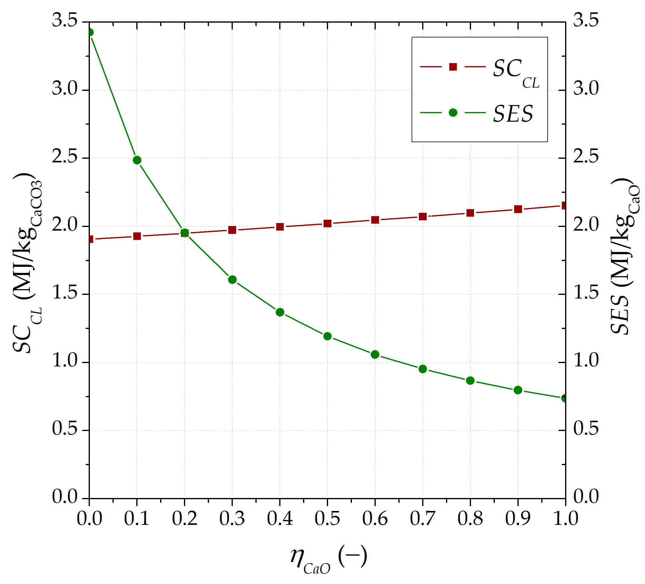
4.2. Specific Thermal Energy Demand and Storage

The specific thermal energy variables for consumption and storage were calculated using Equations (9) and (10), respectively, shown in Figure 4 as a function of η CaO . Both parameters assume the most advantageous value when the circulation between the reactors of the less carbonated material is zero, with the lowest energy demand (1.9 MJ/kg CaCO3) and the highest energy storage (3.4 MJ/kg CaO).
In more detail, for SCCL, the lower the inert solid input into the calciner, the greater the amount of carbonated material to be calcined. For SES, its highest value was almost 5 times the value obtained when no separation ( η CaO = 1 ) is considered (0.7 MJ/kg CaO). On the other hand, the influence of a higher carbonated material ratio ( η CaCO 3 ) on both variables ( SC CL   and SES) was minimal, reaching a defined value within all ranges of the lower carbonated material ratio (i.e., SC CL = 2 MJ/kg CaCO3 and SES = 1.1 MJ/kg CaO under η CaO of 0.5 and η CaCO 3 from 0 to 1).

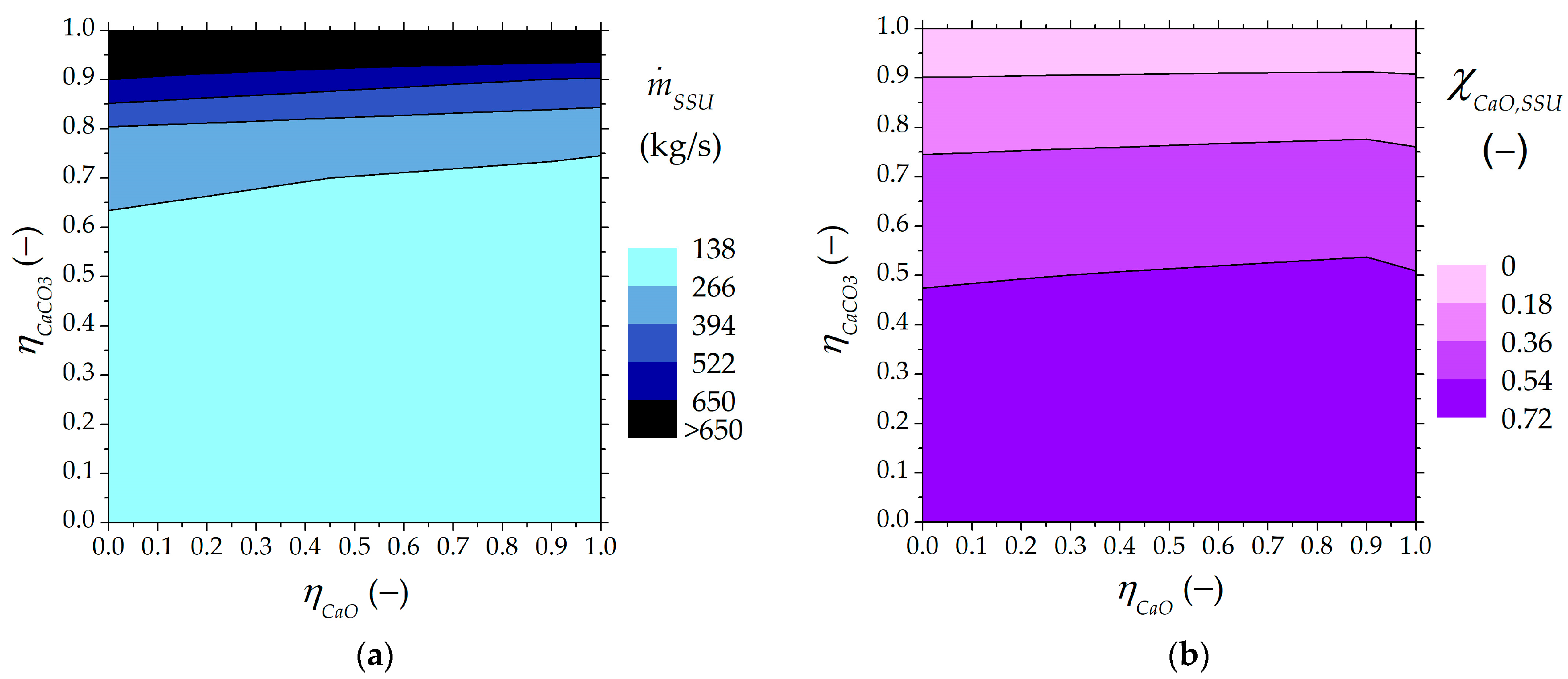
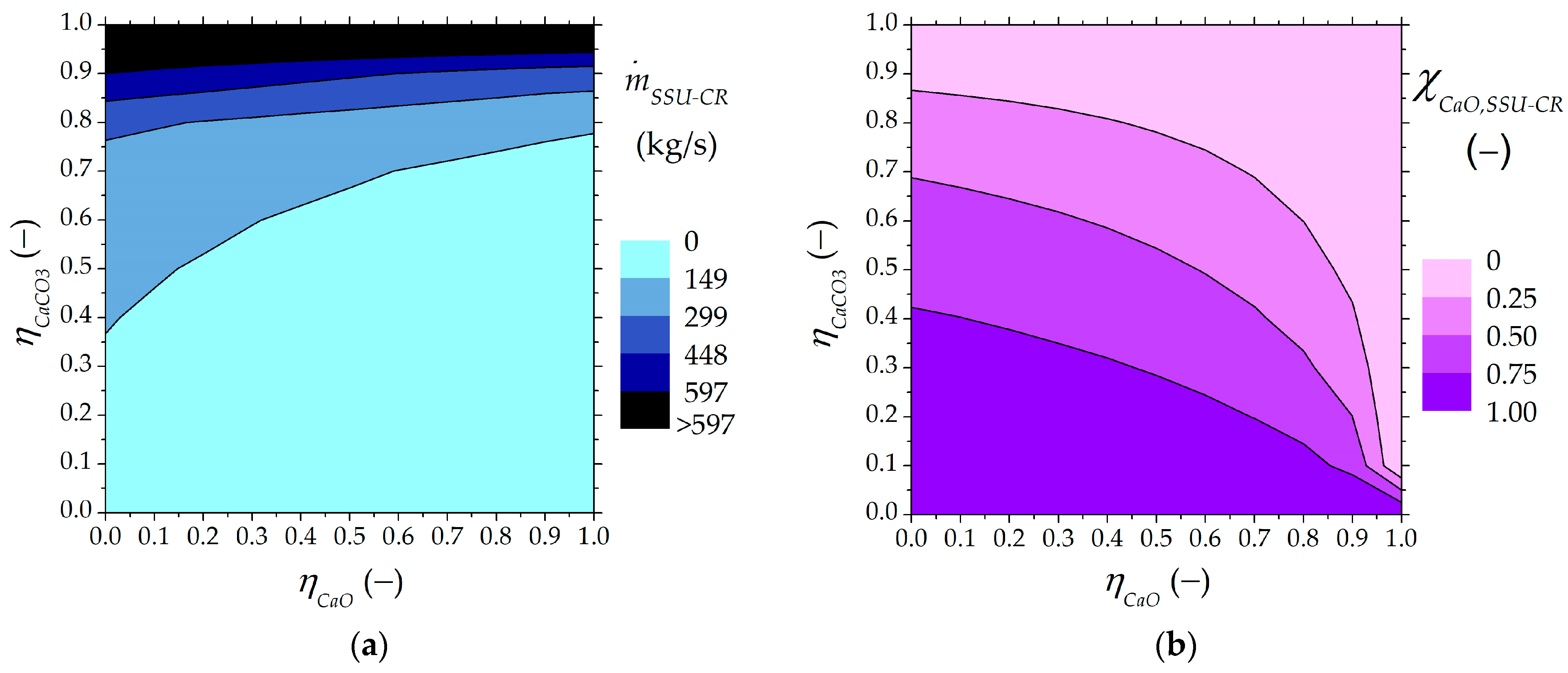
4.3. Nominal Streams to/from SSU

The input solid to the SSU and both output streams to the calciner and carbonator were assessed under nominal conditions. Moreover, the mass fraction of unreacted CaO for each inlet and outlet stream in the SSU was determined. The solid management in the SSU affected the circulation of the inert material in the system and, therefore, the plant size.
The solid input into the SSU from the carbonator and its content of carbonated material are shown in Figure 5. When the classification effectiveness reached 100% ( η CaCO 3 = η CaO = 0), the mass flow fed into the SSU from the carbonator was 171.1 kg/s, and this stream was rich in unreacted material ( χ CaO , SSU = 0.69). However, under a lower classification effectiveness of 25% ( η CaCO 3 = η CaO = 0.5), the solid input into the SSU could increase up to 201.8 kg/s with an unreacted material content ( χ CaO , SSU ) of 55%. The SSU input stream (Figure 5a) increased when the recirculation of more carbonated material into the carbonator rose, and less unreacted material was found in the carbonator outlet (Figure 5b). The technical and design feasibility of the SSU could be compromised for high values of the higher carbonated material ratio ( η CaCO 3 ). Moreover, the larger the presence of less carbonated material in the SSU feed flow rate ( χ CaO , SSU ), the higher the separation effectiveness.
The values for the solid stream recirculated into the carbonator are illustrated in Figure 6. The smaller the carbonated material flow rate that is recirculated into the carbonator, the larger the avoided unreacted CaO material circulating between the reactors.
The evolution of the solid stream leaving the SSU directed to the calciner or the ST1 storage tank is shown in Figure 7. The higher the carbonated material ratio ( η CaO ), the larger the amount of inert material circulating in the system ( χ CaO , SSU - CL ). The mass flow rate fed into the calciner increased from 53 to 144 kg/s, with a content of 0 to 72% in the unreacted material, raising the inert solids in the circulation. The higher the amount of inert material fed into the calciner, the greater the energy requirements to preheat the solids. Moreover, the SC CL was 13% higher when no separation of carbonated material takes place, compared to an operation with 100% recirculation of inert material into the carbonator.

4.4. Nominal Size of the Plant Equipment

The heat recovery from the carbonator and the size of two of the heat exchangers affected by the solid streams were determined under different separation points and nominal scenarios.
Figure 8 shows the nominal size of the carbonator influenced by the partial carbonated material separation. The lower the circulation of carbonated material between the reactors, the higher the heat released by the carbonator with the same nominal input of solar energy in the calciner (100 MW).
The size evolution of the heat exchangers next to the SSU and affected by the solid streams are also illustrated in Figure 8. The HE2 heat exchanger was located before the ST1 storage tank to cool the solid stream from the SSU. The maximum size could be achieved when no solid feed was required for the calciner. The greater the amount of carbonated material led to the ST1 storage tank, the larger the size required for HE2. The HE7 heat exchanger was situated before the carbonator to preheat the solid input stream. The maximum requirements were achieved when HE7 only received solid streams from the ST2 storage tank and the SSU. The lower the amount of carbonated material circulating between the reactors led to a smaller size required for HE7.
Therefore, potential partial separation may be feasible when solid management between reactors diminishes. The lower the circulation of unreacted material in the system and the lower the recirculation of more carbonated material into the carbonator, the better the classification effectiveness of the SSU and the specific energy storage. Moreover, the specific calciner consumption and plant size affected by the solid streams could be minimized, enhancing the retrieved energy from the carbonator.

5. Conclusions

A wide assessment of the energy and size requirements of a CaL TCES system was addressed. A suitable magnitude range of the CaL-based storage system was obtained under potential partial separation effectiveness after a carbonation reaction. The potential partial separation between less and more carbonated material was assessed given the potential energy and size savings achieved under a simulation. The future development of a solid–solid classifier after the carbonation step by the density difference started with the present research work. The energy and size requirements of the CaL TCES system were obtained under several operating points, combining different potential separations between less and more carbonated material. It was observed that the higher the recirculation of unreacted material into the carbonator (low ηCaO), the lower (i) the specific thermal energy consumption at calciner (SCCL) and (ii) the intermediate plant equipment size affected by solid streams (i.e., HE2, HE7). When there was no circulation of inert material in the CaL TCES system, the specific consumption in the calciner decreased by 12% to 1.9 MJ/kg CaCO3, and the size of the heat exchangers diminished up to 56 and 76% for HE2 and HE7, respectively. The retrieved energy from the carbonator and the specific energy storage increased when the circulation of inert material between the reactors diminished (low η CaO ). The nominal size of the carbonator rose to 32% for a classification effectiveness of 100%, which means that more heat was released for the same solar input in the calciner. The specific energy storage reached its maximum value (3.4 MJ/kg CaO) when the inert material cycled back to the carbonator. Moreover, a lower circulation of solids could be reached under higher classification effectiveness, minimizing the energy and size demands of the CaL TCES system. Both ratios defined to assess the potential operation points under partial separation of carbonated material affect the design of the CaL TCES system. The lower the carbonated material ratio ( η CaO ), the lower the circulation of the inert material between the reactors and the greater the energy and size savings of the CaL TCES system. The greater the carbonated material ratio ( η CaCO 3 ), the more compromised the technical feasibility of the SSU given the increase in the solid feed.
The present work serves as a direct tool for CaL TCES plant design under the potential partial separation of carbonated material. Further work must focus on the experimental assessment of carbonated particle segregation. The proper development and design of a solid–solid classifier via density difference could be achieved via an experimental test to predict the classification effectiveness, which is influenced by physical factors of the particles to be separated (i.e., granulometry (size and diameter), density, and minimum fluidization velocity).

Author Contributions

Conceptualization, S.P., L.M.R., P.L., R.S. and F.M.; methodology, S.P.; software, S.P.; formal analysis, S.P., P.L. and L.M.R.; investigation, C.T., F.D.L., R.S., P.S., F.M., P.L. and L.M.R.; resources, C.T., R.S., P.S., F.M., P.L. and L.M.R.; data curation, S.P.; writing—original draft preparation, S.P.; writing—review and editing, C.T., F.D.L., R.S., P.S., F.M., P.L. and L.M.R.; visualization, S.P., P.L. and L.M.R.; supervision, F.M., R.S., P.L. and L.M.R. All authors have read and agreed to the published version of the manuscript.

Funding

This research was funded by the Ministerio de Ciencia, Innovación y Universidades, FPU Programme grant number FPU 2017/03902 and FPU mobility grant number EST19/00144. This research was also funded by the Horizon 2020 Framework Programme (GA No. 727348, SOCRATCES project) and Gobierno de Aragón (Research Group DGA 959 T46_20R).

Data Availability Statement

Data is contained within the article.

Conflicts of Interest

The authors declare no conflicts of interest.

Nomenclature

Symbols
EGlobal classification effectiveness, -
E CaCO 3 Jetsam classification effectiveness, -
E CaO Fotsam classification effectiveness, -
fFraction, -
kModel constant, -
m ˙ Mass flow rate, mass/time
n ˙ Mole flow rate, moles/time
NNumber of carbonation/calcination cycles, -
Q ˙ Heat power, energy/time
rAge distribution of sorbent population, -
RMolar ratio CaO/CO2 at carbonator inlet, -
SCSpecific thermal energy consumption, energy/mass
SESSpecific energy storage, energy/mass
SHSensible heat, energy/time
XCaO carbonation degree, -
H R 0 Enthalpy of calcination/carbonation, energy/moles
η CaCO 3 More carbonated material ratio, -
η CaO Less carbonated material ratio, -
η capt Carbon capture efficiency, -
χMass fraction, -
Subscripts and superscripts
1Initial sorbent conversion
2Activity decay
aveAverage
CRCarbonator
CLCalciner
NNumber of carbonation/calcination cycles
pPurge
prePreheating
stStorage
SSUSolid–solid separation unit
Acronyms and abbreviations
CaLCalcium Looping
CCTCompressor and cooling train
CSPConcentrating solar power
DEDischarging expansion
EESEngineering equation solver
HEHeat exchanger
IADInitial activity decay
PVPhotovoltaic
SSUSolid–solid separation unit
STStorage tank
TCESThermochemical energy storage
TESThermal energy storage
TGAThermogravimetric analysis

References

  1. Shukla, P.R.; Skea, J.; Slade, R.; Al Khourdajie, A.; van Diemen, R.; McCollum, D.; Pathak, M.; Some, S.; Vyas, P.; Fradera, R. (Eds.) IPCC, 2022: Climate Change 2022: Mitigation of Climate Change. Contribution of Working Group III to the Sixth Assessment Report of the Intergovernmental Panel on Climate Change; Cambridge University Press: Cambridge, UK; New York, NY, USA, 2022. [Google Scholar]
  2. IEA. Net Zero by 2050: A Roadmap for the Global Energy Sector; International Energy Agency: Paris, France, 2021. [Google Scholar]
  3. REN21. Renewables 2023 Global Status Report—Energy Supply Collection; REN21: Paris, France, 2023; ISBN 978-3-948393-08-3. [Google Scholar]
  4. IEA. World Energy Outlook 2022; Technical Report; International Energy Agency: Paris, France, 2022; ISBN 0872625710. [Google Scholar]
  5. Goyal, N.; Aggarwal, A.; Kumar, A. Concentrated solar power plants: A critical review of regional dynamics and operational parameters. Energy Res. Soc. Sci. 2022, 83, 102331. [Google Scholar] [CrossRef]
  6. EC. Commission Staff Working Document: Energy Storage—The Role of Electricity; European Commission: Brussels, Belgium, 2017. [Google Scholar]
  7. EC. Report from the Commision to the European Parliament, the European Council, the Council, the European Economic and Social Committee and the Committee of the Regions. The European Green Deal; European Commission: Brussels, Belgium, 2019. [Google Scholar]
  8. Islam, T.; Huda, N.; Abdullah, A.B.; Saidur, R. A comprehensive review of state-of-the-art concentrating solar power (CSP) technologies: Current status and research trends. Renew. Sustain. Energy Rev. 2018, 91, 987–1018. [Google Scholar] [CrossRef]
  9. Kumar, A.; Shukla, S.K. A Review on Thermal Energy Storage Unit for Solar Thermal Power Plant Application. Energy Procedia 2015, 74, 462–469. [Google Scholar] [CrossRef]
  10. González-Roubaud, E.; Pérez-Osorio, D.; Prieto, C. Review of commercial thermal energy storage in concentrated solar power plants: Steam vs. molten salts. Renew. Sustain. Energy Rev. 2017, 80, 133–148. [Google Scholar] [CrossRef]
  11. Mohammad, A.; Khoshbaf, J.; Groningen, H.; Orozco, C. Thermal Energy Storage in CSP Technologies: From Commercialized to Innovative Solutions; French National Centre for Scientific Research: Paris, France, 2018. [Google Scholar]
  12. Xu, B.; Li, P.; Chan, C. Application of phase change materials for thermal energy storage in concentrated solar thermal power plants: A review to recent developments. Appl. Energy 2015, 160, 286–307. [Google Scholar] [CrossRef]
  13. Arias, I.; Cardemil, J.; Zarza, E.; Valenzuela, L.; Escobar, R. Latest developments, assessments and research trends for next generation of concentrated solar power plants using liquid heat transfer fluids. Renew. Sustain. Energy Rev. 2022, 168, 112844. [Google Scholar] [CrossRef]
  14. Achkari, O.; El Fadar, A. Latest developments on TES and CSP technologies—Energy and environmental issues, applications and research trends. Appl. Therm. Eng. 2020, 167, 114806. [Google Scholar] [CrossRef]
  15. Prieto, C.; Cooper, P.; Fernández, A.I.; Cabeza, L.F. Review of technology: Thermochemical energy storage for concentrated solar power plants. Renew. Sustain. Energy Rev. 2016, 60, 909–929. [Google Scholar] [CrossRef]
  16. Khan, M.I.; Asfand, F.; Al-Ghamdi, S.G. Progress in research and technological advancements of thermal energy storage systems for concentrated solar power. J. Energy Storage 2022, 55, 105860. [Google Scholar] [CrossRef]
  17. Coppola, A.; Senneca, O.; Scala, F.; Montagnaro, F.; Salatino, P. Looping cycles for low carbon technologies: A survey of recent research activities in Naples. Fuel 2020, 268, 117371. [Google Scholar] [CrossRef]
  18. Tregambi, C.; Bareschino, P.; Hanak, D.; Montagnaro, F.; Pepe, F.; Mancusi, E. Modelling of an integrated process for atmospheric carbon dioxide capture and methanation. J. Clean. Prod. 2022, 356, 131827. [Google Scholar] [CrossRef]
  19. Haaf, M.; Anantharaman, R.; Roussanaly, S.; Ströhle, J.; Epple, B. CO2 capture from waste-to-energy plants: Techno-economic assessment of novel integration concepts of calcium looping technology. Resour. Conserv. Recycl. 2020, 162, 104973. [Google Scholar] [CrossRef]
  20. Diego, M.E.; Alonso, M. Operational feasibility of biomass combustion with in situ CO2 capture by CaO during 360 h in a 300 kWth calcium looping facility. Fuel 2016, 181, 325–329. [Google Scholar] [CrossRef]
  21. SOCRATCES (SOlar Calcium-Looping integRAtion for ThermoChemical Energy Storage). Available online: https://socratces.eu/ (accessed on 6 October 2023).
  22. CALyPSOL (CALcium Oxide LooPing through SOLar Energy). Available online: https://www.dlr.de/ff/en/desktopdefault.aspx/tabid-18130/28811_read-71705/ (accessed on 6 October 2023).
  23. Grasa, G.S.; Abanades, J.C. CO2 Capture Capacity of CaO in Long Series of Carbonation/Calcination Cycles. Ind. Eng. Chem. Res. 2006, 45, 8846–8851. [Google Scholar] [CrossRef]
  24. Perejón, A.; Romeo, L.M.; Lara, Y.; Lisbona, P.; Martínez, A.; Valverde, J.M. The Calcium-Looping technology for CO2 capture: On the important roles of energy integration and sorbent behavior. Appl. Energy 2016, 162, 787–807. [Google Scholar] [CrossRef]
  25. Ortiz, C.; Valverde, J.M.; Chacartegui, R.; Perez-Maqueda, L.A. Carbonation of Limestone Derived CaO for Thermochemical Energy Storage: From Kinetics to Process Integration in Concentrating Solar Plants. ACS Sustain. Chem. Eng. 2018, 6, 6404–6417. [Google Scholar] [CrossRef]
  26. Tesio, U.; Guelpa, E.; Verda, V. Comparison of sCO2 and He Brayton cycles integration in a Calcium-Looping for Concentrated Solar Power. Energy 2022, 247, 123467. [Google Scholar] [CrossRef]
  27. Chen, X.; Zhang, Z.; Qi, C.; Ling, X.; Peng, H. State of the art on the high-temperature thermochemical energy storage systems. Energy Convers. Manag. 2018, 177, 792–815. [Google Scholar] [CrossRef]
  28. Khosa, A.A.; Xu, T.; Xia, B.Q.; Yan, J.; Zhao, C.Y. Technological challenges and industrial applications of CaCO3/CaO based thermal energy storage system—A review. Sol. Energy 2019, 193, 618–636. [Google Scholar] [CrossRef]
  29. Sarbu, I.; Sebarchievici, C. A Comprehensive Review of Thermal Energy Storage. Sustainability 2018, 10, 191. [Google Scholar] [CrossRef]
  30. Liu, D.; Long, X.-F.; Bo, L.; Zhou, S.-Q.; Xu, Y. Progress in thermochemical energy storage for concentrated solar power: A review. Int. J. Energy Res. 2018, 42, 4546–4561. [Google Scholar] [CrossRef]
  31. Alva, G.; Lin, Y.; Fang, G. An overview of thermal energy storage systems. Energy 2018, 144, 341–378. [Google Scholar] [CrossRef]
  32. Benitez-Guerrero, M.; Sarrion, B.; Perejon, A.; Sanchez-Jimenez, P.E.; Perez-Maqueda, L.A.; Manuel, J. Large-scale high-temperature solar energy storage using natural minerals. Sol. Energy Mater. Sol. Cells 2017, 168, 14–21. [Google Scholar] [CrossRef]
  33. Benitez-Guerrero, M.; Manuel, J.; Sanchez-Jimenez, P.E.; Perejon, A.; Perez-Maqueda, L.A. Multicycle activity of natural CaCO3 minerals for thermochemical energy storage in Concentrated Solar Power plants. Sol. Energy 2017, 153, 188–199. [Google Scholar] [CrossRef]
  34. Valverde, J.M.; Barea-López, M.; Perejón, A.; Sánchez-Jiménez, P.E.; Pérez-Maqueda, L.A. Effect of Thermal Pretreatment and Nanosilica Addition on Limestone Performance at Calcium-Looping Conditions for Thermochemical Energy Storage of Concentrated Solar Power. Energy Fuels 2017, 31, 4226–4236. [Google Scholar] [CrossRef]
  35. Arcenegui-Troya, J.; Sánchez-Jiménez, P.E.; Perejón, A.; Moreno, V.; Valverde, J.M.; Pérez-Maqueda, L.A. Kinetics and cyclability of limestone (CaCO3) in presence of steam during calcination in the CaL scheme for thermochemical energy storage. Chem. Eng. J. 2021, 417, 129194. [Google Scholar] [CrossRef]
  36. Arcenegui-Troya, J.; Sánchez-Jiménez, P.E.; Perejón, A.; Valverde, J.M.; Pérez-Maqueda, L.A. Steam-enhanced calcium-looping performance of limestone for thermochemical energy storage: The role of particle size. J. Energy Storage 2022, 51, 104305. [Google Scholar] [CrossRef]
  37. Sarrión, B.; Perejón, A.; Sánchez-Jiménez, P.E.; Pérez-Maqueda, L.A.; Valverde, J.M. Role of calcium looping conditions on the performance of natural and synthetic Ca-based materials for energy storage. J. CO2 Util. 2018, 28, 374–384. [Google Scholar] [CrossRef]
  38. Zheng, H.; Liu, X.; Xuan, Y.; Song, C.; Liu, D.; Zhu, Q.; Zhu, Z.; Gao, K.; Li, Y.; Ding, Y. Thermochemical heat storage performances of fluidized black CaCO3 pellets under direct concentrated solar irradiation. Renew. Energy 2021, 178, 1353–1369. [Google Scholar] [CrossRef]
  39. Da, Y.; Xuan, Y.; Teng, L.; Zhang, K.; Liu, X.; Ding, Y. Calcium-based composites for direct solar-thermal conversion and thermochemical energy storage. Chem. Eng. J. 2020, 382, 122815. [Google Scholar] [CrossRef]
  40. André, L.; Abanades, S. Evaluation and performances comparison of calcium, strontium and barium carbonates during calcination/carbonation reactions for solar thermochemical energy storage. J. Energy Storage 2017, 13, 193–205. [Google Scholar] [CrossRef]
  41. Ortiz, C.; Carro, A.; Chacartegui, R.; Valverde, J.M. Low-pressure calcination to enhance the calcium looping process for thermochemical energy storage. J. Clean. Prod. 2022, 363, 132295. [Google Scholar] [CrossRef]
  42. Valverde, J.M.; Sanchez-Jimenez, P.E.; Perejon, A.; Perez-Maqueda, L.A. Role of looping-calcination conditions on self-reactivation of thermally pretreated CO2 sorbents based on CaO. Energy Fuels 2013, 27, 3373–3384. [Google Scholar] [CrossRef]
  43. Valverde, J.M. A model on the CaO multicyclic conversion in the Ca-looping process. Chem. Eng. J. 2013, 228, 1195–1206. [Google Scholar] [CrossRef]
  44. Atkinson, K.; Hughes, R.; Macchi, A. Application of the Calcium Looping Process for Thermochemical Storage of Variable Energy. Energies 2023, 16, 3299. [Google Scholar] [CrossRef]
  45. Tregambi, C.; Di Lauro, F.; Pascual, S.; Lisbona, P.; Romeo, L.M.; Solimene, R.; Salatino, P.; Montagnaro, F. Solar-driven calcium looping in fluidized beds for thermochemical energy storage. Chem. Eng. J. 2023, 466, 142708. [Google Scholar] [CrossRef]
  46. Bravo, R.; Ortiz, C.; Chacartegui, R.; Friedrich, D. Hybrid solar power plant with thermochemical energy storage: A multi-objective operational optimisation. Energy Convers. Manag. 2020, 205, 112421. [Google Scholar] [CrossRef]
  47. Bravo, R.; Ortiz, C.; Chacartegui, R.; Friedrich, D. Multi-objective optimisation and guidelines for the design of dispatchable hybrid solar power plants with thermochemical energy storage. Appl. Energy 2021, 282, 116257. [Google Scholar] [CrossRef]
  48. Ortiz, C.; Chacartegui, R.; Valverde, J.M.; Carro, A.; Tejada, C.; Valverde, J. Increasing the solar share in combined cycles through thermochemical energy storage. Energy Convers. Manag. 2021, 229, 113730. [Google Scholar] [CrossRef]
  49. Ortiz, C.; Tejada, C.; Chacartegui, R.; Bravo, R.; Carro, A.; Valverde, J.M.; Valverde, J. Solar combined cycle with high-temperature thermochemical energy storage. Energy Convers. Manag. 2021, 241, 114274. [Google Scholar] [CrossRef]
  50. Tregambi, C.; Bareschino, P.; Mancusi, E.; Pepe, F.; Montagnaro, F.; Solimene, R.; Salatino, P. Modelling of a concentrated solar power—Photovoltaics hybrid plant for carbon dioxide capture and utilization via calcium looping and methanation. Energy Convers. Manag. 2021, 230, 113792. [Google Scholar] [CrossRef]
  51. Pascual, S.; Romeo, L.M.; Lisbona, P. Optimized Ca-looping thermochemical energy storage under dynamic operation for concentrated solar power. J. Energy Storage 2023, 68, 107587. [Google Scholar] [CrossRef]
  52. Martinez Castilla, G.; Guío-Pérez, D.C.; Papadokonstantakis, S.; Pallarès, D.; Johnsson, F. Techno-Economic Assessment of Calcium Looping for Thermochemical Techno-Economic Assessment of Calcium Looping for Thermochemical Energy Storage with CO2 Capture. Energies 2021, 14, 3211. [Google Scholar] [CrossRef]
  53. Di Lauro, F.; Tregambi, C.; Montagnaro, F.; Molignano, L.; Salatino, P.; Solimene, R. Influence of Fluidised Bed Inventory on the Performance of Limestone Sorbent in Calcium Looping for Thermochemical Energy Storage. Energies 2023, 16, 6942. [Google Scholar] [CrossRef]
  54. Ortiz, C.; Valverde, J.M.; Chacartegui, R.; Perez-Maqueda, L.A.; Giménez, P. The Calcium-Looping (CaCO3/CaO) process for thermochemical energy storage in Concentrating Solar Power plants. Renew. Sustain. Energy Rev. 2019, 113, 109252. [Google Scholar] [CrossRef]
  55. Pascual, S.; Lisbona, P.; Bailera, M.; Romeo, L.M. Design and operational performance maps of calcium looping thermochemical energy storage for concentrating solar power plants. Energy 2021, 220, 119715. [Google Scholar] [CrossRef]
  56. Pascual, S.; Lisbona, P.; Romeo, L.M. Operation maps in calcium looping thermochemical energy storage for concentrating solar power plants. J. Energy Storage 2022, 55, 105771. [Google Scholar] [CrossRef]
  57. Tregambi, C.; Di Lauro, F.; Montagnaro, F.; Salatino, P.; Solimene, R. 110th anniversary: Calcium looping coupled with concentrated solar power for carbon capture and thermochemical energy storage. Ind. Eng. Chem. Res. 2019, 58, 21262–21272. [Google Scholar] [CrossRef]
  58. Chacartegui, R.; Alovisio, A.; Ortiz, C.; Valverde, J.M.; Verda, V.; Becerra, J.A. Thermochemical energy storage of concentrated solar power by integration of the calcium looping process and a CO2 power cycle. Appl. Energy 2016, 173, 589–605. [Google Scholar] [CrossRef]
  59. Abanades, J.C. The maximum capture efficiency of CO2 using a carbonation/calcination cycle of CaO/CaCO3. Chem. Eng. J. 2002, 90, 303–306. [Google Scholar] [CrossRef]
  60. Romeo, L.M.; Lara, Y.; Lisbona, P.; Escosa, J.M. Optimizing make-up flow in a CO2 capture system using CaO. Chem. Eng. J. 2009, 147, 252–258. [Google Scholar] [CrossRef]
  61. Olivieri, G.; Marzocchella, A.; Salatino, P. A fluid-bed continuous classifier of polydisperse granular solids. J. Taiwan Inst. Chem. Eng. 2009, 40, 638–644. [Google Scholar] [CrossRef]
Figure 1. CaL TCES scheme under the partial separation of carbonated solids scenario.
Energies 17 01372 g001
Figure 2. Sensitivity assessment of the effect of the spent CaO purge fraction (fp) under the total separation of the carbonated solids (reference base).
Energies 17 01372 g002
Figure 3. Global separation effectiveness (E) as a function of more and less carbonated material ratios.
Energies 17 01372 g003
Figure 4. Specific energy consumption in the calciner ( SC CL ) and specific energy storage (SES) under different ratios of inert solid material circulating in the CaL TCES system ( η CaO ).
Energies 17 01372 g004
Figure 5. Solid fed to the SSU from the carbonator as a function of higher and lower carbonated material ratios: (a) input flow rate to the SSU, (b) mass fraction of unreacted CaO in the SSU input stream.
Energies 17 01372 g005
Figure 6. Solids leaving the SSU directed to the carbonator as a function of higher and lower carbonated material ratios: (a) output flow rate from the SSU to the carbonator, (b) mass fraction of unreacted CaO in the SSU output stream recirculated into the carbonator.
Energies 17 01372 g006
Figure 7. Mass flow rate and unreacted CaO content of solids leaving the SSU directed to the calciner as a function of the lower carbonated material ratio.
Energies 17 01372 g007
Figure 8. Nominal size of the carbonator and heat exchangers affected by solid streams (HE2 and HE7), expressed in terms of thermal power under different lower carbonated material ratios ( η CaO ).
Energies 17 01372 g008
Disclaimer/Publisher’s Note: The statements, opinions and data contained in all publications are solely those of the individual author(s) and contributor(s) and not of MDPI and/or the editor(s). MDPI and/or the editor(s) disclaim responsibility for any injury to people or property resulting from any ideas, methods, instructions or products referred to in the content.

