Article

Common-Mode Voltage Reduction of Modular Multilevel Converter Using Adaptive High-Frequency Injection Method for Medium-Voltage Motor Drives

1
Electric Machines and Drives Research Center, Korea Electrotechnology Research Institute, Changwon-si 51543, Republic of Korea
2
School of Electrical Engineering, Pusan National University, Busan 46241, Republic of Korea
*
Authors to whom correspondence should be addressed.
Energies 2024, 17(6), 1367; https://doi.org/10.3390/en17061367
Submission received: 14 February 2024 / Revised: 3 March 2024 / Accepted: 8 March 2024 / Published: 12 March 2024
(This article belongs to the Section F3: Power Electronics)

Abstract

:
This study proposes an adaptive high-frequency injection method (AHFI) aimed at mitigating common-mode voltage (CMV) on the AC side and alleviating current stress on power semiconductor devices within each arm of a medium-voltage motor propulsion system designed for modular multilevel converters. By adjusting the quantity of high-frequency components injected into each arm according to the fluctuation coefficient, the amplitude of injected high-frequency CMV and circulating currents can be reduced across medium to rated motor speeds. This approach enhances the start-up performance of medium-voltage motor drives while diminishing CMV effects on the motor side, resulting in decreased total harmonic distortion (THD) in the three-phase output waveforms. Furthermore, the effectiveness of the proposed AHFI method in SM voltage regulation and circulating current control under low-frequency operation is thoroughly analyzed. The validity of this method is established through comprehensive mathematical scrutiny and time–domain simulations performed using MATLAB/SIMULINK software (MATLAB version R2021b), along with real-time simulations conducted employing the real-time simulator OPAL/RT via hardware-in-the-loop simulation (HILS).

1. Introduction

Modular multilevel converters (MMC) have emerged as a promising topology for medium- to high-voltage power conversion applications in recent years due to their advantages, including low output voltage distortion, modularity, and scalability [1,2]. As a result, MMCs have found extensive use in both academic and industrial settings, including applications such as high-voltage direct current (HVDC) systems [3,4,5,6], static synchronous compensators (STATCOMs) [7,8,9], and motor drives [10,11,12,13,14,15,16,17]. Besides the salient features, SM capacitors suffer from severe fundamental frequency voltage fluctuation during the low/zero speed operation of motor drives, requiring the capacity of the SM capacitors to be large enough to reduce the voltage fluctuation. Additionally, the applications of the MMC system can be limited because of the large number of floating SM capacitors in the MMC topology, which makes the converter system bulky and costly [18]. Theoretically, the peak-to-peak value of the SM voltage varies directly with the output current amplitude, and inversely with the operating frequency [19]. Consequently, minimizing SM voltage ripple becomes imperative to guaranteeing the high efficiency and reliability of the MMC system during low-speed operation, especially at the outset of motor drive operation.
To overcome this problem, various types of control strategies have been developed to mitigate SM voltage fluctuations under standstill/low-speed operation of the motor drive system. In [19], the injection of high-frequency common-mode voltage (CMV) and circulating current into each converter phase was first proposed to suppress the energy imbalance between the upper and lower arms, resulting in a reduction in the SM capacitor voltage fluctuation during the start-up duration of the motor drives. Owing to the injection of high-frequency components, CMV is imposed on the AC side of the motor, which can damage the motor bearings and degrade the motor winding insulation [13]. In addition, with the increase in motor speed, the circulating current increases because of the increase in the injected high-frequency current, resulting in higher current stress and power loss in semiconductor devices.
Therefore, the problems of reducing the current stress and CMV imposed on the motor side should be considered to ensure high performance of the MMC system. By injecting high-frequency square-wave waveforms of CMV and circulating current instead of sinusoidal waveforms, the peak-to-peak value of the circulating current can be reduced significantly [11]. However, square-waveform CMV may pose significant challenges in terms of dv/dt at the motor terminal, which can jeopardize the longevity of motor bearings and render them unsuitable for practical applications [20,21]. To address these concerns, numerous investigations have been undertaken to guarantee the dependability and optimal functionality of converter systems across the complete spectrum of motor drive speeds [13,14,15]. In [13], an improved circulating current injection method was presented to operate an MMC system for controlling motor drives during the entire speed operation. Although this study is effective in reducing the SM voltage fluctuation and circulating current, the effectiveness of the method is evaluated using RL load under low-speed operation only. Similarly, a coordinated control strategy, which combines the circulating current injection method [14] considering the average SM voltage reduction, is presented for standstill/low-speed operation [15]. However, the capacitor can be damaged when its voltage exceeds the withstand value.
This study proposes an adaptive high-frequency injection (AHFI) scheme to improve the performance of the MMC system under standstill/low-speed operation of the motor drive, while reducing the CMV on the motor side using an adaptive high-frequency injection method. By determining the number of high-frequency components injected into each arm using the fluctuation coefficient (α), which dynamically adjusts based on the motor speed, we can significantly reduce CMV and arm current stress under medium to rated speed conditions of the motor drive system. This dynamic adjustment mechanism, a novel contribution of our study, allows for precise modulation of high-frequency components, ensuring optimal system performance across a wide range of operational states.
The main contributions of this study are as follows:
  • Development and implementation of the AHFI method, in which the fluctuation coefficient (α) plays a crucial role in dynamically adjusting the injection of high-frequency components to optimize system performance and efficiency.
  • Design and application of a closed-loop controller tailored to the AHFI method, enhancing the MMC system’s adaptability and resilience to operational changes.
  • Comprehensive validation of the AHFI method’s effectiveness across the entire speed range of motor drives, demonstrating significant improvements in mitigating CMV and reducing arm current stress, particularly under low-speed conditions.
The manuscript is organized as follows: Section 2 delves into the analysis of SM capacitor voltage fluctuation during low-frequency operation, highlighting the impact of the fluctuation coefficient (α). Section 3 introduces the adaptive high-frequency injection approach, emphasizing its novel application in mitigating SM voltage fluctuations and reducing circulating current and CMV effects on the motor side through the strategic use of α. Validation of the proposed method is conducted through time–domain simulation results utilizing the real-time simulator OPAL/RT and MATLAB/SIMULINK, along with hardware-in-the-loop simulation (HILS). The principal contributions and concluding remarks of the study, including a detailed discussion on the significance of α in optimizing the AHFI method, are summarized in Section 6.

2. Modular Multilevel Converter: Circuit and Operation

2.1. Circuit and Operation of MMC

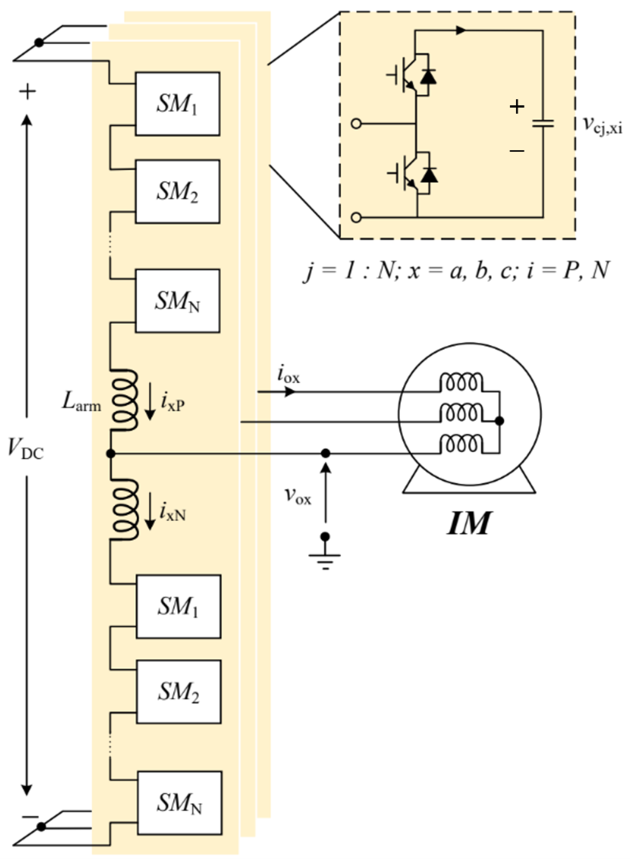
The circuit depicted in Figure 1 illustrates a three-phase MMC configuration integrated with an induction motor (IM). Each phase comprises two arms: the upper arm, which is connected to the positive bar; and the lower arm, which is connected to the negative bar. Within each arm, Nsm identical SMs serving to regulate currents circulating within the converter due to voltage disparities between the arms, are arranged in series with a buffer inductor (Larm). Each SM typically consists of a half-bridge (HB) power circuit comprising two power semiconductors, symbolized by IGBTs T1 and T2, along with an isolated capacitor (Cdc) and free-wheeling diodes.

2.2. Submodule Voltage Fluctuation Suppression during Low-Frequency Operation

v o x = V x c o s ( ω t + δ x ) i o x = I x c o s ( ω t + δ x ϕ x )
Here, x represents phases a, b, and c, while v o x denotes the output voltage and i o x represents the output current. V x and I x refer to the magnitudes of the output voltage and current of each phase, respectively, while δ x and ϕ x signify the phase angle of each phase and the phase difference between voltage and current, respectively.
To suppress the SM voltage fluctuation, high-frequency voltage ( v h ) and current ( i h ) are injected into each arm [19], as expressed in Equations (2) and (3), respectively.
v h = V h c o s ( ω h t )
i h = I h c o s ( ω h t )
The upper and lower arm voltages ( v x P and v x N ) considering the injected high-frequency voltage ( v h ) can be derived using Kirchhoff’s law voltage, as expressed in Equation (4).
ν x P = 1 2 V D C v o x v h v x N = 1 2 V D C + v o x + v h
VDC is the DC-link voltage, v x P and v x N are the upper and lower arm voltages of phase x.
In addition, the upper and lower arm currents of phase x (ixP and ixN) with the injection of a high-frequency current ( i h ) can be expressed as shown in Equation (5). It should be noted that the high frequency (fh) should be selected to be less than 10% of the switching frequency of the converter (fhfsw/10) to achieve good controllability [11].
i x P = 1 2 i o x + i c i r x , d c + i h i x N = 1 2 i o x + i c i r x , d c + i h
Here, icirx,dc represents the DC circulating current of phase x, while ixP denotes the upper arm current and ixN represents the lower arm current of phase x.
The upper and lower arm instantaneous powers (PxP, PxN) can be calculated using Equation (6) and derived from Equations (4) and (5) by multiplying the arm voltage and current, respectively.
P x P = 1 2 V D C v o x v h 1 2 i o x + i c i r x , d c + i h P x N = 1 2 V D C + v o x + v h 1 2 i o x + i c i r x , d c + i h
P x P = 1 4 V D C i o x + 1 2 V D C i h 1 2 v o x i o x     v o x i c i r x , d c v o x i h 1 2 v h i o x v h i c i r x , d c v h i h P x N = 1 4 V D C i o x + 1 2 V D C i c i r x , d c + 1 2 V D C i h 1 2 v o x i o x     + v o x i c i r x , d c + v o x i h 1 2 v h i o x + v h i c i r x , d c + v h i h
High-frequency components exert minimal influence on voltage ripple but demonstrate primary sensitivity to the fundamental frequency and second-order harmonics [23]. Therefore, this study disregards high-frequency elements and focuses solely on the fundamental frequency and second harmonic constituents (refer to Equation (8)). There is no clear contrast between the upper and lower arms concerning SM voltage fluctuation control. To simplify the analysis, attention is directed exclusively towards the power dynamics within the upper arm for mitigating SM voltage fluctuation.
P x P = 1 2 V D C i c i r x , d c 1 2 v o x i o x + 1 4 V D C i o x                                   v o x i c i r x , d c 1 2 V h I h P x N = 1 2 V D C i c i r x , d c 1 2 v o x i o x 1 4 V D C i o x                                   + v o x i c i r x , d c + 1 2 V h I h
Considering the ripple power of the upper arm as expressed in Equation (8), the first and second terms of Equation (8) are equal to each other due to the power balance between the DC and AC sides [24]. Therefore, i c i r x , d c can be obtained as follows.
i c i r x , d c = v o x i o x V D C
As mentioned earlier, the power fluctuations are mainly caused by the fundamental and second-order harmonic components, while the high-frequency components are ignored because of their small influence on the SM voltage fluctuation. By substituting Equation (9) into Equation (8), the upper arm power can be derived as expressed in Equation (10).
P x P = 1 4 V D C i o x 1 2 V h I h
To suppress the power arm ripple, the first term should be mitigated by the second term in Equation (10), which is injected into each arm at a very high frequency, as expressed in Equation (11).
1 2 V h I h = 1 4 V D C i o x
As a result, the SM voltage fluctuation is reduced by injecting high-frequency components (vh and ih) into each arm, thereby suppressing power fluctuations. However, the injection of these high-frequency components imposes CMV on the motor side and increases current stress on power semiconductor devices, consequently increasing system power loss.
In this study, the quantity of high-frequency components injected into each arm is determined using the fluctuation coefficient α, which varies according to motor speed variations. The primary concept of the proposed control strategy is to fully inject high-frequency components into each arm to mitigate SM voltage ripple in the low-speed range of the motor drive, and partially inject high-frequency components in the medium- and high-speed ranges to reduce CMV and current stress on power semiconductors. Detailed information about the proposed AHFI scheme is provided in the following section.

3. Proposed Adaptive High-Frequency Circulating Current Injection Method

3.1. Proposed Adaptive High-Frequency Injection Method for Reducing SM Voltage Fluctuation

By adaptively injecting the high-frequency components of the circulating current and CMV into each arm using the fluctuation coefficient α, the SM voltage fluctuation is suppressed under low-speed operation of the motor. In addition, the high-frequency components are removed from each arm, resulting in reduced current stress in the semiconductor devices and no CMV imposed on the AC side of the system during the motor’s medium- and high-speed operation. According to Equation (11), the first term is proportionally controlled by the second term using the coefficient α as expressed in Equation (12). In this study, the fluctuation coefficient (α) is controlled as a time variation coefficient ranging from zero to one (0 ≤ α ≤ 1).
1 2 V h I h = 1 4 α V D C i o x
where α is the fluctuation coefficient, which is used to determine the amount of injected high-frequency components, V h and I h are the amplitudes of the high-frequency voltage and current injected into each arm, respectively, determined by the fluctuation coefficient α.
The upper arm power can be derived as expressed in Equation (13) by substituting the output current in Equation (1) and the high-frequency components in Equation (12) into Equation (10).
P x P = 1 4 ( 1 α ) V D C I x c o s ( ω t + δ x ϕ x )
By integrating the upper arm power (PxP) in Equation (13), the energy fluctuation (Exp) can be obtained, as expressed in Equation (14).
E x P = 1 4 ω ( 1 α ) V D C I x s i n ( ω t + δ x ϕ x )
Likewise, the energy fluctuation in the lower arm can be calculated, as shown in Equation (15).
E x N = 1 4 ω ( 1 α ) V D C I x s i n ( ω t + δ x ϕ x )
The peak-to-peak energy variation (Ex,p-p) of phase x can be calculated by taking the difference between the maximum energy variation of the upper arm and that of the lower arm, as defined in Equation (16).
E x , p - p = 1 2 ω ( 1 α ) V D C I x
Based on the correlation between energy ripple and SM capacitor voltage ripple, the peak-to-peak SM voltage can be determined by substituting the peak-to-peak energy variation (Ex,p-p) from Equation (16) into Equation (17), yielding Equation (18).
E x , p - p = N s m C d c 2 ( v c , m a x 2 v c , m i n 2 ) = N s m C d c v c Δ v p - p
Δ v p - p = 1 α 2 I 0 ω C d c
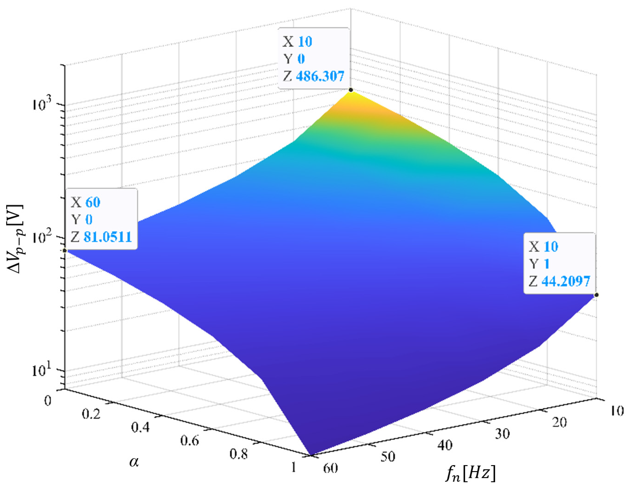
Figure 2 illustrates the variable operating frequency (fn) and fluctuation coefficient (α) dependence of SM voltage ripple’s maximum and minimum values (Δvp-p). During the low-frequency operation, the SM voltage fluctuates in a large range of 486 V without the injection of high-frequency components (α = 0), as illustrated in Figure 2 and mathematically demonstrated in Equation (18). By fully injecting the high-frequency component (α = 1), the SM voltage ripple is suppressed with a peak-to-peak voltage ripple of 44 V, as illustrated in Figure 2. In these cases, a minimum frequency of 10 Hz is considered for the finite value of peak-to-peak ripple, as demonstrated in Equation (18).
According to Equation (18), the fluctuation coefficient (α) can be derived as expressed in Equation (19).
α = 1 2 C d c Δ v p - p ω I 0
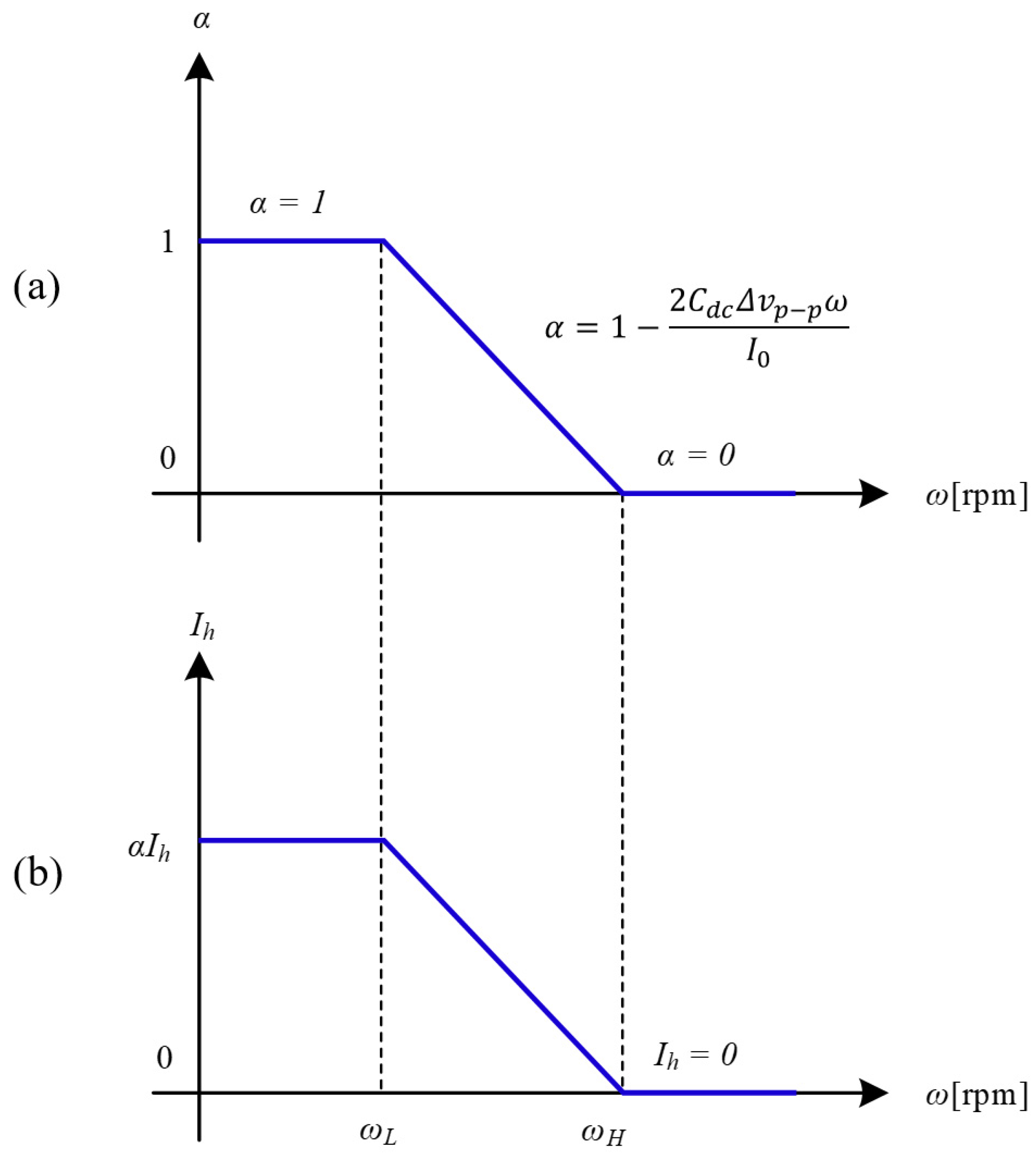
In this study, the fluctuation coefficient (α) is used to determine the operation of the MMC system based on the variation in the operating frequency. As expressed in Equation (19), during the start-up/standstill operation of the motor drives (ω = 0), the fluctuation coefficient is equal to one (α = 1) and gradually decreases when the operating frequency increases. Therefore, the high-limit frequency (ωH) is derived to determine the amount of high-frequency component injection, as expressed in Equation (20).
ω H = I 0 2 C d c Δ v p - p
Figure 3 illustrates the concept of the proposed method in determining the amount of injected high-frequency components using a fluctuation coefficient (α) ranging from zero to one, according to the variation in motor speed (ω). During the start-up/standstill operation of motor drives (ω < ωL), the SM capacitor suffers from high voltage fluctuations which can be eliminated by injecting 100% of the high-frequency circulating current and CMV into each arm with a fluctuation coefficient α = 1. In this study, ωL is selected to be approximately 1/3 of the rated frequency of 15 Hz. When the motor speed increases, the injected high-frequency circulating current and CMV gradually decreases, owing to the gradual decrease in the fluctuation coefficient α, as shown in Figure 3a. When ω > ωH, the high-frequency components are removed from the arm currents, and when ωL < ω < ωH, the amount of high-frequency components injected into each arm is determined using the fluctuation coefficient, as specified in Equation (19).

3.2. Balancing SM Voltage through an Adaptive High-Frequency Injection Approach

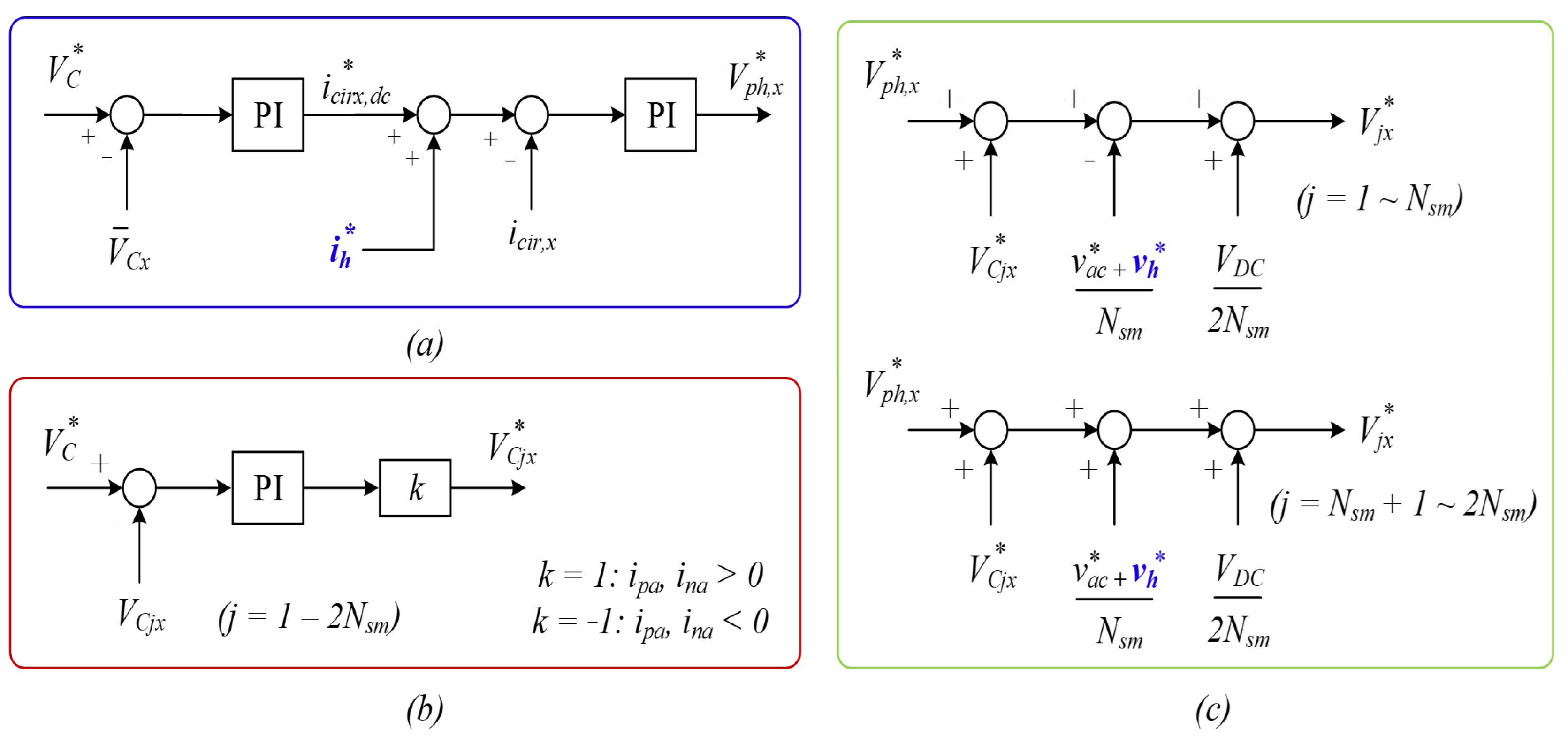
The schematic diagram in Figure 4 illustrates the application of the proposed adaptive high-frequency injection method for regulating SM voltage. This method involves phase voltage regulation, arm voltage regulation, and individual SM voltage control [11]. Equation (21) defines the average phase voltage ( V ¯ c x ), which is controlled to match the average voltage reference ( V ¯ c x ) using a proportional–integral (PI) controller, as depicted in Figure 4a. The output of the phase voltage controller ( i c i r c , d c ) serves as a reference for the circulating current controller. Additionally, the circulating current ( i c i r , x ) is adjusted to meet the circulating current reference by incorporating a high-frequency component ( i h ) that is determined by the fluctuation coefficient α.
V ¯ c x = 1 2 N s m j = 1 N s m ( V c j , x u + V c j , x l )
The average capacitor voltage across phase x is represented by V ¯ c x , while V c j , x u and V c j , x l correspond to the jth SM voltages of the upper and lower arms, respectively. N s m denotes the number of SMs per arm.
In Figure 4b, the diagram depicts individual control of SM voltages, with each SM voltage regulated to align with the voltage reference ( V C ). Furthermore, the polarity of the controller output ( V C j x ) for SM voltage reference generation is determined by the direction of the arm currents (ixP and ixN).
In Figure 4c, a schematic is presented detailing the integration of high-frequency CMV injection into each arm and the generation of SM voltage references. Equations (22) and (23) provide additional elucidation on this notion regarding the upper and lower arms.
V j x = V p h , x + V C j x v a c + v h N s m + V D C 2 N s m ( j = 1 : 4 )
V j x = V p h , x + V C j x + v a c + v h N s m + V D C 2 N s m ( j = 5 : 8 )

3.3. Overall Control Block Diagram of the MMC System Based on the Proposed AHFI

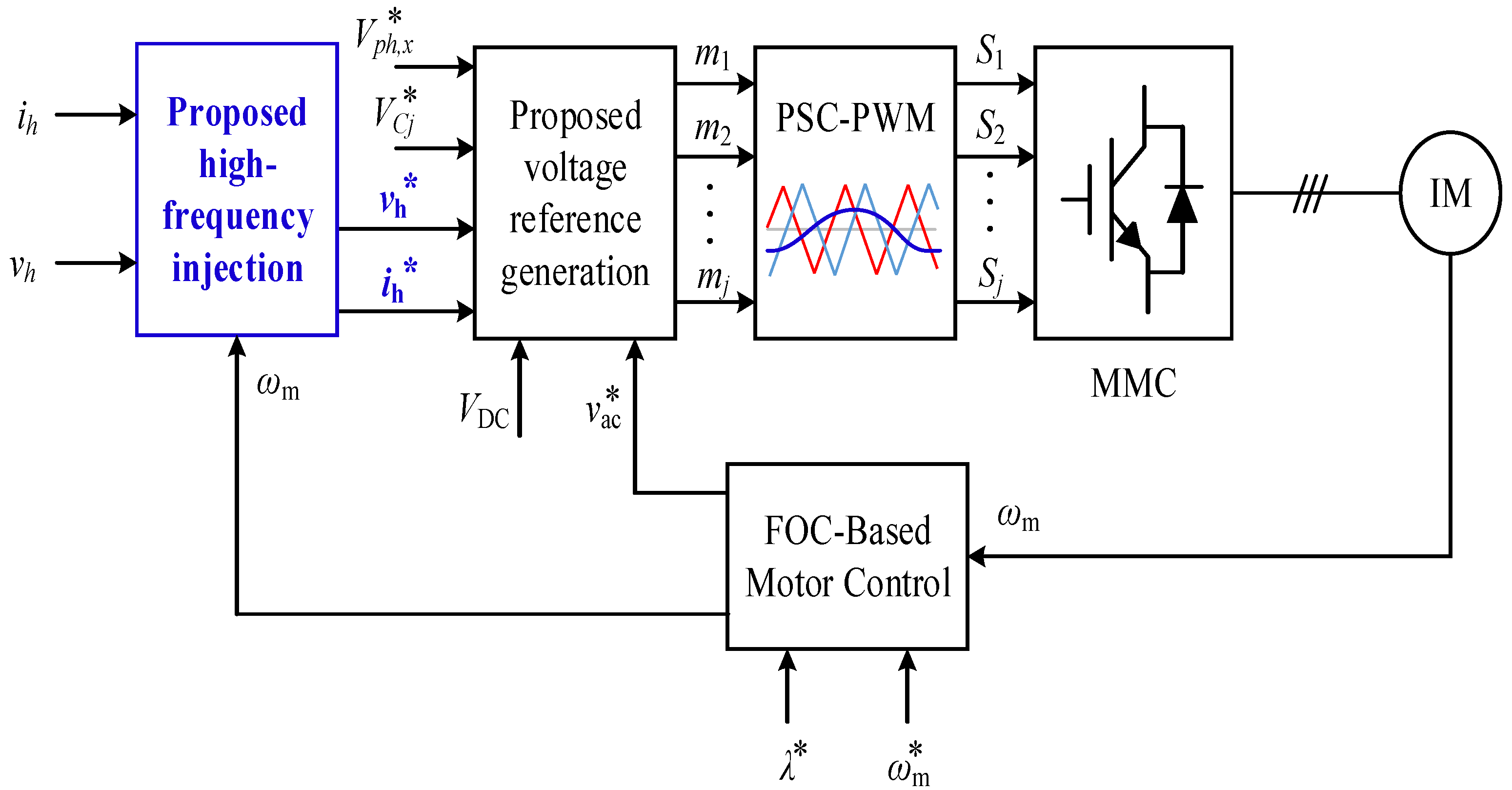
Figure 5 shows the closed-loop block diagram of the MMC system integrated with a motor drive based on the proposed AHFI method, which generates high-frequency voltage and current ( v h and i h ) for generating the SM voltage reference, as illustrated in Figure 4a,c. Additionally, the field-oriented control (FOC) is performed using the motor speed reference ( ω ), rotor flux reference ( λ ), and motor speed feedback (ɷ) to provide AC voltage reference ( v a c ) for SM voltage generation, as shown in Figure 4c and expressed in Equations (22) and (23). More comprehensive insights into FOC-based motor drives utilizing the d-q reference frame are available in reference [24].
By determining the amount of high-frequency voltage and current injected into each using the fluctuation coefficient (α), the SM voltage fluctuation can be reduced during the start-up operation, and the CMV imposed on the motor side can be significantly reduced during the medium- and high-speed operation of the motor drive. In this study, the fluctuation coefficient (α) is determined as a time variation coefficient according to the variation in motor speed, as illustrated in Figure 3. The output of the proposed AHFI block ( v h and i h ) is used to generate SM modulation signals, as illustrated in Figure 5. Furthermore, SM modulation signals can be generated with the assistance of phase voltage regulation, individual control of SM voltages, and management of circulating currents, as detailed in Section 3.2.

4. Simulation Results

In this section, the effectiveness of the proposed AHFI method for improving the start-up performance of the motor drives while reducing the CMV imposed on the motor side is verified using MATLAB/SIMULINK software. The motor converter system is composed of an IM and a three-phase MMC with four SMs per arm, making a total of 24 SMs. First, a start-up performance comparison between the conventional MMC [25] and the proposed AHFI is conducted using a time–domain simulation. Then, the performance of the proposed AHFI in reducing the CMV imposed on the motor side and arm current stress has been compared with the conventional high-frequency injection method using time–domain simulation [19].
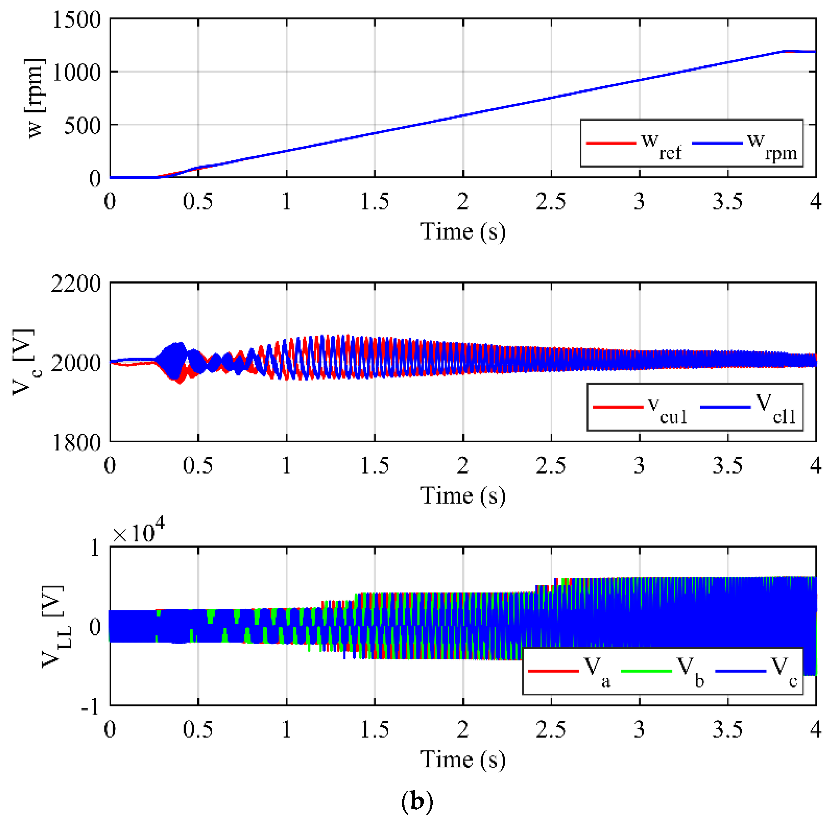
The system parameters are listed in Table 1. A performance comparison between the conventional MMC without high-frequency circulating current injection and the proposed AHFI method is shown in Figure 6. As shown in Figure 6a, without the proposed AHFI method, the SM voltage suffers from excessive fluctuation (>60%) during the start-up process, resulting in the distortion of the three-phase output line voltage. In contrast, with the proposed AHFI, the SM voltages are kept balanced with allowable voltage fluctuations (<10%), leading to the balance of the three-phase output voltage, as shown in Figure 6b.
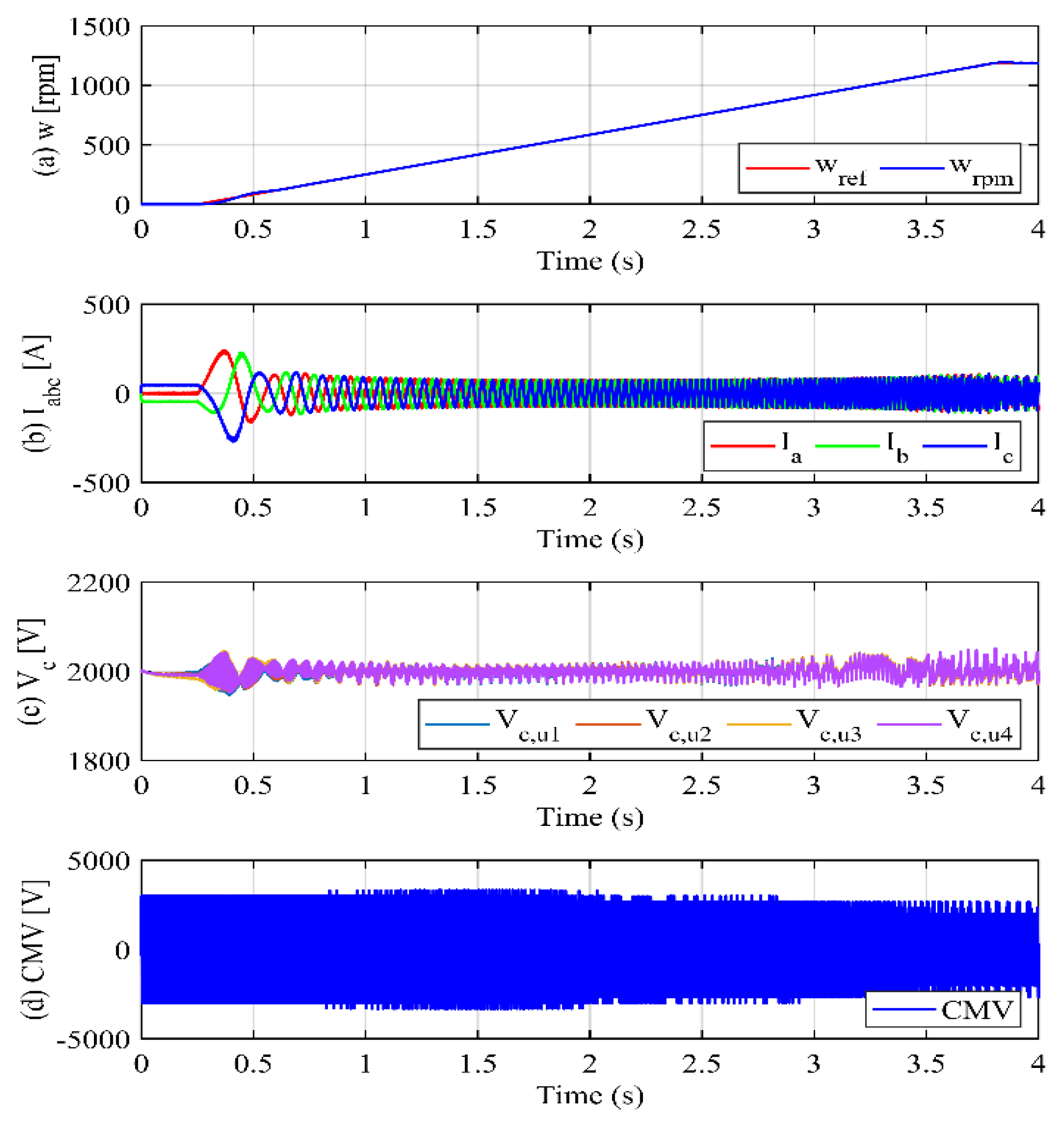
Figure 7 shows the time–domain simulation waveforms of the conventional high-frequency current injection method for driving a medium-voltage IM under no-load conditions. As shown in Figure 7a, the IM is accelerated from zero to the rated motor speed of 1189 rpm at the time instant of t = 0.25 s and the motor speed follows the motor speed reference (ωref) under the driving of the FOC control method. As soon as the motor speed changes, the MMC supplies rated three-phase current to the IM, as shown in Figure 7b.
In the acceleration process, the Submodule (SM) voltages within our Modular Multilevel Converter (MMC) system, designed to simulate an 8000 V DC link, are effectively balanced at a voltage of 2000 V per SM. This balance is maintained with the aid of high-frequency components injected into each arm, as depicted in Figure 7c. It is essential to note that our MMC configuration comprises 4 SMs per arm, leading to each SM experiencing a voltage of 2000 V, thus ensuring the balanced operation across the system.
However, this injection of high-frequency components introduces Common-Mode Voltage (CMV) on the motor side, which presents potential risks to motor winding insulation and bearings. As illustrated in Figure 7d, the CMV oscillates within ±3500 V, which is approximately half of the DC-link voltage. This phenomenon underscores the complexity of managing high-frequency components to mitigate adverse effects while maintaining system performance.
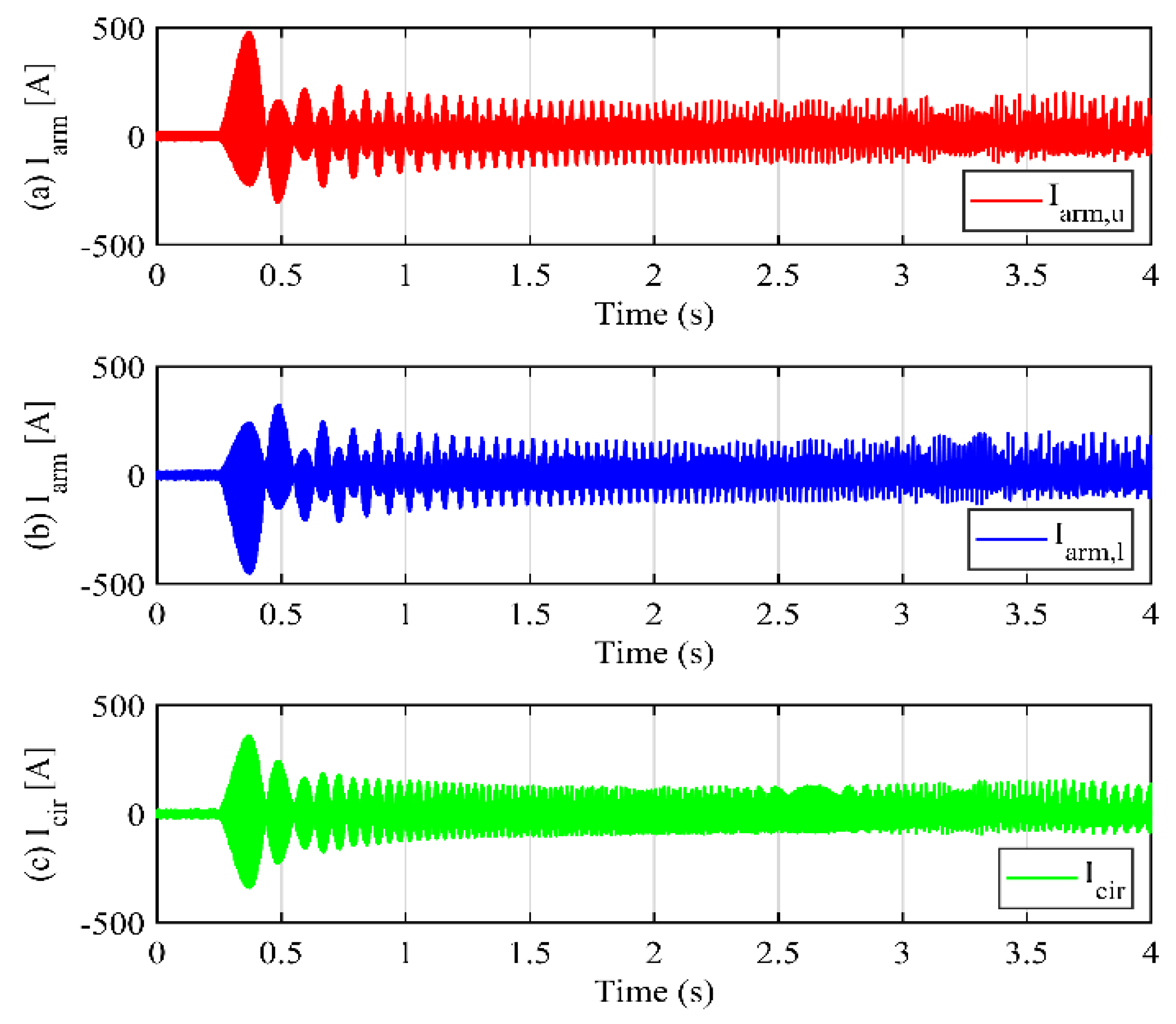
During motor acceleration, the increase in high-frequency circulating currents leads to distortion in the three-phase output current when the motor attains higher speeds (Figure 7b); potentially resulting in unstable operation of the motor converter system. Moreover, as shown in Figure 8, the arm current stress on the power semiconductor devices and the circulating current escalates due to the augmented high-frequency circulating currents. These factors necessitate the careful mitigation of high-frequency components on the AC side to preserve the high performance and reliability of the motor converter system.
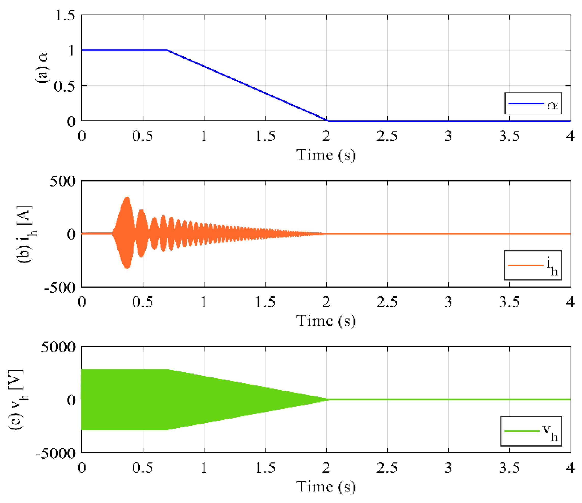
In this study, the fluctuation coefficient (α) is used to determine the amount of the high-frequency components injected into each arm, as shown in Figure 9. As discussed earlier, coefficient α is determined based on the change in the motor speed. During the acceleration of the motor (ωωL), coefficient α is controlled (α = 1) to fully inject the high-frequency components (vh and ih). At the time instant t = 0.7 s (ωLω < ωH), the coefficient α is determined as expressed in Equation (19) to decrease gradually, leading to a decrease in the injected high-frequency current and CMV (ih and vh). When ωωH, the injected high-frequency components are eliminated by controlling the fluctuation coefficient to zero; therefore, no high-frequency components are imposed on the motor side, which improves the motor system performance.
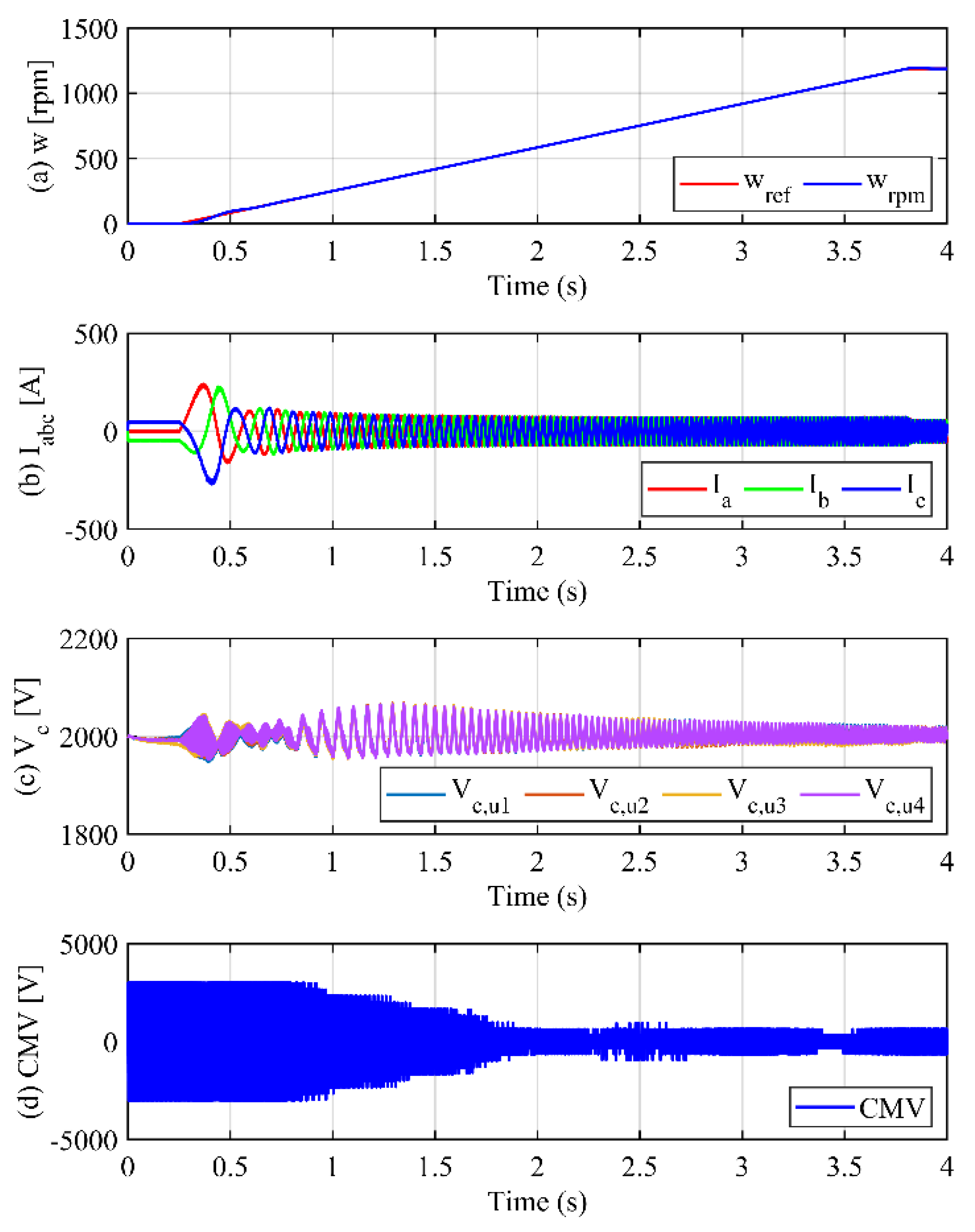
The performance of the proposed high-frequency injection method in driving an IM over the entire speed range under no-load conditions is shown in Figure 10. Similar to the conventional injection method [19], the high-frequency components are fully injected into each arm to address the SM voltage fluctuation during the motor’s low-speed operation (ωωL). As a result, the SM voltages are kept balanced at the reference value of 2000 V with a voltage fluctuation of 55 V, as shown in Figure 10b. When the motor speed is sufficiently high, the amplitudes of the injected high-frequency components decrease owing to a decrease in the fluctuation coefficient, as shown in Figure 9. Although the SM voltage fluctuation is larger than that shown in Figure 7c, the SM voltages are well balanced with Δvp-p ≈ 90 V which is less than 10% of the SM voltage. When ωωH, the injected high-frequency components are eliminated (α = 0) and the MMC operates in the normal operation mode. As a result, the CMV decreases gradually and fluctuates in the range of ±500 V which is much smaller than that of the conventional method. Additionally, the amplitudes of the arm current stress and circulating current are reduced significantly, as shown in Figure 11, and there is no distortion on the AC side, which proves that the proposed method does not inject high-frequency components.
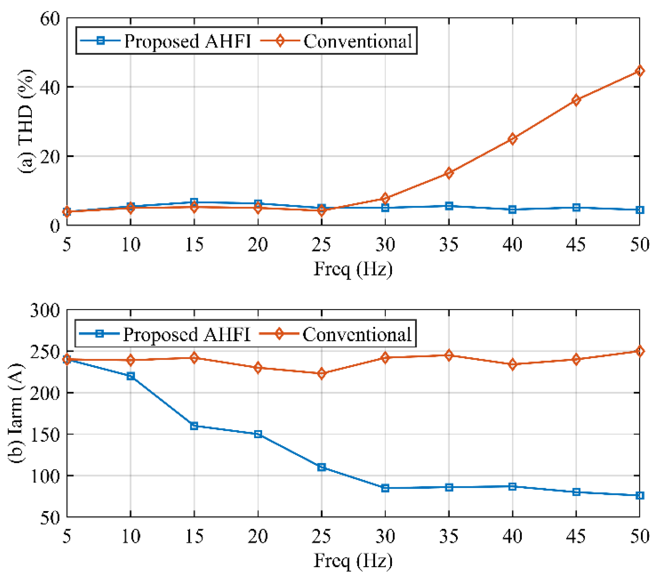
Figure 12 presents a performance comparison between the conventional harmonic injection method [19] and our proposed Adaptive High-Frequency Injection (AHFI) method, focusing on the Total Harmonic Distortion (THD) of the three-phase output current and the amplitude of arm current stress. This figure illustrates the significant advancements made by the AHFI method in improving the quality of the three-phase output current as motor speed increases, as depicted in Figure 12a. Unlike the conventional method, which may lead to increased THD at higher speeds, the AHFI method enhances the output current quality across the entire speed range, demonstrating its efficacy in maintaining lower THD levels even at higher operational speeds.
Furthermore, Figure 12b showcases the AHFI method’s ability to reduce current stress on the power semiconductors progressively. This reduction in current stress contributes to the longevity and reliability of the power electronic components within the MMC system, highlighting the AHFI method’s advantage in not only improving electrical performance but also in extending the operational life of critical system components.

5. Hardware-in-the-Loop Simulation

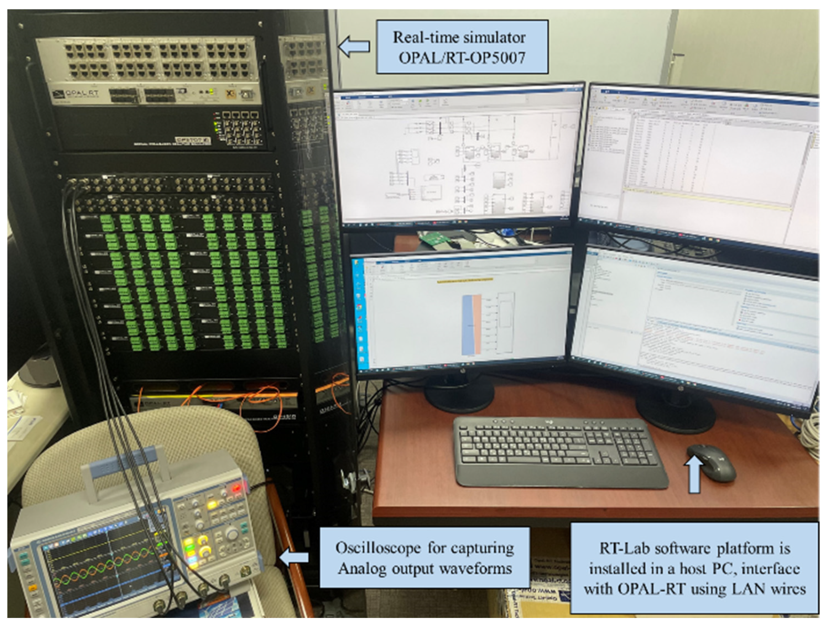
This section validates the effectiveness of the proposed AHFI method through hardware-in-the-loop (HIL) simulation, utilizing the OPAL-RT real-time digital simulator to generate computational waveforms that closely mimic those of an actual hardware setup. This approach ensures that the simulated waveforms can be reliably equated to those we would observe in a physical system.
The HIL simulation setup includes an OPAL-RT 5707 real-time simulator, oscilloscope, interface PC, and RT-Lab target PC, as depicted in Figure 13. We initially modeled the AHFI-enhanced MMC system using MATLAB/SIMULINK, which was then fully integrated with the RT-LAB platform for real-time interaction. The simulation operates synchronously at a time step of 10 µs, mirroring the functionality of actual hardware.
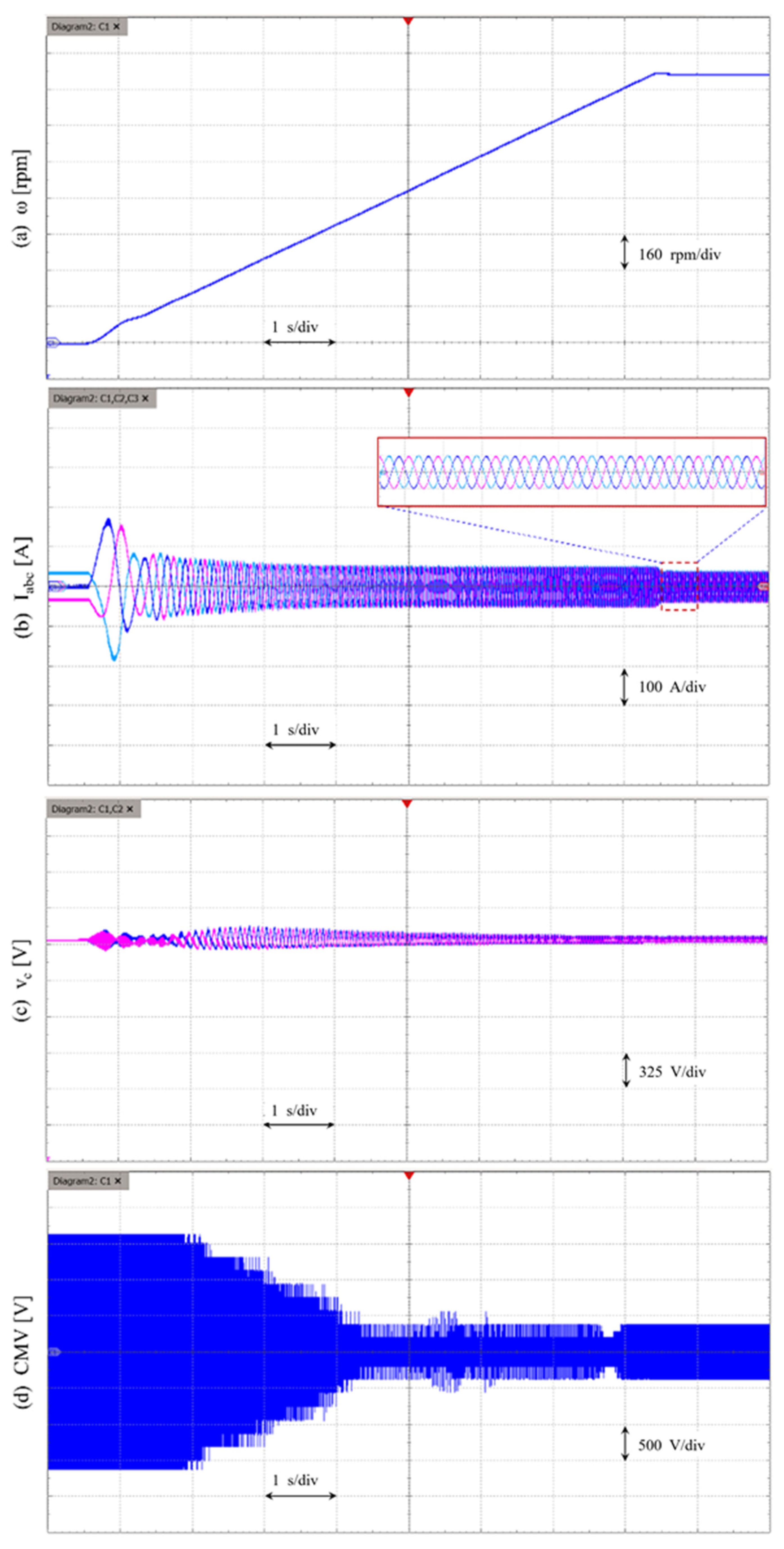
Figure 14 showcases the AHFI method’s performance across the entire motor speed range. It illustrates how the MMC system maintains a consistent three-phase current supply to the motor drives during acceleration, from standstill to the rated speed of 1189 rpm (Figure 14b), while keeping SM voltages at a 2000 V reference (Figure 14c). The injection of high-frequency components into each arm effectively reduces SM voltage fluctuation during acceleration, with a gradual reduction in injection as motor speed increases; facilitated by the adaptive adjustment of the fluctuation coefficient (α). Notably, even as the fluctuation coefficient decreases, leading to reduced SM voltage fluctuation, the peak-to-peak voltage fluctuation remains within 5% of the SM voltage reference (Figure 14c). Moreover, the CMV on the motor side is significantly reduced (Figure 14d), demonstrating the AHFI method’s capacity to enhance system stability and performance.
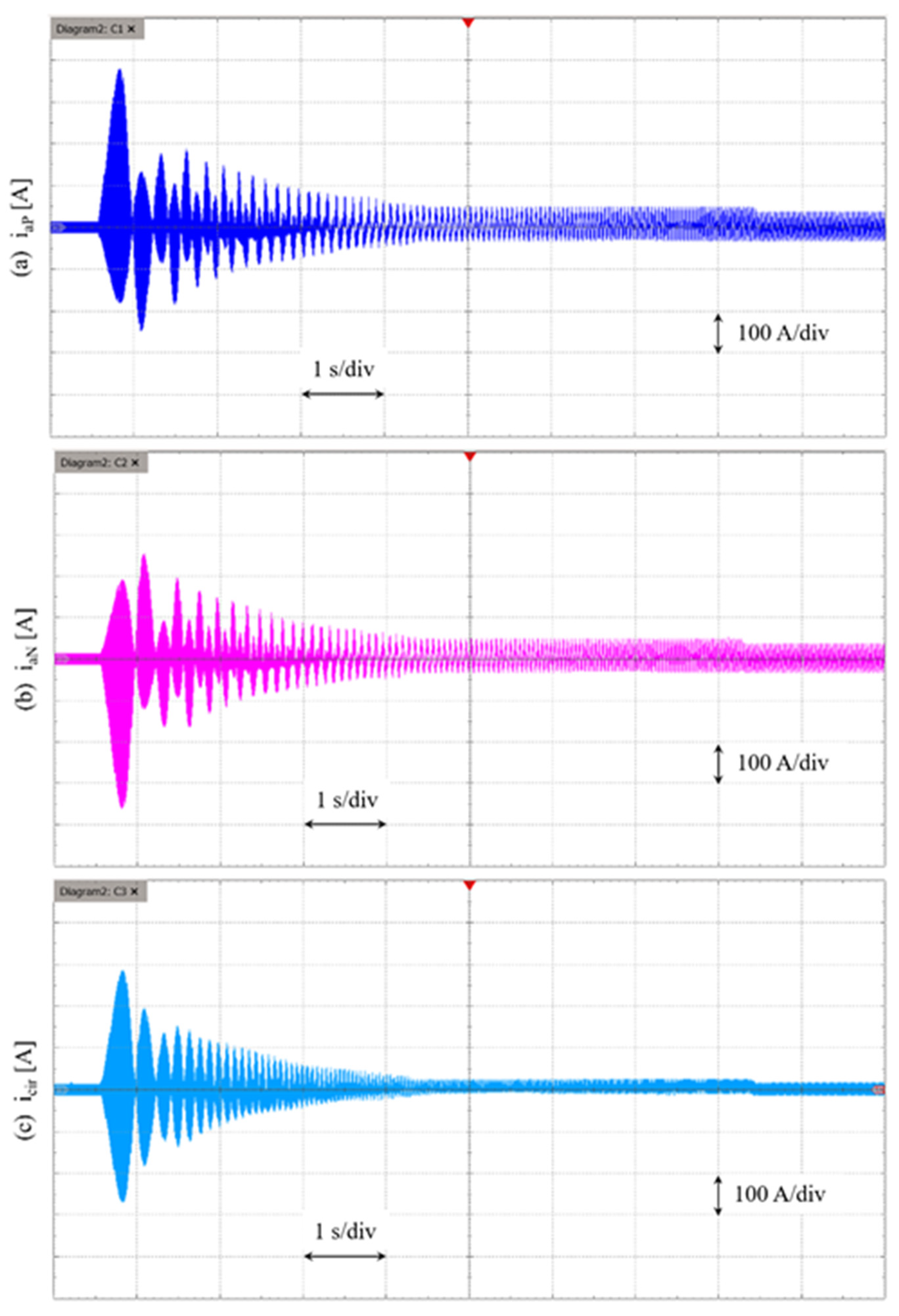
The arm currents and circulating current responses, obtained through the AHFI method, are presented in Figure 15. The figures illustrate a gradual reduction in current stress for both upper and lower arms as motor speed increases (Figure 15a,b), which concurrently leads to a decrease in circulating current (Figure 15c). This outcome further validates the AHFI method’s efficacy in optimizing the operational dynamics of MMC systems.

6. Conclusions

This study introduced the Adaptive High-Frequency Injection (AHFI) method; a novel approach for dynamically controlling high-frequency component injection in modular multilevel converters (MMCs), guided by the fluctuation coefficient. This method significantly enhances MMC system performance across the entire speed range of motor drives. By adaptively injecting high-frequency components, the AHFI method effectively mitigates submodule (SM) voltage fluctuations at low speeds and significantly reduces Common-Mode Voltage (CMV) at nominal speeds. This results in improved motor drive start-up performance and minimized CMV impact on motors. The practical effectiveness of the AHFI method has been validated through comprehensive simulation and real-time testing using MATLAB/SIMULINK and OPAL/RT simulator.
Quantitatively, our findings demonstrate a substantial reduction in Total Harmonic Distortion (THD), contributing to cleaner power quality and enhanced system efficiency. Specifically, the application of the AHFI method resulted in a THD reduction of up to 30% at critical operational speeds, marking a significant improvement over conventional method.
Our future research will focus on expanding the application scope of the AHFI method to a wider array of motor drive and power system configurations. Furthermore, a real Modular Multilevel Converter (MMC) system is currently being developed, within which we plan to integrate the AHFI method. This imminent practical application underscores our commitment to transitioning from theoretical research to tangible system enhancements.
We aim to explore the method’s adaptability and scalability for comprehensive system improvements. This includes the development of advanced control algorithms and the creation of robust hardware implementations for the AHFI method’s practical deployment. By pursuing these avenues, we anticipate making significant strides in improving the performance, efficiency, and reliability of motor drives and related power electronic systems, and meeting current challenges and anticipating future needs.
Author Contributions

Conceptualization, J.-W.L. and B.-G.P.; Formal analysis, J.-W.L.; Funding acquisition, J.-W.K.; Investigation, J.-W.L.; Methodology, J.-W.L.; Project administration, B.-G.P.; Resources, J.-W.L. and B.-G.P.; Software, J.-W.K. and J.-W.L.; Supervision, C.-W.L. and J.-W.K.; Validation, C.-W.L. and B.-G.P.; Visualization, J.-W.L.; Writing—original draft, J.-W.L.; Writing—review and editing, J.-W.L. All authors have read and agreed to the published version of the manuscript.

Funding

This research was supported by the Korea Electrotechnology Research Institute (KERI) primary research program through the National Research Council of Science & Technology (NST), funded by the Ministry of Science and ICT (MSIT) (No. 24A01057).

Data Availability Statement

The data presented in this study are available on request from the corresponding author. The data are not publicly available due to confidentiality reasons.

Conflicts of Interest

The authors declare no conflicts of interest.

References

  1. Debnath, S.; Qin, J.; Bahrani, B.; Saeedifard, M.; Barbosa, P. Operation, control, and applications of the modular multilevel converter. IEEE Trans. Power Electron. 2015, 30, 37–53. [Google Scholar] [CrossRef]
  2. Antonopoulos, A.; Angquist, L.; Nee, H.-P. On Dynamics and Voltage Control of the Modular Multilevel Converter. In Proceedings of the 2009 13th European Conference on Power Electronics and Applications, Barcelona, Spain, 8–10 September 2009; pp. 1–10. [Google Scholar]
  3. Saeedifard, M.; Iravani, R. Dynamic performance of a modular multilevel back-to-back HVDC system. IEEE Trans. Power Deliv. 2010, 25, 2903–2912. [Google Scholar] [CrossRef]
  4. Nami, A.; Liang, J.; Dijkhuizen, F.; Demetriades, G.D. Modular multilevel converters for HVDC applications: Review on converter cells and functionalities. IEEE Trans. Power Electron. 2015, 30, 18–36. [Google Scholar] [CrossRef]
  5. Tian, Y.; Wickramasinghe, H.R.; Li, Z.; Pou, J.; Konstantinou, G. Review, Classification and Loss Comparison of Modular Multilevel Converter Submodules for HVDC Applications. Energies 2022, 15, 1985. [Google Scholar] [CrossRef]
  6. Dong, P.; Lyu, J.; Cai, X. Modeling, analysis, and enhanced control of modular multilevel converters with asymmetric arm impedance for HVDC applications. J. Power Electron. 2018, 18, 1683–1696. [Google Scholar] [CrossRef]
  7. Diab, A.A.Z.; Ebraheem, T.; Aljendy, R.; Sultan, H.M.; Ali, Z.M. Optimal Design and Control of MMC STATCOM for Improving Power Quality Indicators. Appl. Sci. 2020, 10, 2490. [Google Scholar] [CrossRef]
  8. Mohammadi, H.P.; Bina, M.T. A transformerless medium-voltage STATCOM topology based on extended modular multilevel converters. IEEE Trans. Power Electron. 2011, 26, 1534–1545. [Google Scholar] [CrossRef]
  9. Pereira, M.; Retzmann, D.; Lottes, J.; Wiesinger, M.; Wong, G. SVC PLUS: An MMC STATCOM for network and grid access applications. In Proceedings of the IEEE Trondheim PowerTech Trondheim, Trondheim, Norway, 19–23 June 2011; pp. 1–5. [Google Scholar] [CrossRef]
  10. Le, D.D.; Hong, S.; Lee, D.C. Fault detection and tolerant control for flying-capacitor modular multilevel converters feeding induction motor drives. J. Power Electron. 2022, 22, 947–958. [Google Scholar] [CrossRef]
  11. Hagiwara, M.; Hasegawa, I.; Akagi, H. Start-up and low-speed operation of an electric motor driven by a modular multilevel cascade inverter. IEEE Trans. Ind. Appl. 2013, 49, 1556–1565. [Google Scholar] [CrossRef]
  12. Hagiwara, M.; Nishimura, K.; Akagi, H. A medium-voltage motor drive with a modular multilevel PWM inverter. IEEE Trans. Power Electron. 2010, 25, 1786–1799. [Google Scholar] [CrossRef]
  13. Li, B.; Zhou, S.; Xu, D.; Yang, R.; Xu, D.; Buccella, C.; Cecati, C. An Improved Circulating Current Injection Method for Modular Multilevel Converters in Variable-Speed Drives. IEEE Trans. Ind. Electron. 2016, 63, 7215–7225. [Google Scholar] [CrossRef]
  14. Zhao, F.; Xiao, G.; Zhu, T.; Zheng, X.; Wu, Z.; Zhao, T. A coordinated strategy of low-speed and start-up operation for medium-voltage variable-speed drives with a modular multilevel converter. IEEE Trans. Power Electron. 2020, 35, 709–724. [Google Scholar] [CrossRef]
  15. Antonopoulos, A.; Ängquist, L.; Norrga, S.; Ilves, K.; Harnefors, L.; Nee, H.-P. Modular Multilevel Converter AC Motor Drives with Constant Torque from Zero to Nominal Speed. IEEE Trans. Ind. Appl. 2014, 50, 1982–1993. [Google Scholar] [CrossRef]
  16. Kumar, Y.S.; Poddar, G. Control of Medium-Voltage AC Motor Drive for Wide Speed Range Using Modular Multilevel Converter. IEEE Trans. Ind. Electron. 2017, 64, 2742–2749. [Google Scholar] [CrossRef]
  17. Jung, J.J.; Lee, H.J.; Sul, S.K. Control strategy for improved dynamic performance of variable-speed drives with modular multilevel converter. IEEE J. Emerg. Sel. Top. Power Electron. 2015, 3, 371–380. [Google Scholar] [CrossRef]
  18. Marquardt, R. Modular Multilevel Converters: State of the Art and Future Progress. IEEE Power Electron. Mag. 2018, 5, 24–31. [Google Scholar] [CrossRef]
  19. Korn, A.J.; Winkelnkemper, M.; Steimer, P. Low output frequency operation of the Modular Multi-Level Converter. In Proceedings of the IEEE Energy Conversion Congress and Exposition, Atlanta, GA, USA, 12–16 September 2010; pp. 3993–3997. [Google Scholar] [CrossRef]
  20. Le, D.D.; Lee, D.C. Current Stress Reduction and Voltage Total Harmonic Distortion Improvement of Flying-Capacitor Modular Multilevel Converters for AC Machine Drive Applications. IEEE Trans. Ind. Electron. 2022, 69, 90–100. [Google Scholar] [CrossRef]
  21. Le, D.D.; Lee, D.C. Reduction of half-arm current stresses and flying-capacitor voltage ripples of flying-capacitor mmcs. IEEE Access 2020, 8, 180076–180086. [Google Scholar] [CrossRef]
  22. Nguyen, V.-T.; Kim, J.-W.; Lee, J.-W.; Park, B.-G. Optimal Design of a Submodule Capacitor in a Modular Multilevel Converter for Medium Voltage Motor Drives. Energies 2024, 17, 471. [Google Scholar] [CrossRef]
  23. Kong, Z.; Huang, X.; Wang, Z.; Xiong, J.; Zhang, K. Active Power Decoupling for Submodules of a Modular Multilevel Converter. IEEE Trans. Power Electron. 2018, 33, 125–136. [Google Scholar] [CrossRef]
  24. Wu, B.; Narimani, M. High-Power Converters and Ac Drives; John Wiley & Sons: Hoboken, NJ, USA, 2006. [Google Scholar]
  25. Hagiwara, M.; Akagi, H. Control and Experiment of Pulsewidth-Modulated Modular Multilevel Converters. IEEE Trans. Power Electron. 2009, 24, 1737–1746. [Google Scholar] [CrossRef]
Figure 1. Schematic representation of a three-phase MMC circuit configuration [22].
Energies 17 01367 g001
Figure 2. Peak-to-peak SM voltage fluctuation (Δvp-p) calculated from fluctuation coefficient (α) and operating frequency (fn).
Energies 17 01367 g002
Figure 3. Injected high-frequency components according to the variation of motor speed: (a) Fluctuation coefficient ( α ), (b) injected high-frequency current (Ih).
Energies 17 01367 g003
Figure 4. Block diagram illustrating the control of SM voltage balance: (a) balancing of phase voltages and regulation of circulating currents, (b) individual control for balancing SM voltages, (c) generation of SM voltage references.
Energies 17 01367 g004
Figure 5. Control block diagram of the MMC system based on the proposed AHFI.
Energies 17 01367 g005
Figure 6. Performance comparison between the conventional MMC method and the proposed AHFI: (a) conventional method without high-frequency injection, (b) proposed AHFI.
Energies 17 01367 g006aEnergies 17 01367 g006b
Figure 7. Performance of the conventional control method from zero to rated motor speed: (a) motor speed, (b) three-phase output current, (c) SM capacitor voltage, (d) CMV.
Energies 17 01367 g007
Figure 8. Response of arm currents and circulating current of the conventional control method: (a) upper arm current, (b) lower arm current, (c) circulating current.
Energies 17 01367 g008
Figure 9. The response of the proposed AHFI: (a) fluctuation coefficient (α), (b) injected high-frequency circulating current (ih), (c) injected high-frequency voltage (vh).
Energies 17 01367 g009
Figure 10. Performance of the proposed control method from zero to rated motor speed: (a) motor speed, (b) three-phase output current, (c) SM capacitor voltage, (d) CMV.
Energies 17 01367 g010
Figure 11. Response of arm currents and circulating current of the conventional control method: (a) upper arm current, (b) lower arm current, (c) circulating current.
Energies 17 01367 g011
Figure 12. Performance comparison between conventional method and proposed method: (a) THD of output current, (b) peak-to-peak arm current.
Energies 17 01367 g012
Figure 13. Laboratory setup of hardware-in-the-loop simulation platform using real-time simulator OPAL-RT.
Energies 17 01367 g013
Figure 14. Performance of the proposed control method from zero to rated motor speed: (a) motor speed, (b) three-phase output current, (c) SM capacitor voltage, (d) CMV.
Energies 17 01367 g014
Figure 15. Response of arm currents and circulating current of the conventional control method: (a) upper arm current, (b) lower arm current, (c) circulating current.
Energies 17 01367 g015
Table 1. System parameters.
ParametersSymbolsValues
DC-link voltageVDC8000 V
Number of SMs per armNSM4
Arm inductanceLarm1.5 mH
SM capacitanceCdc2700 uF
Switching frequencyfsw2000 Hz
Nominal frequencyfn50 Hz
Rated voltageVrated4160 V
Rated currentIrated200 A
Rated speedwrated1189 rpm
Rated torqueTrated7490 N·m
Disclaimer/Publisher’s Note: The statements, opinions and data contained in all publications are solely those of the individual author(s) and contributor(s) and not of MDPI and/or the editor(s). MDPI and/or the editor(s) disclaim responsibility for any injury to people or property resulting from any ideas, methods, instructions or products referred to in the content.