1. Introduction
In recent years, the adoption of medium-voltage DC (MVDC) distribution techniques has garnered significant interest as a burgeoning research area within the electric power industry [
1,
2,
3]. Compared to medium-voltage AC distribution systems, MVDC distribution networks offer several benefits, including higher control flexibility, lower line loss, and better compatibility with distributed renewable energy generations [
4,
5]. However, the conventional principle of AC electromagnetic induction is not directly transferable for the conversion of voltage and power in a DC context [
6]. Consequently, the DC transformer (DCT) based on power electronics technology becomes an indispensable key device in MVDC distribution networks [
7,
8].
From the perspective of achieving high-voltage and high-power applications, DCT topologies grounded in the Input-Series-Output-Parallel (ISOP) framework [
9,
10] and the modular multilevel architecture [
11,
12,
13] are both feasible schemes. Within the ISOP paradigm, the dual-active-bridge (DAB) converter [
14,
15,
16] is commonly used as a submodule (SM) to construct the DCT. The DAB proffers a simple structure, flexible control, and considerable power transmission capability. However, the DAB configuration is characterized by concentrated DC capacitors, which engender large DC fault currents, and it suffers from a deficiency of redundant SMs, thereby compromising DCT reliability [
17]. In light of these limitations, various improved DC/DC converters have been proposed in [
2,
7,
18,
19], with the intent to supplant the DAB in the ISOP-DCT construct and to rectify complications associated with DC fault clearing and the provision of redundant SM configurations. Nevertheless, these alternative DC/DC converters typically exacerbate power losses and increase the complexity of control methods. Furthermore, the issue of designing insulation for high-frequency transformers remains an unresolved challenge.
Conversely, the modular multilevel structure [
20,
21,
22] offers an alternative solution for the realization of DCTs within MVDC systems. The scalability of voltage and power levels in the MMC structure can be conveniently increased by stacking the required number of SMs. Meanwhile, redundant design can be achieved by adding additional SMs. Moreover, a DCT configured with the MMC topology exhibits inherent capabilities for DC fault clearance, thus positioning it as a secure and advantageous solution by obviating the necessity for dedicated DC circuit breakers within MVDC grids. In [
23,
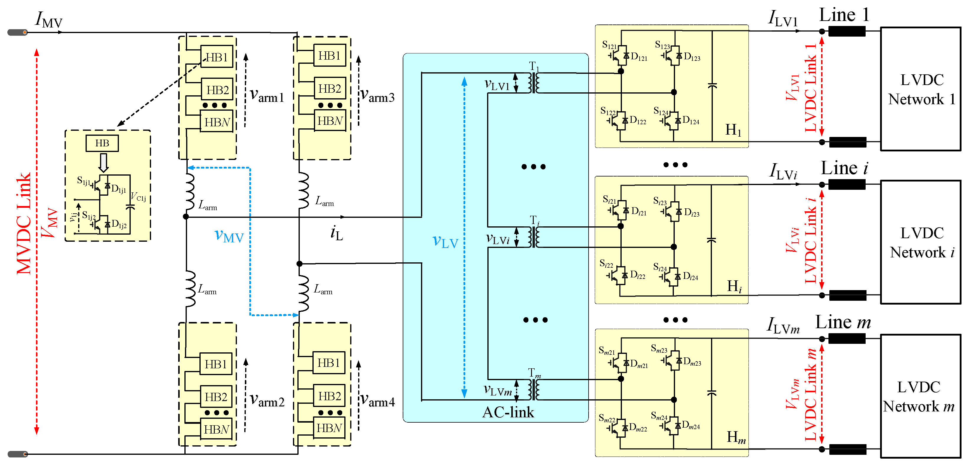
24], DCTs employing a face-to-face (F2F) modular multilevel structure are discussed; however, the modular multilevel configuration is not suitable for connecting low-voltage DC (LVDC). The rationale for this limitation is attributed to the high costs and low voltage utilization associated with the MMC in LVDC applications. Additionally, the F2F MMC-based DCT is not amenable to the construction of multiport DCTs due to its configuration constraints. An effective multiport modular multilevel DCT (M3DCT) based on a single-phase modular multilevel converter (MMC) and a series of cascaded H-bridge units is proposed in [
25], as shown in
Figure 1. The M3DCT’s MVDC interface employs a single-phase MMC configuration, facilitating connectivity with MVDC networks. In parallel, the LVDC interface of the proposed M3DCT comprises cascaded H-bridge units, which not only simplify the fabrication of AC-link transformers but also cater to the integration with multiport LVDC systems. As a result, the M3DCT configuration illustrated in
Figure 1 is posited as a robust and effective solution for bridging MVDC with multiport LVDC systems.
However, in a MVDC distribution network, the connection between the M3DCT and multiport LVDC systems typically involves DC lines, as shown in
Figure 1. Consequently, the LVDC-link voltages of the M3DCT exhibit fluctuations that are contingent upon the variability in power flow dynamics within the MVDC network. Such voltage fluctuations will cause mismatches between the AC-link voltage ratio of the M3DCT and the AC transformer voltage ratio, leading to degraded operational performance under conventional control [
26,
27,
28]. Some enhanced phase-shift control methods, namely extended-phase-shift (EPS) [
29], dual-phase-shift (DPS) [
30], and triple-phase-shift (TPS) [
31,
32,
33], have been developed to ameliorate AC-link circulating currents. Nonetheless, their effectiveness is compromised when the M3DCT operates at low power levels and experiences severe AC-link voltage mismatch ratios. The rationale is that EPS, DPS, and TPS control methods introduce supplementary degrees of freedom to the control system of DC/DC converters, with the primary objective of decreasing the reverse power flow in the AC-link. However, they do not explicitly target AC-link voltage matching as the actual optimization criterion. Moreover, the incorporation of EPS, DPS, or TPS into M3DCT presents challenges due to the requisite implementation of quasi-square-wave control [
26,
34] to mitigate the
dv/
dt on the AC-link and maintain a high dc voltage utilization. Despite the assertion in [
26] stating that the analyses of EPS, DPS, and TPS under a quasi-square-wave principle are similar to that of single-phase-shift (SPS) control within the same framework, the practical execution is considerably more intricate. This complexity arises from the fact that the incorporation of an additional internal phase-shift angle can potentially diminish the soft-switching performance of the switches and adversely affect the transmission capability of the DC/DC converter. The literature [
35] discusses a specialized AC-link voltage matching control, intending to solve the voltage mismatch issue. Albeit effective, this strategy is principally geared towards high-voltage DC (HVDC) applications, characterized by the presence of a multitude of SMs within each converter arm. In contrast, MVDC applications typically feature a considerably smaller number of SMs per arm, with counts ranging from several to a few dozen [
36,
37]. Therefore, the conventional AC-link voltage matching control (CVM) discussed in [
35] lacks the granularity necessary for effective voltage regulation within MVDC applications. To address this issue, this paper introduces an improved AC-link voltage matching control (IVM) specifically conceived for the M3DCT within MVDCs, aiming to effectively solve the issue of AC-link voltage mismatches.
The rest of this article is organized as follows. In
Section 2, the AC-link voltage mismatching phenomenon of the M3DCT is analyzed.
Section 3 discusses the proposed IVM. Simulation results are presented in
Section 4. Finally,
Section 5 concludes this article.
2. Analysis of AC-Link Voltage Mismatching Phenomenon in M3DCT
In the M3DCT, the DC-link and AC-link voltage mismatch ratios are defined as:
where A(x) is the amplitude function of x;
VMV represents the MVDC-link voltage of the M3DCT;
VLV1 to
VLVm represent the LVDC-link voltages of H
1 to H
m, respectively;
kT1 to
kTm represent the voltage ratio of the AC transformers connected to H
1 to H
m, respectively;
vMV is the MVAC-link voltage;
vLV represents the equivalent voltage of the sum of LVAC-link voltages (
vLV1 + … +
vLVm) on the MVAC side;
vLV1 to
vLVm represent the equivalent voltages of LVAC-link voltages in H
1 to H
m, respectively, on the MVAC side;
ξDC and
ξAC are the DC-link and AC-link voltage mismatch ratios of the M3DCT, respectively.
According to (1), the operational condition of the M3DCT is characterized as the DC-link voltage matching state when ξDC = 0. Conversely, when ξDC ≠ 0, the state is defined as the DC-link voltage mismatching state. Furthermore, an increment in the magnitude of ξDC is indicative of an escalating disparity between the DC voltage and the AC transformer turns ratio. The rationale for the interpretation of ξAC is congruent with this line of reasoning. It is important to note that the key distinction between ξDC and ξAC, as outlined in (1), is due to the variables VMV and A(vMV). By actively controlling A(vMV) within the M3DCT, it is possible to maintain the AC-link voltage in a matching state, regardless of any fluctuations in the DC-link voltage. Conversely, if there is no decoupling between A(vMV) and VMV in the M3DCT system, the operational state of the AC-link voltage will be directly linked to the operational state of the DC-link voltage. In other words, ξAC = ξDC.
In the configuration of an MVDC distribution network, the MVDC-link voltage (
VMV) of the M3DCT is typically regulated by the upstream power electronic converter connected to the MVDC bus. Thus, even when the transmission power changes,
VMV always remains constant at its rated value (
VMVra). In contrast, the LVDC-link voltages (
VLV1 to
VLVm) are subject to change with the power flow because they are usually connected to LVDC systems through DC distribution lines, as illustrated in
Figure 1. Since the voltage at LVDC buses in LVDC systems is managed by those systems, the LVDC-link voltages of the M3DCT can be derived as follows:
where
VLVnet1 to
VLVnetm represent the LVDC bus voltages of LVDC system1 to LVDC system
m, respectively;
ILV1 to
ILVm represent the LVDC-link currents of H
1 to H
m, respectively; and
Rlinej(j=1…m) is the equivalent resistance of the DC distribution lines.
In (2), only the voltage variation induced by the resistance in the DC distribution line is included. The rationale behind this is that even though the DC distribution line possesses reactance, the resultant voltage change in steady-state conditions can be neglected relative to the change brought about by resistance, given the tiny fluctuation of the DC current. Conversely, the reactance of the DC distribution line exerts a greater impact on the dynamic behavior during power changes; however, it has negligible effect on the steady-state DC voltage.
In practical applications, for ensuring optimal performance of the M3DCT during rated power operation, the required voltage of the LVDC bus connected to M3DCT in each LVDC system should be regulated as:
where
VLV1ra to
VLVmra are the rated LVDC-link voltages of H
1 to H
m, respectively;
VLVnetD1 to
VLVnetDm represent the desired LVDC bus voltages of LVDC system1 to LVDC system
m, respectively;
ILV1ra to
ILVmra represent the rated LVDC-link currents of H
1 to H
m, respectively.
That is, at rated power, the LVDC bus voltage within each LVDC system should be regulated to ensure that the M3DCT’s individual LVDC-link voltages operate at their rated values. This regulation is crucial for enhancing the performance of the M3DCT during rated power operations. However, as the power level varies, the actual LVDC-link voltage values, VLV1 to VLVm, will experience fluctuations, which can impact the performance of the M3DCT. These fluctuations are particularly pronounced at extremely low power levels, where VLV1 to VLVm can significantly deviate from their rated voltages. As a result, vLV, which represents the composite voltage of the sum of LVDC-link voltages (vLV1 + … + vLVm) on the MVAC side, will also exhibit significant deviation from its rated value, vLVra.
Due to the AC transformer ratios,
kT1 to
kTm, within the M3DCT, are typically designed to align with rated conditions:
The deviation of VLVj from VLVjra indicates that the DC-link voltage of the M3DCT is no longer in the matching state. Since A(vMV) and VMV are not decoupled in the conventional control of M3DCT, the mismatch in the DC-link voltage mentioned above will result in a corresponding mismatch in the M3DCT’s AC-link voltage. Consequently, both the AC-link voltage mismatch and the low operating power will decrease the performance of the M3DCT.
Figure 2 illustrates the abovementioned phenomenon of AC-link voltage mismatch in the M3DCT. Obviously, even though the M3DCT operates at a low transmission power of 0.1 p.u., the AC-link current is only about 0.08 p.u. of the rated current, and the arm current is merely around 0.06 p.u. of the rated value when the AC-link voltage is matched. However, if the AC-link voltage is mismatched (with
ξAC = 14%), the AC-link current for the M3DCT increases to approximately 0.25 p.u. of the rated current, and the arm current escalates to about 0.16 p.u. of the rated current. That is, the AC-link current stress and the circulating power become exceedingly high when there is a mismatch in the AC-link voltage, which substantially diminishes the performance of the M3DCT. Meanwhile, addressing this issue effectively requires achieving AC-link voltage matching.
3. Implementation Scheme for the Proposed Improved AC-Link Voltage Matching Control (IVM)
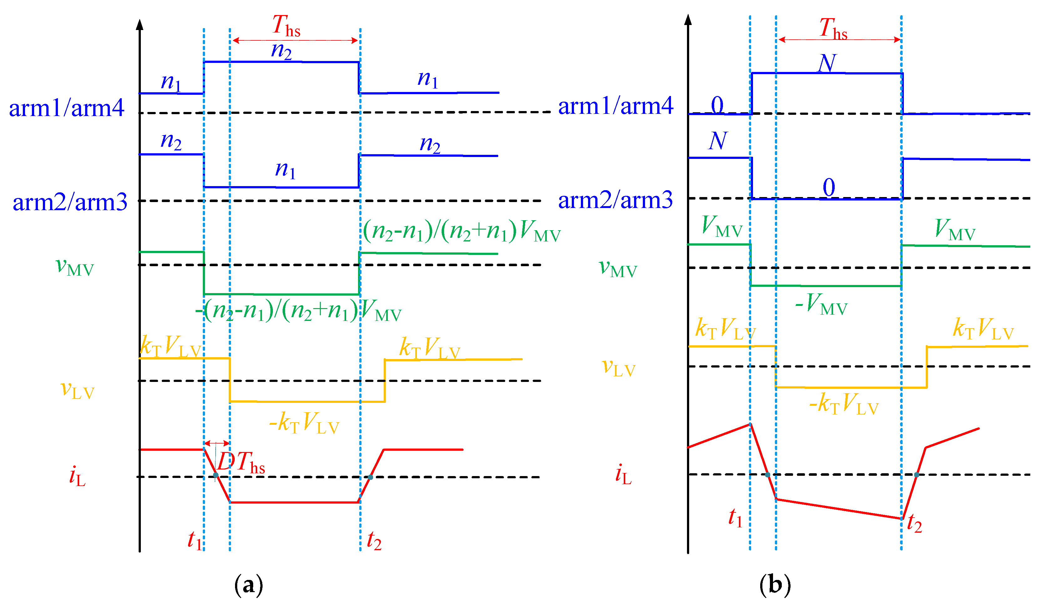
In the M3DCT, the matching state of the DC-link voltage can be decoupled from that of the AC-link voltage due to the modular multilevel structure on the MVDC side. Essentially, by refining the control strategy, it is feasible to attain a matched state for the AC-link voltage in the M3DCT, irrespective of any mismatch in the DC-link voltage. The implementation principles of the proposed IVM are presented in
Figure 3a. When contrasted with the conventional control of the M3DCT depicted in
Figure 3b, the proposed IVM exhibits two key advantages. First, there is no longer a limitation on the total number of SMs inserted in the upper and lower arms of the M3DCT. The number of SMs per arm, denoted as
N, can be exceeded, providing increased flexibility in control. Second, the number of SMs inserted per moment in each arm is no longer limited to
N. This means that the number of SMs can be dynamically adjusted according to the control requirements. Leveraging these two features, the proposed IVM is capable of effectively achieving AC-link voltage matching control in M3DCT systems.
According to
Figure 3a, at any given moment, the total number of SMs inserted in both the upper and lower arms of the MMC structure on the medium-voltage side of the M3DCT is always equal to (
n1 +
n2). Taking arm1 and arm2 as examples, when arm1 has
n1 SMs inserted, arm2 has
n2 SMs inserted. Conversely, when arm1 has
n2 SMs inserted, arm2 has
n1 SMs inserted. Meanwhile, both arm1 and arm2 maintain a duty ratio of 50%. This implies that for any arm, if
n1 SMs are inserted during the first half of the switching cycle, then
n2 SMs will be inserted during the second half of the switching cycle.
As shown in
Figure 4, the output voltage of SM is dependent on its operational state, irrespective of the current direction in the arm. Specifically, when the SM is in the inserted state, its output voltage is equal to the capacitor voltage. Conversely, when the SM is in the bypass state, its output voltage is zero. Owing to the modulation algorithm [
38,
39] and the strategy for capacitor voltage equalization, the voltage across the capacitors of all SMs in each arm of the M3DCT is made uniform. Consequently, for an arm with
N SMs, as depicted in
Figure 1, if
n1 SMs are in the inserted state, the voltage of the arm can be expressed as follows:
where
varm represents the arm voltage of the discussed arm;
VC represents the capacitor voltage per SM of the discussed arm.
Similarly, for an arm with
N SMs, if
n2 SMs are in the inserted state, the arm voltage can be expressed as:
According to (5), (6), and
Figure 3a, in M3DCT, the capacitor voltage per SM in the proposed IVM can be derived as:
Then, the arm voltages in the proposed IVM can be derived as:
where
Ths represents the half-switching period of the M3DCT.
Meanwhile, the MVAC-link voltage
vMV in the M3DCT can be obtained based on the arm voltages:
Assuming the phase-shift angle between
vMV and
vLV is
DThs, the voltage
vLV is:
Based on (9) and (10), to achieve the AC-link voltage matching control for the M3DCT,
n1 and
n2 should satisfy the following requirement:
In addition,
n1 and
n2 should ensure that the capacitor voltage of the MVDC-link SM remains within the required maximum and minimum values. That is:
where
VCmin and
VCmax represent the required maximum and minimum values of the capacitor voltage in the M3DCT.
Equations (7), (11) and (12) offer a detailed explanation of the fundamental control principle behind the proposed IVM. As discussed in
Section 2, the equivalent sum of the LVAC link voltages on the MVAC side (
vLV) of the M3DCT will decrease as the transmission power decreases. Meanwhile, the MVAC-link voltage (
vMV) and the MVDC-link voltage (
VMV) of the M3DCT remain constant at their rated values. Consequently, Equations (11) and (12) can be reformulated as follows:
According to (13), similar to the CVM described in [
35], the M3DCT in the proposed IVM primarily controls
n1 and
n2 to achieve
ξAC = 0 when
ξDC ≠ 0. As a result, the interval during which the voltage is regulated, known as the unit regulated interval, is also a critical factor influencing the efficacy of the control method. The unit voltage-regulated interval for the proposed IVM is analyzed in detail as follows.
In fact, both the conventional control of M3DCT and the CVM as presented in [
35] can be considered special operating conditions of the proposed IVM. The detailed conversion relationships are as follows: when
n1 = 0 and
n2 =
N, the proposed IVM is equivalent to the conventional control; when
n1 +
n2 =
N, the proposed IVM is equivalent to the CVM. Therefore, the proposed IVM offers more flexible control than both the conventional control and the CVM. In particular, compared to the CVM, the proposed IVM allows for a more flexible adjustment of the unit-regulated interval. As a result, the proposed IVM can overcome the limitations of the CVM.
Taking the M3DCT with parameters listed in
Table 1 as a case, assume that the deviation of the sum of the LVDC-link voltages for the M3DCT is ±10%, which implies that the minimum amplitude for the combined voltage (
vLV1 + … +
vLVm) is 16 kV. According to the parameters in
Table 1, if the CVM is employed in the M3DCT, the unit voltage regulated interval of the MVAC-link voltage would be the twice that of the capacitor voltage (0.5 kV). As a result, the matching control of the M3DCT may not be achievable in certain conditions. Conversely, by applying the proposed IVM method to the M3DCT, these constraints can be circumvented. For example, when (
kT1VLV1 + …+
kTmVLVm) = 17.5 kV (
ξDC = 14%), the CVM method would fail to regulate the amplitude of the MVAC-link voltage (
vMV) to match 17.5 kV. With
n1 = 2 and
n2 = 38, the amplitude of
vMV would be 18 kV, and with
n1 = 3 and
n2 = 37, it would be 17 kV. However, the proposed IVM method can achieve the desired match with
n1 = 2 and
n2 = 30. As a result, the voltage per SM capacitor is 0.625 kV, which exceeds the rated value but is still below the maximum allowable capacitor voltage.
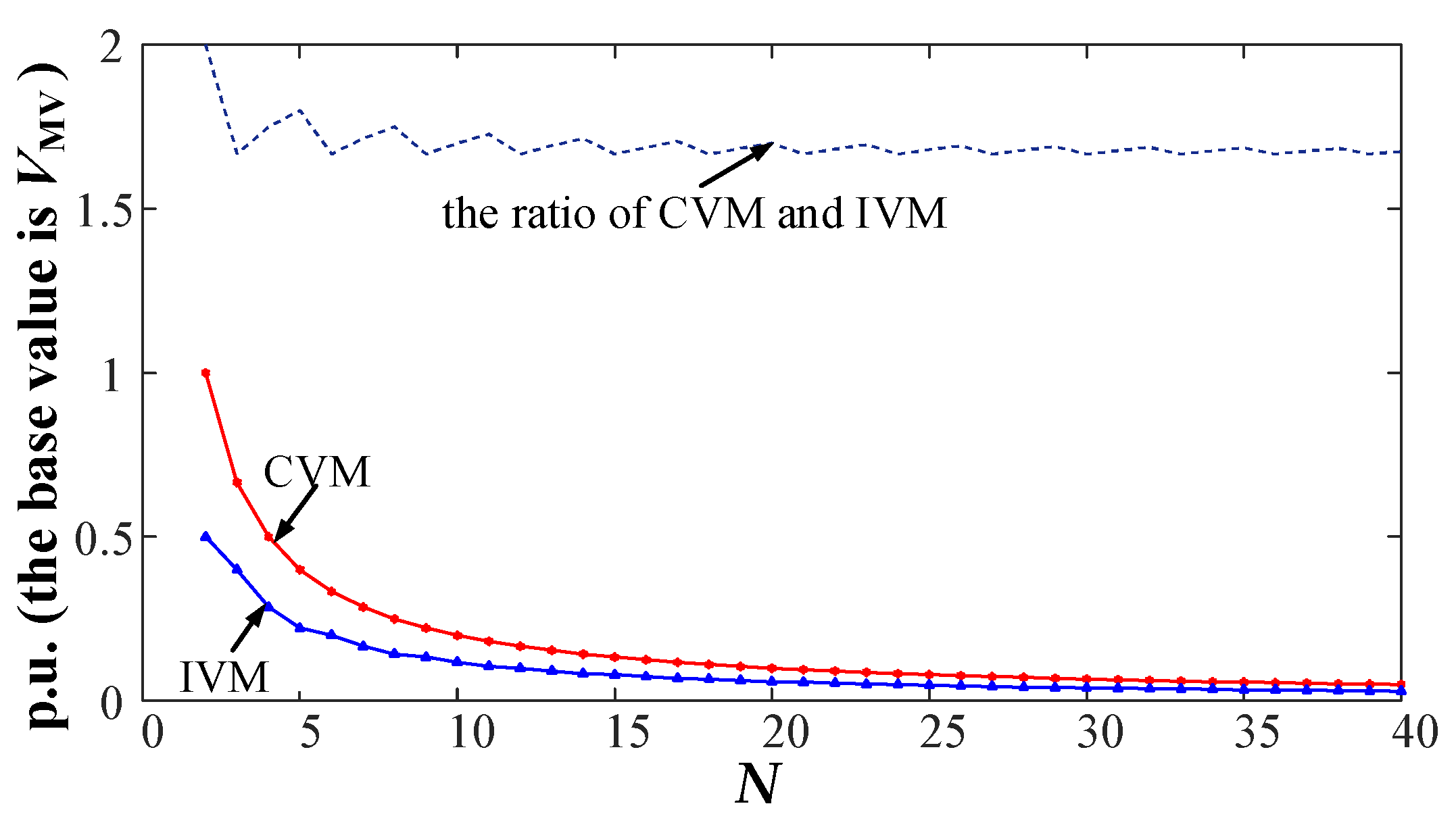
Furthermore, based on the parameters listed in
Table 1, the minimum and maximum voltages permitted for the SM capacitors in the M3DCT are 0.6 and 1.4 times the rated value, respectively. Given these constraints,
Figure 5 illustrates the relationship between the number of SMs per arm and the interval of unit voltage regulation. As shown in
Figure 5, the interval of unit voltage regulation decreases with an increasing number of SMs per arm for both the proposed IVM and the CVM. Meanwhile, the proposed IVM consistently exhibits a smaller voltage regulation interval compared to the CVM. The ratio between the proposed IVM and the CVM approaches a fixed value as the number of SMs per arm increases. Theoretically, if the number of SMs per arm were infinite, this ratio would approach
VCrate/
VCmin.
According to the analysis above, the minimum allowable capacitor voltage in the proposed IVM determines the interval of unit voltage regulation within the IVM. The maximum allowable capacitor voltage in the proposed IVM extends the control flexibility of the IVM. In other words, by designing the operating range of the SM capacitor voltage of the M3DCT, the proposed IVM achieves a more flexible and effective AC-link voltage control capability.
4. Verification
To validate the correctness of the theory, models were constructed based on the parameters provided in
Table 1 using MATLAB/Simulink, and the detailed results are presented in
Figure 6,
Figure 7 and
Figure 8.
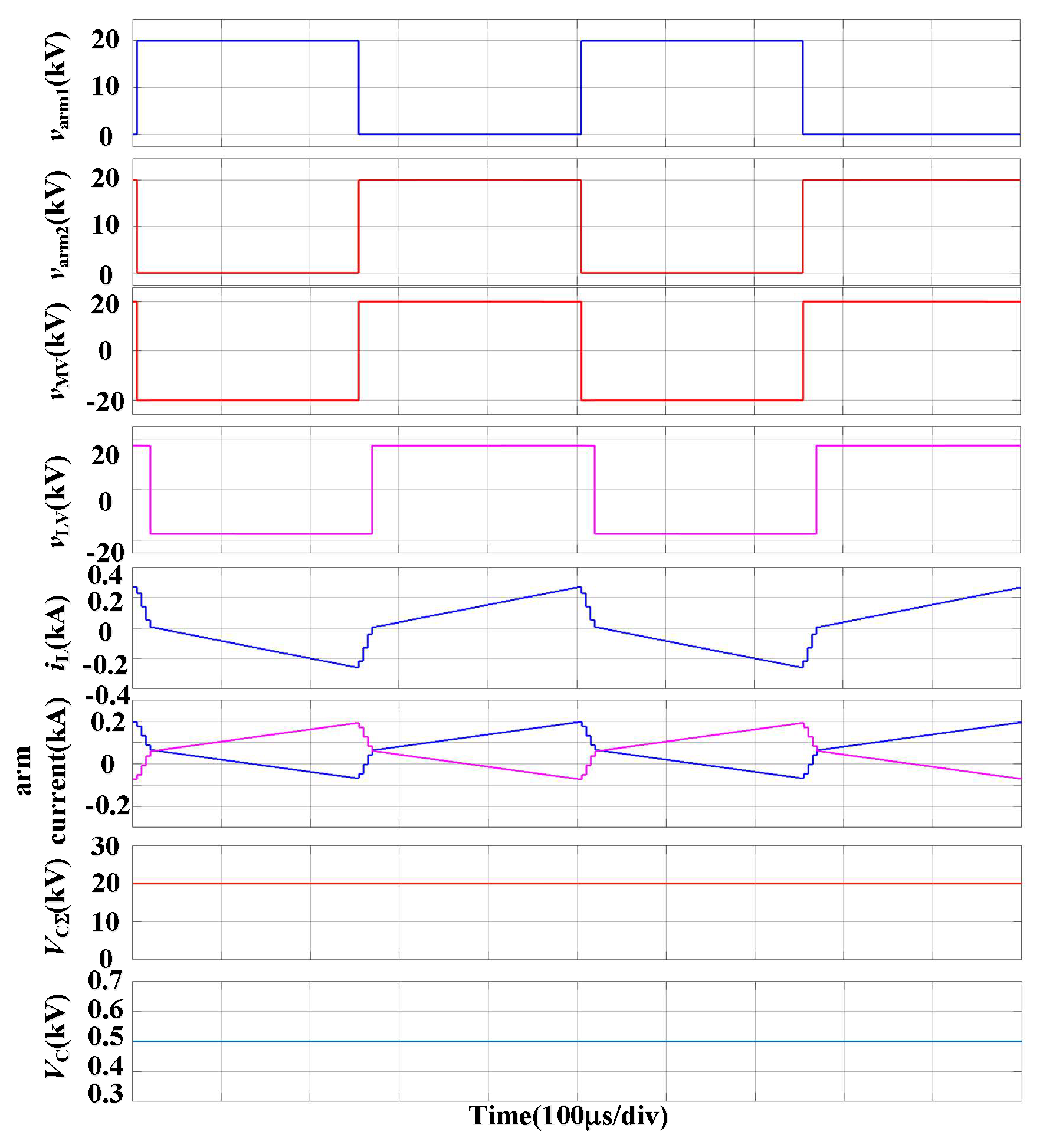
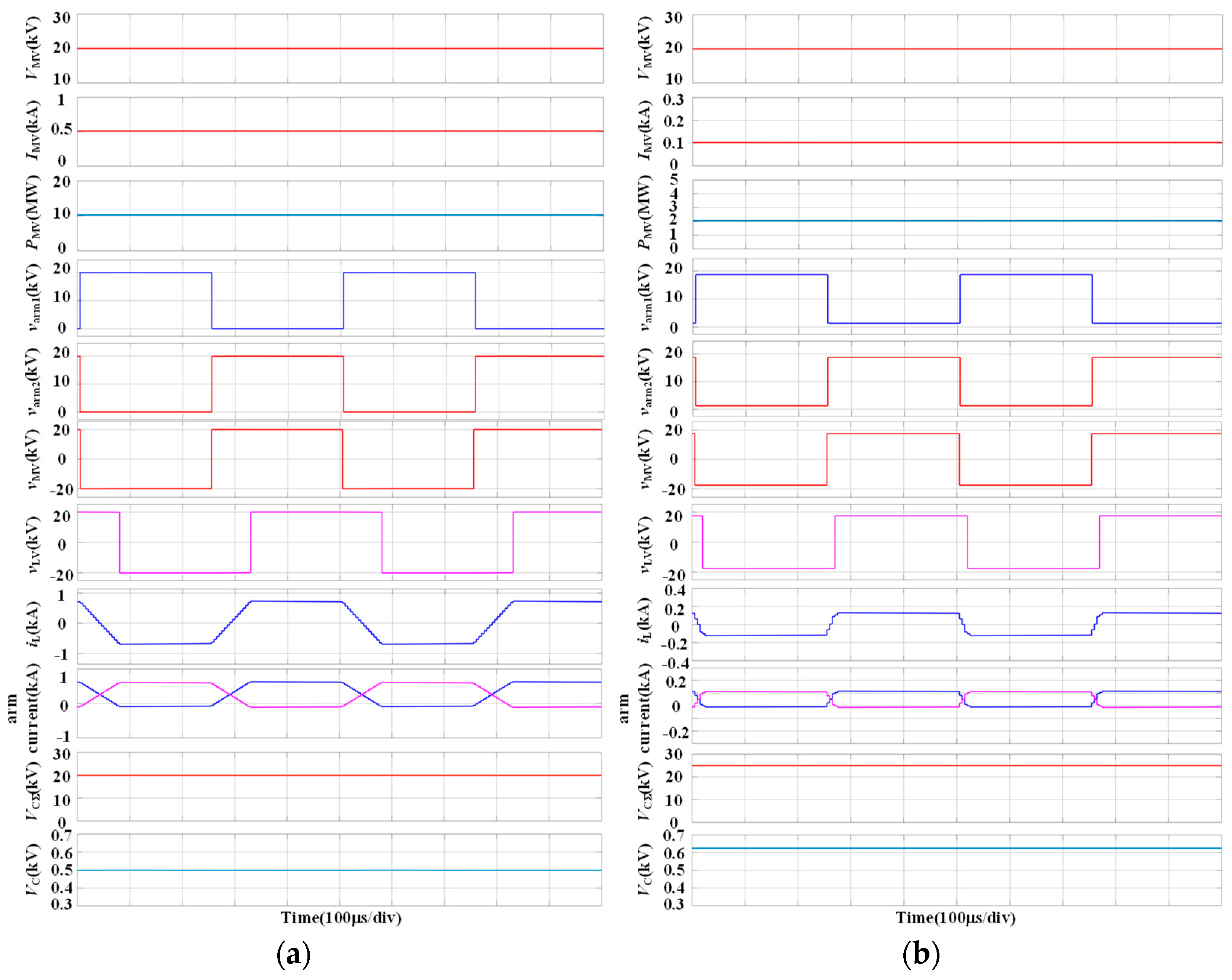
In
Figure 6a, the M3DCT is operating at its rated power while utilizing the proposed IVM. Both the MVDC-link voltage and each LVDC-link voltage are maintained at their rated levels, ensuring that the AC-link voltage of the M3DCT is in a matching state. During this period, the maximum and minimum values of the arm output voltage (
varm1 and
varm2) are 20 kV and 0 kV, respectively. Consequently, the amplitude of the MVAC voltage (
vMV) of the M3DCT is 20 kV, and the sum of the capacitor voltages per arm is also 20 kV. Meanwhile, the SM capacitor voltage VC is regulated at 0.5 kV, which corresponds to its rated value. Additionally, the maximum values of the arm currents and the AC-link current in this scenario are 0.6 kA and 0.74 kA, respectively. These results demonstrate the effectiveness of the proposed IVM in maintaining system performance at the rated transmission power.
In
Figure 6b, the M3DCT operates at a low power level of 20% using the proposed IVM. In this scenario, the MVDC-link voltage of the M3DCT is 20 kV, while the total LVDC-link voltages sum up to 17.5 kV. This indicates that the MVDC-link voltage and (
kT1VLV1 + …+
kTmVLVm) are not in a matched state, with a mismatch of 14% (
ξDC = 14%). During this period, the maximum and minimum values of the arm output voltage (
varm1 and
varm2) are 18.75 kV and 1.25 kV, respectively. Consequently, the amplitude of the MVAC voltage (
vMV) of the M3DCT is 17.5 kV, and the total capacitor voltages per arm amount to 25 kV. The capacitor voltage in this situation is 0.625 kV, and the maximum values of the arm currents and the AC-link current in this case are 0.11 kA and 0.13 kA, respectively. These results demonstrate the effectiveness of the proposed IVM in low power transmission.
The simulation results in
Figure 6a,b demonstrate that in the analyzed scenario, the capacitor voltage of the SM in the proposed IVM needs to exceed its rated value in order to match the MVAC-link voltage (while still staying within the maximum allowable value). In other words, the maximum allowable capacitor voltage in the proposed IVM extends the control flexibility of the IVM. This finding is consistent with the theoretical analysis presented in
Figure 5.
Furthermore,
Figure 7 illustrates the simulation results of the conventional control approach when the M3DCT operates at a light load of 20% and a mismatch ratio (
ξDC) of 14%. As depicted in
Figure 7, the maximum and minimum values of the arm output voltage (
varm1 and
varm2) are 20 kV and 0 kV, respectively. Consequently, the amplitude of the MVAC voltage (
vMV) in the M3DCT is 20 kV, and the sum of the capacitor voltages per arm also amounts to 20 kV. However, the equivalent voltage of the sum of LVAC-link voltages on the MVAC side (
vLV) in the M3DCT is 17.5 kV, indicating that the M3DCT is operating with a mismatch in the AC-link voltage. As a result, the maximum values of the arm currents and the AC-link current in this case are 0.2 kA and 0.26 kA, respectively. Clearly, when compared to the operating results depicted in
Figure 6b, the increase in arm currents and the AC-link current has a negative impact on the performance of the M3DCT. These results confirm the correctness of the theoretical analysis.
Figure 8 shows the dynamic simulation results of the M3DCT, transitioning from a rated operating state to a light-load operating state (20% of the rated power and
ξDC = 14%). It can be observed that, as the sum of the LVC-Link voltage decreases from 20 kV to 17.5 kV, the LVAC-link equivalent voltage of the M3DCT swiftly decreases from 20 kV to 17.5 kV, while the MVAC-link voltage smoothly drops to 17.5 kV under the control of the proposed IVM. During this process, as the sum of the SMs inserted in the upper and lower arms on the MVDC side of the M3DCT simultaneously changes from 40 to 32 at each moment, the capacitor voltage of each SM increases, resulting in a rise in the total capacitor voltage sum of the SMs in each arm.
5. Conclusions
This paper proposes a novel control strategy called improved AC-link voltage matching control (IVM) for a multiport modular multilevel DC transformer (M3DCT), which is utilized to connect MVDC and multiport LVDC systems in distribution networks. The primary objective of the proposed IVM is to address the issue of AC-link voltage mismatch. Unlike conventional AC-link voltage matching control methods, the IVM not only regulates the AC-link voltages of the M3DCT by adjusting the number of inserted SMs per arm in real-time but also regulates the sum of the SMs inserted into the upper and lower arms. This additional control degree of freedom enables a more flexible adjustment of the unit regulated interval in the proposed IVM, facilitating effective matching of the AC-link voltages, especially in extreme conditions, with low transmission power and high AC-link voltage mismatch ratio. Based on the analysis of the results presented in this paper, it has been demonstrated that the maximum values of the arm currents and the AC-link current in the proposed IVM can be reduced by half in the AC-link voltage mismatch state, compared to the conventional control of the M3DCT. This improvement in current values will lead to increased transmission efficiency, enhancing the overall performance of the M3DCT. The findings of this paper will contribute to the implementation of M3DCT in MVDC distribution networks, further promoting their development.
Furthermore, according to the analysis presented in this paper, it is crucial to extend the operating range of the SM capacitor voltage. This extension is necessary to ensure that the IVM can accommodate the required minimum and maximum capacitor voltage values. The minimum allowable capacitor voltage in the proposed IVM determines the interval of unit voltage regulation, while the maximum allowable capacitor voltage enhances the control flexibility of the IVM. However, extending the operating range of the SM capacitor voltage requires changes in M3DCT’s protection technology and imposes higher demands on the capacitor voltage. Therefore, in practical applications, it is necessary to consider the benefits brought about by the proposed IVM, as well as the challenges posed by the capacitor voltage and protection design. This consideration will lead to a comprehensive optimization of the M3DCT.
To further investigate the feasibility of the proposed IVM in the M3DCT, a test prototype of the M3DCT will be constructed in the future. Additionally, based on this prototype, further discussions on the M3DCT, such as fault ride-through, redundant control, and various actual operating conditions, will be conducted.


