1. Introduction
The increasing rate of carbon emissions and its effects on climate worldwide has led to the study of different approaches for CO
2 sequestration, as this is considered critical for mitigating climate change and protecting the environment. Studies on CO
2 sequestration have been in place since the 20th century [
1] but have now received global attention from researchers, scientists, and engineers working towards a net zero carbon emissions goal. Several countries from around the world are recognizing the viable role of CO
2 sequestration in climate change mitigation, including but not limited to the US, UK, China, and Norway [
2].
The aim to achieve net zero emissions has gathered pace in the last decade, and the number of countries committed to it continue to grow. The goal of reducing net carbon emissions to zero by 2050 and limiting the rise in global temperatures to 1.5 °C was initiated during the 2015 Paris Climate Agreement [
3]. The 26th Conference of the Parties (COP26) of the United Nations Framework Convention on Climate Change in November 2021 strengthened this ambition.
Numerical reservoir modeling has been an efficient method to study and design geological carbon sequestration projects and evaluate the potential CO
2 migration within subsurface rock formations. Some case studies that have applied numerical reservoir models to CO
2 geological storage include projects located offshore of Norway [
4,
5]; the Cranfield pilot project [
6]; and the Frio pilot project [
7]. Sedimentary basins offshore of Norway consist of a number of saline aquifers that have large storage potentials for CO
2. The Sleipner project is one such example that presents a successful case study, injecting ∼13.5 Mt of CO
2 from 1994 to 2012 in the Utsira formation [
8]. In addition to sites that are regional hubs, there is a desire for local sites where CO
2 can be captured from emitters located above appropriate geology for CO
2 storage.
There are several opportunities to expand and further evaluate numerical simulations and reservoir models using the existing CO
2 storage projects worldwide. In this work, we present an example of upscaling the CO
2 storage in an onshore brine-filled reservoir (Mount Simon Sandstone) using the Illinois Basin–Decatur Project (IBDP) and the Illinois Industrial Carbon Capture and Storage (IL-ICCS) project as a reference. IBDP CO
2 storage was carried out by the Midwest Geological Sequestration Consortium (MGSC) and led by the Illinois State Geological Survey (ISGS) [
9]. The IBDP identified Archer Daniels Midland Company (ADM, Chicago, IL, USA), an ethanol plant, as the source of CO
2 and injected a total of 1 mega tonnes (Mt) of CO
2 from 2011 to 2014 [
9]. The IL-ICCS project was a further development to the IBDP to study the interaction of CO
2 plumes from two different injection wells. IL-ICCS aimed to inject and store ∼3000 tonnes of CO
2 per day.
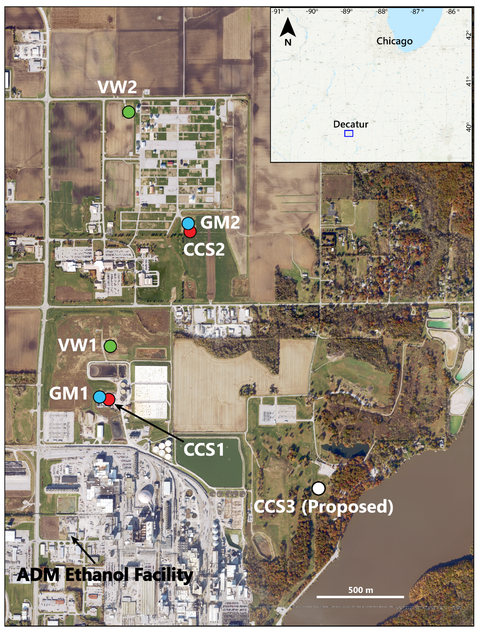
Building an updated reservoir model using available data, we evaluated the expansion of the current Area of Review (AOR) of the Decatur site in the Eastern Illinois Basin to approx. seven times by proposing to drill an additional Class VI injection well.
Figure 1 shows a map view of the Decatur injection site with the existing and proposed CO
2 injection wells and the ADM facility highlighted.
2. Geological Setting
The Illinois Basin is a cratonic basin in the Central United States covering an area of ∼155,000 km
2 (60,000 mi
2) [
10]. ISGS identified the brine-filled reservoir Mount Simon Sandstone for CO
2 storage at the Decatur site, which has been assessed to have a CO
2 storage potential ranging from 11 to 150 giga tonnes, as estimated by the United States Department of Energy (DOE) Carbon Atlas in 2012.
The Mount Simon Sandstone is a sedimentary unit of Cambrian age that extends to the states of Illinois, Western Kentucky, and Southwestern Indiana, and it is one of the most significant CO
2 storage reservoirs in the United States [
11]. The Mount Simon Sandstone lies above the Precambrian basement in a depth of around 5000 ft from ground level and has a thickness of up to 800 m within the Illinois state [
9,
12]. It hosts braided fluvial deposits near the base and marginal marine tidal bar sandstones towards the top [
9]. The average porosity of the Mount Simon Sandstone is computed to be 0.13 using wireline log data [
12]. However, the lower unit of the Mount Simon Sandstone, which is known as the Mount Simon Lower A formation, has been identified by the IBDP for CO
2 injection as having an average porosity of 0.22 and an average permeability of 200 mD [
11].
The Mount Simon Sandstone is overlain by the Eau Claire Shale that acts as a seal for CO
2 storage in the IBDP. In the Illinois Basin, the lower Eau Claire Shale consists of siltstones, shales, and sandstones that range from very fine- to fine-grained [
13,
14]. At the IBDP site, siltstone and shale dominate the lithology of the Eau Claire Shale in the lower part, with dolomitic limestone in the upper part. The thickness of the Eau Claire Shale varies from 61 m (200 ft) in Western Illinois to more than 370 m (1200 ft) in Southern Illinois. The effective porosity of the Eau Claire Shale is estimated to be in the range of 0.08 to 0.10 with a permeability of ∼1 mD [
14].
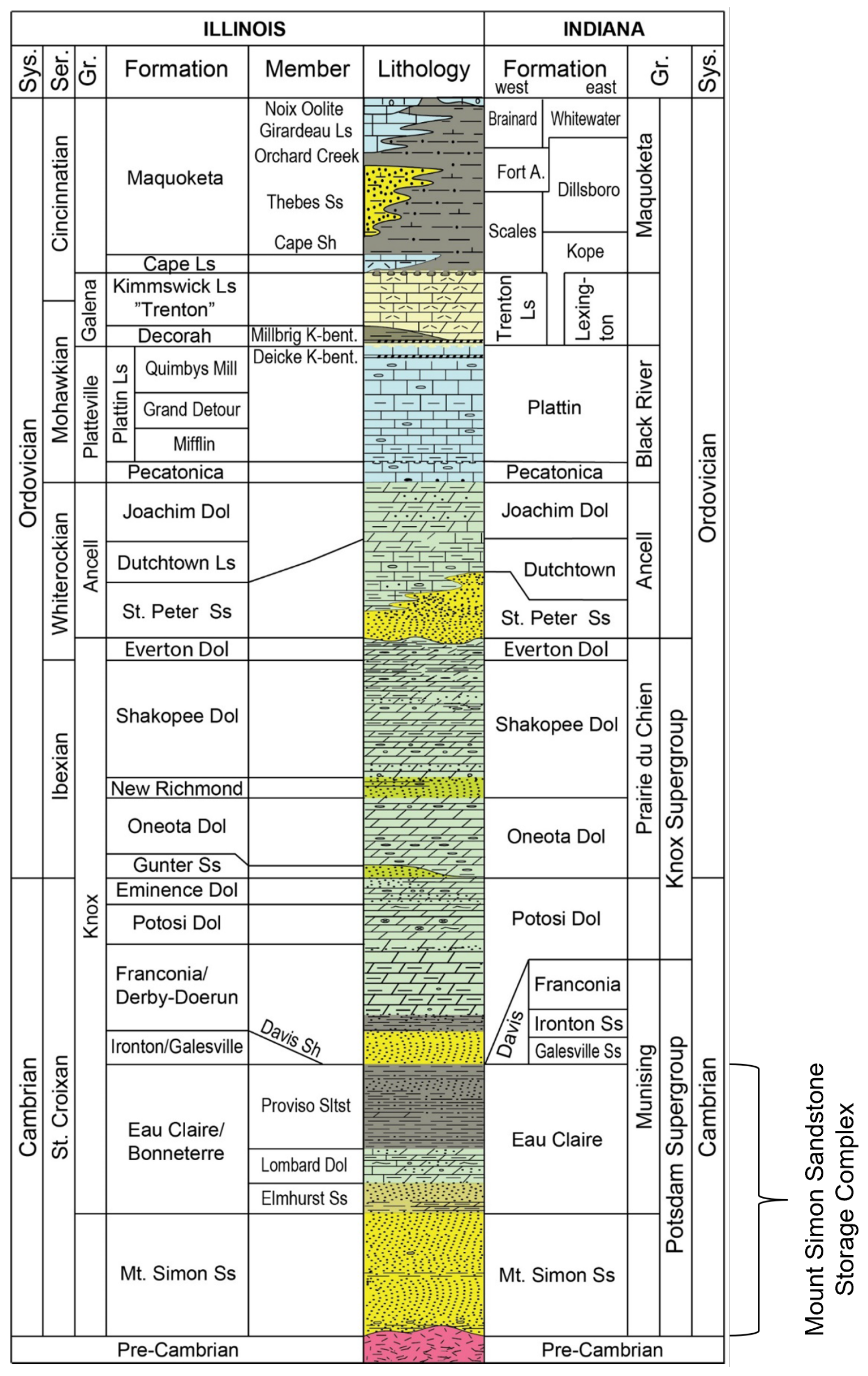
Figure 2 shows the stratigraphic column of the Cambro-Ordovician succession in Southern Illinois and Southwestern Indiana, highlighting the Mount Simon Sandstone storage complex that consists of the Mount Simon Sandstone formation as the CO
2 storage formation and the Eau Claire Shale overlying the Mount Simon Sandstone as the primary seal [
15].
3. Materials and Methodology
All geological and geophysical data that we used (wells and seismic) were made available by the Illinois State Geological Survey on the CO
2 DataShare website [
16].
3.1. Well Interpretation
We used well data from the IBDP and the IL-ICCS project. We used six wells: CCS1 (Injection Well 1), VW-1 (Verification Well 1), GM-1 (Geophone Monitoring Well 1), CCS2 (Injection Well 2), VW-2 (Verification Well 2), and GM-2 (Geophone Monitoring Well 2) (
Figure 1). CCS1, VW-1, and GM-1 were drilled by the IBDP and CCS2, VW-2, and GM-2 were drilled as a part of the IL-ICCS project.
We used gamma ray, bulk density, neutron porosity, resistivity, porosity, and permeability logs along with the available formation tops information from CO
2 DataShare to identify the Eau Claire Shale (seal) and Mount Simon Sandstone (reservoir) utilizing the available wells. The porosity of the Eau Claire Shale remained below 0.10, and the permeability varied from 0 to 10 mD. The porosity of the Mount Simon Sandstone varied from 0.12 to 0.30, and the permeability varied from 100 mD to 1000 mD. We identified the seal rock at a depth of ∼4700 ft and the reservoir rock within a depth range of ∼4900 ft to 6350 ft from the surface. All logs from CCS1 (
Figure 3) and CCS2 penetrate the seal and reservoir rocks; however, only porosity and permeability logs from the VW-1 and VW-2 well penetrated the seal and reservoir, and no logs from GM-1 and GM-2 intersected the seal and reservoir.
Selecting a CO2 injection interval is an important step for CO2 sequestration studies. Mount Simon Sandstone has been identified as a reservoir rock by the IBDP. However, there are intervals where the porosity and permeability are too low to be considered for injection. We characterized such intervals as baffles and defined a porosity of >0.15 and permeability of >20 mD as cutoffs to identify the CO2 storage interval. We identified the Mount Simon Sandstone Lower A for CO2 injection at a depth of ∼6250 ft from the surface.
3.2. Seismic Interpretation
We used 3D seismic data for interpretation that were acquired by the IBDP in January 2015 and reprocessed in 2019 to improve the resolution for interpreting geological features in the subsurface. The IBDP 3D seismic data are available as a depth-migrated seismic volume covering an area of ∼155,000,000 ft2 (∼14 km2) with 268 inlines and 2992 crosslines. The inlines and crosslines are spaced at an interval of 40 ft (∼12 m) and 5 ft (∼1.5 m), respectively. The sampling interval for the seismic volume is 2 ms.
To interpret different horizons on the seismic data, we first tied the CCS1 well to the depth-migrated seismic volume. We chose CCS1 for the well to seismic tie as all well logs from CCS1 intersected the seal and reservoir rocks. We identified the different formation tops on the seismic data consisting of the Eau Claire Shale (seal) and Mount Simon Sandstone units A to D (reservoir). We mapped all horizons within the survey area to extract 3D surfaces for developing the static and dynamic reservoir models. We also interpreted several faults from the seismic data that mostly consisted of normal faults indicating an extensional stress regime in the area.
We expanded the existing area of the IBDP seismic survey to approx. seven times that of the original AOR to model the CO2 plume migration during and after injecting ∼27 Mt of CO2 in the Mount Simon Sandstone, allowing enough area to model the evolution of the step-out plume. We expanded the AOR by increasing the size of the defined polygon for mapping the 3D surface from seismic data. All data from wells and seismic for the IBDP are available only for the original AOR. Expanding the AOR beyond the limits of the seismic survey, therefore, adds some uncertainty in the interpretation.
3.3. Static Reservoir Model
A static reservoir model was created using open-source well and seismic data to describe the storage complex properties.
3.3.1. Structural Modeling
The first step in structural modeling is fault modeling and pillar gridding. This serves as the skeletal framework of the 3D grid. Because the AOR is significantly expanded, we built a coarse grid with a cell size of 350 × 350 ft to keep the computational expense manageable. However, the grid cells around the wells were refined by subdividing the coarse grid cells, allowing a high resolution to capture the plume migration from injector wells. The surfaces and well tops of each formation were added to the grid to create a set of horizons. The top and base of each successive formation defined one zone with the exception of the Mount Simon Lower A formation, which was subdivided into three zones based on differences in permeability. The structural modeling process ends with subdividing each zone into layers. More layers were added to the reservoir intervals to increase the vertical resolution and better capture their heterogeneity. The final geologic model has 225 geological layers and 9,149,400 grid cells.
3.3.2. Net-to-Gross Log
We created a net-to-gross (NTG) log using porosity and permeability cutoff values of <0.15 and <20 mD, respectively, to differentiate between intervals that act as baffles from reservoir intervals. These values were based on earlier studies conducted by Schlumberger who applied these baffle facies to their model to overcome history-matching challenges [
17].
3.3.3. Well Log Upscaling
We upscaled the well logs to the layers in order to assign values to each cell that was penetrated by the wells used in the model. Facies logs were upscaled using the “most of” algorithm, as this honors the most representative value in the penetrated cells [
18,
19]. Porosity and permeability logs were upscaled using arithmetic and geometric methods, respectively [
18,
20,
21].
3.3.4. Property Modeling
We distributed discrete properties (NTG) using sequential indicator simulation and continuous properties (porosity and permeability) using sequential Gaussian simulation. We used a variogram analysis created by Zaluski and Lee [
17] to control the spatial distribution of the properties. The porosity model was used as a secondary co-kriging variable for the permeability model.
3.4. Reservoir Fluid Flow Simulation
The dynamic reservoir model was built from the static reservoir model by exporting key rock properties and well trajectories into a commercial compositional reservoir simulator (i.e., GEM 2022.10 by Computer Modelling Group Ltd., Calgary, AB, Canada (CMG)). The compositional reservoir simulator includes a framework to model carbon capture and storage (CCS) processes. Several considerations need to be addressed, including the reservoir modeling and simulation input parameters, reservoir boundary conditions, injection well data, trapping mechanisms, and dynamic scenarios. Our injection scenario added one additional injector well (CCS3) located down dip (south-east), which injected one mega tonne of CO2 per year for a duration of 20 years in a highly permeable zone with high injectivity. All injection wells were shut down after the injection period, which was followed by a migration period of 77 years at the end of CCS3 injection (Jan-2047). The simulation considered a total time of 100 years following the current active permit for CCS2, ending in 2024 (total simulation time was until Jan-2124).
3.4.1. Reservoir Simulation Input Parameters
The input parameters for the dynamic reservoir simulation model where obtained from the static reservoir model, from the literature [
22], and from reports regarding the modeling efforts by Schlumberger [
17] specifically for the IBDP. The most important general parameters are summarized in
Table 1.
The well data of CCS1 and CCS2 represent the actual parameters of the wells as these have been drilled and brought on injection already in the past. Only the well data for CCS3, which is the proposed additional well, was fabricated using feasible and representative values from typical CO
2 injector wells. The parameters for all three wells are summarized in
Table 2.
3.4.2. Boundary Conditions
Instead of the typical no-flow boundaries with cell size multipliers at the borders of the reservoir that are suggested in the literature [
17,
23], we extended the AOR in the static model and included an aquifer model allowing leakage out of the reservoir model boundaries by CO
2 displacing the brine acting on the grid edge and reservoir boundary. The modeling technique based on Fetkovich [
24] represents the real aquifer in the IBDP that is infinitely acting. Information about the outflux, i.e., how much brine the CO
2 injection process displaces, allows us to also consider the shift of the fresh water/brine contact towards the north of the system. The top and bottom of the reservoir are assumed as no-flow boundaries.
3.4.3. Buoyancy Trapping
One part of the trapping mechanisms is the buoyancy trapping, which we considered with the extension of the AOR and with the interpretation of reservoir rock features such as low permeability and porosity representing baffles that direct the CO2 laterally instead of barriers that stop fluid flow. The trapping occurs below the primary seal of the Eau Claire Shale, with baffles existing mainly in the Mount Simon C and D formations. Shallower zones than the Eau Claire Shale might represent secondary seals, but the interpretation of those is outside the scope of this research.
3.4.4. Capillary Trapping
Another mechanism of trapping CO
2 in the subsurface is capillary trapping, or residual trapping, where CO
2 is permanently stored as an immobile phase due to capillary forces. At this point, CO
2 has a relative permeability of zero incorporated in the relative permeability curves of water and gas. When CO
2 is injected into the reservoir, it first displaces the brine in a drainage process, and after injection, the brine as the wetting phase moves back to the pores in an imbibition process. This forms a hysteresis that can be used as a modeling approach for capillary trapping. In this study, we used the hysteresis modeling based on LAND [
25] for gas phase trapping. We modeled the relative permeability curves of liquid and gas (water and CO
2) with Brooks–Corey [
26] correlations based on Schlumberger lab data for the endpoint relative permeabilities [
17]. This modeling resulted in the relative permeability curves shown in
Figure 4.
We also implemented a linear hysteresis model with no distinction on the direction of the saturation change and with five curves for hysteresis plotting, shown in
Figure 4.
It is noted that the relative permeability curves and hysteresis modeling with CO2 trapping is an evolving field of study, as CO2 relative permeability is difficult to measure. Evolving methods involve digital rock physics (DRP) in modeling efforts coupled with laboratory measurements that are outside the scope of this work.
3.4.5. Solubility Trapping
As another and one of the most important trapping mechanisms of CO2 in the framework of CCS, we incorporated solubility trapping in the dynamic reservoir model. The solubility of CO2 in the brine depends, therefore, on the thermodynamic conditions of the reservoir and the salinity of the brine that is present. CMG GEM allows us to enter aqueous phase solubility data by specifying Henry’s constant H, the reference pressure, and the apparent molar volume of dissolved CO2 .
To calculate these input parameters, we used some correlations from the literature. Harvey [
27] developed a correlation for the calculation of Henry’s constant at the pure water saturation pressure (
), shown in Equation (
1).
where
is the water saturation pressure in kPa at a specific temperature
T in K;
is the reduced temperature of water defined by the ratio of the given temperature
T in K and the critical temperature of water
in K, equal to 647.14 K:
.
Thereby, we calculated the saturation pressure of water with the correlation by Saul and Wagner [
28], shown in Equation (
2).
where
is the critical pressure of water, equal to 22.064 × 10
3 kPa.
We computed the parameter
with the correlation according to Garcia [
29], shown in Equation (
3).
where
is the apparent molar volume of dissolved CO
2 in m
3/mol and the temperature
T in K.
We incorporated the salinity effect of brine compared with pure water using the correlation described by Bakker [
30], and it is shown in Equation (
4).
where
is Henry’s constant of CO
2 in the brine,
is Henry’s constant of CO
2 in the pure water,
is the salting-out coefficient of CO
2, and
is the molality of the dissolved salt in mol/(kg·H
2O).
We calculated the salting-out coefficient of CO
2 according to Equation (
5) [
30].
These calculations yield in the IBDP case of a constant reservoir temperature of 50 °C and 200,000 ppm NaCl in the brine the results summarized in
Table 3.
4. Results and Discussion
The variations in the NTG model are a result of porosity and permeability differences within the formations, indicative of differing depositional environments [
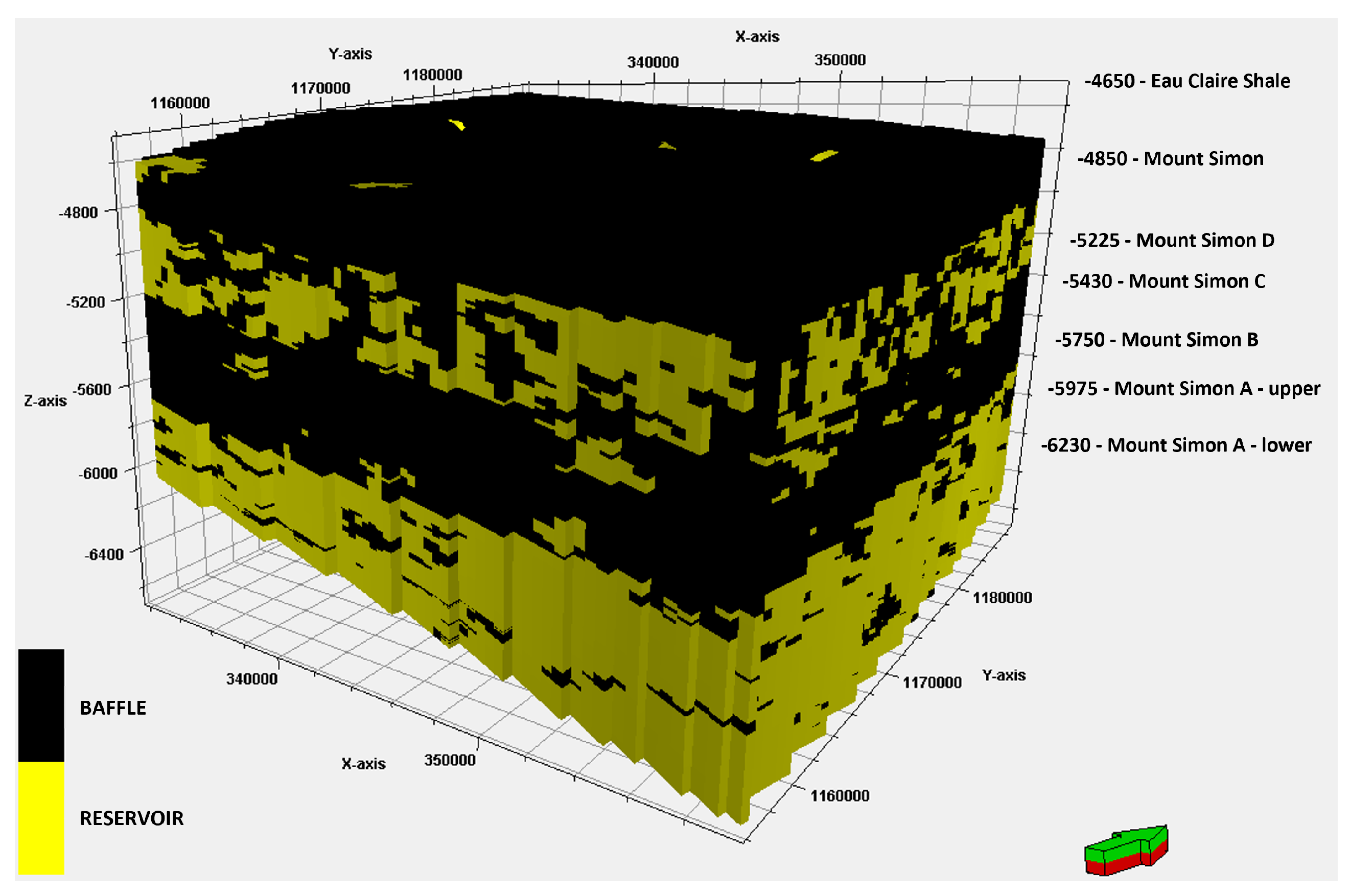
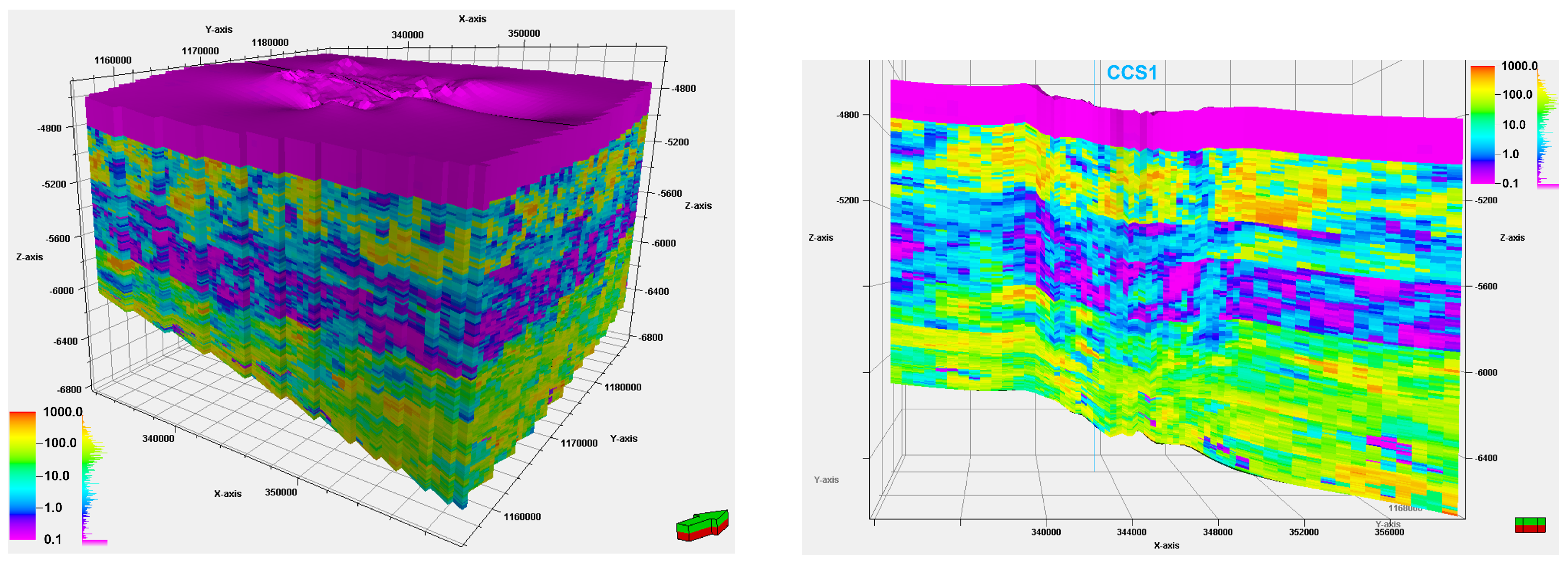
15]. At the top of the NTG model, we identify a baffle facies representing the Eau Claire Shale. This formation shows characteristic low porosity and low permeability. The Mount Simon Sandstone underlies the Eau Claire Shale. The quality of the sandstone varies from the top to the bottom of this sequence. The top of the Mount Simon Sandstone is the Upper Mount Simon Sandstone, with an almost equal distribution of reservoir and baffle facies. A low porosity and permeability Middle Mount Simon Sandstone formation underlies the Upper Mount Simon Sandstone. This unit is characterized predominantly by baffle facies. The base of the model shows the highly porous and permeable sandstone of the Lower Mount Simon Sandstone.
Figure 5 shows the NTG model in a 3D visualization of the model and highlights our interpreted baffles.
The amount of pore space available for CO
2 to be stored is largely controlled by the porosity of the formation [
31]. The base of the model shows the highly porous Lower Mount Simon Sandstone formation (Mount Simon A and B), which we identified as the target injection interval to utilize the large amount of pore space available for CO
2 storage. The porosity in this interval ranges from 0.10 to 0.30 with a value of 0.25 on average. The Lower Mount Simon Sandstone is overlain by the low-porosity Middle Mount Simon Sandstone (Mount Simon C and D), with the porosity ranging from 0.06 to 0.12 and a value of 0.09 on average within this interval. The Middle Mount Simon Sandstone is overlain by the Upper Mount Simon Sandstone (Mount Simon E) and has a porosity range of 0.05 to 0.15 with a value of 0.12 on average. The Mount Simon Sandstone sequence is capped by the Eau Claire Shale. This unit is characterized with a very low porosity, ranging from 0.02 to 0.10 with a value of 0.05 on average. The heterogeneity of the porosity model can be observed in the 3D model and through a cross-section (J-Slice) at the CCS1 well location in
Figure 6.
In general, more fluid can be produced or injected when the permeability is higher, which lowers the number of injection wells needed [
32]. Also, the injected CO
2 needs to be trapped by an impermeable seal to prevent leakage out of the containment area. The permeability of the Lower Mount Simon Sandstone, which is our target injection interval, is high with more than 100 mD on average. It is overlain by a low-permeability (13 mD on average) Middle Mount Simon Sandstone, which acts as baffles that impede the vertical flow of CO
2 and displace it laterally. The regional seal is provided by the highly impermeable Eau Claire Shale with a permeability of less than 5 mD on average. The 3D model and a cross-section (J-slice) of the permeability model through the CCS1 injection well is shown in
Figure 7.
The simulation results show that one additional injector well (CCS3) can achieve a high injection rate, adding a cumulative of 20 million metric tonnes of CO
2 to the IBDP without fracturing the reservoir in just 20 years. The bottomhole pressure of all wells reaches a maximum of 80% of the assumed fracture pressure, equivalent to a fracture gradient of 0.7 psi/ft [
33]. This is compliant with the regulatory threshold of maximum 90% of the fracture pressure.
Figure 8 shows the cumulative injection of CO
2 and the bottomhole pressures of the wells with the fracture pressure ceilings.
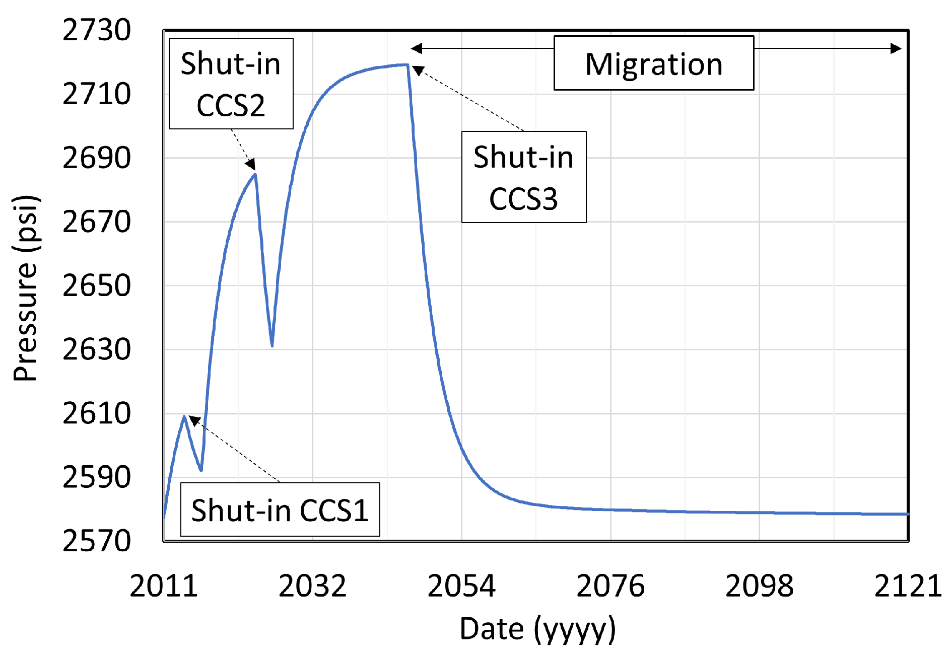
Injection periods add a maximum of 142 psi to the average reservoir pressure in the extended AOR, which is relieved and equilibrates during shut-in periods between the injections as well as in the 77-year migration period following injection (
Figure 9). This adds minimum stress to the reservoir itself that can be quantitatively investigated by geomechanics modeling, which is outside the scope of this study.
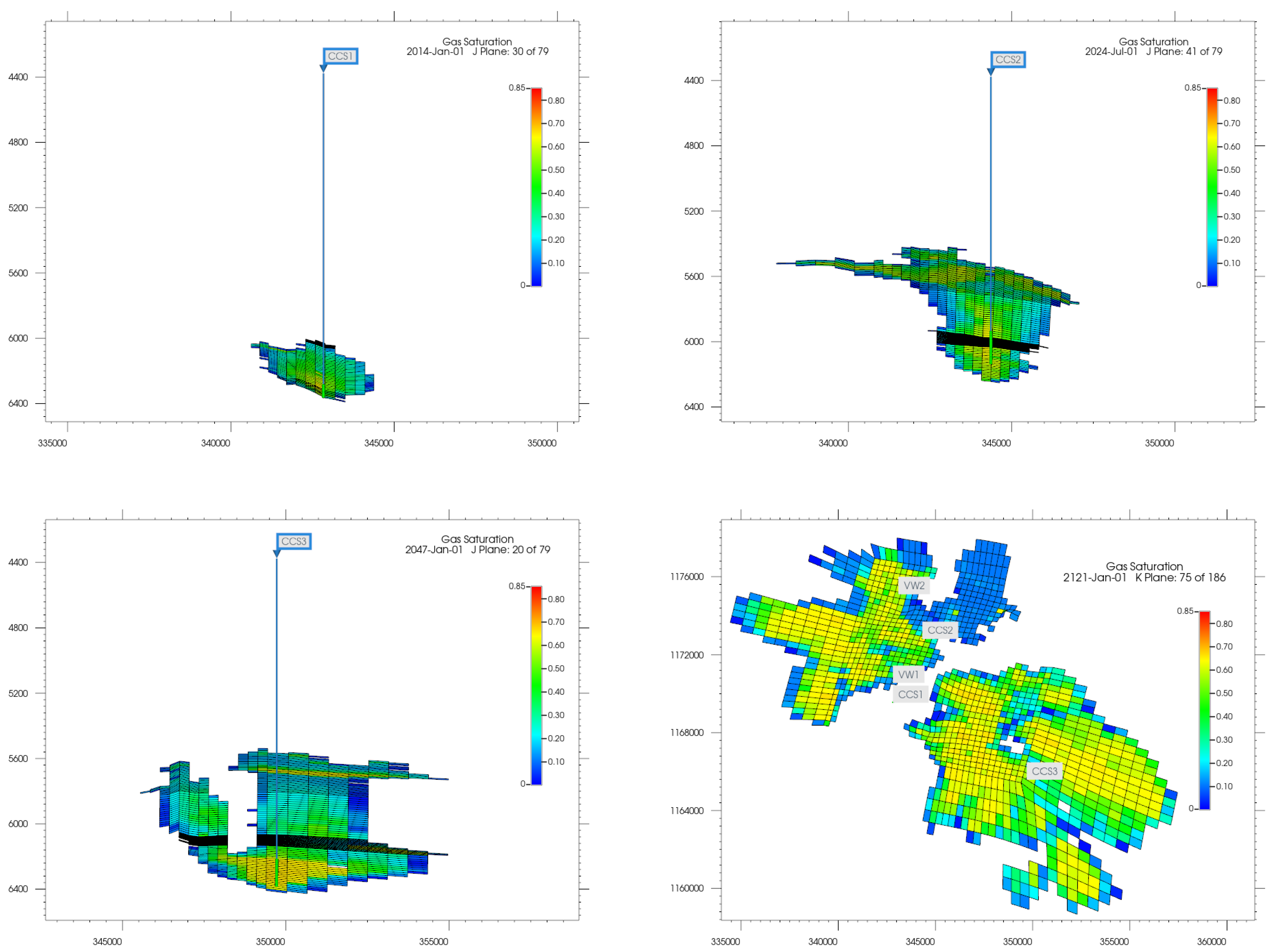
The plumes of the CCS1 and CCS2 wells interact with each other while the plume of the CCS3 well stays as a standalone one for the whole duration of the simulation. The shape of the plumes at the injection locations (perforations) and the maximum aerial extend are shown in
Figure 10. The maximum lateral extent of all plumes is less than an area of 5 × 4 miles.
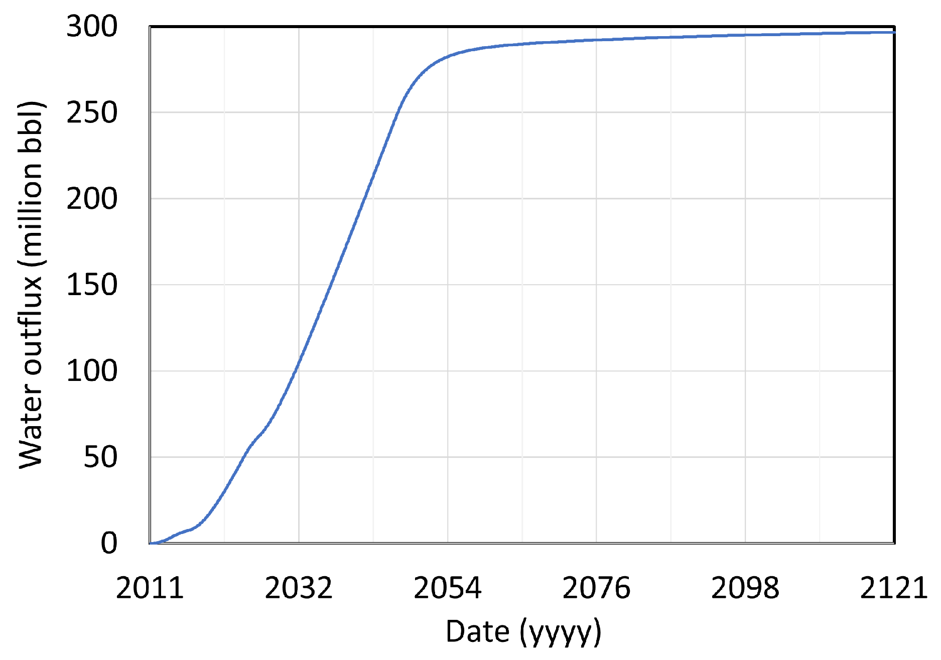
With the 27 mega tonnes of CO
2 that we are able to inject in this scenario, 297 million barrels of brine are displaced out of the AOR, as shown in
Figure 11.
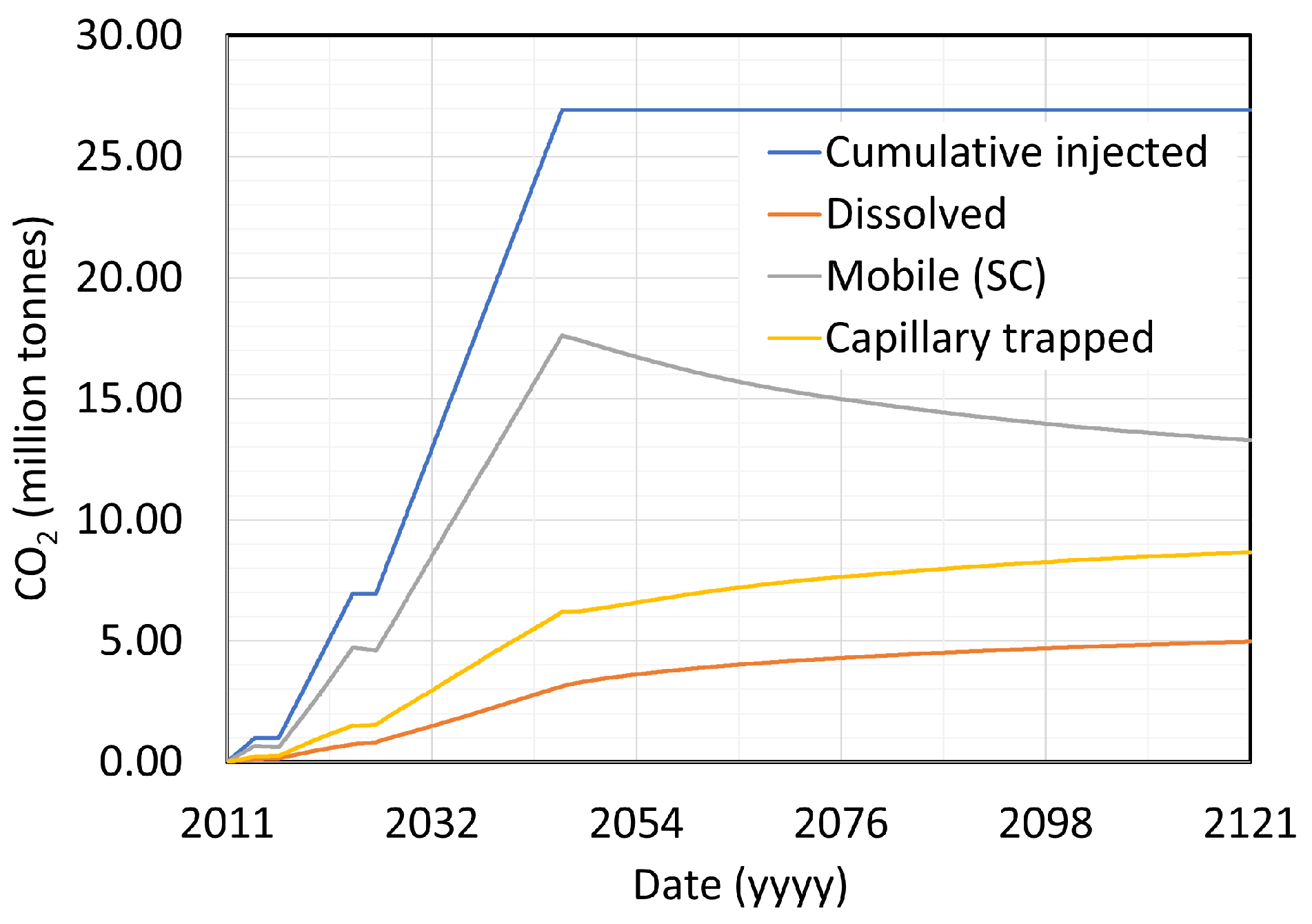
After the 77-year migration period and the end of the simulation, 49% of the injected CO
2 is still in the mobile (supercritical) phase, whereas 32% is capillary-trapped and 19% is dissolved in the brine.
Figure 12 shows the cumulative injection of CO
2 and the time evolution of the different trapping mechanisms.
Although CO2 sequestration in the framework of CCUS is a relatively recent technology in practice (∼14 years), the oil and gas industry has been safely performing CO2 injection in the framework of enhanced oil recovery (EOR) for several decades. Presented in this paper, the reservoir simulations provide valuable insights into the movement and changes in reservoir properties due to the upscaling of CO2 injection and can, therefore, add to a safe adoption and implementation of CCS. Our results show an areal containment of the CO2 plumes within 20 mi2 for at least 100 years, storing 27 Mt of CO2. This implies an areal need of 8150 to 110,000 mi2 to store the estimated 11 Gt to 150 Gt by the United States Department of Energy (DOE) Carbon Atlas in 2012 and thereby would extend to the whole Illinois Basin at the high estimate.
Uncertainties and Limitations
Our static reservoir model is limited with respect to the availability of the seismic survey. Moving beyond a certain point and out of the survey limits adds uncertainty to the reservoir model. Therefore, we expanded the AOR only to approx. seven times the current limit of the available seismic survey. The dynamic reservoir model is limited with respect to the size of the grid cells as more, i.e., smaller, grid blocks increase the computational expense and simulation time. Also, relative permeability measurements of CO2 are difficult to accomplish, which is why we have modeled the relative permeability curves of CO2 and water as part of the capillary trapping mechanism using correlations.
5. Measurement, Monitoring, and Verification Plan
An MMV plan addresses several important questions regarding the upscaled CCS project. Firstly, it enables the monitoring of the CO2 plume location, geometry, and movement direction through time-lapse monitoring, which helps to manage subsurface reservoir stress and prevent in situ fault reactivation. Additionally, pressure monitoring, including injection pressure, top seal pressure, and pore pressure, provides crucial information about the behavior of the CO2 plume and its interaction with the aquifer.
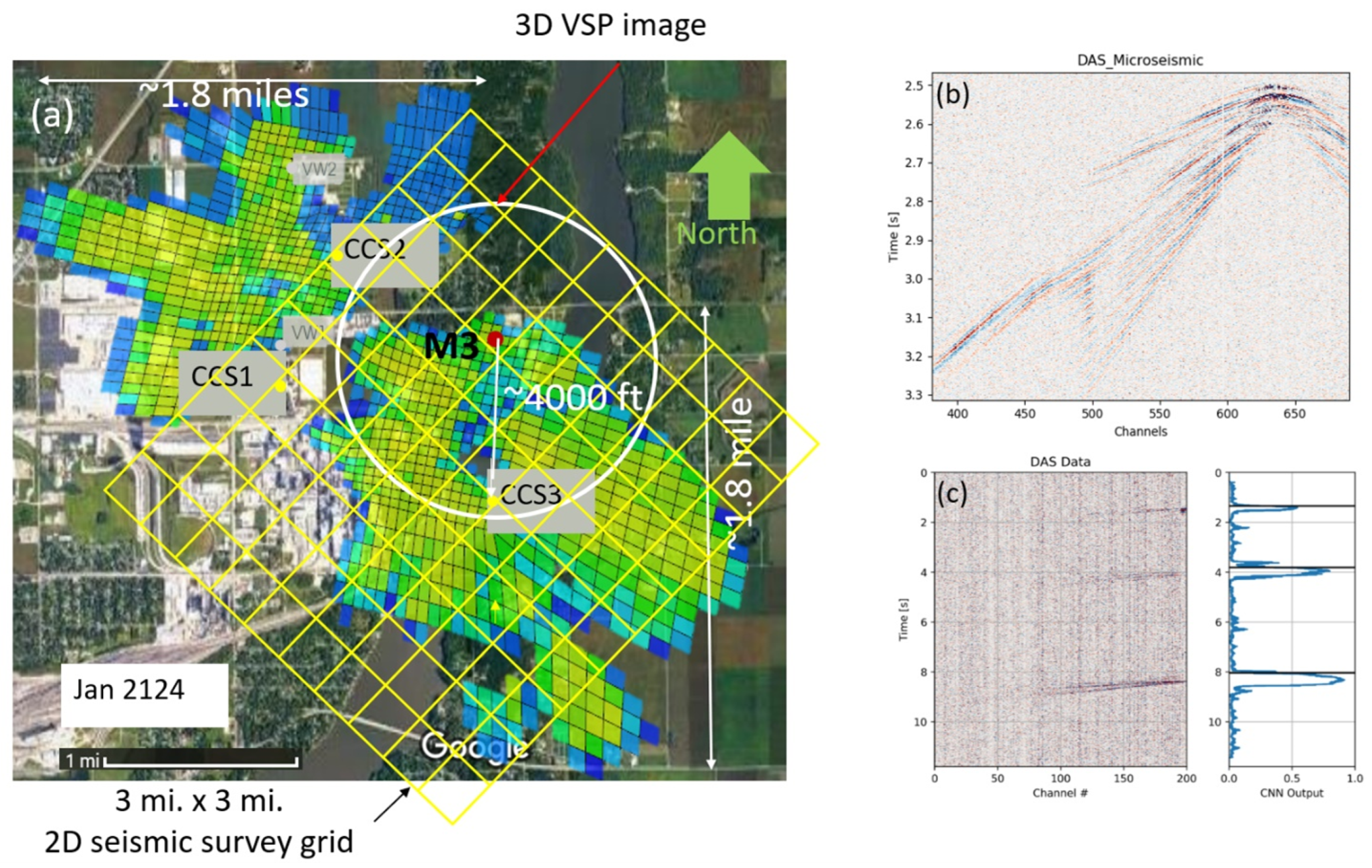
So far, the IBDP has performed atmospheric and shallow monitoring. To enhance the existing monitoring efforts, we propose expanding the current MMV plan by incorporating reservoir caprock and borehole monitoring. This includes measuring the pressure at the top seal of the reservoir to assess the impact of plume pressure. We suggest a step-by-step approach to data acquisition, starting with a 2D seismic survey over the new plume, followed by repeated 3D vertical seismic profiling (VSP) surveys in existing wells. The addition of a new monitor well in the proximity of the CCS3 plume area further improves pressure measurement accuracy and uncertainty estimation.
We approach our proposal step-by-step, starting from a low-cost and moving towards higher-cost data acquisition plans.
- (i)
We started with a 2D seismic survey over a new plume, as shown in
Figure 13a, and compared it with the existing baseline survey.
- (ii)
Next, we performed repeated 3D VSP surveys in the existing wells.
- (iii)
A little costlier will be a new monitor well M3, shown in
Figure 13a, in the proximity of the CCS3 plume area at an approximately 4000 ft radius. We directly measured pressure from this well apart from the measurement in the injection well. This will improve the uncertainty estimation in the measurement as we move away from the injection well. Currently, VSP is thought to be adding constraints for monitoring plume extent. There are challenges of repeatability because of surface conditions and imaging out to the edge of the injection plume; distributed acoustic sensing (DAS) VSP may be better in this case.
- (iv)
Monitor wells have been used for shallow monitoring, mostly for leakage. Microseismic monitoring, especially DAS microseismic monitoring, as shown in
Figure 13b, shows the scope of detecting additional weak microseismic events as compared with the current microseismic monitoring. The current seismicity of the IBDP site is small and indicated most micro-earthquakes occurring at depths greater than 2.2 km that likely do not compromise the integrity of the seal [
34]. We would anticipate that similar behavior for any additional injection wells and microseismic monitoring should be included in any future use and development of this site. The current microseismic monitoring results quantify the control in terms of preferred movement of stress with respect to the shale baffles. Application of artificial intelligence (AI) such as deep learning for automatic detection of events as shown in
Figure 13c clearly shows the possibility of the near-real-time detection of much weaker additional events that would not have been possible by the current industry practices, such as short-term average/long-term average (STA/LTA) for the auto-detection of weak-motion seismology [
35]. The latest machine learning approaches allow for automated monitoring with greater confidence than in the past, as demonstrated by Mousavi et al. [
36]. This has significant implications on real-time injection decisions and operation costs. In addition to deep learning for auto-detection, 3D inversion for properties, such as porosity from inversion, has been proven by existing IBDP research as useful for extrapolating porosity/baffles away from wells. Improvement of the reservoir properties such as porosity with better inversion of the pre-stack data may aid more accurate interpretations. Other monitoring technologies that could be used as insurance are electromagnetics and interferometric synthetic aperture radar (InSAR) data to measure ground deformation.
Figure 13.
(
a) Top view of the two plume dimensions overlain on the satellite map of the area of interest. The location of the proposed well CCS3 is shown in a yellow dot. The red dot shows the location of the monitor well M3 with an aperture radius of around 4000 ft from the CCS3 well. The yellow grid shows the 3 miles by 3 miles 2D seismic survey grid. (
b) Example of the advantage of monitoring microseismic activities with distributed fiber optic sensing (DAS) such as high-resolution images facilitating enhanced visualization of waveform features [
35]. (
c) An example of a deep learning application for the automated identification of weak-motion seismology, which enables the identification of additional events in time and consequently in space.
6. Conclusions
We present an integrated assessment workflow for upscaling CO2 storage in the Eastern Illinois Basin and develop a reservoir model from both a static and dynamic perspective with publicly available data. We expand the AOR, including the ICCS project and IBDP open source data. This allows us to increase the 20-year cumulative storage of CO2 from 7 million metric tonnes with the existing two injectors to 27 million metric tonnes, proposing one additional injector well to the southeast of the AOR. Thereby, we show a 100-year containment within a 5 × 4 mile area, reduce the risk of fault activation by keeping the average reservoir pressure increase at a maximum of 142 psi, and stay below the legal bottomhole pressure threshold of maximum 90% of the fracture pressure at the perforations.
We further elaborate on the implementation of an MMV plan incorporating reservoir caprock and borehole monitoring, along with seismic, microseismic, and geodetic techniques, to be essential for the effective upscaling of CO2 injection in CCS projects. These monitoring technologies, coupled with advancements in artificial intelligence, have the potential to provide valuable insights into the behavior of CO2 plumes, improve operational decision making, and ensure the long-term sustainability and safety of upscaled CCS projects. Further research and technological advancements are warranted to refine and optimize the proposed MMV plan for future implementation.
Future Work
From a modeling and simulation perspective, future work needs to include the modeling and experimental validation of the CO2 relative permeability hysteresis, as the residual trapping mechanism accounts for the most important one. Also, modeling the long-term effects (several thousands of years) and incorporating the mineral trapping mechanism would be of interest. To best ensure a containment of the CO2 without altering the reservoir properties too much, i.e., fracturing the reservoir or triggering the faulting system, a geomechanical modeling approach should be included, especially in the vicinity of the primary seal (Eau Claire Shale), as the CO2 will reach this ceiling eventually due to the density difference of CO2 and brine. In this work, the interpreted faulting system has been incorporated for geometry purposes but faults have not been assigned specific properties, such as representing pathways or baffles and barriers to fluid flow. This should be accounted for in future work.
As a part of future work, we can use our reservoir model as a reference for underground natural gas storage, CO
2 injection in coal reservoirs, and enhanced oil recovery [
37,
38,
39,
40].
