Article

Multiple Factors Coupling Probability Calculation Model of Transmission Line Ice-Shedding

1
Joint Laboratory of Power Remote Sensing Technology, Electric Power Research Institute, Yunnan Power Grid Company Ltd., Kunming 650217, China
2
Zhaotong Power Supply Bureau of Yunnan Power Grid Co., Ltd., Zhaotong 657000, China
3
School of Civil and Hydraulic Engineering, Huazhong University of Science and Technology, Wuhan 430074, China
*
Author to whom correspondence should be addressed.
Energies 2024, 17(5), 1208; https://doi.org/10.3390/en17051208
Submission received: 21 December 2023 / Revised: 2 February 2024 / Accepted: 28 February 2024 / Published: 3 March 2024
(This article belongs to the Section F: Electrical Engineering)

Abstract

:
After a transmission line is covered by ice in winter, ice-shedding and vibration occurs under special meteorological and external dynamic conditions, which leads to intense transmission line shaking. Transmission line ice-shedding and vibration often cause line flashover trips and outages. In January 2018, three 500 kV transmission lines, namely, the 500 kV Guanli line, the 500 kV Dushan line, and the 500 kV Guanqiao line, tripped and cut off due to ice-shedding and vibration in Anhui province, seriously threatening the safe operation of a large power grid. Current studies mainly focus on analyzing the influence factors and characteristics of line ice-shedding and investigating suppression measures, but they only analyze the correlation between each influencing factor and icing or shedding, and do not consider the coupling effects between multiple factors. In this paper, the key influencing factors and the probability distribution of transmission line ice-shedding were analyzed, and a multiple-factor coupling fault probability calculation model of line ice-shedding based on Copula function was proposed. The fault probability was calculated directly by considering multiple influence factors at the same time, which effectively overcame the error caused by multi-factor transformation in fuzzy membership degree and other methods. It provided an important decision-making basis for preventing and controlling transmission line ice-shedding faults.

1. Introduction

Icing in winter is a major disaster affecting the normal operation of transmission lines. In 2008, southern China suffered the most serious ice disaster in history. Among the damages, the loss of the Yunnan power grid was the most serious, with a direct economic loss of more than 10 billion yuan [1]. In recent years, with extreme global climate change, large-scale icing disasters have occurred frequently. In January 2018, three 500 kV transmission lines, namely, the 500 kV Guanli line, the 500 kV Dushan line, and the 500 kV Guanqiao line, tripped and cut off due to ice-shedding and vibration in Anhui province, seriously threatening the safe operation of a large power grid.
Current research mainly focuses on analyzing the influence factors and amplitude characteristics of line ice-shedding and investigating suppression measures.
In terms of analyzing the influencing factors of ice accretion and shedding on transmission lines, Savadjiev and Farzaneh [2] analyzed and compared the statistical distributions of icing rate, temperature, wind speed, wind direction, relative humidity, and total ice accumulation between different icing regimes and phases. They further proposed an additive model in 2004 to describe the relationship between icing rate and the accompanying meteorological conditions [3], which statistically correlates each factor with the icing rate. Wagner [4] developed a numerical model to simulate ice accretion on conductor bundles by considering the bundle geometry and interactions between multiple conductors, and analyzed the influences of wind speed, conductor diameter, conductor surface temperature, etc. on the ice accretion shape and mass. Savadjiev and Farzaneh [3] developed a statistical model that combines extreme ice thickness with moderate wind speed during icing events, and they established Weibull, Gumbel, and empirical distributions to model hourly wind speeds, annual wind maxima, wind during icing, ice persistency periods, and ice thicknesses based on statistical analysis of meteorological data. Although these studies analyzed the probability of key factors affecting transmission line icing and shedding, they did not consider the coupling effects between multiple factors.
In the dynamic simulation analysis of transmission line ice-shedding, Hou et al. [5] developed a 3 degree of freedom (DOF) multi-level wire model suitable for analyzing transmission line ice-shedding and obtained its time response characteristics. Liang [6] studied transmission line ice-shedding under six ice-shedding rates and wind speeds. Wu [7] proposed a theoretical algorithm for the maximum ice-shedding and vibration height of transmission lines. Zhao et al. [8] studied the dynamic response characteristics of transmission line ice-shedding using finite-element numerical simulation and fitted a simplified formula for ice-shedding and vibration height of transmission lines considering the influence of multiple parameters with a large number of data points. Xu [9] developed a finite-element model of a tower line coupling system and analyzed the dynamic response characteristics of transmission line ice-shedding. Yan et al. [10] analyzed transmission line ice-shedding and vibration amplitude under different wind speeds, spans, heights, insulator string lengths, numbers of tension sections, and other parameters. Deng [11] used a finite-element numerical simulation method to systematically study the unbalanced tension of ice-shedding. Long [12] studied the coupling vibration characteristics of overhead transmission lines and the dynamic response characteristics caused by ice-shedding. Li et al. [13] proposed a three-dimensional motion capture system to investigate the dynamic response of transmission lines following ice-shedding and compare with the simulation results of the mathematical model. Ye et al. [14] simulated the influence of transmission line deicing on the tension of transmission line and the stress of fittings. Li et al. [15] established the finite element model of the two-tower three-line system using the commercial ANSYS 16.0 finite element software, and analyzed the force characteristics of the tower line under ice-shedding. Huang et al. [16], Lou et al. [17], Li and Wu [18], and Huang et al. [19] carried out reduced-scale modelling tests on the dynamic response of isolated span conductors under different kinds of ice-shedding conditions.
In a study of amplitude characteristic analysis and ice-shedding restraining measures, based on the non-linear simulation model of a 3-DOF multi-level conductor insulator system independently developed by Tsinghua University, Wang et al. [20] analyzed the dynamic mechanical ice-shedding characteristics of a 1000 kV ultra-high voltage (UHV) AC double-circuit transmission line on the same tower and proposed a scheme to suppress ice-shedding vibrations with phase-to-phase spacers. Xie et al. [21] proposed a two-node isoparametric truss element finite element model to simulate the dynamic process of progressive ice-shedding (PIS), which can consider the mass variation of ice and dynamic force variation on the remaining ice. And the proposed method was validated through small-scale and full-scale experimental results, which showed it is more accurate than existing methods assuming constant ice-shedding speed. Some researchers have proposed an optimal layout scheme for devices such as phase-to-phase spacers and double-layer viscoelastic lead-core dampers. Yang et al. [22] developed a three-dimensional finite element model of a tower-conductor-ground wire-insulator- interphase spacer system to identify the optimal arrangement for mitigating ice-shedding. Li et al. [23] and Yin et al. [24] analyzed the suppression effects of different damper arrangements on the ice-shedding galloping of transmission lines. Huang [25] designed and manufactured a transmission tower line test model, and carried out a variety of working condition ice-shedding galloping tests, which verified the effectiveness of the application of collision-type anti-vibration hammers in reducing the vibration of transmission line ice-shedding. Song [26] established a three-dimensional finite element model of the tower line system based on ABAQUS 6.6 software, and carried out an analysis study on the characteristics of transmission line breakage and de-icing, as well as related vibration control studies.
Due to the fact that transmission line icing or shedding is an event formed by the combined influence of various factors, existing studies have analyzed the key factors affecting transmission line icing or shedding, but they only analyze the correlation between each influencing factor and icing or shedding, and do not consider the coupling effects between multiple factors. Therefore, this paper analyzed the key influence factors and their probability distribution of transmission line ice-shedding, and proposed a multiple-factor coupling fault probability calculation model of transmission line ice-shedding to consider the coupling effect of multiple factors on the ice-shedding of transmission lines. The fault probability was calculated directly by considering multiple influence factors at the same time, which effectively overcame the error caused by multiple factor transformation in fuzzy membership degree and other methods. It provided an important decision-making basis for preventing and controlling transmission line ice-shedding faults.

2. Materials and Methods

2.1. Definition of Transmission Line Ice-Shedding

After a conductor is covered by ice in winter, the elastic potential energy on the conductor increases at greater icing amounts. Under the action of temperature rise, wind force increase, or mechanical external force, it is easy to de-ice a whole piece of equipment or different positions on the same equipment. At this time, the original elastic potential energy on the wire will be quickly converted into kinetic and potential energy, and the wire will bounce up in a half-wave shape. With the continuous exchange of energy, the conductor fluctuates up and down in the form of a standing wave, which results in continuous jumping of the line. This phenomenon is called transmission line ice-shedding. Due to the restrictions of air resistance, strand friction, and the inertial force of the insulator string swing, the jump amplitude will decrease rapidly and finally reach a stable state under the new condition. The duration of ice-shedding is usually only a few minutes, but the energy involved is huge and can easily cause transmission line flashover trips and power failures.
Transmission line ice-shedding is not only related to internal factors such as the mechanical and electrical characteristics of conductors and the type of icing, but is also related to external factors such as environmental parameters and external forces. There are three typical mechanisms of transmission line ice-shedding: (1) ice-shedding due to melting, (2) ice-shedding caused by mechanical ice breakage, and (3) ice-shedding caused by ice sublimation.
(1) Ice-shedding due to melting
There are two types of ice-shedding due to melting:
(a) With the increase of ambient temperature, the melting speed of ice coating at the interface between ice coating and conductor is faster than freezing speed. Thus, a liquid layer is formed between the conductor and the icing contact surface. The adhesion between the ice and the wire is reduced, resulting in ice-shedding. This type of ice-shedding can easily lead to a jump of the transmission line.
(b) The increase of the external environment temperature is more than 0 °C, which leads to the melting of the icing on the conductor. It is not easy to cause ice-shedding when only the external ice is melting. However, under this condition, the ice melting will occur in the inner part of the conductor which is in contact with the icing, and it is easy to cause ice-shedding.
(c) Solar radiation also has a certain impact on the icing of transmission lines. According to existing research, in the same region and season, generally speaking, the stronger the solar radiation, the higher the temperature. In addition, the contact area between conventional transmission lines and air is small, and the absorption capacity for short-wave and long-wave radiation is very weak. Taking the 500 kV transmission line as an example, the typical conductor type is 4×LGJ-400/35, and the diameter of a single conductor is about 26.8 mm, and 4 of them are about 107.2 mm. According to the calculation method of Wu and Xu [27], the solar radiation intensity in Yunnan in winter is S = 180 W/m2. According to the literature Zhang [28], the formula for calculating the power of solar radiation absorbed by transmission lines is:
W r z = α D S
where Wrz represents the power absorbed by the transmission line per unit length, in W/m; α is the emissivity of the conductor surface, generally taken as 0.48; D is the conductor diameter, in m; and S is the solar radiation intensity, in W/m2.
Using the above formula, the power absorbed by the transmission line per unit length can be calculated to be approximately 8.64 W/m. However, under rated current conditions, the heat generation power of the LGJ-400/35 line is 2560 W/m. Compared with the heat generation power, the power absorbed by the transmission line from solar radiation can be ignored. Therefore, in this study, the influence of solar radiation is mainly reflected in the temperature element, and additionally adding the influence of the radiation element on the results should be small, and the influence of solar radiation is not considered in this study for the time being.
(2) Ice-shedding caused by mechanical ice breaking
Mechanical ice breaking is mainly caused by external mechanical force or anti icing technology. Mechanical ice breaking may be caused by static load, such as bending, torsion, tension, etc., or by dynamic load, such as wind, vibration, knocking, etc.
(3) Ice-shedding caused by ice sublimation
Sublimation deicing means that the icing on the conductor changes from solid state to gaseous state directly below 0 °C, which mainly occurs at the interface between icing and air. The speed of sublimation deicing is slow, so it is not easy to cause deicing jump. This type of deicing is not considered in this paper.

2.2. Analysis of Key Factors Influencing Ice-Shedding on Transmission Lines

2.2.1. Ice and Icing Prediction on Transmission Lines

Transmission line icing is one of the necessary conditions for ice-shedding and vibration. Ice-shedding and vibration usually occur when the conductor is seriously iced.
The State Kay Laboratory of Disaster Prevention and Reduction for Power Grid Transmission and Distribution Equipment developed a numerical prediction system for transmission line icing. The system uses the scale of 3 km × 3 km in China and 30 m in local micro-terrain areas to forecast icing thickness on transmission lines [29]. In this system, the icing prediction model considers the influence of multiple factors such as current, wind speed, and temperature. The detailed details of the model can be found in the reference Lu et al. [30]. Therefore, the influence of the conductor current has been considered when calculating the ice-shedding in this study. The system has successfully predicted 39 power grid icing events of the State Grid Corporation of China in the last 10 years, especially, in 2018, the most serious power grid icing event in southern China since 2008. According to icing prediction results, the Yunnan power grid deployed ice melting measures in advance and carried out line ice melting in time. There was no ice tower collapse or line break accident on 220 kV and above lines. The icing thickness predictions of the system are shown in Figure 1.

2.2.2. External Environmental Factors

In addition to wind, the external environmental factors that cause ice-shedding include temperature and mechanical force. Vibration from wind, rising temperature, and the action of external mechanical force may make the ice on the conductor fall off partially or completely, causing ice-shedding and vibration. The faster the temperature rises, the greater the effect of wind and mechanical forces, and the more easily ice-shedding occurs.

2.2.3. Transmission Line Flashover Faults Caused by Ice-Shedding

When the jump amplitude makes the phase-to-phase or phase-to-ground distance of a transmission line less than a certain range, a phase-to-phase short circuit or conductor-to-ground discharge will occur. This causes transmission line flashover trips and power failures. This paper focuses on analyzing flashover faults caused by ice-shedding on transmission lines.

3. Probability Calculation Model of Transmission Line Ice-Shedding

3.1. Marginal Probability Distribution of Influence Factors on Transmission Line Ice-Shedding

(1) Calculating the marginal cumulative probability distribution of the “wind speed” key factor in ice-shedding
Wind is one of the key factors leading to ice-shedding. High wind speed is more likely to lead to mechanical ice breakage, whereas melting and deicing mostly occur under wind speeds of less than 10 m/s.
According to observed historical wind speed data under ice-shedding conditions, the marginal cumulative probability distribution of wind speed under ice-shedding conditions can be calculated as follows:
F W ( w ) = P ( W w )
where FW(w) is the marginal cumulative probability distribution of wind speed; W is the wind-speed variable; and w is the known value of wind speed.
The Gaussian kernel density estimation method is used to calculate marginal cumulative probability distribution of wind speed. And this method has been integrated into the “ksdensity” function in MATLAB 2016 [31].
(2) Calculating the marginal cumulative probability distribution of the “temperature” key factor in ice-shedding
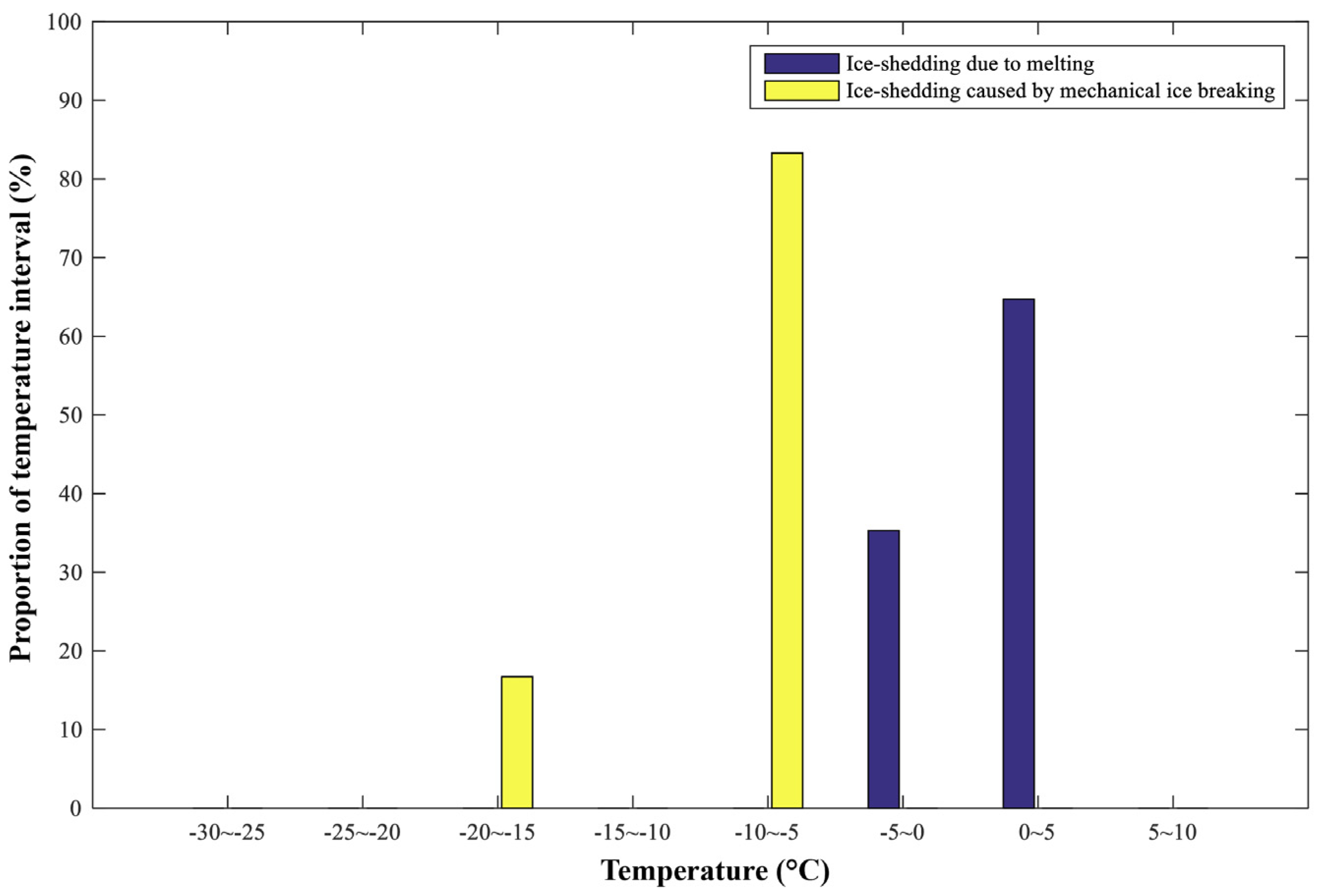
Air temperature is one of the key factors leading to ice-shedding. It has been found that deicing by melting mainly occurs above −5 °C, whereas mechanical deicing mainly occurs below −5 °C.
According to historical observed air-temperature data under ice-shedding conditions, the marginal cumulative probability distribution of air temperature under ice-shedding conditions can be calculated as follows:
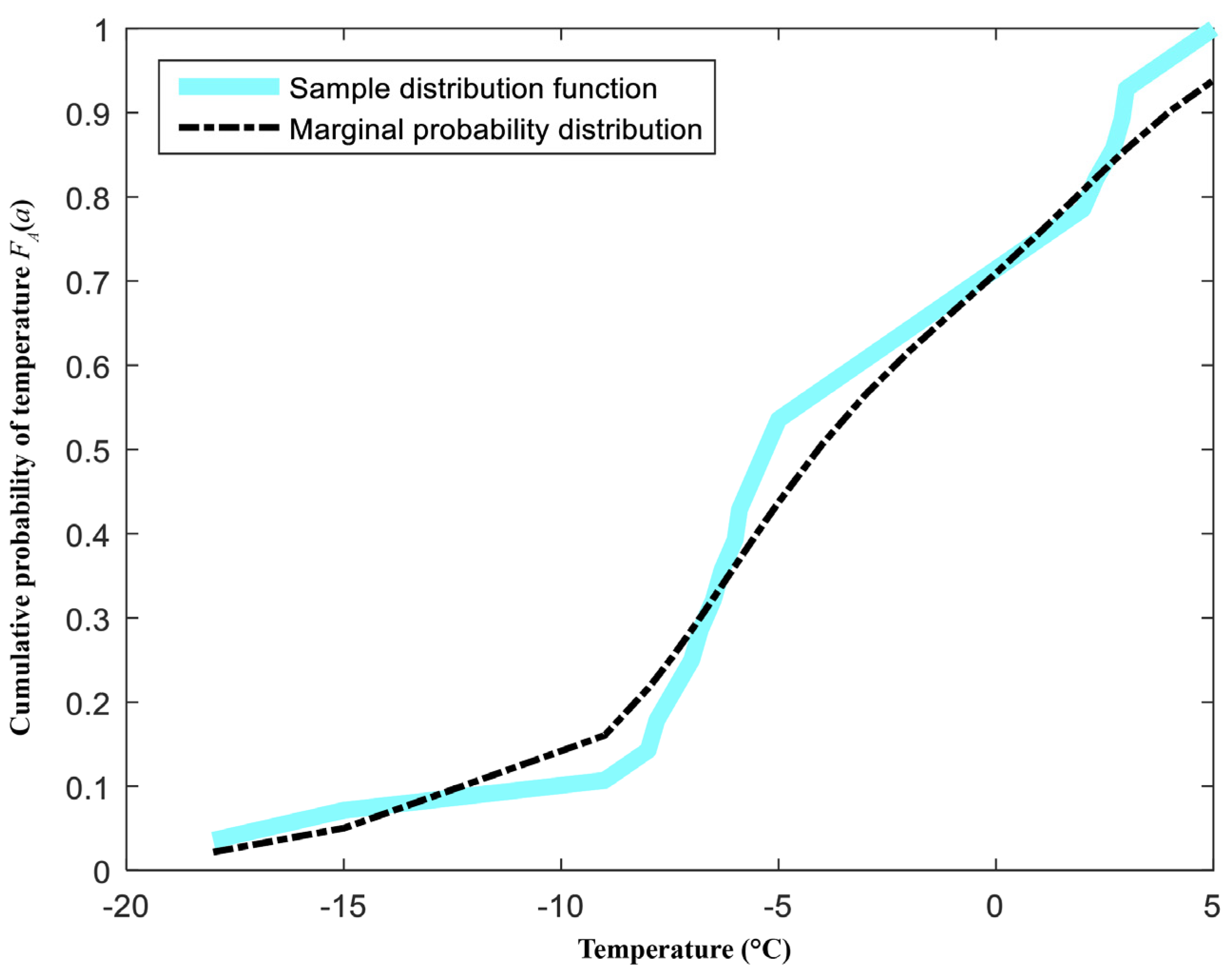
F A ( a ) = P ( A a )
where FA(a) is the marginal cumulative probability distribution of air temperature; A is the temperature variable; a is the current air temperature.
The Gaussian kernel density estimation method is used to calculate marginal cumulative probability distribution of temperature. And this method has been integrated into the “ksdensity” function in MATLAB.

3.2. Calculation of Multiple-Factor Joint Cumulative Probability Distribution of Transmission Line Ice-Shedding

According to the marginal cumulative probability distribution calculated in Section 3.1, the Copula function was used to calculate the joint probability distribution of the multiple-factor transmission line ice-shedding model, as follows:
F ( w , a ) = C ( F W ( w ) , F A ( a ) )
where F(w, a) is the joint cumulative probability distribution of multiple factors of transmission line ice-shedding; C( ) denotes the Copula function.
There are many kinds of Copula functions, including the elliptic Copula function and the Archimedean Copula function. Among these, the Archimedean Copula function is widely used, and the three most commonly used Archimedean Copula functions are the Gumbel Copula function, the Clayton Copula function, and the Frank Copula function. The Clayton and Gumbel Copula functions can only describe non-negative correlations between variables, whereas the Frank Copula function can describe negative correlation between variables. For more details about Copula functions, readers can be referred to Nelsen [32].
The correlation coefficient between the key influence factors may be negative. Thus, the Frank function is suitable for this research.
In the Frank Copula function, the Copula function parameter θ between two variables is first calculated. The maximum likelihood estimation is used to calculate the Copula function parameter θ. By substituting the calculated θ into the following formula, the joint cumulative probability distribution function of temperature and wind speed can be obtained. If the marginal cumulative probability values of temperature and wind speed are given, the joint cumulative probability value can be calculated.
C ( u , t ) = 1 θ ln 1 + e θ u 1 e θ t 1 e θ 1
where C(u, t) represents the multiple-factor joint cumulative probability, θ is the parameter of Copula, u represents the value of wind speed in the marginal cumulative probability distribution, and t represents the value of temperature in the marginal cumulative probability distribution.

3.3. Calculation of Transmission Line Ice-Shedding Failure Probability

The probability of ice-shedding will be calculated in Section 3.2 of this paper. The probability can be used to assess the possibility of ice-shedding. In this paper, we have collected ice-shedding observation data from the past 10 years. All the ice-shedding events are based on the actual observed ice-shedding events. Based on these observation data, a multivariate correlation between ice-shedding and factors such as wind speed and temperature is established, so as to obtain the specific parameters of the model in Section 3.2. Then, a calculation procedure for transmission line ice-shedding fault probability is proposed. It is compared whether these calculated probabilities are consistent with the actual situation. The details are as follows:
(1) Calculating the critical icing thickness for transmission line ice-shedding flashover
In this paper, the formula given in reference [33] was used to calculate the height of the transmission line de-icing jump. Assuming 100% de-icing of a transmission line, the icing thickness of a 500 kV conductor when the maximum amplitude of the de-icing jump exceeds 5 m and a 220 kV conductor when the maximum amplitude of the de-icing jump exceeds 3 m is the critical icing thickness for transmission line ice-shedding flashover:
H = Δ f × ( 2000 l ) × 10 3
where Δf is the sag difference of the conductor before and after ice-shedding and l is the span of the conductor.
(2) According to the predicted results for icing thickness of transmission lines, it was evaluated whether the actual icing thickness exceeded the critical icing thickness for deicing jump flashover. If so, the next step of the ice-shedding probability calculation was carried out; otherwise, it was not necessary to calculate the ice-shedding probability.
(3) According to Section 3.2, the multiple-factor joint cumulative probability distribution of transmission line ice-shedding was obtained. Given the observed wind speed and air temperature, the probability of transmission line ice-shedding was calculated.

4. Case Study

4.1. Study Area and Data Sources

This study considered icing of the Yunnan power grid in winter as an example. Yunnan is located in southwestern China. Because of its special horseshoe shape that is open to the north, cold air can easily cause large-area and long-duration ice-cover disasters in the Yunnan power grid. The data in this paper are observed ice-shedding data for the Yunnan power grid in the last 10 years, observed data from an outdoor natural disaster test field, and simulated test data from an artificial climate simulation laboratory. As Yunnan province is located in a high-altitude area and transmission lines have to pass through a large number of high-altitude mountainous areas, the wind speed at the location of the transmission lines can be quite high, with instantaneous wind speeds reaching around 60 m/s under extreme conditions. For example, during the icing period in 2018, we observed an instantaneous wind speed of 62 m/s at an outdoor natural disaster testing site. Under these conditions, transmission lines are prone to tripping, tower collapse, wire breakage, and damage to hardware fittings. According to statistics, there were 75 instances of ice-related faults on transmission lines in Yunnan province during the winter of 2018, including 50 times on 220 kV transmission lines and 25 times on 500 kV transmission lines. A large number of transmission line faults may also be attributed to the dual effects of strong winds and icing. In this study, the icing thickness of transmission lines have been uniformly converted into an equivalent icing thickness. The calculation method is found in Chinese national standard GB/T 35706-2017 [34].

4.2. Ice-Shedding Calculation Results Due to Both Melting and Mechanical Breakage

4.2.1. Calculation Results for the Marginal Probability Distribution of Influence Factors in Transmission Line Ice-Shedding

(1) Calculating the marginal probability distribution of the “wind speed” key factor in ice-shedding
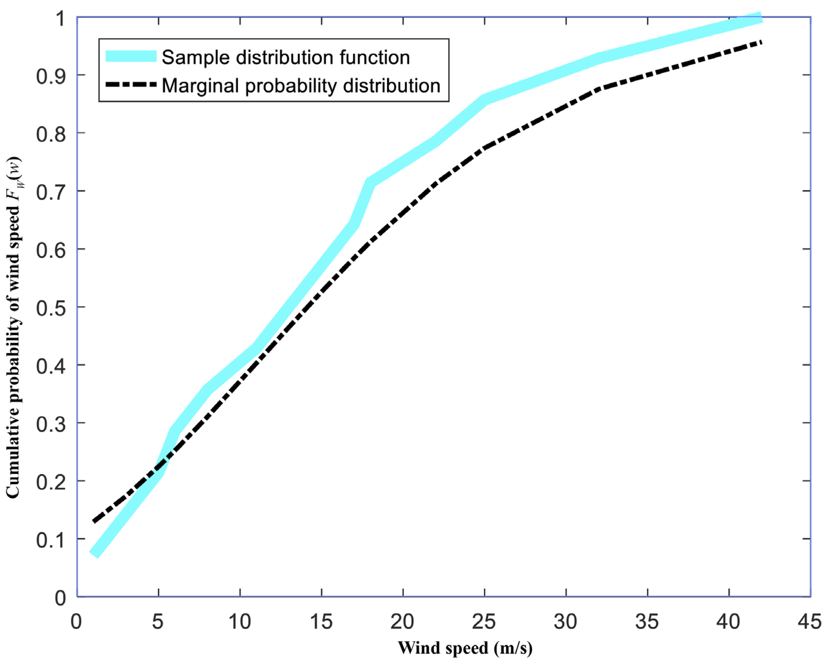
Figure 2 shows the relationship between wind speed and ice-shedding data.
The marginal cumulative distribution of wind speed under ice-shedding conditions was calculated as shown in Figure 3. It is apparent that: (a) when the wind speed was lower than 30 m/s, the probability of transmission line ice-shedding increased rapidly with rising wind speed; (b) when the wind speed exceeded 30 m/s, the probability of transmission line ice-shedding increased slowly with rising wind speed.
(2) Calculation of marginal probability distribution of the “temperature” key factor in ice-shedding
Figure 4 shows the relationship between temperature and ice-shedding.
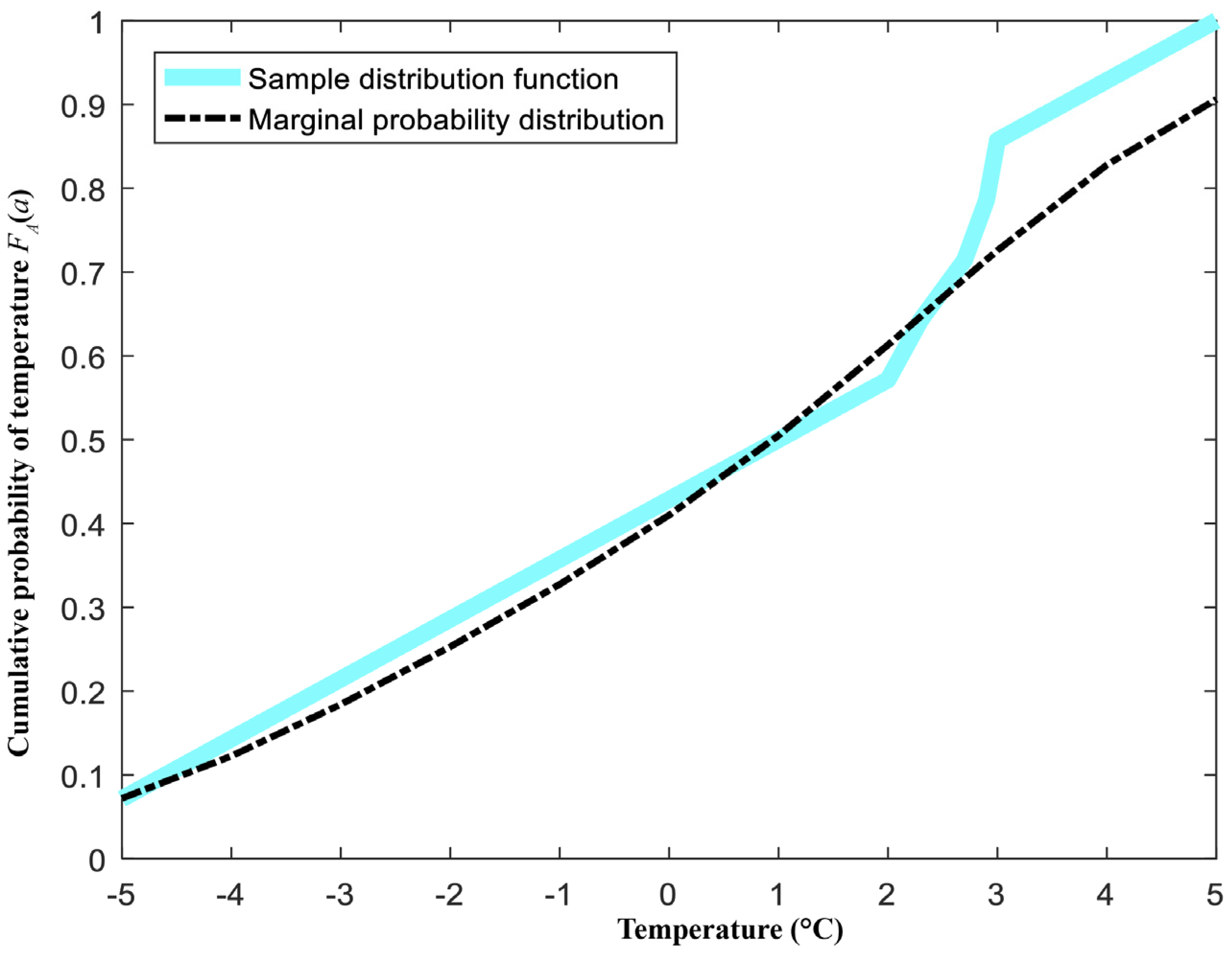
Figure 5 shows the marginal cumulative probability distribution of ice-shedding temperature on a transmission line. It is clear that when the temperature was below −8 °C, the probability of ice-shedding increased slowly with rising temperature; when the temperature was above −8 °C, the probability of ice-shedding increased rapidly with rising temperature.

4.2.2. Calculated Multiple-Factor Joint Probability Distribution of Transmission Line Ice-Shedding

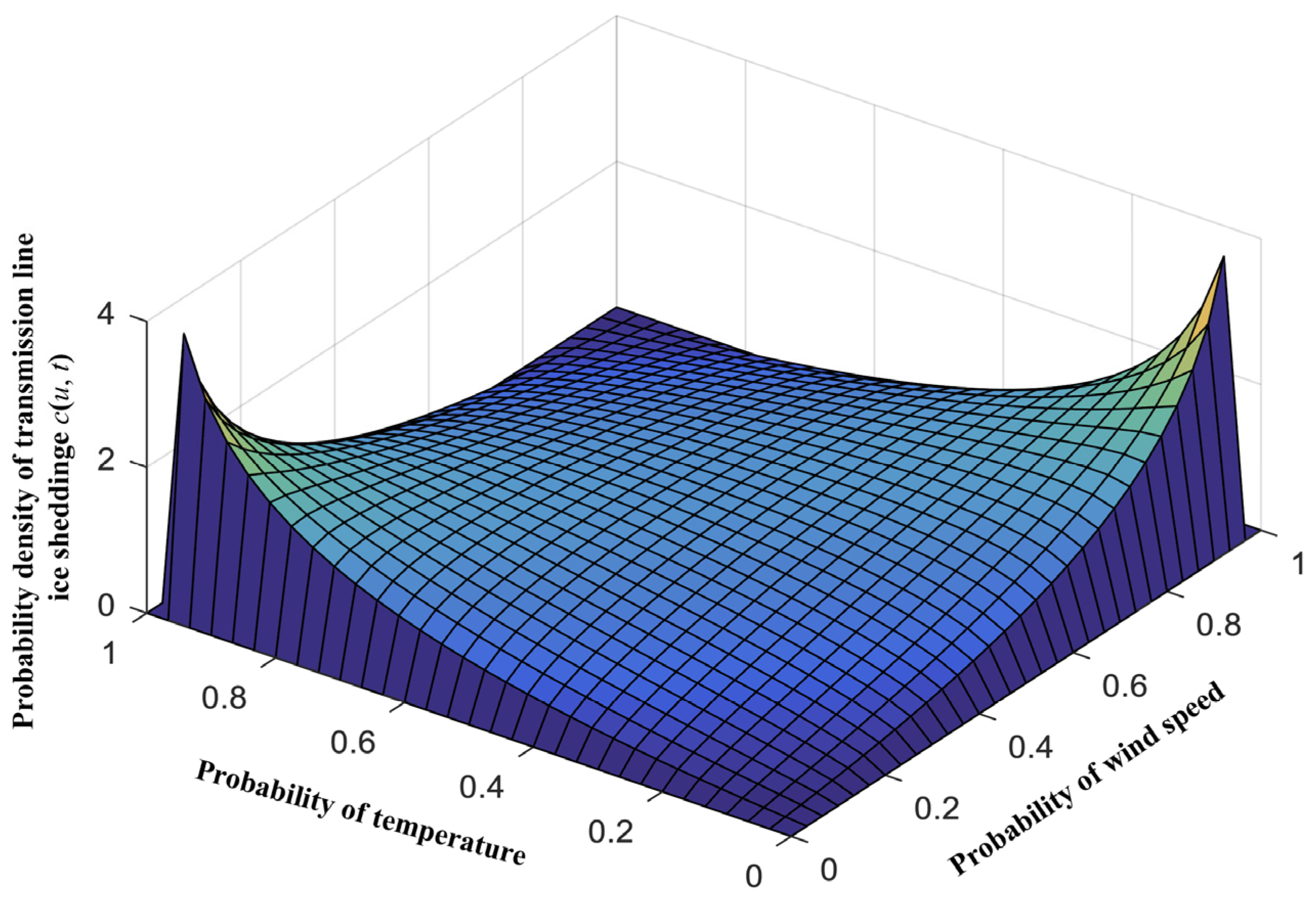
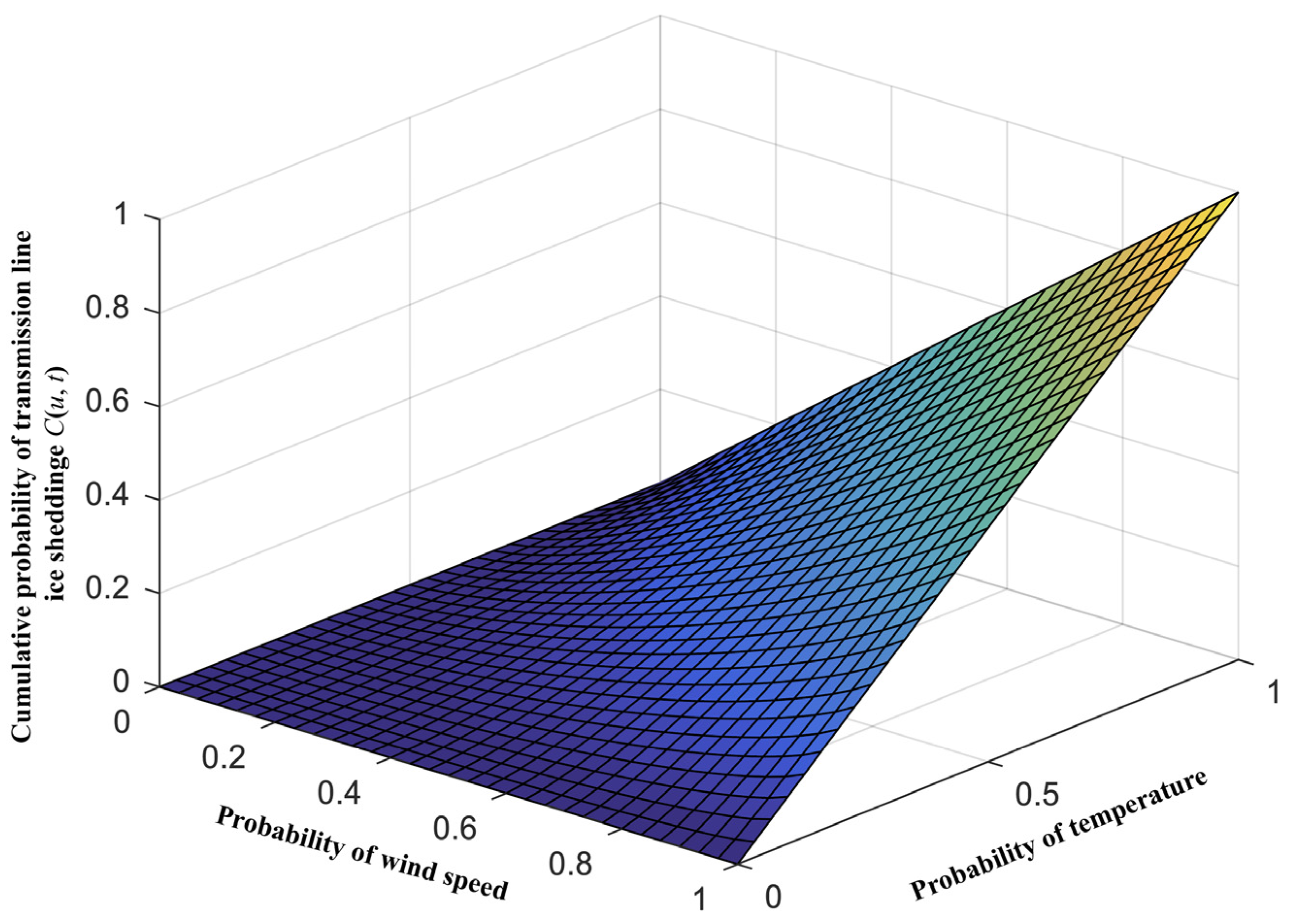
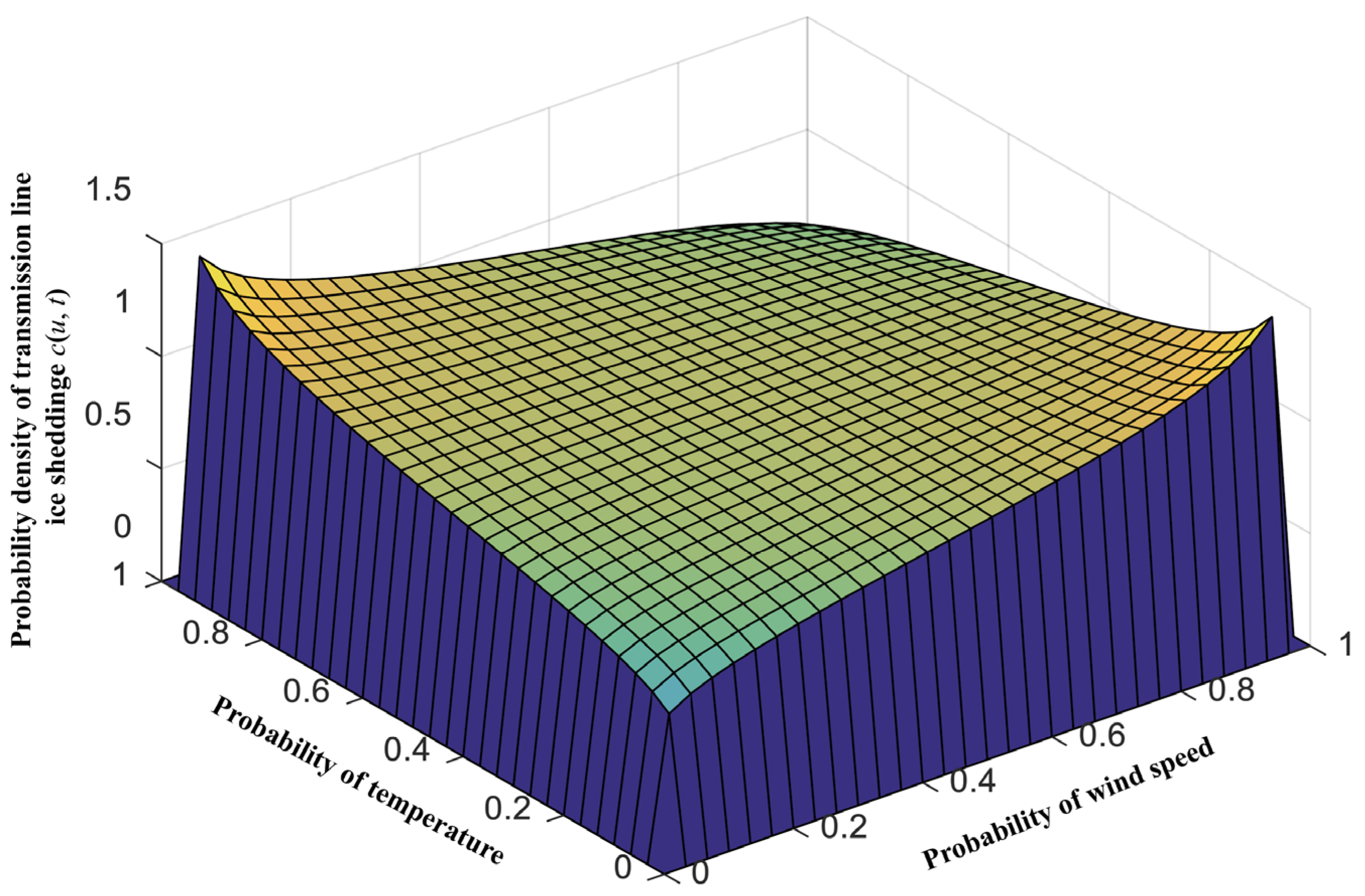
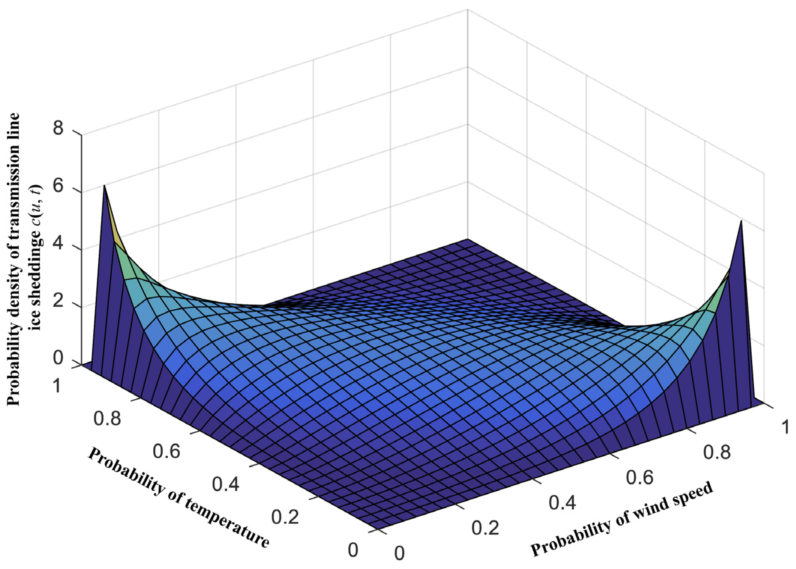
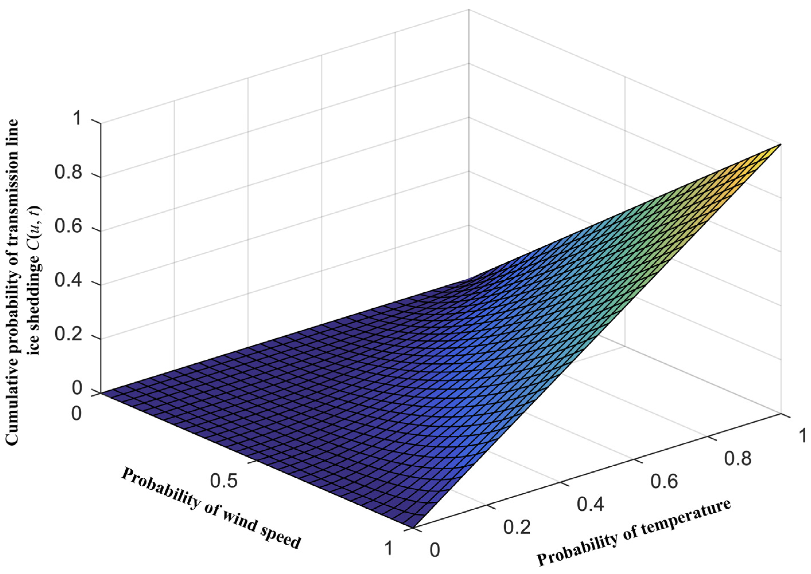
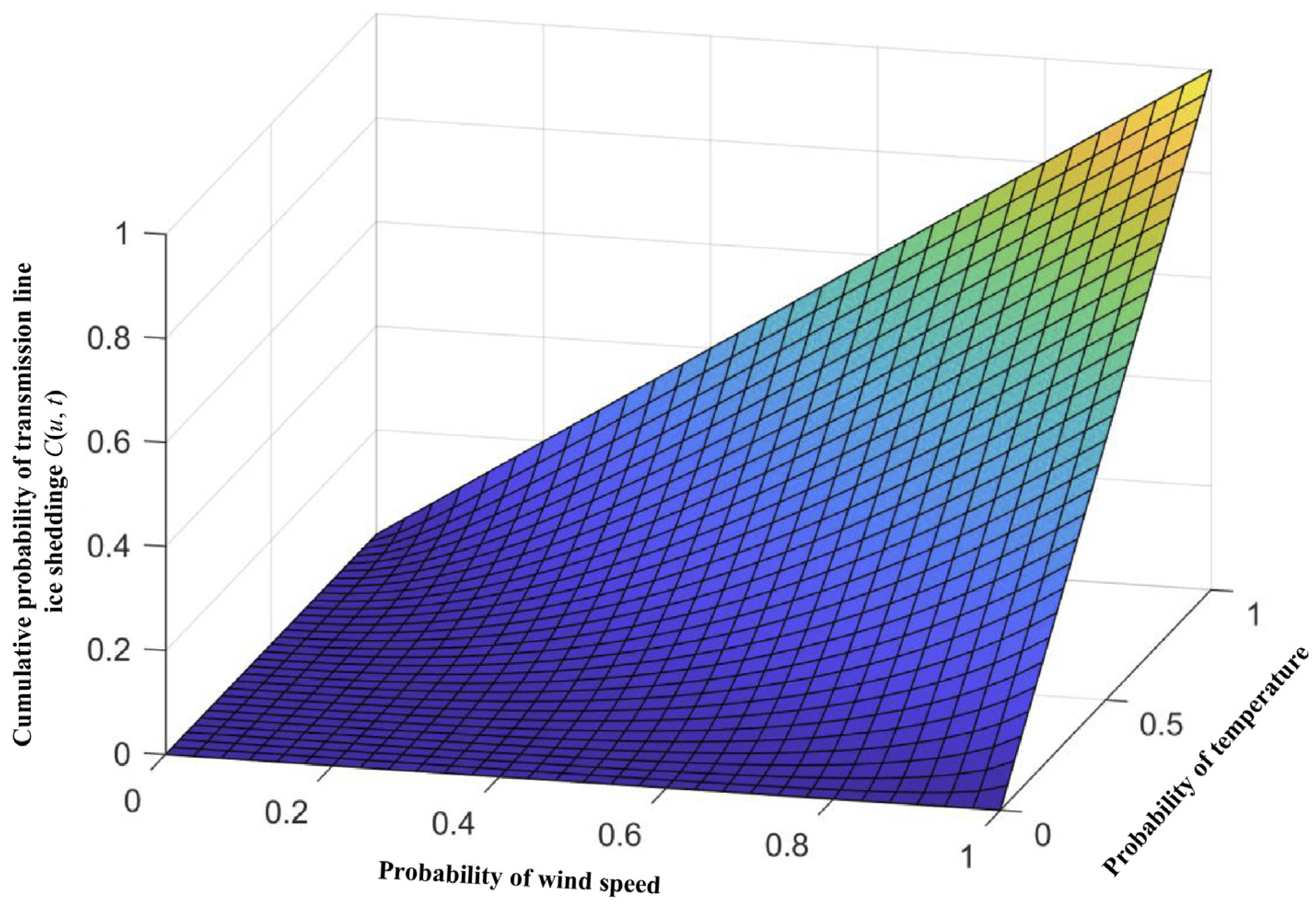
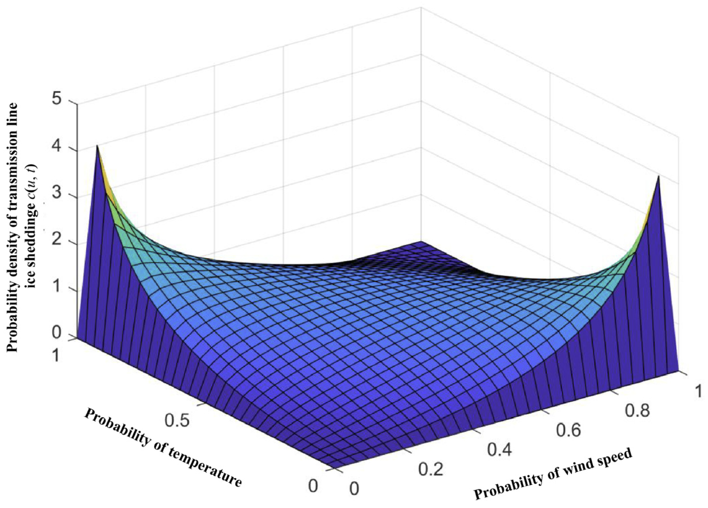
Figure 6 shows the multiple-factor joint probability density of transmission line ice-shedding. Figure 7 shows the multiple-factor joint cumulative probability distribution of transmission line ice-shedding.
In Figure 6 and Figure 7, u represents the value of wind speed in the marginal probability distribution, and t represents the value of temperature in the marginal probability distribution. The c(u, t) in Figure 6 denotes the probability density of transmission line ice-shedding taking according both wind and temperature. If the c(u, t) gets a big value, this means that a large number of values near this big value c(u, t) can be obtained by taking different values of wind speed and temperature, and vice versa. By integrating c(u, t), the cumulative probability distribution function C(u, t) can be obtained. The C(u, t) in Figure 7 represents the multiple-factor joint cumulative probability of transmission line ice-shedding due to both melting and mechanical breakage (this value can be treated as the probability of transmission line ice-shedding due to both melting and mechanical breakage).
The expression of the multiple-factor joint cumulative probability density of transmission line ice-shedding due to both melting and mechanical breakage is shown in the following formula.
C ( u , t ) = 1 4 . 0246 ln 1 + e 4.0246 u 1 e 4.0246 t 1 e 4.0246 1
Figure 6 and Figure 7 reveal that when the temperature was low (below −8 °C), the probability of transmission line ice-shedding increased slowly with rising wind speed. When the temperature was elevated to a certain extent (above −8 °C), the probability of transmission line ice-shedding increased rapidly with rising wind speed.

4.2.3. Calculation of Transmission Line Ice-Shedding Failure Probability

According to the multiple-factor joint probability distribution of transmission line ice-shedding calculated in Section 4.2.2, the actual icing process of the Yunnan power grid from 2018 to 2019 was taken as an example. Table 1 shows the calculated results. The results can be obtained as: The marginal cumulative probability of wind speed is first obtained by querying the wind speed value in Figure 3. Then, the marginal cumulative probability of temperature is obtained by querying the temperature value in Figure 5. Next, according to the obtained marginal cumulative probability of wind speed and temperature, corresponding to the x-axis (Probability of wind speed) and y-axis (Probability of temperature) in Figure 7, the value of the z-axis can be queried, which is the multiple-factor joint cumulative probability of transmission line ice-shedding.
Table 1 shows that ice-shedding will happen when the probability of ice-shedding failure exceeds 32%. These calculated results for ice-shedding probability are in close agreement with the actual situation.
Take the line 1 in Table 1 for example, the calculation process of C(u, t) is explained as follows:
  • From the marginal probability distribution of wind (Figure 3), the value of wind speed 17.5 m/s in the marginal probability distribution can be obtained as u = 0.4916. That is to say, when the x-axis value in Figure 3 is 17.5 m/s, the y-axis value is 0.4916.
  • From the marginal probability distribution of temperature (Figure 5), the value of temperature speed 4 °C in the marginal probability distribution can be obtained as t = 0.9018. That is to say, when the x-axis value in Figure 5 is 4 °C, the y-axis value is 0.9018.
  • By substituting the values of u and t into Formula (5), the joint probability value at this wind speed and temperature can be calculated to be 40.77%.

4.3. Calculated Ice-Shedding Results Due to Melting Alone

4.3.1. Calculated Results for the Marginal Probability Distributions of the Influence Factors in Transmission Line Ice-Shedding

(1) Calculation of marginal probability distribution of the “wind speed” key factor in ice-shedding
Figure 8 shows the calculated marginal cumulative distribution of wind speed under ice-shedding conditions.
Figure 8 shows that: (a) when the wind speed was lower than 20 m/s, the probability of transmission line ice-shedding due to melting increased rapidly with rising wind speed; (b) when the wind speed exceeded 20 m/s, the probability of transmission line ice-shedding due to melting increased slowly with rising wind speed.
(2) Calculated marginal probability distribution of the “temperature” key factor in ice-shedding
Figure 9 shows the marginal cumulative probability distribution of the ice-shedding temperature of transmission lines. Evidently, the probability of ice-shedding due to melting increased slowly with rising temperature.

4.3.2. Calculated Multiple-Factor Joint Probability Distributions of Transmission Line Ice-Shedding

The expression of the multiple-factor joint cumulative probability density of transmission line ice-shedding due to melting is shown in the following formula.
C ( u , t ) = 1 1 . 3117 ln 1 + e 1.3117 u 1 e 1.3117 t 1 e 1.3117 1
where, C(u, t) represents the multiple-factor joint cumulative probability of transmission line ice-shedding due to melting (this value can be treated as the probability of transmission line ice-shedding due to melting alone), u represents the value of wind speed in the marginal probability distribution, and t represents the value of temperature in the marginal probability distribution.
Figure 10 shows the multiple-factor joint probability density of transmission line ice-shedding. Figure 11 shows multiple-factor joint cumulative probability distribution of transmission line ice-shedding. Figure 10 and Figure 11 revealed that the probability of transmission line ice-shedding due to melting increased slowly with rising wind speed and temperature.

4.3.3. Calculation of Transmission Line Ice-Shedding Failure Probability

According to the multiple-factor joint probability distributions of transmission line ice-shedding calculated in Section 4.3.2, the actual icing process of the Yunnan power grid from 2018 to 2019 was taken as an example. Table 2 shows the calculated results.
Table 2 shows the following: (1) lines 1 and 2 may experience ice-shedding due to ice melting; (2) lines 3 to 10 will not experience ice-shedding due to ice melting; (3) the ice-shedding probabilities of lines 1 and 2 are greater than the results in Table 1; (4) lines 3 to 5 may experience ice-shedding due to other reasons.

4.4. Ice-Shedding Calculation Results Due to Mechanical Breakage Alone

4.4.1. Calculated Marginal Probability Distributions of the Influence Factors of Transmission Line Ice-Shedding

(1) Calculation of marginal probability distribution of the “wind speed” key factor in ice-shedding
Figure 12 shows the calculated marginal cumulative distribution of wind speed under ice-shedding conditions.
Figure 12 shows that: (a) when the wind speed was lower than 30 m/s, the probability of transmission line ice-shedding due to melting increased rapidly with rising wind speed; (b) when the wind speed exceeded 30 m/s, the probability of transmission line ice-shedding due to melting increased slowly with rising wind speed.
(2) Calculation of marginal probability distribution of the “temperature” key factor in ice-shedding
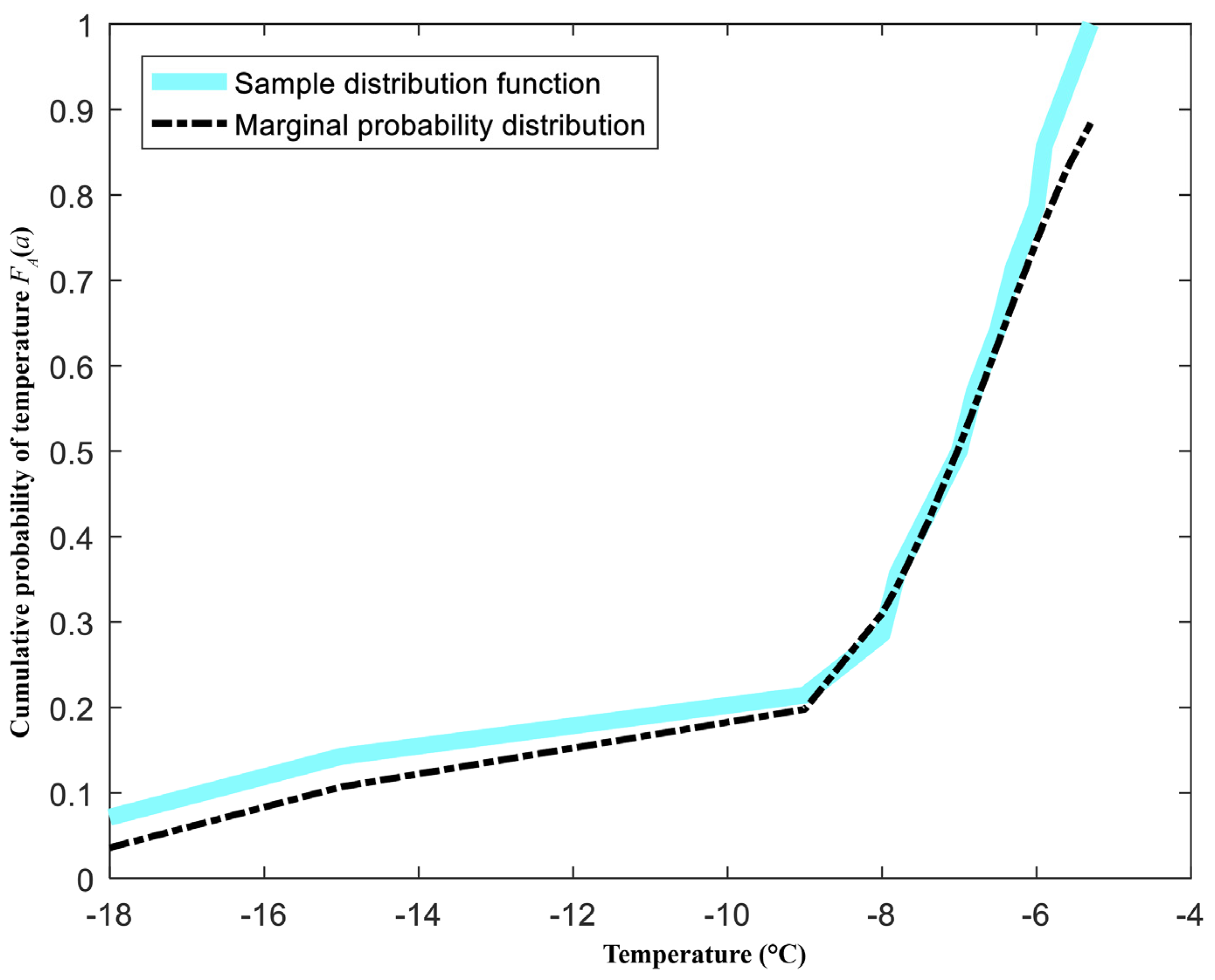
Figure 13 shows the marginal cumulative probability distribution of the ice-shedding temperature of a transmission line. The figure shows that: (a) when the temperature was below −9 °C, the probability of ice-shedding due to melting increased slowly with rising temperature; and (b) when the temperature exceeded −9 °C, the probability of ice-shedding due to melting increased more rapidly.

4.4.2. Calculated Multiple-Factor Joint Probability Distribution of Transmission Line Ice-Shedding

The expression of the multiple-factor joint cumulative probability density of transmission line ice-shedding due to mechanical breakage is shown in the following formula.
C ( u , t ) = 1 6 . 6384 ln 1 + e 6.6384 u 1 e 6.6384 t 1 e 6.6384 1
where, C(u, t) represents the multiple-factor joint cumulative probability of transmission line ice-shedding due to mechanical breakage (this value can be treated as the probability of transmission line ice-shedding due to mechanical breakage alone), u represents the value of wind speed in the marginal probability distribution, and t represents the value of temperature in the marginal probability distribution.
Figure 14 shows the multiple-factor joint probability density of transmission line ice-shedding. Figure 15 shows the multiple-factor joint cumulative probability distribution of transmission line ice-shedding. Figure 14 and Figure 15 clearly show that the probability of transmission line ice-shedding due to mechanical breakage increased slowly with rising wind speed and temperature.

4.4.3. Calculation of Transmission Line Ice-Shedding Failure Probability

According to the multiple-factor joint probability distributions of transmission line ice-shedding calculated in Section 4.4.2, the actual icing process in the Yunnan power grid from 2018 to 2019 was taken as an example. Table 3 shows the calculated results.
The results in Table 3 show the following: (1) lines 3–5 may experience ice-shedding due to mechanical breakage; (2) lines 1–2, 6–10 will not experience ice-shedding due to mechanical breakage; (3) the ice-shedding probabilities of lines 2–5 are greater than the results in Table 1; (4) lines 1–2 may experience ice-shedding due to other reasons.

4.5. Ice-Shedding Calculation Results under Different Type of Ice

4.5.1. Calculated Multiple-Factor Joint Probability Distributions of Transmission Line Glaze Ice-Shedding

The expression of the multiple-factor joint cumulative probability density of transmission line glaze ice-shedding is shown in the following formula.
C ( u , t ) = 1 3 . 3042 ln 1 + e 3.3042 u 1 e 3.3042 t 1 e 3.3042 1
where, C(u, t) represents the multiple-factor joint cumulative probability of transmission line glaze ice-shedding (this value can be treated as the probability of transmission line due to glaze ice-shedding), u represents the value of wind speed in the marginal probability distribution, and t represents the value of temperature in the marginal probability distribution.
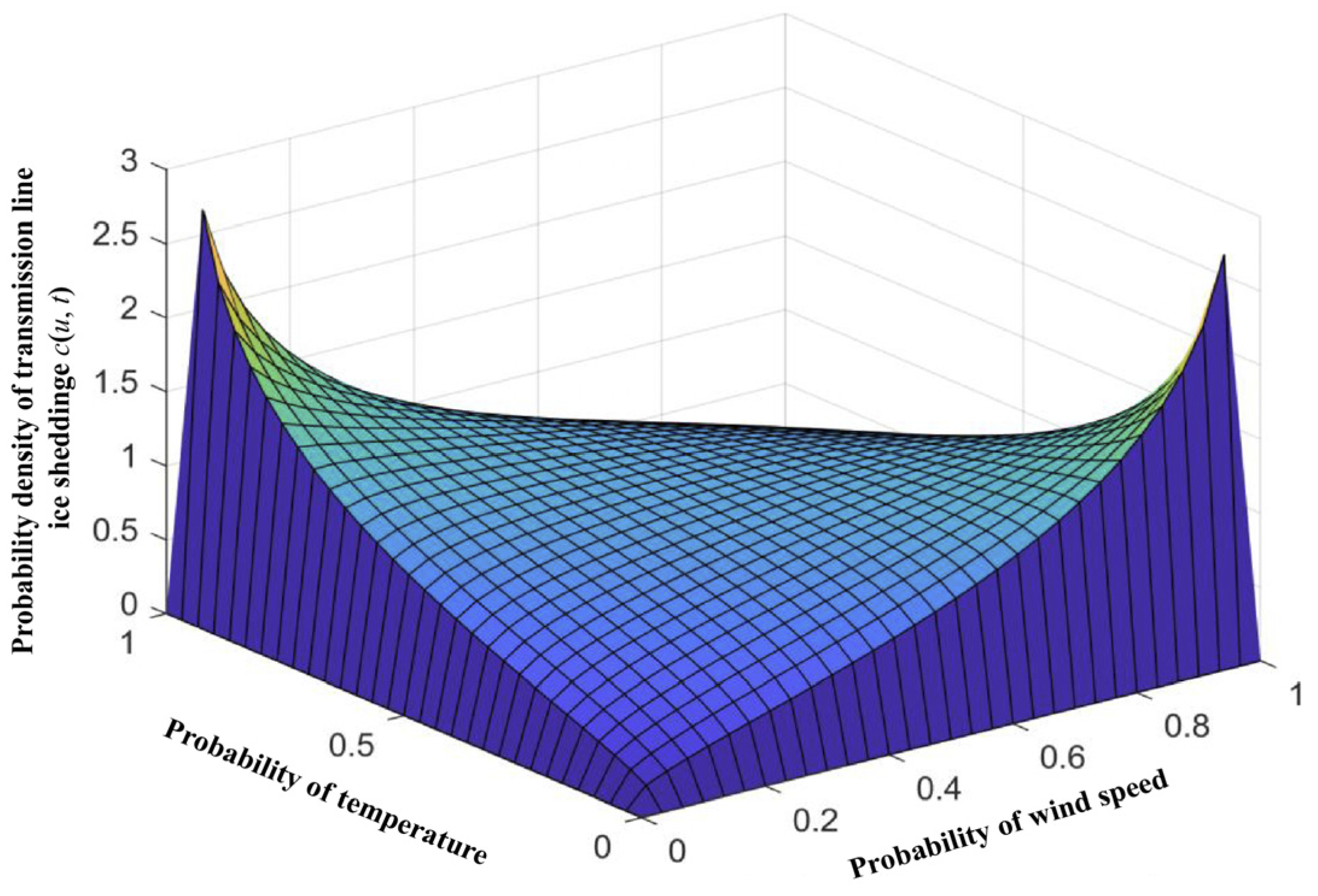
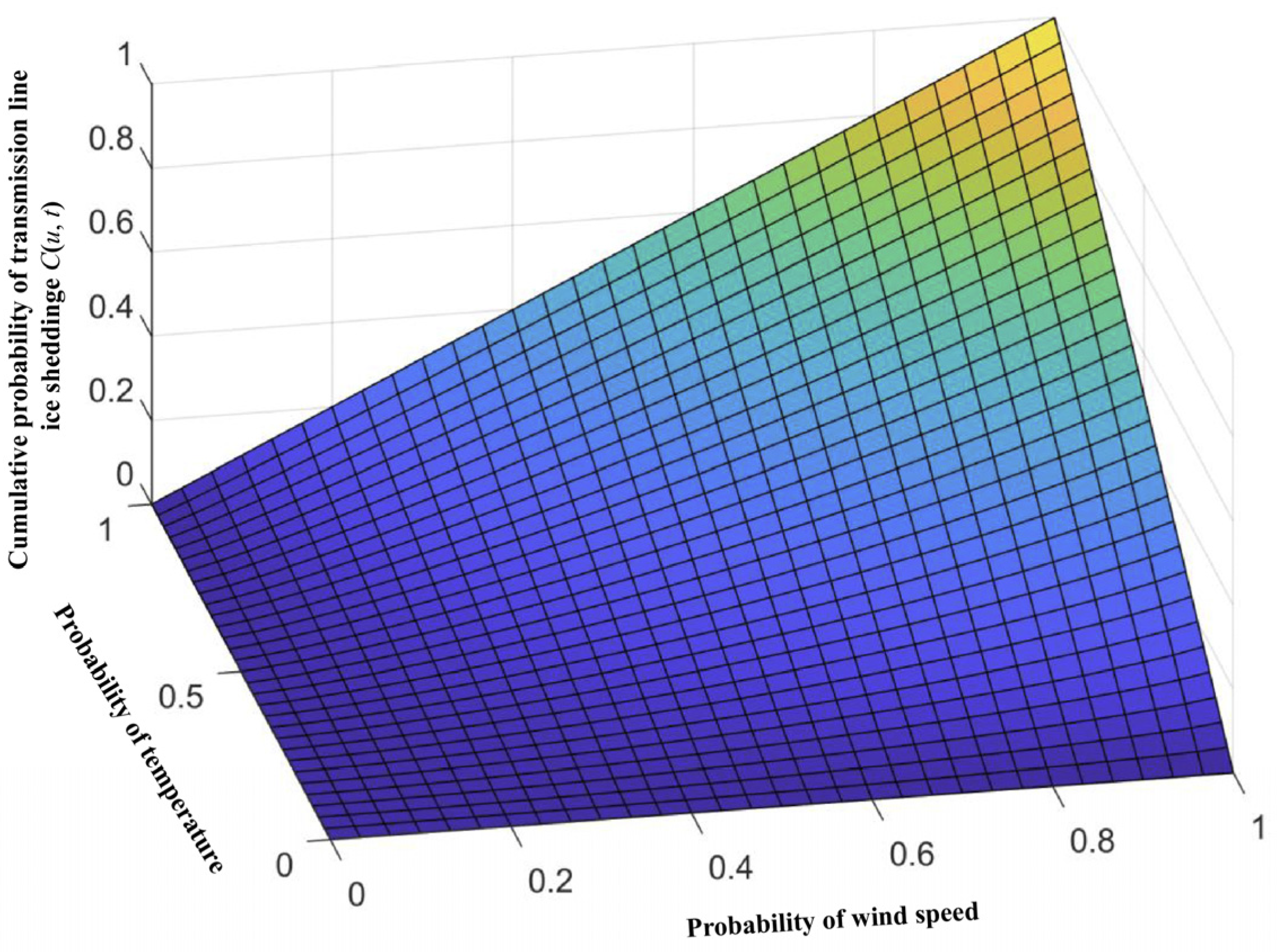
Figure 16 shows the multiple-factor joint probability density of transmission line glaze ice-shedding. Figure 17 shows the multiple-factor joint cumulative probability distribution of transmission line glaze ice-shedding. Figure 16 and Figure 17 clearly show that the increase in temperature has a more significant impact on the probability of transmission line ice-shedding than the increase in wind speed. The main reason may be that the glaze is relatively dense, and lower wind speeds make it difficult to ice-shedding. The increase in temperature leads to the ice melting of conductor, which is more likely to cause ice-shedding.

4.5.2. Calculated Multiple-Factor Joint Probability Distributions of Transmission Line Hard Rime Ice-Shedding

The expression of the multiple-factor joint cumulative probability density of transmission line hard rime ice-shedding is shown in the following formula.
C ( u , t ) = 1 6 . 9068 ln 1 + e 6.9068 u 1 e 6.9068 t 1 e 6.9068 1
where, C(u, t) represents the multiple-factor joint cumulative probability of transmission line hard rime ice-shedding (this value can be treated as the probability of transmission line due to hard rime ice-shedding), u represents the value of wind speed in the marginal probability distribution, and t represents the value of temperature in the marginal probability distribution.
Figure 18 shows the multiple-factor joint probability density of transmission line hard rime ice-shedding. Figure 19 shows the multiple-factor joint cumulative probability distribution of transmission line hard rime ice-shedding. Figure 18 and Figure 19 show that the probability of transmission line hard rime ice-shedding increased slowly with rising wind speed and temperature. Compared to glaze ice, hard rime is less dense, and the increasing of wind speed is more likely to cause ice-shedding.

4.5.3. Calculated Multiple-Factor Joint Probability Distributions of Transmission Line Soft Rime Ice-Shedding

The expression of the multiple-factor joint cumulative probability density of transmission line soft rime ice-shedding is shown in the following formula.
C ( u , t ) = 1 4 . 2731 ln 1 + e 4.2731 u 1 e 4.2731 t 1 e 4.2731 1
where, C(u, t) represents the multiple-factor joint cumulative probability of transmission line soft rime ice-shedding (this value can be treated as the probability of transmission line due to soft rime ice-shedding), u represents the value of wind speed in the marginal probability distribution, and t represents the value of temperature in the marginal probability distribution.
Figure 20 shows the multiple-factor joint probability density of transmission line soft rime ice-shedding. Figure 21 shows the multiple-factor joint cumulative probability distribution of transmission line soft rime ice-shedding. Figure 20 and Figure 21 show that the probability of transmission line soft rime ice-shedding increased with rising wind speed and temperature. Due to the lower density of soft rime, compared to glaze and hard rime, it is more likely to cause ice-shedding with increasing temperature and wind speed.

4.5.4. Calculation of Transmission Line Ice-Shedding Failure Probability

According to the multiple-factor joint probability distributions of transmission line ice-shedding calculated in Section 4.5.1, Section 4.5.2 and Section 4.5.3, the actual icing process in the Yunnan power grid from 2018 to 2019 was taken as an example. Table 4 shows the calculated results under different type of ice.

5. Comparison and Discussion

5.1. Comparison of Different Type of Ice-Shedding

According to the results in Table 1, Table 2 and Table 3, it can be noted that when considering the two types of ice-shedding, ice melting and mechanical ice-shedding, separately for calculation, some lines have lower calculated failure probabilities because the actual ice-shedding type does not match the calculated ice-shedding type (for example, the line with ID 3 may not belong to ice melting, so the calculated ice melting failure probability is much smaller and does not match the actual situation).
Therefore, this paper proposed a comprehensive ice-shedding failure probability calculation method. For each line in Table 1, Table 2 and Table 3, the maximum probability was selected as the comprehensive ice-shedding failure probability. The comprehensive ice-shedding calculation results are presented in Table 5.
Through the results in Table 5, not only the transmission line ice-shedding failure probability, but also the type of ice-shedding can be obtained. For example, lines 1–2 may experience ice-shedding due to ice melting, whereas lines 3–5 may experience ice-shedding due to mechanical breakage. The results in Table 5 are in closer agreement with the actual situation. The results can provide a scientific basis for dealing with icing disasters on transmission lines.

5.2. Comparison of Probability Calculation Results for Different Icing Types and Different Ice-Shedding Mechanisms

Since the icing type of transmission lines has an important impact on ice-shedding, the ice-shedding probabilities under three different icing types are calculated in Section 4.5, and the results are shown in Table 4. The results of Table 4 are consistent with those of Table 5. When the icing type is considered, the calculated ice-shedding failure probability is most consistent with the actual situation.
This also indicates that it is reasonable to calculate the probability of ice-shedding faults based on the icing type of the transmission lines. In other words, the probability of ice-shedding faults can be directly calculated by dividing the icing types of transmission lines, without using the methods in Section 4.2, Section 4.3 and Section 4.4 to calculate multiple probabilities of ice-shedding faults.

6. Conclusions

This study analyzed the key influence factors and their probability distributions with respect to transmission line ice-shedding. A copula-based multiple-factor coupling fault probability calculation model for transmission line ice-shedding has been proposed. This method can consider multiple influence factors at the same time and calculate the failure probability directly. Taking the icing disaster of the Yunnan power grid as an example, the accuracy of the proposed method was verified. Moreover, the results shown in Table 1, Table 2 and Table 3 indicate that transmission line ice-shedding failure probabilities should be calculated due to ice melting and mechanical breakage, respectively. In this way, not only the transmission line ice-shedding failure probability, but also the type of ice-shedding can be obtained. The method proposed in this study can provide an important decision-making basis for the prevention and mitigation of transmission line ice-shedding faults and has important theoretical and practical engineering value. In addition, this paper calculates the probability of ice-shedding faults based on the icing type of the conductor, and obtains consistent results with Table 1, Table 2 and Table 3. And the probability of ice-shedding faults can be directly calculated by dividing the icing types of transmission lines, without the need to calculate multiple fault probabilities based on different ice-shedding mechanisms.

Author Contributions

Conceptualization, H.P. and Y.M. (Yi Ma); Data curation, H.P., Y.M. (Yi Ma) and Y.M. (Yutang Ma); Funding acquisition, H.P.; Resources, F.Z.; Validation, Y.M. (Yi Ma); Investigation, P.Q.; Formal analysis, J.G.; Methodology, J.G.; Writing—original draft, J.G.; Writing—review and editing, J.G. All authors have read and agreed to the published version of the manuscript.

Funding

This work was supported in part by the Science and Technology Project of China Southern Power Grid Corporation (Research on Multi-time Scale Ice Monitoring and Prediction Technology Based on Multi-information Fusion, Topic 2 and 4, No. YNKJXM20210174).

Data Availability Statement

The data sources used are described in the article.

Acknowledgments

Special thanks are given to the anonymous reviewers and editors for their constructive comments.

Conflicts of Interest

Authors Hao Pan, Fangrong Zhou, Yi Ma, Yutang Ma were employed by the company Yunnan Power Grid Company Ltd. Author Ping Qiu was employed by the company Yunnan Power Grid Company Ltd. The remaining authors declare that the research was conducted in the absence of any commercial or financial relationships that could be construed as a potential conflict of interest.

References

  1. Lu, J.; Jiang, Z.; Lei, H.; Zhang, H.; Peng, J.; Li, B.; Fang, Z. Analysis of Hunan Power Grid Ice Disaster Accident in 2008. Auto Electr. Power Syst. 2008, 32, 16–19. [Google Scholar]
  2. Savadjiev, K.; Farzaneh, M. Study of icing rate and related meteorological parameter distributions during atmospheric icing events. In Proceedings of the 11th International Offshore and Polar Engineering Conference, Stavanger, Norway, 17–22 June 2001; Volume 1, pp. 665–670. [Google Scholar]
  3. Savadjiev, K.; Farzaneh, M. Modeling of icing and ice shedding on overhead power lines based on statistical analysis of meteorological data. IEEE Trans. Power Deliv. 2004, 19, 715–721. [Google Scholar] [CrossRef]
  4. Wagner, T. Modelling of Wind Borne Ice Accretion on Power Transmission Lines. Ph.D. Thesis, Technische University, Braunschweig, Germany, 2010. [Google Scholar]
  5. Hou, L.; Wang, L.; Zhu, P.; Guan, Z. Dynamic Behavior Computation of Ice Shedding of UHV Overhead Transmission Lines. Proc. Chin. Soc. Electr. Eng. 2008, 28, 1–6. [Google Scholar]
  6. Liang, C. Research on Ice Shedding from 220 kV-Double-Circle Transmission Line in Heavy Icing Area. Master’s Thesis, North China Electric Power University, Baoding, China, 2017. [Google Scholar]
  7. Wu, C. Study on Jump Height after Ice-shedding and Galloping Oscillation Characteristics of Transmission Lines. Ph.D. Thesis, Chongqing University, Chongqing, China, 2017. [Google Scholar]
  8. Zhao, Y.; Li, L.; Deng, W. Transmission lines ice-shedding numerical simulation jump-height after ice shedding horizontal amplitude. Water Res. Power 2013, 31, 211–215. [Google Scholar]
  9. Xu, G. Numerical Simulation Study of Iced Conductor on Dynamic Response of Ice-Shedding on Transmission Lines. Master’s Thesis, Xi’an Technology University, Xi’an, China, 2016. [Google Scholar]
  10. Yan, B.; Chen, K.; Xiao, H.; Li, L.; Yi, W. Horizontal amplitude of iced conductor after ice-shedding under wind load. Chin. J. Appl. Mech. 2013, 30, 913–919. [Google Scholar]
  11. Deng, W. Numerical Simulation Research of Unbalanced Tension of Ice-Shedding on Transmission Lines. Master’s Thesis, Huazhong University of Science and Technology, Wuhan, China, 2013. [Google Scholar]
  12. Long, H. Modeling on Transmission Tower-line System and Simulation Research on the Jumping of Transmission Line after Ice-shedding. Master’s Thesis, Hunan University of Science and Technology, Xiangtan, China, 2015. [Google Scholar]
  13. Li, H.; Wu, Y.; Fu, X.; Du, W. Dynamic Response of Transmission Lines Following Ice Shedding via a Three-Dimensional Motion Capture System. Int. J. Struct. Stab. Dyn. 2022, 22, 2250175. [Google Scholar] [CrossRef]
  14. Ye, Z.; Wu, C.; Liu, X.; Huang, F. Numerical Simulation of the Dynamic Responses of Electric Power Fitting of Transmission Lines after Ice Shedding. Shock Vib. 2022, 2022, 3675271. [Google Scholar] [CrossRef]
  15. Li, J.; Wang, B.; Sun, J.; Wang, S.; Zhang, X.; Fu, X. Collapse Analysis of a Transmission Tower-Line System Induced by Ice Shedding. Front. Phys. 2021, 9, 712161. [Google Scholar] [CrossRef]
  16. Huang, G.; Yan, B.; Guo, Y.; Zhang, B.; Wu, G. Experimental study on dynamic response characteristics of isolated-span transmission lines after ice-shedding. High Volt. 2023, 8, 196–208. [Google Scholar] [CrossRef]
  17. Lou, W.; Zhang, Y.; Xu, H.; Huang, M.; Zhang, B.; Bian, R. Field experiments on ice-accretion and ice-shedding processes of power transmission lines based on a conductor segment model. China Civil Eng. J. 2022, 55, 27–35. [Google Scholar]
  18. Li, H.; Wu, Y. Experimental study on dynamic responses of transmission lines caused by ice shedding. China Civil Eng. J. 2019, 52, 35–46, 100. [Google Scholar]
  19. Huang, G.; Yan, B.; Wen, N.; Wu, C.; Li, Q. Study on jump height of transmission lines after ice-shedding by reduced-scale modeling test. Cold Reg. Sci. Technol. 2019, 165, 102781. [Google Scholar] [CrossRef]
  20. Wang, L.; Cao, L.; Mei, H.; Huang, T.; Gao, Y. Simulation Research on Suppressing Measures Against Severe Ice-shedding Jump of UHVAC Double-circuit Transmission Lines on the Same Tower. High Volt. Eng. 2018, 44, 1475–1482. [Google Scholar]
  21. Xie, Y.; Huang, L.; Wang, D.; Ding, H.; Yin, X. Modeling and analysis of progressive ice shedding along a transmission line during thermal de-icing. Math. Probl. Eng. 2019, 2019, 4851235. [Google Scholar] [CrossRef]
  22. Yang, F.; Yang, J.; Li, Z.; Han, J.; Fu, D. Ice shedding and vibration suppression of a transmission line system. J. Vib. Shock 2010, 29, 20–25. [Google Scholar]
  23. Li, L.; Zhang, X.; Yin, P. Control for Jumping Response Induced by Ice-Shedding of Transmission Lines. J. Vib. Shock 2008, 27, 61–64, 80, 192. [Google Scholar]
  24. Yin, P.; Li, L.; Zhang, X. Investigation on Control of Jumping Induced by Transmission Line Ice-Shedding. Adv. Power Syst. Hydroelectr. Eng. 2008, 24, 3–7. [Google Scholar]
  25. Huang, W. Study on Tower-Line System Ice-Shedding Jump and Vibration Reduction. Master’s Thesis, Hunan University of Science and Technology, Xiangtan, China, 2016. [Google Scholar]
  26. Song, C. Dynamic Properties and Vibration Control on Wire-Breaking and Ice-Shedding of Transmission Tower-Line System. Master’s Thesis, Wuhan University of Technology, Wuhan, China, 2013. [Google Scholar]
  27. Wu, J.; Xu, C. Major Chinese cities’ solar radiant intensities in winter. J. Harbin Inst. Technol. 2003, 35, 1236–1239. [Google Scholar]
  28. Zhang, S. FEM Simulations on Temperature Rising and Mechanical Responses of Transmission Lines under Increasing Current Capacity. Master’s Thesis, Huazhong University of Science & Technology, Wuhan, China, 2014. [Google Scholar]
  29. Yan, M.; Zhou, Z.; Wen, J.; Guo, C.; Lu, J. Assessment Method for Power Grid Icing Risk Based on Short-term Icing Forecasting. Auto. Electr. Power Syst. 2016, 40, 168–175. [Google Scholar]
  30. Lu, J.; Guo, J.; Hu, J.; Yang, L.; Feng, T. Analysis of ice disasters on ultra-high-voltage direct-current transmission lines. Nat. Hazards 2017, 86, 203–217. [Google Scholar] [CrossRef]
  31. Guo, J.; Liu, Y.; Zou, Q.; Ye, L.; Zhu, S.; Zhang, H. Study on optimization and combination strategy of multiple daily runoff prediction models coupled with physical mechanism and LSTM. J. Hydrol. 2023, 624, 129969. [Google Scholar] [CrossRef]
  32. Nelsen, R.B. An Introduction to Copulas; Springer: New York, NY, USA, 2006. [Google Scholar]
  33. Wang, D.; Yan, B.; Huang, G.; Huang, X.; Li, M. Simplified formula for jump height of transmission lines after ice-shedding. J. Chongqing Univ. (Nat. Sci. Ed.) 2020, 43, 64–71. [Google Scholar]
  34. GB/T 35706-2017; Technical Rule for Ice Mapping of Power Grid. Standards Press of China: Beijing, China, 2017.
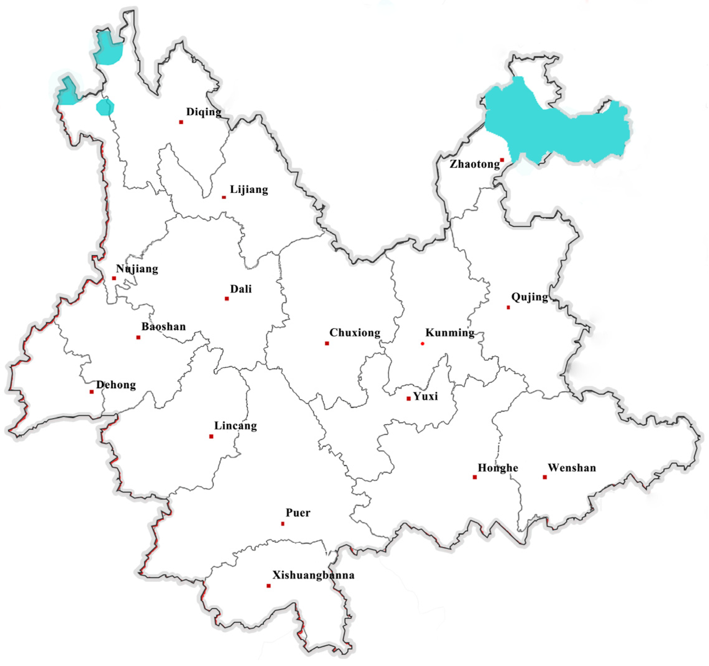
Figure 1. Icing thicknesses predicted by the system.
Energies 17 01208 g001
Figure 2. Data relationship between wind speed and ice-shedding.
Energies 17 01208 g002
Figure 3. Marginal cumulative distribution of wind speed under ice-shedding conditions.
Energies 17 01208 g003
Figure 4. Relationship between temperature and ice-shedding.
Energies 17 01208 g004
Figure 5. Marginal cumulative probability distribution of temperature under ice-shedding conditions.
Energies 17 01208 g005
Figure 6. Multiple-factor joint probability density of transmission line ice-shedding.
Energies 17 01208 g006
Figure 7. Multiple-factor joint cumulative probability distribution of transmission line ice-shedding.
Energies 17 01208 g007
Figure 8. Marginal cumulative distribution of wind speed under ice-shedding conditions due to melting alone.
Energies 17 01208 g008
Figure 9. Marginal cumulative distribution of temperature under ice-shedding conditions due to melting alone.
Energies 17 01208 g009
Figure 10. Multiple-factor joint probability density of transmission line ice-shedding due to melting alone.
Energies 17 01208 g010
Figure 11. Multiple-factor joint cumulative probability distribution of transmission line ice-shedding due to melting alone.
Energies 17 01208 g011
Figure 12. Marginal cumulative distribution of wind speed under ice-shedding conditions due to mechanical breakage alone.
Energies 17 01208 g012
Figure 13. Marginal cumulative distribution of temperature under ice-shedding conditions due to mechanical breakage alone.
Energies 17 01208 g013
Figure 14. Multiple-factor joint probability density of transmission line ice-shedding due to mechanical breakage alone.
Energies 17 01208 g014
Figure 15. Multiple-factor joint cumulative probability distribution of transmission line ice-shedding due to mechanical breakage alone.
Energies 17 01208 g015
Figure 16. Multiple-factor joint probability density of transmission line glaze ice-shedding.
Energies 17 01208 g016
Figure 17. Multiple-factor joint cumulative probability distribution of transmission line glaze ice-shedding.
Energies 17 01208 g017
Figure 18. Multiple-factor joint probability density of transmission line hard rime ice-shedding.
Energies 17 01208 g018
Figure 19. Multiple-factor joint cumulative probability distribution of transmission line hard rime ice-shedding.
Energies 17 01208 g019
Figure 20. Multiple-factor joint probability density of transmission line soft rime ice-shedding.
Energies 17 01208 g020
Figure 21. Multiple-factor joint cumulative probability distribution of transmission line soft rime ice-shedding.
Energies 17 01208 g021
Table 1. Results of transmission line ice-shedding failure probability due to both melting and mechanical breaking.
IDTower NumberVoltage LevelTemperature (°C)Wind Speed (m/s)Ice Thickness (mm)>Critical Icing Thickness?Wind Speed in the Marginal Probability Distribution uTemperature in the Marginal Probability Distribution tCopula Function Parameter θProbability of Ice-Shedding FailureObserved Ice-Shedding or Not
146#220 kV417.512Yes0.49160.9018−4.024640.77%Yes
22#220 kV318.816Yes0.52570.8569−4.024640.21%Yes
3128#220 kV−225.215Yes0.67030.6165−4.024632.91%Yes
423#220220.513Yes0.56820.8075−4.024639.93%Yes
51508#±800−1.526.520Yes0.69430.6402−4.024636.79%Yes
675#220 kV−512.512Yes0.35330.4374−4.02466.05%No
7267#500 kV−16.55No0.19700.6633−4.02466.43%No
8211#500 kV210.515Yes0.29840.8075−4.024617.81%No
91760#±500 kV−211.26No0.31740.6165−4.024610.34%No
1024#220 kV−38.513Yes0.24580.5653−4.02465.91%No
Table 2. Results of transmission line ice-shedding failure probability due to melting.
IDTower NumberVoltage LevelTemperature (°C)Wind Speed (m/s)Ice Thickness (mm)> Critical Icing Thickness?Wind Speed in the Marginal Probability Distribution uTemperature in the Marginal Probability Distribution tCopula Function Parameter θProbability of Ice-Shedding FailureObserved Ice-Shedding or Not
146#220 kV417.512Yes0.59850.8279−1.311747.42%Yes
22#220 kV318.816Yes0.63380.7258−1.311743.12%Yes
3128#220 kV−225.215Yes0.77760.2528−1.311717.44%Yes
423#220220.513Yes0.67720.6130−1.311738.24%Yes
51508#±800−1.526.520Yes0.80040.2893−1.311720.93%Yes
675#220 kV−512.512Yes0.44960.0719−1.31172.20%No
7267#500 kV−16.55No0.26650.3273−1.31176.06%No
8211#500 kV210.515Yes0.38730.6130−1.311720.08%No
91760#±500 kV−211.26No0.40910.2528−1.31177.47%No
1024#220 kV−38.513Yes0.32570.1840−1.31173.98%No
Table 3. Results of transmission line ice-shedding failure probability due to mechanical breaking.
IDTower NumberVoltage LevelTemperature (°C)Wind Speed (m/s)Ice Thickness (mm)> Critical Icing Thickness?Wind speed in the Marginal Probability Distribution uTemperature in the Marginal Probability Distribution tCopula Function Parameter θProbability of Ice-Shedding FailureObserved Ice-Shedding or Not
146#220 kV417.512Yes0.38081.0000−6.638438.08%Yes
22#220 kV318.816Yes0.41061.0000−6.638441.06%Yes
3128#220 kV−225.215Yes0.54961.0000−6.638454.96%Yes
423#220220.513Yes0.44911.0000−6.638444.91%Yes
51508#±800−1.526.520Yes0.57551.0000−6.638457.55%Yes
675#220 kV−512.512Yes0.26760.9253−6.638420.84%No
7267#500 kV−16.55No0.15021.0000−6.638415.02%No
8211#500 kV210.515Yes0.22531.0000−6.638422.53%No
91760#±500 kV−211.26No0.23981.0000−6.638423.98%No
1024#220 kV−38.513Yes0.18590.9995−6.638418.55%No
Table 4. Results of transmission line ice-shedding failure probability under different type of ice.
IDTower NumberVoltage LevelTemperature (°C)Wind Speed (m/s)Ice Thickness (mm)>Critical Icing Thickness?Ice TypeWind Speed in the Marginal Probability Distribution uTemperature in the Marginal Probability Distribution tCopula Function Parameter θProbability of Ice-Shedding FailureObserved Ice-Shedding or Not
146#220 kV417.512Yesglaze0.61690.9412−3.304256.43%Yes
22#220 kV318.816Yesglaze0.67850.8824−3.304257.11%Yes
3128#220 kV−225.215Yeshard rime0.70320.8530−6.906855.79%Yes
423#220220.513Yessoft rime0.48810.9998−4.273148.79%Yes
51508#±800−1.526.520Yessoft rime0.64410.9411−4.273158.86%Yes
675#220 kV−512.512Yeshard rime0.30880.7448−6.906811.87%No
7267#500 kV−16.55Nosoft rime0.09960.9603−4.27318.64%No
8211#500 kV210.515Yesglaze0.33930.6826−3.304215.58%No
91760#±500 kV−211.26Nosoft rime0.19790.9218−4.273115.59%No
1024#220 kV−38.513Yeshard rime0.24790.8320−6.906812.80%No
Table 5. Comprehensive results of transmission line ice-shedding failure probability.
IDTower NumberVoltage LevelTemperature (°C)Wind Speed (m/s)Ice Thickness (mm)Critical Icing Thickness?Probability of Ice-Shedding FailureObserved Ice-Shedding or Not
146#220 kV417.512Yes47.42%Yes
22#220 kV318.816Yes43.12%Yes
3128#220 kV−225.215Yes54.96%Yes
423#220220.513Yes44.91%Yes
51508#±800−1.526.520Yes57.55%Yes
675#220 kV−512.512Yes20.84%No
7267#500 kV−16.55No15.02%No
8211#500 kV210.515Yes22.53%No
91760#±500 kV−211.26No23.98%No
1024#220 kV−38.513Yes18.55%No
Disclaimer/Publisher’s Note: The statements, opinions and data contained in all publications are solely those of the individual author(s) and contributor(s) and not of MDPI and/or the editor(s). MDPI and/or the editor(s) disclaim responsibility for any injury to people or property resulting from any ideas, methods, instructions or products referred to in the content.