1. Introduction
The development of mobile networks made it possible to achieve the next level of data transfer speeds. Mobile access to global resources revolutionised the way information is accessed and processed. Still, the potential of RF frequencies as an energy source is not fully used. Recent developments in high-frequency electronics make it possible to come back to Nikola Tesla’s idea of wireless energy transfer. This idea is over one hundred years old, and for decades it was difficult to even imagine. Today both academic centres and private companies are researching the area of energy harvesting from RF transmissions. In
Section 2, the current state of research is summarised. This is followed in
Section 3 by the presentation of commercially available energy harvesters.
Section 4 provides crucial equations for energy harvesting from electromagnetic waves. These equations are then used in
Section 5 to calculate the power available from the receiving antenna in the harvester module. For this example, RF transmission originating from an LTE base station is modelled. Parameters of commercial radio equipment are used to calculate the values that are used in
Section 6 to simulate an RF energy harvesting module in three simulation environments: KiCad EDA, LT Spice and MATLAB Simscape Electrical. This part is the crucial one for this article as it assesses the usability of each of these simulation environments for RF harvester development and analysis. The article is summarised and further research plans are presented in
Section 7.
2. State of Research
The concept of wireless energy transfer is not new. The first person to conduct experiments in this field was Nikola Tesla [
1]. The concept of using the energy transferred by waves was used in crystal detectors [
2], which were the first radio receivers. However, it was only in recent years that the concept of RF energy harvesting was brought up once again. In 2021, researchers from Georgia Tech proposed an antenna model that uses a Rotman’s lens. Such a solution made it possible to harvest energy from 5G mobile network transmission [
3]. It was followed by research on IoT and 5G networks being used as relay nodes for RF energy harvesting [
4]. Apart from studies on the concept or antenna design, there were approaches to verify the impact of a reconfigurable rectifier design [
5]. Although not all studies are focused on harvesting energy from 5G-transmission-related frequencies, they have in common that the operating bands are higher than the 1 GHz spectrum. Such an example is [
6], in which WiFi frequencies of about 2.4 GHz were used. Research very often focuses on wearable devices as the most promising use-cases for energy harvesters [
7]. It is suggested that a combination of different ambient energy sources can maximise the output power available to be reused [
8].
3. Commercially Available RF Energy Harvesters
In recent years, much research has been done to allow charging devices to use energy harvested from electromagnetic waves. The simplest harvester circuits can be built with basic electronic parts [
9]. However, high-end chips that are capable of providing RF energy harvesting are available. Some of them have become available on the market as commercial products. The following such solutions are presented.
3.1. PowerCast
Powercast was founded in 2003. Its aim was to develop a wireless charging solution. Such a solution was supposed to provide power to devices without using batteries. The very first RF harvesting solution was presented in 2007 during CES (Consumer Electronics Show). Further work ended with the release of commercial products on the market in 2017. Powercast allows energy harvesting from a signal of power of −17 dBm and a frequency range from 10 MHz to 6 GHz. The company says that their modules have an efficiency of up to 75% [
10]. A Powercast transmitter can be used to charge devices at a distance of up to 24 m [
11].
Among all other solutions, the Powercast product is the most commercialised one. The company provides developer sets and states that they have already sold about 15 million modules [
12]. However, this product does not harvest ambient RF energy but uses a dedicated generator to provide enough power to the harvester [
13].
3.2. e-Peas
Another company was founded in 2014 after 10 years of research: e-peas has targeted the IoT (Internet of Things) market with the aim of improving the way low-energy devices are powered. In the beginning, the company prepared solar-energy-based solutions. In 2018, the company released the first AEM (Ambient Energy Manager) modules. These allow the use of RF waves to harvest energy [
14]. For many years, e-peas provided neither antennas nor rectifiers, which are crucial for the harvester to operate. Only in 2022 did e-peas present the EP112 antenna [
15]. This can be combined with other modules offered by the company and can be used as a full RF energy harvester; e-peas claims that their AEM30940 device can reach up to 95% efficiency. The weakest signal for which the harvester can obtain energy from an RF wave is claimed to be −19 dBm [
16].
AEM modules are supposed to harvest energy not only from electromagnetic waves but also from piezoelectric elements. It is important to underline that e-peas does not provide complete solutions but elements that can be integrated using external parts. The company Energous is such an external actor.
3.3. Energous—WattUp
Energous offers a few solutions that create the WattUp family. Those consists of modules for different applications. Apart from RF energy harvesting over larger distances, the company’s products allow for conventional charging. Energous cooperates with a number of different companies that create IoT devices or use e-peas modules. Energous offers the EN22223 module, which is a wireless power receiver that converts RF energy into DC (direct current) [
17]. It can be used to power IoT devices.
Energous provides development kits. The company’s solutions use the WattUp PowerBridge transmitter, which provides enough energy for the RF energy harvester to charge the end device.
3.4. GuRu Wireless—RF lensing
The GuRu company was launched in 2017 by Caltech engineers. It provides solutions that allow for wireless charging of devices. In 2021, GuRu and Motorola announced cooperation to use GuRu modules to wirelessly charge Motorola devices [
18]. An antenna matrix is used and operates at microwave frequencies of up to 24 GHz. The use of matrices makes waves that are directed exactly to the receiver on the end device; the waves can be transformed into energy to charge the device.
The frequencies at which the GuRu solution operates are in line with high-band 5G mobile networks. RF lensing solutions use beamforming, which is also used in the fifth generation of mobile networks.
3.5. Ossia—Cota
Ossia’s solution focuses on the safety of users. It uses directed beams that transfer energy to charge devices equipped with dedicated circuits. The transmitter uses the beacon received from the receiver to find the best path to the target. The beacon is reflected by obstacles such as walls or furniture, but it is absorbed by human or animal bodies. Thanks to this, the best path is chosen in a way that avoids contact with living beings. In the press release, the company states that Cota works similarly to WiFi and can power devices at distances of up to 9 m [
19]. During the 2017 CES, GuRu presented a solution called the Cota Forever Battery. This device is equipped with an RF energy harvester and is supposed to replace traditional battery packs.
Ossia’s products are the next ones that use beamforming technology and require a dedicated transmitter to provide enough power for the RF energy harvester.
3.6. Comparison
For the solutions provided by e-peas and Powercast, both companies share graphs of the efficiency of their products [
10,
16]. Although it is not clearly stated, it seems that efficiency is measured as a ratio of the input power at the energy harvester to its output. Those data allow for the comparison of both products. For the PowerCast P2110B module with an input power of −10 dBm and a signal at 868 MHz, the efficiency is 8%. The maximum efficiency of over 60% is achieved on the 915 MHz band with a power of 3 dBm [
20]. Such a difference comes from the fact that, generally, the harvester is tuned to a single frequency. This results in a drop in the efficiency for non-central frequencies.
The e-peas product has different efficiencies depending on the matching network used in the modules. For an 868 MHz signal with a power of −10 dBm, the efficiency reaches more than 40% for a low-power network and over 20% for a high-power network. Those power networks are specially designed impedance-matching networks. This means that choosing a proper power network for the operating frequency will minimise the energy lost during transfer from the antenna to the harvester module. The AEM30940 module reaches a maximum efficiency of over 60% at 868 MHz and with signal power of 5 dBm [
16].
It is difficult to verify these results without testing the particular devices in a laboratory. Therefore, the above data should be treated as marketing unless verified in a controlled environment.
Other companies do not share data about the efficiency of their products. However, it can be considered that the maximum efficiency of such solutions is not greater than 60% and depends on the matching network used in the circuit. Furthermore, all presented solutions allow energy harvesting over low distances of up to several meters. What is more, every solution presented here requires a dedicated transmitter that allows energy harvesting from the generated waveform. During the heated debate on electromagnetic noise, such a solution seems to be unacceptable on a large scale. None of the solutions uses RF waves that are already propagating, which are available from systems such as mobile networks, radio broadcasts, TV and WiFi.
4. Fundamental Equations
For every antenna, the emitted field changes its properties based on the distance from the source. In the direct neighbourhood of the antenna, there is an induction zone that is bonded with the current present in the antenna by Maxwell’s equations. Further away, there is a Fresnel zone, which is also called the near field. It is a zone in which there is a spherical wave. The amplitude of the wave and the signal strength depend on the square of the distance from the source antenna. Even farther, there is a Fraunhofer region, which is also called the far field. In this zone, the wave is plane and the amplitude of the electromagnetic field decreases with the distance from the source antenna [
21]. In this last space, the power received from the transmitter on the antenna of the receiver is calculated using the effective antenna area
[
22], as shown in Equation (
1).
The symbols used in (
1) are as follows:
—antenna’s effective area;
—power delivered to the antenna;
S—power density of the wave incident to the antenna.
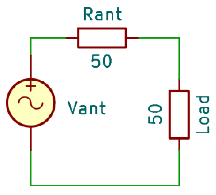
is the maximum power that can be received from the antenna and delivered to the energy harvester. It is equal to the real power available in the circuit only when the connection between the antenna and the energy harvesting module is perfectly balanced energetically [
22]. This occurs if the load value is equal to the characteristic impedance of the antenna.
Figure 1 presents a case wherein the antenna has 50
of impedance.
It can be easily calculated that the maximum possible power transfer from the antenna to the load is equal according to (
2).
The maximum directivity of each antenna is in relation to its maximum aperture
. The aperture of the antenna is the area through which waves travel to and from space [
23]. When free space is assumed together with a perfectly matched lossless antenna, the power available in the circuit is described by the Friis equation [
22] shown in (
3).
The coefficients used in Equation (
3) are:
d—antenna’s directivity;
—free-space equation;
—maximum antenna directivity;
—effective radiated power.
The directivity mentioned in (
3)
d describes the relation between the radiation of the antenna in a given direction compared to that of an isotropic antenna.
The practical appliance of the Friis equation looks as follows:
where the symbols are
| power at the receiver antenna; |
| power of the transmitter antenna; |
| gain of the receiver antenna with respect to an isotropic one; |
| gain of the transmitter antenna with respect to an isotropic one; |
| longitude of the wave; |
| d | distance between transmitter and receiver. |
And the practical logarithmic version expressed in dBm and dBi units is as below:
The power in dBm units is defined as:
The dBi units express in logarithmic scale the gain of an antenna compared to that of the ideal isotropic antenna. It is assumed that the isotropic antenna has a reference 0 dB gain value.
5. Estimated Power Available in the Harvester from LTE Base Stations
Equation (
5) presented above can be used to calculate the power available to a receiver in a field generated by an LTE base station. The following devices have been selected as reference devices to assume the parameters of the wireless channel. The parameters of the LTE 800 MHz band are: an Ericsson 1001 1 L 0 M 2.3 m antenna is selected as a reference for source simulation purposes. It has a gain of up to 20.5 dBi according to its data sheet [
24]. A 38 dBm transmitter power in accordance with the 3GPP documentation TS 136.104 is assumed [
25]. The parameters of a Signaflex THUNDER antenna are taken to simulate the receiver. It has a gain equal to 20 dBi [
26]. The above configuration gives the power available at the receiving antenna as ca. 21 dBm according to Equation (
5) at a distance of 20 m, which gives approximately 1.83 V at the output of the antenna when loaded with characteristic impedance. More detailed calculations are given in
Table 1.
A range of 20 m around the source of the beam seems to give satisfying conditions for rectifier construction; however, such a distance is problematic in practise. Definitely more realistic are distances of dozens of meters and an induced voltage of fractions of 1 V, which leads to more advanced difficulties for designing the harvester. The basic issue is that the most popular elements of rectifiers, Schottky diodes, consume some amount of voltage. Therefore, some solutions are needed to increase the voltage.
A popular method involves an L-type circuit with a capacitor and a coil. Both elements, if ideal, do not consume energy, so they seem to be perfect for mediation in energy transfer. When there is a need to increase the voltage during a transfer, series LC resonance is helpful.
The power received by the load is equal to:
. The maximum value of the transferred power determines (
2). So, the optimum case describes the condition (
7).
Hence, the Formula (
8) shows a relation between the voltage gain
of the circuit and the resistances
and
:
which assures keeping the maximal transfer of energy. The efficiency of the circuit
(
9)—denoted as the maximum possible power to transfer from the antenna
(
2) to the power received by the load
—is:
and in this case, it is equal to 100%.
6. RF Energy Harvester Simulation
Based on the knowledge presented in
Section 4 and
Section 5 on the energy transferred with electromagnetic waves, a circuit that simulates RF energy harvesting may be proposed. The common use of radio frequencies makes them a perfect candidate for the source of energy that must be harvested from the environment. However, conducting experiments with RFs is difficult. This is why the possibility of simulating circuits operating at such frequencies is crucial for conducting research. Simulation makes it possible to test and develop modules and verify the impact of particular elements on the whole harvester. In this paper, three environments are compared. The first is KiCad EDA. This GNU GPL v.3 or higher licensed program is a free solution that is widely used for designing electronic modules. It includes integrated simulation software: NGSPICE. The second environment is LT Spice, which is designed to test electronic modules. It is publicly available thanks to Analog Devices and contains a large database of electronic parts that can be used in prototyping. The last program is Simscape Electrical, which is part of the MATLAB Simulink environment. In this paper, the same circuit was simulated in all environments, and the results are compared.
6.1. Circuit Model
In all three environments, the same circuits were modelled using the conditions found in
Section 5. At first, a simple resonator as proposed in
Figure 2 was tested. It is a simple RF energy harvester that converts the energy received in the antenna into the current in the load. The antenna receiving the signal is modelled as a Thevenin’s equivalent voltage source with a resistance of 50
. The voltage source models a receiving antenna in which voltage is excited by RF waves. It is followed by an impedance-matching network that makes sure the maximum possible amount of energy is transferred from the antenna to the harvester module. The circuit is closed with a 5 kΩ load. This can represent the end device, such as a battery charging module. This circuit is presented in
Figure 3 as designed for KiCad EDA, in
Figure 4 for LT Spice, and in
Figure 5 for Simscape Electrical. In this circuit, all elements are ideal ones taken from the default SPICE libraries. All the figures just mentioned are actual screenshots from the programs and show the differences in the Graphical User Interfaces and representations of particular elements. It was decided to present the screenshots here for ease of understanding the schemes, and as manipulating the models may be important for further research.
In the next step, the circuitry was extended by adding a simple rectifier part. This design does not present the ideal harvester but gives the possibility to verify the impact of a particular diode’s parameters on the performance. In the designs below (
Figure 6,
Figure 7 and
Figure 8), a particular diode model was used: HSMS_2851 [
27]. It is a Schottky diode that has a particularly low switch time. Hence, it can be used in high-frequency applications of up to 1 GHz, as checked in [
28] for a model up to 900 MHz. For other electronic parts, the default ideal models available in the SPICE databases were used.
6.2. Simulation
The models presented in the above section were used to conduct simulations in all three environments. In both KiCad EDA and LT Spice, the simulation time was set to 10 ns and the simulation step was set to 10 ps. In Simscape Electrical, the simulation time was also set to 10 ns, but the simulation step was set automatically by the environment. We conducted three simulations:
Ideal resonator—to verify if output voltage will be boosted in comparison to the one on the antenna;
Harvester with diode with zero internal capacitance—to provide reference results;
Harvester with real diode model—to check the impact of the internal capacitance on the current in the diode.
For an ideal resonator, results presenting both the input and output voltages and currents in the load are presented. All results were analysed in MATLAB.
Figure 9 shows the results from simulation in KiCad EDA.
Figure 10 presents the same relations for LT Spice, and
Figure 11 presents the results for Simscape Electrical.
Also, data regarding the current in the load were collected for every environment. Current measured in KiCad was presented in
Figure 12, LT Spice–
Figure 13 and in Simscape Electrical in
Figure 14.
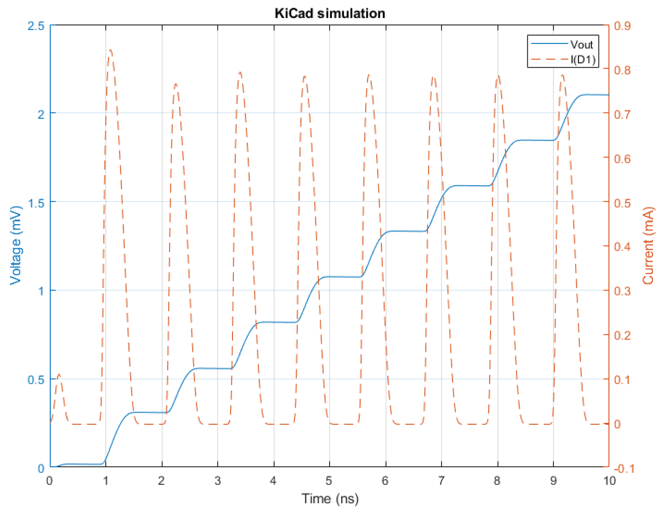
Ideal resonator simulations were followed by simulations of a simple harvester circuit with a diode with zero internal capacitance. The simulation results are presented as graphs consisting of an axis with the simulation time and the voltage on the load and the current in the diode represented by D1 in the designs. The results of KiCad EDA are presented in
Figure 15, LT Spice is in
Figure 16, and Simscape Electrical is in
Figure 17.
The final simulations were done using a real diode model.
Figure 18,
Figure 19 and
Figure 20 show the results for KiCad EDA, LT Spice and Simscape Electrical, correspondingly.
The conducted experiments shows that it is possible to analytically find a perfect impedance-matching network for an antenna–load circuit. However, adding any elements after the resonator causes the perfect match to be lost, and therefore, it is difficult to transfer all the available power from the antenna to the harvester circuit.
Simulation results showed how the diode’s internal capacitance influences the output voltage and current in the diode. Comparing
Figure 15,
Figure 16 and
Figure 17 with
Figure 18,
Figure 19 and
Figure 20, one can see that the presence of internal capacitance in the diode has a significant impact on the operation in the upper sub-1 GHz frequencies. It makes the diode have a slight back-current that effectively decreases the output voltage and the power available to the load of the circuit.
Results analysis shows that simulations in all environments are comparable. The outcomes from the last simulation were imported to and presented in MATLAB based on the collected numerical values. This program allows us to easily manipulate and analyse data. It was observed that for the assumed parameters, the simulation results differed in the number of collected samples. In KiCad EDA, there were 1009 value sets; in LT Spice, there were 895 sets; in Simscape Electrical, there were 231 value sets. The outcomes are compared in
Table 2. Values are purposefully provided in the same exact notation as in the MATLAB analysis to provide insight into the numerical differences for the particular environments.
The results differ just slightly. Those differences may be the result of different numbers of samples collected, which correspond to different moments in simulation time. It means that the particular outliers may be shifted between simulations.
7. Summary
This paper presents fundamental concepts standing behind RF energy harvesting. The state of the research in the area was covered. Existing commercial products were briefly introduced. The design of a simple RF energy harvester model was presented. It was further used to conduct simulations in conditions similar to those of an LTE mobile network. Three different simulation environments were compared: KiCad EDA, LT Spice and Simscape Electrical. The first two are well known in research and design; the latter one is less popular. The outcomes of the simulations showed that Simscape Electrical provides the same accuracy as the other environments. However, it provides a large variety of additional tools that help to analyse the results and to design the modules. Furthermore, MATLAB provides a wide choice of libraries for researching radio frequencies. Therefore, it will be used in further research on this topic.
During the research for this paper, we noticed that for the proposed frequencies, the diode’s capacitance plays a crucial role in harvester performance.
Research on RF energy harvesting will continue. The next steps are to propose a simulation design that is capable of harvesting energy not only from a single frequency but for a given bandwidth. This will allow for harvesting of all the energy that is used during communication in a mobile network. The next change to the design that will be tested will be to introduce a varying internal resistance in the voltage source that changes with the load. This will much better represent a real device and should increase the amount of energy available in the circuit. Also, a study on other radio frequency sources will be considered in order to find the one that provides the biggest amount of energy in a narrower band. Further, the concept of RF energy harvesting in a lossless environment such as outer space will be considered. In the end, a comparison of simulation and real-life hardware results should be done.
One of the real applications that was brought up during research was to use an RF energy harvester to power an ultra-low-power ARM Cortex-M0+ MCU [
29]. It is an ultra-low-power microprocessor for which the power consumption requirements meet the power available from RF energy harvesting modules. Using such a device can be the first step in creating RF-energy-powered sensors.
Author Contributions
Conceptualisation: M.P., P.P. and J.S.; methodology: M.P. and P.P. formal analysis: M.P. and P.P.; funding acquisition: P.P.; investigation: J.S. and M.P.; resources: M.P. and J.S.; software: M.P.; data curation: J.S.; supervision: P.P.; validation: M.P. and P.P.; writing—original draft: J.S.; writing—review & editing M.P., P.P. and J.S. All authors have read and agreed to the published version of the manuscript.
Funding
This work was funded from AGH University of Krakow subvention for scientific activity no. 16.16.120.773.
Data Availability Statement
The data presented in this study are available on request from the corresponding authors.
Conflicts of Interest
The authors declare no conflicts of interest.
References
- Tesla, N. The transmission of electric energy without wires. Sci. Am. 1904, 57, 23760–23761. [Google Scholar] [CrossRef]
- Flowers, A.E. Crystal and solid contact rectifiers. Phys. Rev. (Ser. I) 1909, 29, 445–460. [Google Scholar] [CrossRef]
- Eid, A.; Hester, J.G.D.; Tentzeris, M.M. 5G as a wireless power grid. Sci. Rep. 2021, 11, 636. [Google Scholar] [CrossRef] [PubMed]
- Amjad, M.; Chughtai, O.; Naeem, M.; Ejaz, W. SWIPT-Assisted Energy Efficiency Optimization in 5G/B5G Cooperative IoT Network. Energies 2021, 14, 2515. [Google Scholar] [CrossRef]
- Chen, M.-C.; Sun, T.-W.; Tsai, T.-H. Dual-Domain Maximum Power Tracking for Multi-Input RF Energy Harvesting with a Reconfigurable Rectifier Array. Energies 2022, 15, 2068. [Google Scholar] [CrossRef]
- Katbay, Z.; Sounas, D.; Ismail, M. Scatterers in the Rx Near Field for RF Energy Harvesting Efficiency Enhancement. Energies 2022, 15, 2109. [Google Scholar] [CrossRef]
- Nwalike, E.D.; Ibrahim, K.A.; Crawley, F.; Qin, Q.; Luk, P.; Luo, Z. Harnessing Energy for Wearables: A Review of Radio Frequency Energy Harvesting Technologies. Energies 2023, 16, 5711. [Google Scholar] [CrossRef]
- Dziadak, B.; Makowski, Ł.; Kucharek, M.; Jóśko, A. Energy Harvesting for Wearable Sensors and Body Area Network Nodes. Energies 2023, 16, 1681. [Google Scholar] [CrossRef]
- Ipar, P.E.; Lambor, S.M.; Joshi, S.M. Development of radio frequency energy harvesting module. In Proceedings of the 2016 IEEE Annual India Conference (INDICON), Bangalore, India, 16–18 December 2016. [Google Scholar]
- Powercast. PCC110/PCC210-Powercast, Powerharvester® RF-to-DC Converter Chip. 2024. Available online: https://powercastco.com/wp-content/uploads/2021/06/PCC110-PCC210-Overview-V1.6-ONE-PAGE-1.pdf (accessed on 3 January 2024).
- Powercast. Solving Real-World Wireless Charging Challenges Since 2007. Available online: https://www.powercastco.com/about/#:~:text=Solving%20real%2Dworld%20wireless%20charging%20challenges%20since%202007%3A&text=Along%20the%20way%2C%20the%20company,awards%2Fand%2021%20patents%20pending (accessed on 28 January 2024).
- Powercast. About PowerCast. 2023. Available online: https://www.powercastco.com/ces-2023/ (accessed on 28 January 2024).
- Powercast. TX91501B-Powercast, 915 MHz Powercaster® Transmitter. 2024. Available online: https://www.powercastco.com/wp-content/uploads/2021/06/User-Manual-TX-915-01B-Rev-A-1.pdf (accessed on 3 January 2024).
- e-peas. RF Energy Harvesting: Radio Frequency Power Harvester. Available online: https://e-peas.com/energy-harvesting/rf/ (accessed on 28 January 2024).
- e-peas. EP112-e-peas, High Efficiency RF Harvesting Antenna. 2024. Available online: https://e-peas.com/wp-content/uploads/2023/05/e-peas_Product_Brief_EP112_RF_energy_harvesting-1.pdf (accessed on 3 January 2024).
- e-peas. AEM30940-e-peas, Highly Efficient, Regulated Dual-Output, Ambient Energy Manager for AC or DC Sources with Optional Primary Battery. 2024. Available online: https://e-peas.com/wp-content/uploads/2022/09/e-peas-AEM30940-datasheet-RF-Vibration-energy-harvesting-09-22.pdf (accessed on 3 January 2024).
- Energous. 1W WattUp® Powerbridge for Wiliot IOT Pixels. Available online: https://energous.com/wp-content/uploads/2023/06/WattUp_PowerBridge_WorksWithWiliot_ProductBrief_Mar022023.pdf (accessed on 28 January 2024).
- Guruwireless. Guru and Motorola to Bring First Over-the-Air, Wirelessly Powered Technology. Available online: https://www.prnewswire.com/news-releases/guru-and-motorola-to-bring-first-over-the-air-wirelessly-powered-technology-301289518.html (accessed on 28 January 2024).
- Ossia Inc. Wireless Charging ‘Forever Battery’ Offers Innovative AA Battery Replacement. Available online: https://www.ossia.com/news/wireless-charging-forever-battery-offers-innovative-aa-battery-replacement (accessed on 28 January 2024).
- Powercast. P2110B, 915 MHz RF Powerharvester® Receiver. 2024. Available online: https://www.powercastco.com/wp-content/uploads/2021/06/P2110B-Datasheet-Rev-3.pdf (accessed on 3 January 2024).
- Visser, H.J.; Vullers, R.J. RF Energy Harvesting and Transport for Wireless Sensor Network Applications: Principles and requirements. Proc. IEEE 2013, 101, 1410–1423. [Google Scholar] [CrossRef]
- Serdijn, W.A.; Mansano, A.L.R.; Stoopman, M. Introduction to RF energy harvesting. In Wearable Sensors; Academic Press: San Diego, CA, USA, 2014; pp. 299–322. [Google Scholar] [CrossRef]
- Balanis, C.A. Antenna Theory: Analysis and Design; Wiley Blackwell: Hoboken, NJ, USA, 2016. [Google Scholar]
- Ericsson. Antenna 1001 1L 0M 2.3m. 2023. Available online: https://www.ericsson.com/en/antenna-system (accessed on 28 January 2024).
- ETSI. TS 136 104 BS Radio Transmission and Reception 2017. January 2017. Available online: https://www.etsi.org/deliver/etsi_ts/136100_136199/136104/13.06.00_60/ts_136104v130600p.pdf (accessed on 28 January 2024).
- Signaflex. Antena Signaflex Thunder. 2023. Available online: http://www.signaflex.pl/antena-kierunkowa-thunder-20dbi-4g-lte.html (accessed on 31 May 2023).
- Avago Technologies. HSMS-285X Series Surface Mount Zero Bias Schottky Detector Diodes. 2009. Available online: https://media.digikey.com/pdf/Data%20Sheets/Avago%20PDFs/HSMS-285x.pdf (accessed on 28 January 2024).
- Taris, T.; Vigneras, V.; Fadel, L. A 900 MHz RF energy harvesting module. In Proceedings of the 10th IEEE International NEWCAS Conference, Montreal, QC, Canada, 17–20 June 2012; pp. 445–448. [Google Scholar] [CrossRef]
- STMicroelectronics. STM32L051K6, Ultra-Low-Power Arm Cortex-M0+ MCU with 32 Kbytes of Flash Memory, 32 MHz CPU. 2024. Available online: https://www.st.com/en/microcontrollers-microprocessors/stm32l051k6.html (accessed on 3 January 2024).
Figure 1.
Balanced load of the antenna.
Figure 1.
Balanced load of the antenna.
Figure 2.
Transfer energy with increasing voltage.
Figure 2.
Transfer energy with increasing voltage.
Figure 3.
Energy resonator model designed in KiCad EDA.
Figure 3.
Energy resonator model designed in KiCad EDA.
Figure 4.
Energy resonator model designed in LT Spice.
Figure 4.
Energy resonator model designed in LT Spice.
Figure 5.
Energy resonator model designed in Simscape Electrical.
Figure 5.
Energy resonator model designed in Simscape Electrical.
Figure 6.
RF energy harvester model designed in KiCad EDA.
Figure 6.
RF energy harvester model designed in KiCad EDA.
Figure 7.
RF energy harvester model designed in LT Spice.
Figure 7.
RF energy harvester model designed in LT Spice.
Figure 8.
RF energy harvester model designed in Simscape Electrical.
Figure 8.
RF energy harvester model designed in Simscape Electrical.
Figure 9.
Input and output voltages for ideal resonator as simulated in KiCad EDA.
Figure 9.
Input and output voltages for ideal resonator as simulated in KiCad EDA.
Figure 10.
Input and output voltages for ideal resonator as simulated in LT Spice.
Figure 10.
Input and output voltages for ideal resonator as simulated in LT Spice.
Figure 11.
Input and output voltages for ideal resonator as simulated in Simscape Electrical.
Figure 11.
Input and output voltages for ideal resonator as simulated in Simscape Electrical.
Figure 12.
Current in load for ideal resonator as simulated in KiCad EDA.
Figure 12.
Current in load for ideal resonator as simulated in KiCad EDA.
Figure 13.
Current in load for ideal resonator as simulated in LT Spice.
Figure 13.
Current in load for ideal resonator as simulated in LT Spice.
Figure 14.
Current in load for ideal resonator as simulated in Simscape Electrical.
Figure 14.
Current in load for ideal resonator as simulated in Simscape Electrical.
Figure 15.
Results of time simulation for KiCad EDA. The full line shows the voltage on the load, and the dashed line shows the current in the D1 diode.
Figure 15.
Results of time simulation for KiCad EDA. The full line shows the voltage on the load, and the dashed line shows the current in the D1 diode.
Figure 16.
Results of time simulation for LT Spice. The full line shows the voltage on the load, and the dashed line shows the current in the D1 diode.
Figure 16.
Results of time simulation for LT Spice. The full line shows the voltage on the load, and the dashed line shows the current in the D1 diode.
Figure 17.
Results of time simulation for Simscape Electrical. The full line shows the voltage on the load, and the dashed line shows the current in the D1 diode.
Figure 17.
Results of time simulation for Simscape Electrical. The full line shows the voltage on the load, and the dashed line shows the current in the D1 diode.
Figure 18.
Results of time simulation for KiCad EDA using a real diode. The full line shows the voltage on the load, and the dashed line shows the current in the D1 diode.
Figure 18.
Results of time simulation for KiCad EDA using a real diode. The full line shows the voltage on the load, and the dashed line shows the current in the D1 diode.
Figure 19.
Results of time simulation for LT Spice using a real diode. The full line shows the voltage on the load, and the dashed line shows the current in the D1 diode.
Figure 19.
Results of time simulation for LT Spice using a real diode. The full line shows the voltage on the load, and the dashed line shows the current in the D1 diode.
Figure 20.
Results of time simulation for Simscape Electrical using a real diode. The full line shows the voltage on the load, and the dashed line shows the current in the D1 diode.
Figure 20.
Results of time simulation for Simscape Electrical using a real diode. The full line shows the voltage on the load, and the dashed line shows the current in the D1 diode.
Table 1.
Distribution of power available at the receiver antenna (gain = 20 dBi) vs. the distance from the sending antenna (gain = 20.5 dBi) for 868 MHz () frequency band and emitted power equal to 38 dBm. Impedance of the antennas: 50 .
Table 1.
Distribution of power available at the receiver antenna (gain = 20 dBi) vs. the distance from the sending antenna (gain = 20.5 dBi) for 868 MHz () frequency band and emitted power equal to 38 dBm. Impedance of the antennas: 50 .
| Distance [m] | Receiving Power [dBm] | Receiving Voltage [V] |
|---|
| 10 | 27.99 | 3.66 |
| 15 | 23.77 | 2.44 |
| 20 | 21.27 | 1.83 |
| 50 | 13.31 | 0.73 |
| 100 | 7.28 | 0.37 |
Table 2.
Numerical results comparison for all environments.
Table 2.
Numerical results comparison for all environments.
| | Simscape Electrical | LT Spice | KiCad |
|---|
| Number of samples | 231 | 895 | 1009 |
| Minimum voltage [V] | | | |
| Maximum voltage [V] | 0.0016 | 0.0016 | 0.0016 |
| Minimum current [A] | | | |
| Maximum current [A] | | | |
| Disclaimer/Publisher’s Note: The statements, opinions and data contained in all publications are solely those of the individual author(s) and contributor(s) and not of MDPI and/or the editor(s). MDPI and/or the editor(s) disclaim responsibility for any injury to people or property resulting from any ideas, methods, instructions or products referred to in the content. |
© 2024 by the authors. Licensee MDPI, Basel, Switzerland. This article is an open access article distributed under the terms and conditions of the Creative Commons Attribution (CC BY) license (https://creativecommons.org/licenses/by/4.0/).


