
Concept and Design of a Velocity Compounded Radial Four-Fold Re-Entry Turbine for Organic Rankine Cycle (ORC) Applications

 , and
, and
Abstract
1. Introduction

| Reference | Working Fluid | Turbine Type | PR | Pel [kW] | ηis [%] |
|---|---|---|---|---|---|
| Kaczmarczyk et al. [9] Zywica et al. [14,15] | HFE7100 HFE7100 | 4-stage radial axial | 7 3.1 | 2 1 | 70 73 |
| Riffat & Zhao [16] | n-pentane | Axial | 5 | 3.7 | n.a. |
| Hernandez-Carillo [17] | R245fa | Radial inflow | n.a. | 1.2 | 66 |
| Pu et al. [18] | R245fa; HFE7100 | Axial | 3.5 | 2 | 60 |
| Li et al. [19] | R123 | Axial | 6.3 | 6.1 | 58.5 |
| Pei et al. [20] | R123 | Radial inflow | 7.5 | 3.3 | 66 |
| Nguyen et al. [21] | n-pentane | Radial inflow | 4.1 | 1.5 | 50 |
| Yagoub et al. [22] | HFE-301 | Radial inflow | n.a. | 1.5 | 85 * |
| Yagoub et al. [22] | n-pentane | Radial inflow | n.a. | 1.5 | 40 |
| Klonowicz et al. [23] | R227ea | Axial impulse | 2.9 | 10.1 | 59 |
| Shao et al. [24] | R123 | Radial inflow | 3 | 3.4 | 83.6 * |
| Seume et al. [25] | Ethanol | Axial impulse | 50 | 8 | 58 |
| Kosowski et al. [26] | Ethanol | Axial impulse | 17.3 | 2 | n.a. |
| Weiß et al. [7] | MM | Axial impulse; radial cantilever | 18.8 | 14.1 16 | 73.4; 76.8 |
| Rosset et al. [27] | R245fa | Radial inflow | 3–4.5 | 2.3 | 77 |
| Popp et al. [10] | MM | Radial cantilever | 14 | 12 | 64 |
| Uusitalo et al. [8] | MDM | Radial inflow | 60–80 | 10 | 70 |
| Gazet et al. [28] | HFE | Axial impulse | 3 | 10 | 70 |
| Yue et al. [29] | R245fa | Axial | n.a. | 5 | 56.4 |
| Guillaume et al. [30] | R1233zd | Radial inflow | 4 | 3.5 | 75 |
| Demierre et al. [31] | R134a | Radial inflow | 4.3 | 2.4 | 67 |
| Cho et al. [32] | R245fa | Axial | 4.8 | 2.2 | n.a. |
| Al Jubori et al. [33] | various | Radial inflow | 1.2–2.2 | 4.8 | 78.3 |
| Bahamonde et al. [12] | MM | Radial outflow | 35.2 | 10 | 68.7 |
| Casati et al. [13] | D4 | Radial outflow | 45 | 10.3 | 77 |
| Sun et al. [11] | R1233zde | Axial impulse Partially admitted | 3.5 | 0.6 | 35.8 |
- Is it feasible to develop an ORC-Elektra turbine that drives an off-the-shelf (i.e., standard) generator operating within the range of 1500–3000 rpm and delivers an isentropic expansion efficiency of at least 50%? The initial Elektra designs from the early 20th century that operated with steam, as documented [43,44], achieved efficiencies significantly below 50% for power ratings exceeding 30 kW. Nevertheless, the researchers of that era did not have access to today’s computational fluid dynamic (CFD) tools, which are expected to offer significant room for improvements, especially in the design of deflection channels.
- Is it possible to significantly reduce the manufacturing and operational costs of a small-scale ORC expanders thanks to the velocity-compounding RFFRE-T (i.e., Elektra) concept? The Elektra turbine combines the advantages of volumetric expanders (the low rotational speed requirement) with the advantages of a turbine (no rubbing seals, no lubrication in the working fluid, wear is almost completely avoided, etc. [6]).
- What is the lowest power rating at which the above-mentioned objectives can be met effectively?
2. Methodology
2.1. 1D Turbine Design
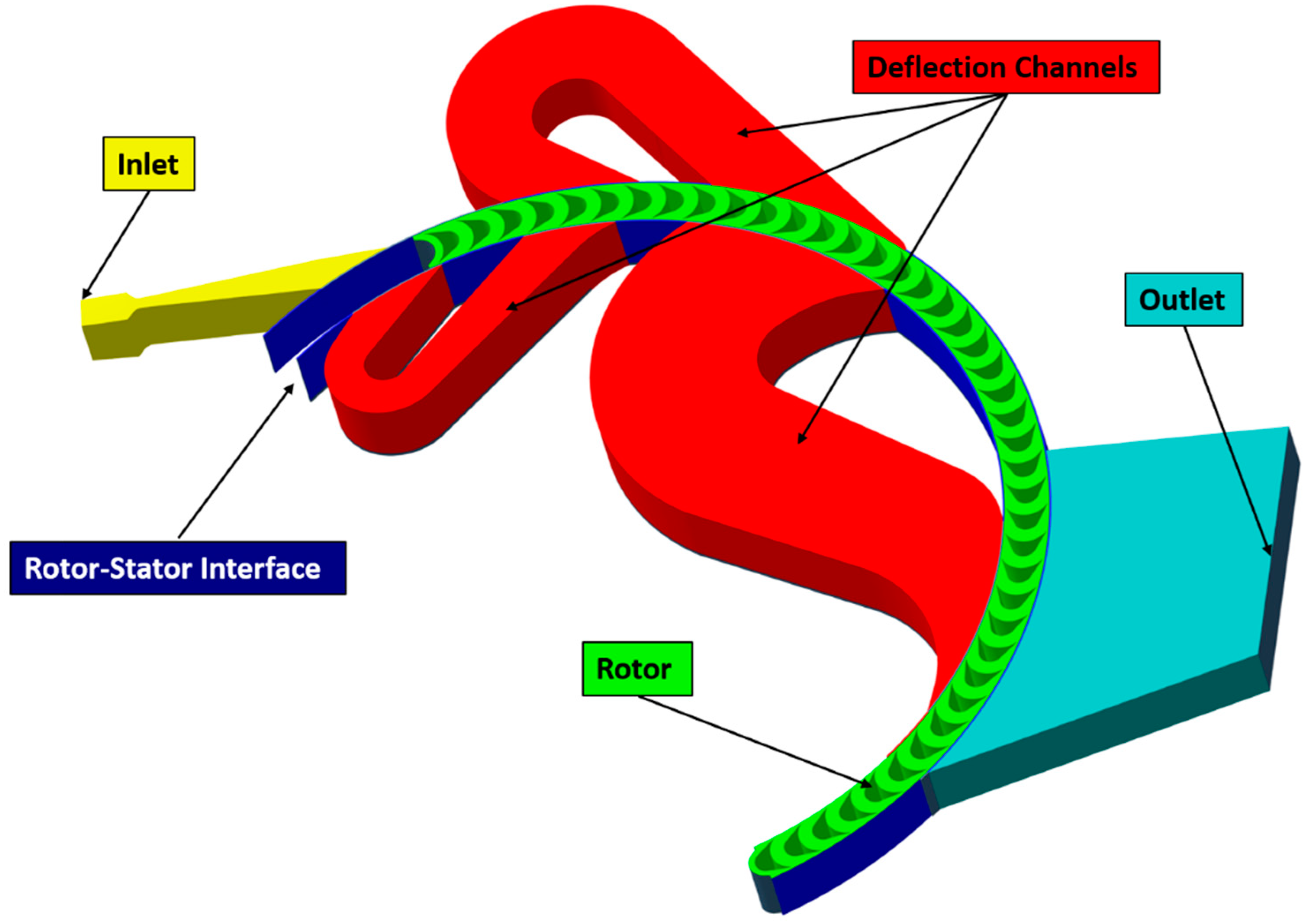
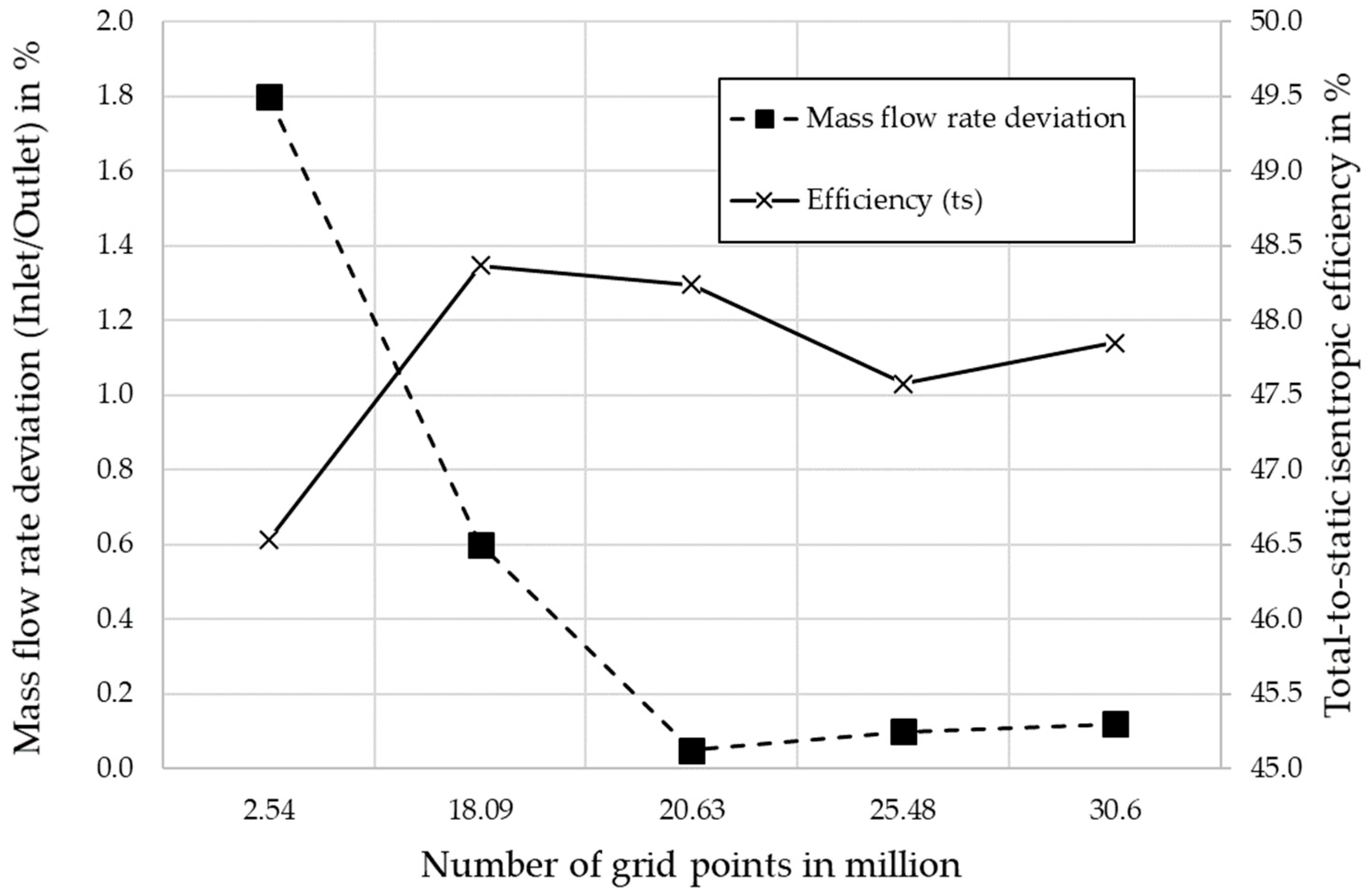
2.2. CFD Settings
2.3. Initial Turbine Design Data
2.4. CFD Turbine Optimization
3. Results
4. Discussion
5. Conclusions
Author Contributions
Funding
Data Availability Statement
Conflicts of Interest
Nomenclature
| A | area (mm2) |
| β | relative flow angle (°) |
| c | absolute velocity (m·s−1) |
| Δ | difference (1) |
| D | diameter (mm) |
| ε | degree of admission (%) |
| h | specific enthalpy (J·kg−1) |
| h | blade height (mm) |
| η | efficiency (%) |
| n | rotational speed (rpm) |
| p | pressure (Pa) |
| T | temperature (K) |
| P | power (kW) |
| u | circumferential velocity (m·s−1) |
| w | relative velocity (m·s−1) |
| Subscripts | |
| el | electrical |
| is | isentropic |
| in | inner |
| opt | optimum |
| out | outer, outlet |
| ts | total-to-static |
| 0 | total |
| rel | relative |
| Abbreviations | |
| CAD | computer aided design |
| CD | convergent-divergent |
| CFD | computational fluid dynamics |
| CHP | combined heat and power |
| CSP | concentrated solar power |
| DC | deflection channel |
| IGG | internal grid generator |
| MM | hexamethyldisiloxane |
| MS | Microsoft |
| MTG-c | micro turbine generator construction |
| ORC | Organic Rankine cycle |
| P2H2P | power to heat to power |
| PR | pressure ratio |
| RANS | Reynolds averaged Navier Stokes |
| ROT | Radial outflow turbine |
| RE | Re-entry |
| RFFRE-T | Radial four fold re-entry turbine |
| SA | Spalart-Allmaras |
| VRAT | volume flow ratio |
| WHR | waste heat recovery |
| WP | wheel pass |
| 1D | one dimensional |
| 1DTDT | one dimensional turbine design tool |
| 3D | three dimensional |
References
- Meher-Homji, C.B. The Historical Evolution of Turbomachinery. In Proceedings of the 29th Turbomachinery Symposium 2000, Houston, TX, USA, 29 September 2000; pp. 281–322. [Google Scholar] [CrossRef]
- Tartière, T.; Astolfi, M. A World Overview of the Organic Rankine Cycle Market. Energy Procedia 2017, 129, 2–9. [Google Scholar] [CrossRef]
- Tocci, L.; Pal, T.; Pesmazoglou, I.; Franchetti, B. Small Scale Organic Rankine Cycle (ORC): A Techno-Economic Review. Energies 2017, 10, 413. [Google Scholar] [CrossRef]
- Lemort, V.; Ludovic, G.; Arnaud, L.; Declaye, S.; Quoilin, S. A comparison of piston, screw and scroll expander for small Rankine cycle systems. In Proceedings of the 3rd International Conference on Microgeneration and Related Technologies, Naples, Italy, 15–17 April 2013. [Google Scholar]
- Glavatskaya, Y.; Podevin, P.; Lemort, V.; Shonda, O.; Descombes, G. Reciprocating Expander for an Exhaust Heat Recovery Rankine Cycle for a Passenger Car Application. Energies 2012, 5, 1751–1765. [Google Scholar] [CrossRef]
- Weiß, A.P. Volumetric expander versus turbine—Which is the better choice for small ORC plants? In ASME-ORC2015, Proceedings of the 3rd International Seminar on ORC Power Systems, Brussels, Belgium, 12–14 October 2015; University of Liège: Liège, Belgium; Ghent University: Ghent, Belgium, 2015; ISBN 978-2-9600059-2-9. [Google Scholar]
- Weiß, A.P.; Popp, T.; Müller, J.; Hauer, J.; Brüggemann, D.; Preißinger, M. Experimental characterization and comparison of an axial and a cantilever micro-turbine for small-scale Organic Rankine Cycle. Appl. Therm. Eng. 2018, 140, 235–244. [Google Scholar] [CrossRef]
- Uusitalo, A.; Zocca, M.; Turunen-Saaresti, T. Measurement System of Small-Scale High Expansion Ratio ORC Turbine; Springer: Berlin/Heidelberg, Germany, 2021; pp. 114–122. [Google Scholar]
- Kaczmarczyk, T.Z.; Żywica, G.; Ihnatowicz, E. Experimental Investigation of a Radial Microturbine in Organic Rankine Cycle System with HFE7100 as Working Fluid. In Proceedings of the 3rd International Seminar on ORC Power Systems, Brussels, Belgium, 12–14 October 2015; pp. 1–10. [Google Scholar]
- Popp, T.; Weiß, A.P.; Heberle, F.; Winkler, J.; Scharf, R.; Weith, T.; Brüggemann, D. Experimental Characterization of an Adaptive Supersonic Micro Turbine for Waste Heat Recovery Applications. Energies 2021, 15, 25. [Google Scholar] [CrossRef]
- Sun, H.; Li, H.; Gao, P.; Hou, F.; Hung, T.-C.; Chang, Y.-H.; Lin, C.-W.; Qin, J. Numerical simulation and low speed experiment of a low partially admitted rate axial turbine for small scale organic Rankine cycle. Appl. Therm. Eng. 2024, 238, 122002. [Google Scholar] [CrossRef]
- Bahamonde, S.; Pini, M.; de Servi, C.; Rubino, A.; Colonna, P. Method for the Preliminary Fluid Dynamic Design of High-Temperature Mini-Organic Rankine Cycle Turbines. J. Eng. Gas Turbines Power 2017, 139, 082606. [Google Scholar] [CrossRef]
- Casati, E.; Vitale, S.; Pini, M.; Persico, G.; Colonna, P. Centrifugal Turbines for Mini-Organic Rankine Cycle Power Systems. J. Eng. Gas Turbines Power 2014, 136, 122607. [Google Scholar] [CrossRef]
- Żywica, G.; Kaczmarczyk, T.; Ihnatowicz, E.; Bagiński, P.; Andrearczyk, A. Design and manufacturing of micro-turbomachinery components with application of heat resistant plastics. Mech. Mech. Eng. 2018, 22, 649–660. [Google Scholar] [CrossRef]
- Żywica, G.; Kaczmarczyk, T.Z.; Breńkacz, Ł.; Bogulicz, M.; Andrearczyk, A.; Bagiński, P. Investigation of dynamic properties of the microturbine with a maximum rotational speed of 120 krpm—Predictions and experimental tests. J. Vibroeng. 2020, 22, 298–312. [Google Scholar] [CrossRef]
- Riffat, S.B.; Zhao, X. A novel hybrid heat-pipe solar collector/CHP system—Part II: Theoretical and experimental investigations. Renew. Energy 2004, 29, 1965–1990. [Google Scholar] [CrossRef]
- Hernandez-Carrillo, I.; Wood, C.; Liu, H. Development of a 1000 W organic Rankine cycle micro-turbine-generator using polymeric structural materials and its performance test with compressed air. Energy Convers. Manag. 2019, 190, 105–120. [Google Scholar] [CrossRef]
- Pu, W.; Yue, C.; Han, D.; He, W.; Liu, X.; Zhang, Q.; Chen, Y. Experimental study on Organic Rankine cycle for low grade thermal energy recovery. Appl. Therm. Eng. 2016, 94, 221–227. [Google Scholar] [CrossRef]
- Li, M.; Wang, J.; He, W.; Gao, L.; Wang, B.; Ma, S.; Dai, Y. Construction and preliminary test of a low-temperature regenerative Organic Rankine Cycle (ORC) using R123. Renew. Energy 2013, 57, 216–222. [Google Scholar] [CrossRef]
- Pei, G.; Li, J.; Li, Y.; Wang, D.; Ji, J. Construction and dynamic test of a small-scale organic rankine cycle. Energy 2011, 36, 3215–3223. [Google Scholar] [CrossRef]
- Nguyen, V.M.; Doherty, P.S.; Riffat, S.B. Development of a prototype low-temperature Rankine cycle electricity generation system. Appl. Therm. Eng. 2001, 21, 169–181. [Google Scholar] [CrossRef]
- Yagoub, W.; Doherty, P.; Riffat, S.B. Solar energy-gas driven micro-CHP system for an office building. Appl. Therm. Eng. 2006, 26, 1604–1610. [Google Scholar] [CrossRef]
- Klonowicz, P.; Heberle, F.; Preißinger, M.; Brüggemann, D. Significance of loss correlations in performance prediction of small scale, highly loaded turbine stages working in Organic Rankine Cycles. Energy 2014, 72, 322–330. [Google Scholar] [CrossRef]
- Shao, L.; Zhu, J.; Meng, X.; Wei, X.; Ma, X. Experimental study of an organic Rankine cycle system with radial inflow turbine and R123. Appl. Therm. Eng. 2017, 124, 940–947. [Google Scholar] [CrossRef]
- Seume, J.R.; Peters, M.; Kunte, H. Design and test of a 10 kW ORC supersonic turbine generator. J. Phys. Conf. Ser. 2017, 821, 12023. [Google Scholar] [CrossRef]
- Kosowski, K.; Piwowarski, M.; Stepień, R.; Włodarski, W. Design and investigations of the ethanol microturbine. Arch. Thermodyn. 2018, 39, 41–54. [Google Scholar] [CrossRef]
- Rosset, K.; Pajot, O.; Schiffmann, J. Experimental investigation of a small-scale organic rankine cycle turbo-generator supported on gas-lubricated bearings. J. Eng. Gas Turbines Power 2021, 143, 051015. [Google Scholar] [CrossRef]
- Gazet, C.; Leroux, A.; Paillette, B.; Pauchet, A. Operational experience on ORC use for waste heat valorization in biogas power plant. In Proceedings of the 3rd International Seminar on ORC Power Systems, Brussels, Belgium, 12–14 October 2015; pp. 1–7. [Google Scholar]
- Yue, C.; Huang, Y.; Wu, Y. Experimental Study of Low-temperature Organic Rankine Cycle with Axial Flow Turbine. Energy Procedia 2015, 75, 1583–1589. [Google Scholar] [CrossRef][Green Version]
- Guillaume, L.; Legros, A.; Desideri, A.; Lemort, V. Performance of a radial-inflow turbine integrated in an ORC system and designed for a WHR on truck application: An experimental comparison between R245fa and R1233zd. Appl. Energy 2017, 186, 408–422. [Google Scholar] [CrossRef]
- Demierre, J.; Favrat, D.; Schiffmann, J.; Wegele, J. Experimental investigation of a Thermally Driven Heat Pump based on a double Organic Rankine Cycle and an oil-free Compressor-Turbine Unit. Int. J. Refrig. 2014, 44, 91–100. [Google Scholar] [CrossRef]
- Cho, S.-Y.; Cho, C.-H.; Choi, S.-K. Experiment and cycle analysis on a partially admitted axial-type turbine used in the organic Rankine cycle. Energy 2015, 90, 643–651. [Google Scholar] [CrossRef]
- Jubori, A.M.A.; Al-mousawi, F.N.; Rahbar, K.; Al-dadah, R. Design and manufacturing a small-scale radial-inflow turbine for clean organic Rankine power system. J. Clean. Prod. 2020, 257, 120488. [Google Scholar] [CrossRef]
- Weiß, A.P.; Popp, T.; Zinn, G.; Preißinger, M.; Brüggemann, D. A micro-turbine-generator-construction-kit (MTG-c-kit) for small-scale waste heat recovery ORC-Plants. Energy 2019, 181, 51–55. [Google Scholar] [CrossRef]
- Somerscales, E.F.C. The Vertical Curtis Steam Turbine. Trans. Newcom. Soc. 1990, 62, 157–158. [Google Scholar] [CrossRef]
- Rezaie, B.; Rosen, M.A. District heating and cooling: Review of technology and potential enhancements. Appl. Energy 2012, 93, 2–10. [Google Scholar] [CrossRef]
- Cruz, I.; Johansson, M.T.; Wren, J. Assessment of the potential for small-scale CHP production using Organic Rankine Cycle (ORC) systems in different geographical contexts: GHG emissions impact and economic feasibility. Energy Rep. 2022, 8, 7680–7690. [Google Scholar] [CrossRef]
- Branchini, L.; dePascale, A.; Melino, F.; Torricelli, N. Optimum Organic Rankine Cycle Design for the Application in a CHP Unit Feeding a District Heating Network. Energies 2020, 13, 1314. [Google Scholar] [CrossRef]
- Prando, D.; Renzi, M.; Gasparella, A.; Baratieri, M. Monitoring of the energy performance of a district heating CHP plant based on biomass boiler and ORC generator. Appl. Therm. Eng. 2015, 79, 98–107. [Google Scholar] [CrossRef]
- Klonowicz, P.; Fijałkowski, T.; Antczak, Ł.; Magiera, R. Radial Curtis Stage. In Proceedings of the 10th Conference on Power System Engineering, Thermodynamics & Fluid Flow, Pilsen, Czech Republic, 16–17 June 2011. [Google Scholar]
- Kolb, O. Elastic Fluid Turbine. U.S. Patent US842211A, 29 January 1907. [Google Scholar]
- Ladewig, H. Ladewig spricht über die Elektra-Dampfturbine. Z. Des Ver. Dtsch. Ingenieure 1906, 35, 1415–1416. [Google Scholar]
- Meuth, H. The Elektra Steam Turbine. J. Am. Soc. Nav. Eng. 1910, 22, 402–416. [Google Scholar] [CrossRef]
- Stodola, A. Die Dampfturbinen, 3rd ed.; Springer: Berlin/Heidelberg, Germany, 1905; ISBN 978-3-66-236141-2. [Google Scholar]
- Evans, D.G. Nasa Memorandum: Design and Experimental Investigation of a Three-Stage Multiple-Reentry Turbine; NASA: Cleveland, OH, USA, 1959.
- Linhardt, H.D. Study of Turbine and Turbopump Design Parameters: A Study of High Pressure Ratio Re-Entry Turbines; NASA: Pacoima, CA, USA, 1960.
- Linhardt, H.D. Re-Entry Turbines for Secondary Space Power Systems. ARS J. 1962, 32, 1552–1560. [Google Scholar] [CrossRef]
- Kryłłowicz, W.; Liśkiewicz, G.; Szwaja, S. Konstrukcja małej turbiny parowej typu Elektra dla energetyki rozproszonej. Energetyka 2015, 11, 719–722. [Google Scholar]
- Weiß, A.P.; Stümpfl, D.; Streit, P.; Shoemaker, P.; Hildebrandt, T. Numerical and Experimental Investigation of a Velocity Compounded Radial Re-Entry Turbine for Small-Scale Waste Heat Recovery. Energies 2022, 15, 245. [Google Scholar] [CrossRef]
- Weiß, A.P.; Novotný, V.; Popp, T.; Streit, P.; Špale, J.; Zinn, G.; Kolovratník, M. Customized ORC micro turbo-expanders—From 1D design to modular construction kit and prospects of additive manufacturing. Energy 2020, 209, 118407. [Google Scholar] [CrossRef]
- Moustapha, H.; Zelesky, M.F. Axial and Radial Turbines; Concepts NREC: White River Junction, VT, USA, 2003; ISBN 0933283121. [Google Scholar]
- Lemmon, E.W.; Huber, M.L.; McLinden, M.O. (Eds.) NIST Standard Reference Database 23: Reference Fluid Thermodynamic and Transport Properties-REFPROP, Version 9.1; National Institute of Standards and Technology: Gaithersburg, MD, USA, 2013.
- Mascuch, J.; Novotny, V.; Vodicka, V.; Zeleny, Z.; Spale, J. Set-up and pilot operation of an in-house developed biomass ORC μCHP in the Czech Republic. In Proceedings of the 5th International Seminar on ORC Power Systems, Athens, Greece, 9–11 September 2019. [Google Scholar]
- Mascuch, J.; Novotny, V.; Spale, J.; Vodicka, V.; Zeleny, Z. Experience from set-up and pilot operation of an in-house developed biomass-fired ORC microcogeneration unit. Renew. Energy 2021, 165, 251–260. [Google Scholar] [CrossRef]
- Products|CFD Solutions: Turbo. Available online: https://www.numeca.de/en/products-cfd-solutions/ (accessed on 7 October 2021).
- Hirsch, C.; Lacor, C.; Rizzi, A.; Eliasson, P.; Lindblad, I.; Haeuser, J. A Multiblock/Multigrid Code for the Efficient Solution of Complex 3D Navier-Stokes Flows; ESA, Aerothermodynamics for Space Vehicles: Paris, France, 1991; pp. 415–420. [Google Scholar]
- Jameson, A.; Schmidt, W.; Turkel, E. Numerical solution of the Euler equations by finite volume methods using Runge Kutta time stepping schemes. In Proceedings of the 14th Fluid and Plasma Dynamics Conference, Palo Alto, CA, USA, 23–25 June 1981; American Institute of Aeronautics and Astronautics: Reston, VA, USA, 1981. [Google Scholar]


| Impulse Turbine | Curtis, Two Velocity Stages | Curtis, Four Velocity Stages | |
|---|---|---|---|
| 100% | 50% | 25% |
| Input Data | Unit | Elektra Turbine |
|---|---|---|
| Working fluid | - | MM |
| Total inlet pressure | kPa | 650 |
| Total inlet temperature | K | 463 |
| Required mass flow rate | kg/s | 0.303 |
| Static exit pressure | kPa | 55 |
| Wheel diameter, Dout | m | 0.255 |
| Wheel diameter ratio, Din/Dout | - | 0.90 |
| Final wheel pass degree of admission | % | 50 |
| Rotational speed, n | rpm | 3000 |
| Estimated expansion efficiency | % | 40.0 |
| Model or Condition | Parameter |
|---|---|
| Mathematical model | RANS |
| Turbulence model | SA with EWF |
| Rotor-stator interface | Full non-matching frozen rotor |
| Walls definition | Solid, adiabatic |
| Efficiency definition | Total-to-static isentropic |
| Fluid model | MM (REFPROP Fluid Database) |
| Inlet boundary conditions | Absolute total pressure p0 = 650 kPa |
| Total temperature T0 = 463 K | |
| Outlet boundary condition | Averaged static pressure out = 55 kPa |
| Rotational speed (Constant) | 3000 rpm |
| Parameter | Unit | 1DTDT Output | Adapted |
|---|---|---|---|
| Number of blades | - | 38 | 84 |
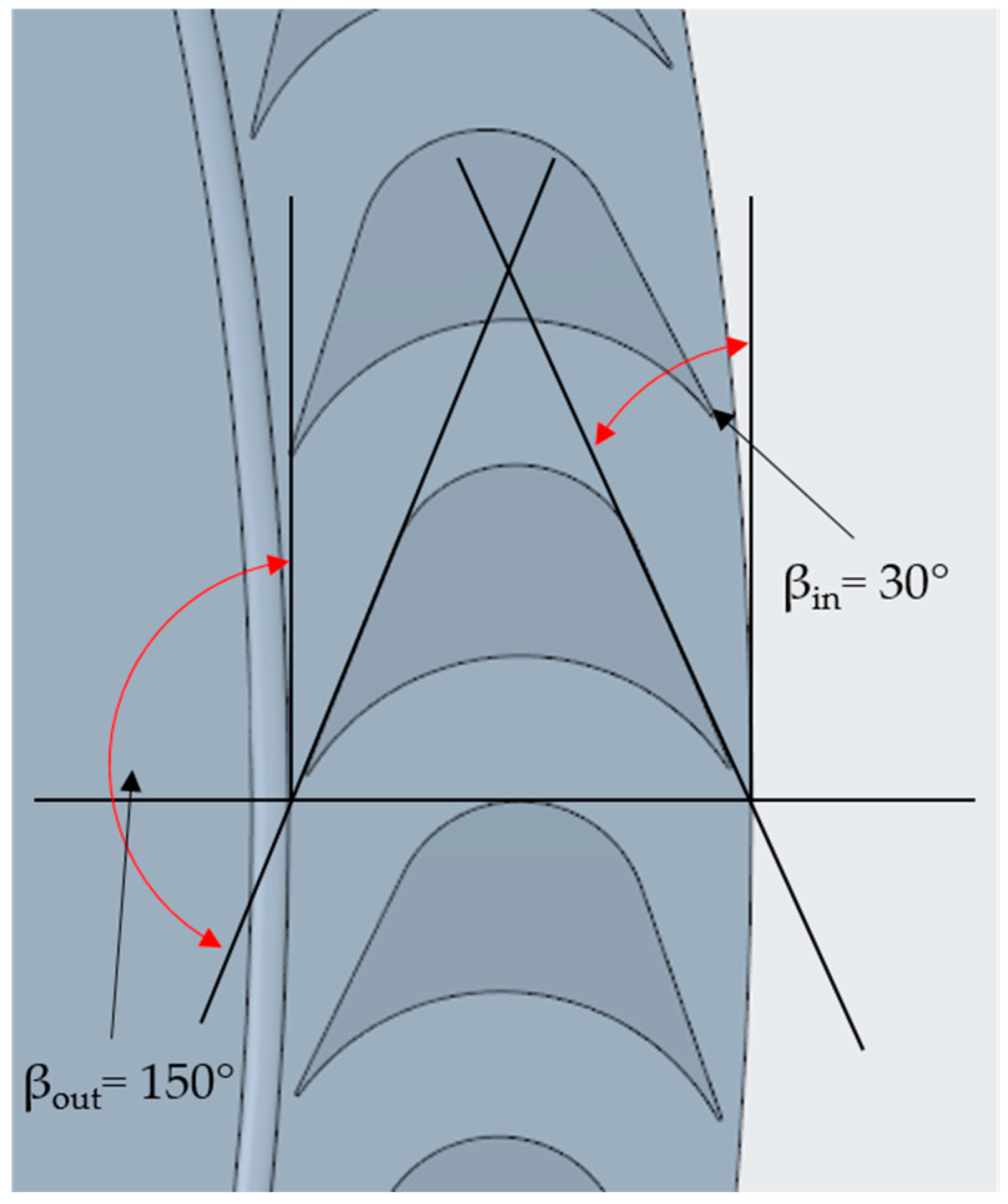
| Blade relative inlet angle | ° | 30 | 30 |
| Blade relative outlet angle | ° | 150 | 150 |
| Blade-channel width | mm | 3.5 | 3.5 |
| Blade-height outer diameter | mm | 19.7 | 17.17 |
| Blade-height inner diameter | mm | 27.6 | 19.8 |
| Nozzle throat area | mm2 | 111.24 | 111.24 |
| Nozzle outlet area | mm2 | 406.78 | 406.78 |
| Nozzle length (throat to outlet) | mm | 142.42 | 49.72 |
| Nozzle-inclination angle | ° | 26.43 | 26.43 |
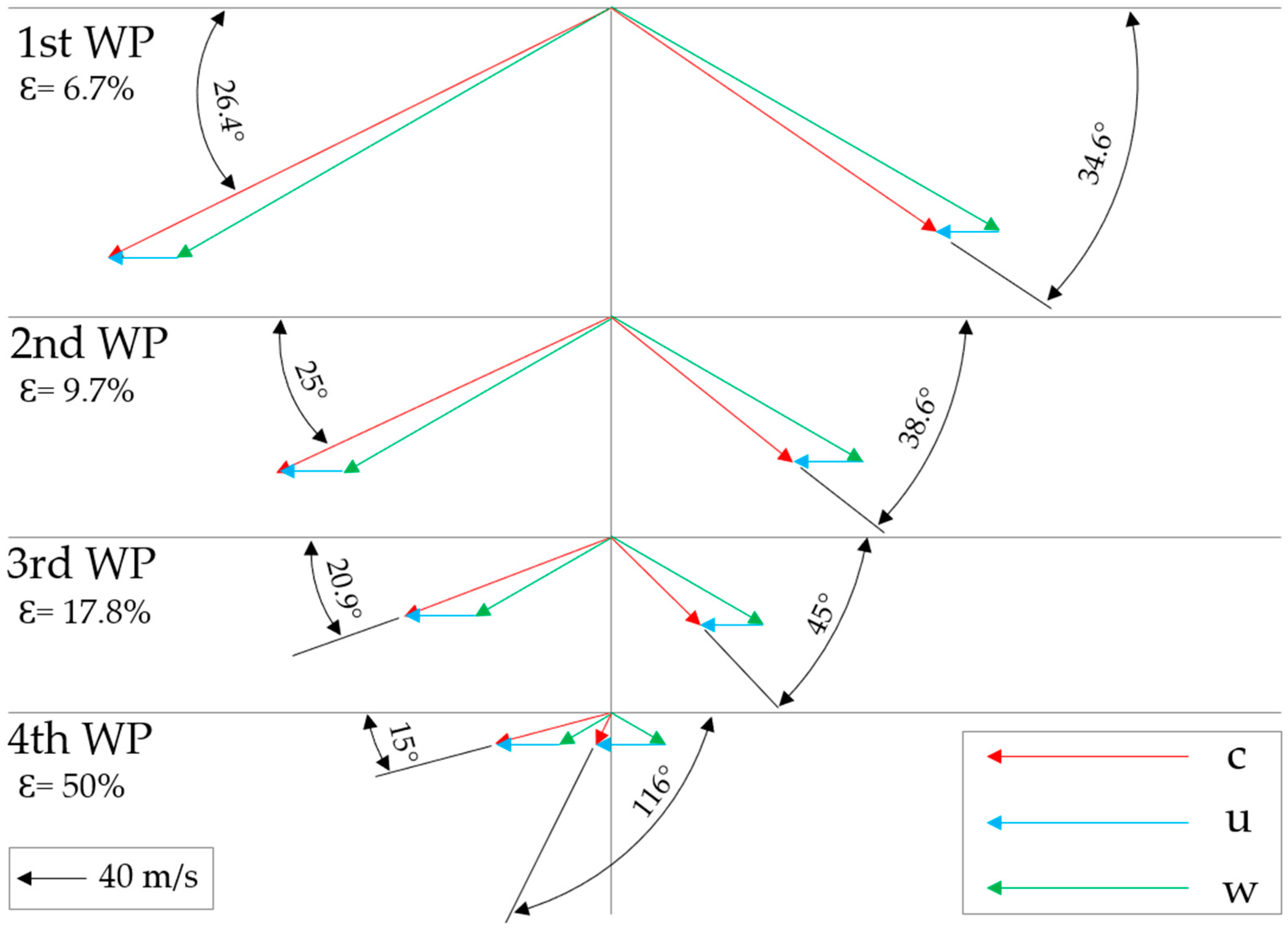
| 1st wheel-pass degree of admission | % | 6.7 | 6.7 |
| 1st deflection-channel inlet angle | ° | 145.43 | 145.43 |
| 2nd wheel-pass degree of admission | % | 9.7 | 9.7 |
| 2nd deflection-channel inlet angle | ° | 141.35 | 141.35 |
| 3rd wheel-pass degree of admission | % | 17.8 | 17.8 |
| 3rd deflection-channel inlet angle | ° | 135.51 | 135.51 |
| 4th wheel-pass degree of admission | % | 50 | 32 |
| Calculated efficiency, ηis,ts (1DTDT) | % | 39 | |
| Expected shaft power | kW | ≈6–7 |
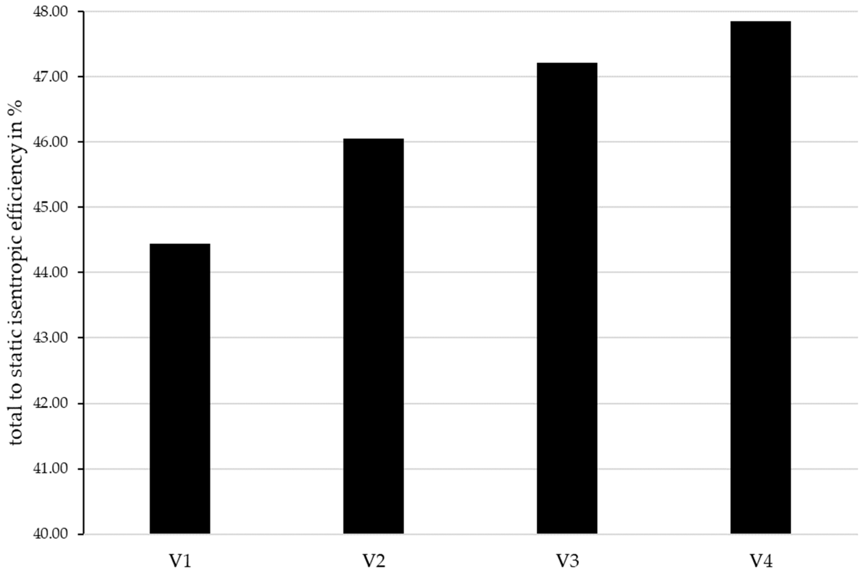
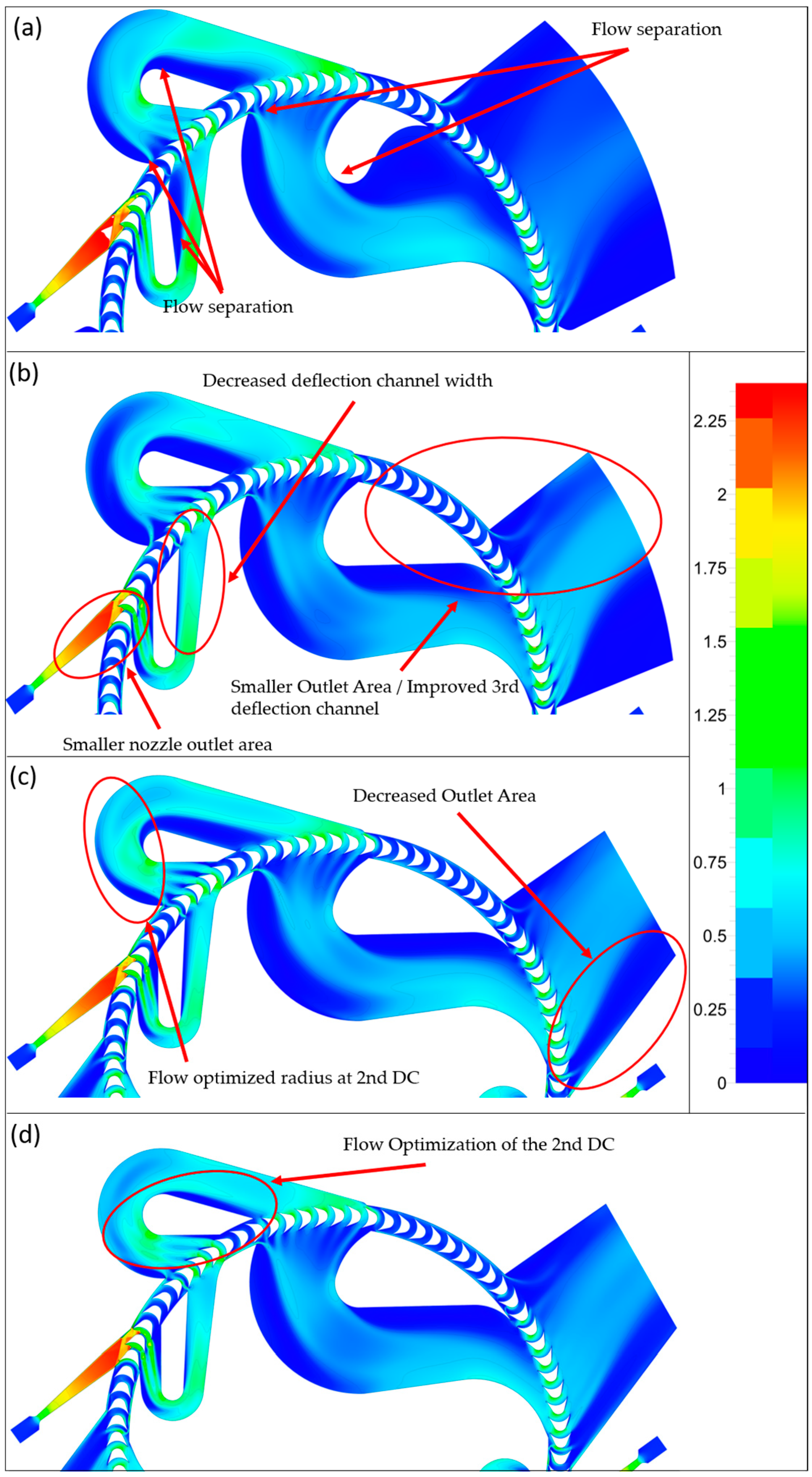
| Versions of the Turbine | Changes to the Geometry |
|---|---|
| V1 | _ |
| V2 | Smaller nozzle outlet area (406.27 mm2 to 339.6 mm2), decreased deflection channel (DC) width (20.20 mm to 15.03 mm), improved 3rd deflection channel (outlet from 16% to 8.8% admission), smaller outlet area (12.2% to 9.34% of the circumference) |
| V3 | Flow optimized radius at 2nd DC (radius from 38.23 mm to 35.16 mm), decreased outlet area (9.34% to 6.36% at the outer circumference) |
| V4 | Flow optimization of 2nd deflection channel (decreased channel width from 29.93 mm to 24.81 mm), increased inner DC height (from 18.87 mm to 20 mm) |
Disclaimer/Publisher’s Note: The statements, opinions and data contained in all publications are solely those of the individual author(s) and contributor(s) and not of MDPI and/or the editor(s). MDPI and/or the editor(s) disclaim responsibility for any injury to people or property resulting from any ideas, methods, instructions or products referred to in the content. |
© 2024 by the authors. Licensee MDPI, Basel, Switzerland. This article is an open access article distributed under the terms and conditions of the Creative Commons Attribution (CC BY) license (https://creativecommons.org/licenses/by/4.0/).
Share and Cite
Streit, P.; Weiß, A.P.; Stümpfl, D.; Špale, J.; Anderson, L.B.; Novotný, V.; Kolovratník, M. Concept and Design of a Velocity Compounded Radial Four-Fold Re-Entry Turbine for Organic Rankine Cycle (ORC) Applications. Energies 2024, 17, 1185. https://doi.org/10.3390/en17051185
Streit P, Weiß AP, Stümpfl D, Špale J, Anderson LB, Novotný V, Kolovratník M. Concept and Design of a Velocity Compounded Radial Four-Fold Re-Entry Turbine for Organic Rankine Cycle (ORC) Applications. Energies. 2024; 17(5):1185. https://doi.org/10.3390/en17051185
Chicago/Turabian StyleStreit, Philipp, Andreas P. Weiß, Dominik Stümpfl, Jan Špale, Lasse B. Anderson, Václav Novotný, and Michal Kolovratník. 2024. "Concept and Design of a Velocity Compounded Radial Four-Fold Re-Entry Turbine for Organic Rankine Cycle (ORC) Applications" Energies 17, no. 5: 1185. https://doi.org/10.3390/en17051185
APA StyleStreit, P., Weiß, A. P., Stümpfl, D., Špale, J., Anderson, L. B., Novotný, V., & Kolovratník, M. (2024). Concept and Design of a Velocity Compounded Radial Four-Fold Re-Entry Turbine for Organic Rankine Cycle (ORC) Applications. Energies, 17(5), 1185. https://doi.org/10.3390/en17051185