1. Introduction
A downhole turbine generator (DHTG) is a hydraulic turbine machine designed to operate in oil and gas wells. It converts the pressure energy of the flowing medium in the drill-string into mechanical and then electrical energy to power downhole electrical equipment. However, these generators have a relatively short lifespan and often experience malfunctions, primarily due to bearing damage. The maintenance cycle for existing DHTGs is several hundred hours, nearly thirty times shorter than that of conventional large generators. This highlights the contradiction between the lifespan of DHTGs and the demand for downhole power requirement. As the development of shallow oil and gas resources approaches its peak [
1], the further popularization of downhole drilling equipment is a prevailing trend. Therefore, research on downhole power sources holds significant academic and practical significance. Ahmad et al. [
2] highlighted the lack of long-term reliability in disposable battery power solutions and proposed a single-phase flow power harvesting system based on fluid flow. Facing the harsh conditions of high temperature and high pressure in deep oil wells, Plamp and Ben [
3] designed a turbine generator resistant to high temperature and pressure. Subsequently, they manufactured a prototype and conducted laboratory tests, although the anticipated working environment during the design phase was not tested. Guo et al. [
4] optimized the structure of traditional magnetic-coupled turbine generators, proposing a stator-sealed downhole turbine permanent magnet generator. They provided a design method for addressing electromagnetic thermal, stress field, and other physical fields. The feasibility of the method was validated through a combination of experimental data and simulation results. However, no prototype was manufactured for performance testing. Apart from the pressure energy, the produced fluid from the reservoir carries abundant thermal energy, which can be converted to electric power with thermoelectric technology. Liu et al. [
5] designed a thermoelectric generator to convert the thermal energy from reservoir production fluid into electricity. Numerical simulations showed that the generated output power could meet the requirements of typical downhole applications.
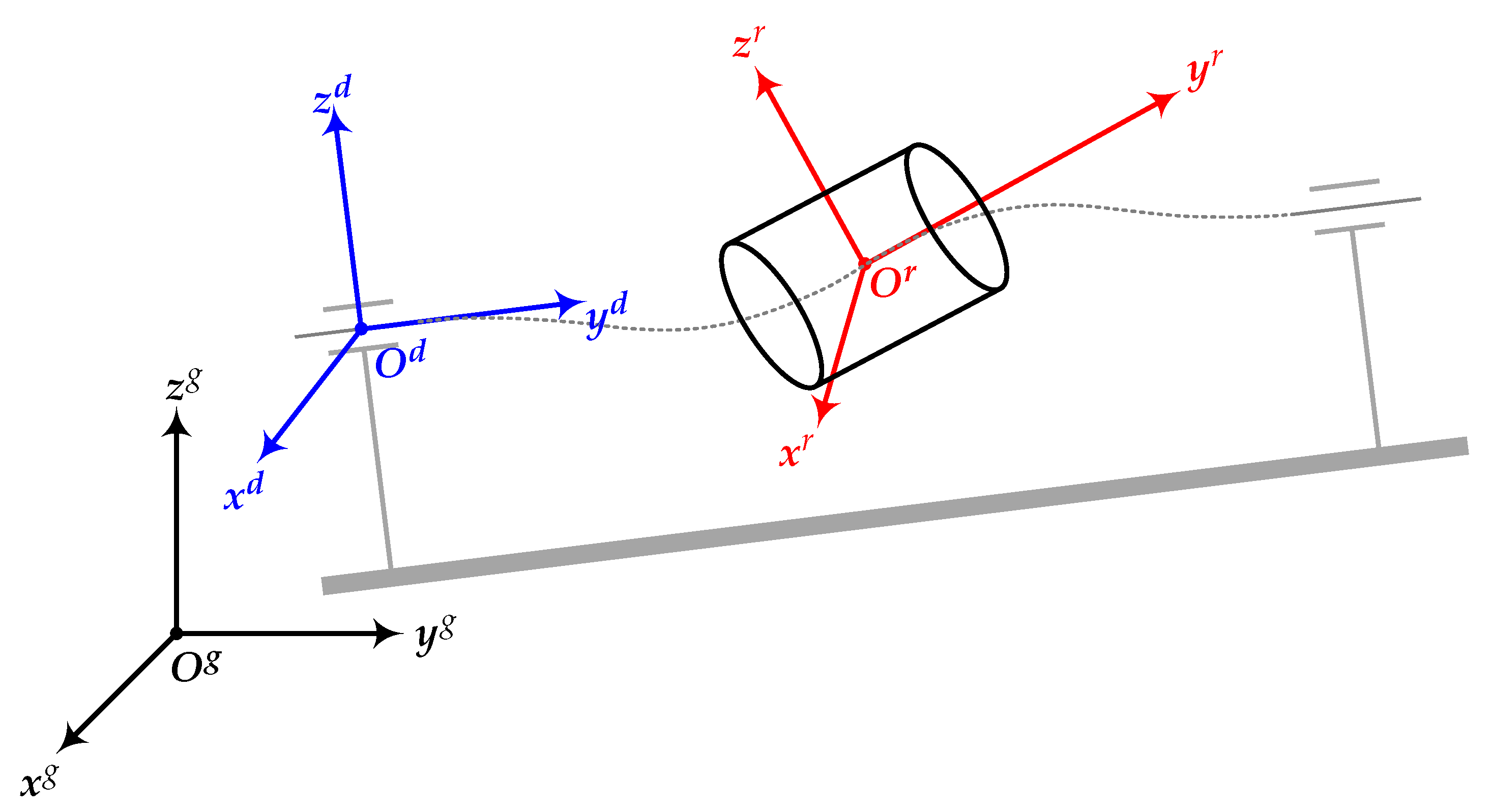
The outer diameter of the DHTG’s casing is constrained by the external dimensions of the tool, requiring the rotor structure to be designed as a slender rod, as shown in
Figure 1. The rotor-bearing system(RBS) of the DHTG is subjected to complex internal and external excitation, including hydraulic and electromagnetic excitation. Simultaneously, manufacturing defects in rotating components, material irregularities, and the challenging working environment of the generator contribute to an inevitable mass unbalance along the rotor. Under the influence of complex internal and external excitation, the bearings experience additional dynamic loads. The generator’s lifespan is deeply rooted in these loads. Therefore, a detailed analysis of the dynamic characteristics of the rotor system under drill-string excitation must be conducted to increase the generator’s lifespan and prevent catastrophic failures during operation.
The dynamic analysis of rotor requires the deformation description of rotor shaft deformation. The typical description methods include Euler–Bernoulli beam theory and Timoshenko beam theory, with the latter considering the shear effects of the beam. Zhang and Gao [
6] established a non-classical Euler–Bernoulli beam model considering coupling stress and strain gradient effects; they solved the bending and vibration of simply supported beams and found that the beam deflection was smaller and the natural frequency was higher compared to the classical model. Alavi et al. [
7] developed a linear size-dependent Timoshenko beam model based on the consistent couple stress theory. They computed general deformation, mass, and stiffness matrices, among others. In comparison with the traditional Timoshenko beam model, the new model exhibits lower dependence on the constituent material of the beam within its validity domain. Ahmadi [
8] utilized the Timoshenko beam theory to derive the governing equations for beams in multiple-nanobeam coupling systems. He investigated the free vibration of the system under different edge boundary conditions and verified the accuracy of the equations by comparing the results with those from existing literature. Xie et al. [
9] derived a first-order shear deformation beam theory for flexural vibration. By comparing the free vibration results with Timoshenko’s beam theory, they found that the established theory has higher solution accuracy. The establishment of the finite element model motion equations for the rotating shaft requires solving the shape functions of the rotor. Chen and Ku [
10] derived the shape functions for Timoshenko beam theory and applied them to analyze the dynamic stability behavior of the shaft-disc system under axial forces.
The proposition of base excitation on RBS first appeared in the vibration research of large turbines under seismic loads and later evolved into a branch of rotor dynamics. The drill-string is rigidly connected to the support of rotor, and the motion of the drill-string is essentially the motion of the support. The motion of the drill-string can be considered the combined effect of one or more base excitations. Lee et al. [
11] proposed a finite element model for a flexible rotor system under the transmission of impact excitations from the support. They provided numerical and experimental analyses of the transient response of the model. Kumar and Tiwari [
12] developed an identification algorithm for the unbalanced rotor model supported by active magnetic bearings. They utilized FFT to estimate the eccentricity and constant force of the bearing based on response harmonics. The effectiveness of the algorithm was validated at different speeds. Dakel et al. [
13] introduced the on-board rotor model based on Timoshenko beam theory, analyzing the dynamic responses of symmetric and asymmetric rotor models under rotational and translational excitations of the rotor base by means of stability charts and orbits of the rotor. Sousa et al. [
14] conducted an analysis in both the time and frequency domains for the mathematical model of the rotor containing a horizontal flexible shaft, two rigid discs, and two self-aligning ball bearings. They studied the differences between regular rotors and on-board rotors under various base excitations. Chen [
15], while analyzing the impact of base rotation on a rotor model, designed a novel test rig capable of simulating base angular movement to validate the proposed model. Briend et al. [
16] established a six-degrees-of-freedom rotor model mounted on hydrodynamic finite-length bearings, studying the static equilibrium point stability problem under multi-frequency parameter excitations generated by supporting motion using Floquet theory. Gao et al. [
17] developed a flexible asymmetric aero-engine rotor system, studying the nonlinear dynamic behavior during maneuvering flights under different forms of excitations, including acceleration translation, acceleration rotation, and a combination of both.
In order to eliminate the influence of various forms of excitation on rotor operation, it is necessary to take certain measures to reduce vibration. Currently, there are limited methods for vibration control of DHTG’s RBS. The main approach is to use magnetic couplers to isolate external excitations, which has some effect in blocking hydraulic excitations on the turbine but is limited in its effectiveness against drill-string excitations. Squeeze film dampers (SFD) can effectively reduce the vibration of rotating mechanical RBS caused by drill-string excitations. They have shown good application results in various fields such as aviation engines, ships, and gas turbines. In the context of vibration control in DHTG’s RBS using SFD, there is significant potential for application.There have been numerous studies on the vibration behavior of RBS under SFD control. Ma et al. [
18] combined the finite element method with the free interface modal synthesis method to establish a dual-rotor system supported by rolling bearings equipped with SFD. They analyzed and compared the effects of SFD imbalance and oil film clearance on the steady-state response of the system. The results indicated that SFD could effectively suppress amplitude jumps of the system. Ri et al. [
19] computed the nonlinear forces of SFD oil films and analyzed the dynamic response of the Jeffcott rotor system supported by SFD using the incremental harmonic balance method. The results were compared with numerical integration, showing close agreement. Frequency response curves were also provided for variations in parameters such as gravity and unbalance. As theoretical research has advanced, various new types of dampers have emerged. Heidari and Safarpour [
20] proposed an active squeeze film damper (ASFD), combining the excellent load-carrying capacity of the squeeze film damper with the controllable characteristics of magnetic bearings. They studied the influence of rotor system characteristic parameters on the unbalance response and transfer force. Han et al. [
21] proposed an elastic ring squeeze film damper(ERSFD) and provided numerical simulations of the rotor system’s dynamic equations. By suppressing the nonlinear effects of the oil film, they achieved the mitigation of rotor bi-stable jumping.Furthermore, the dynamic characteristics of the damper-rotor system under base excitation have attracted attention. Yan et al. [
22] designed a single-disc rotor test rig with mass unbalance and base excitation, testing the damping effect of integral squeeze film damper(ISFD) on sinusoidal base excitations of different frequencies. In terms of numerical simulation, Chen et al. [
23] established a finite element model of a rotor-bearing system supported by a squeeze-film damper with a retainer spring and discussed the nonlinear response and bifurcation of the system under base rotational and translational excitations. In damper modeling, Gheller et al. [
24] established a squeeze film damper model considering oil film cavitation, air ingestion, and inertia based on the two-dimensional Reynolds equation. They validated the model with experimental results and provided directions for further optimization and improvement.
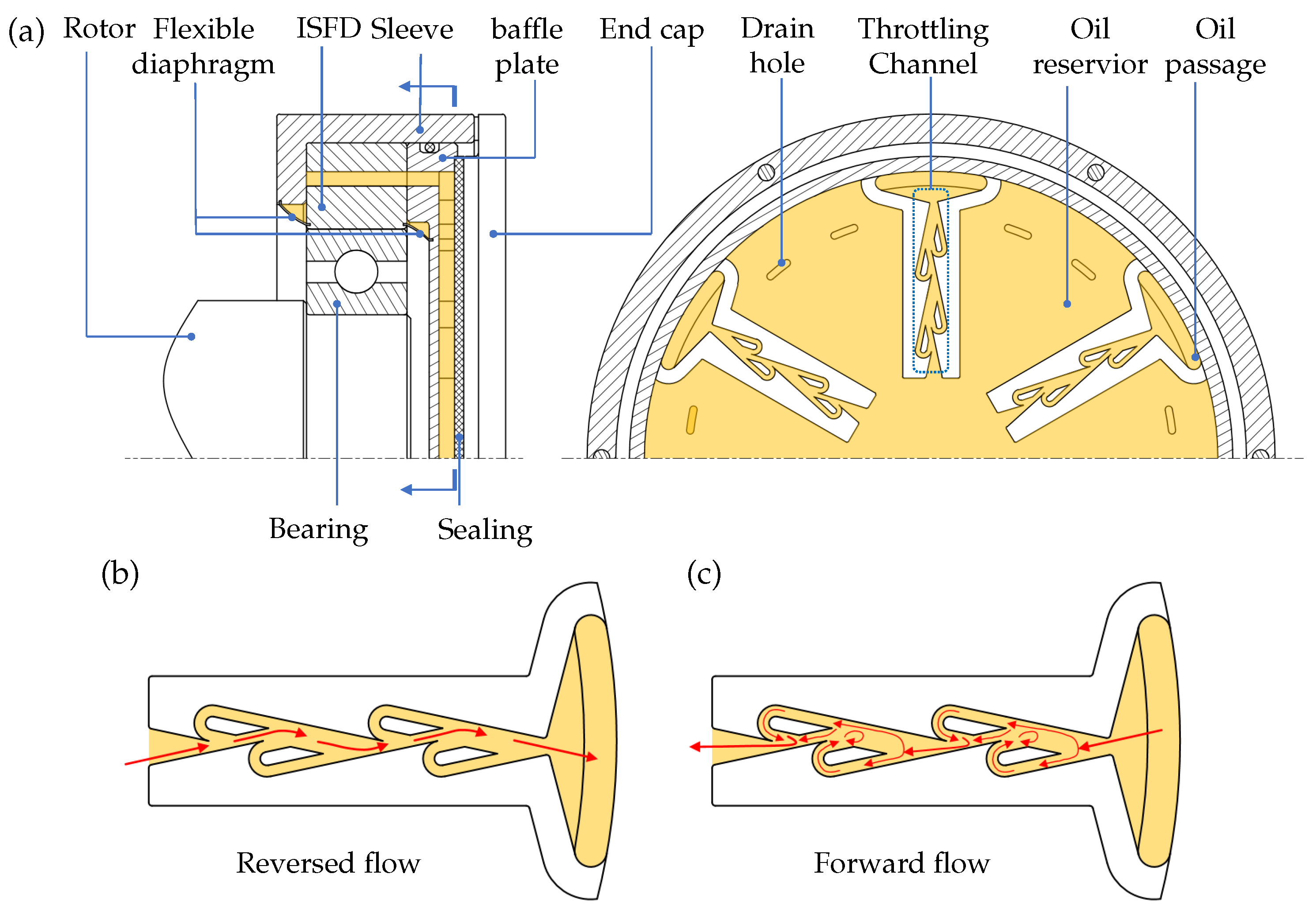
We propose a novel SFD for vibration control, which effectively reduces the bearing forces on the shaft. This paper employs numerical methods to study the vibration behavior of the generator’s RBS under drill-string excitation and the vibration behavior of the RBS after introducing SFD. The approach to studying the kinematics and dynamics characteristics of the DHTG during the drilling process in this paper is:
The relative positional relationships between the rotor, drill-string, and the ground are expressed using Euler angles in a fixed reference frame. To facilitate the description and solution of motion quantities, the translational motion of the rotor is described in the drill-string reference frame, while the rotational motion of the rotor is described in the rotor reference frame.
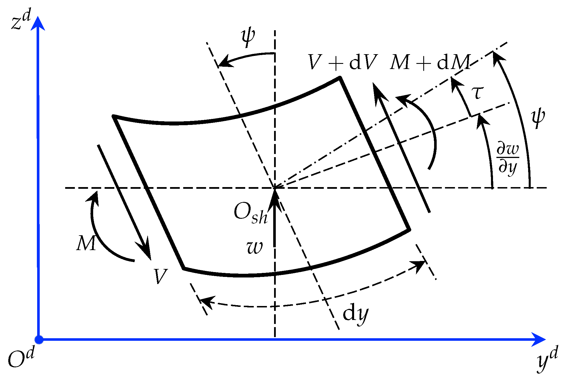
Based on the geometric features of the rotor, discrete elements are used to model the continuous shaft using Timoshenko beam elements. Mass unbalance is discretized using lumped mass, and a linearized bearing model is established. The operating principle, structure, and discrete model of the squeeze film damper are provided.
The Lagrangian dynamics equations for the discrete system are established, and numerical integration is employed to solve the dynamic equations of the rotor-bearing system in the time domain.
Analyze the dynamic response of the rotor during constant speed operation in the the time-domain waveforms, whirl orbit, and FFT spectrum. Investigate the impact of different drill-string excitations and various parameters of the same excitation type on the displacement response. Validate the damping performance of the damper during rotor operation near the critical speed and examine the influence of different excitation forms on the displacement response and bearing load during operation near the critical speed.
3. Results and Discussion
On the basis of
Figure 7, a rotor bearing system model with the number of nodes
j = 13 and
i = 5 is established. The material of the rotor shaft is carbon steel, and the specific parameters of shaft are shown in
Table 1. The lengths of the shaft elements are given by
. The cross-sectional areas of the shaft elements are
, and
. Bearing 1 is at node 5 and bearing 2 is at node 13. The specific parameters of bearings and SFD are shown in
Table 2.
3.1. Constant Speed Operation Process
This subsection discusses the impact of different drill-string excitation forms on the dynamic responses of the RBS during constant speed operation. The main forms of excitation generated during the drilling process of the drill-string include lateral translation, lateral oscillation, axial rotation, and lateral pulse. The MU at node 9 is g·cm, and the phase is . The rotor operates at a speed of . The Newmark-fi integration method is used to calculate the dynamic responses of the system, with 1000 periods calculated, and the last 25 periods are taken to plot time waveform, whirl orbit, and FFT spectrum of node 9, analyzing the rotor’s dynamic response.
3.1.1. Drill-String Fixed and Lateral Translation
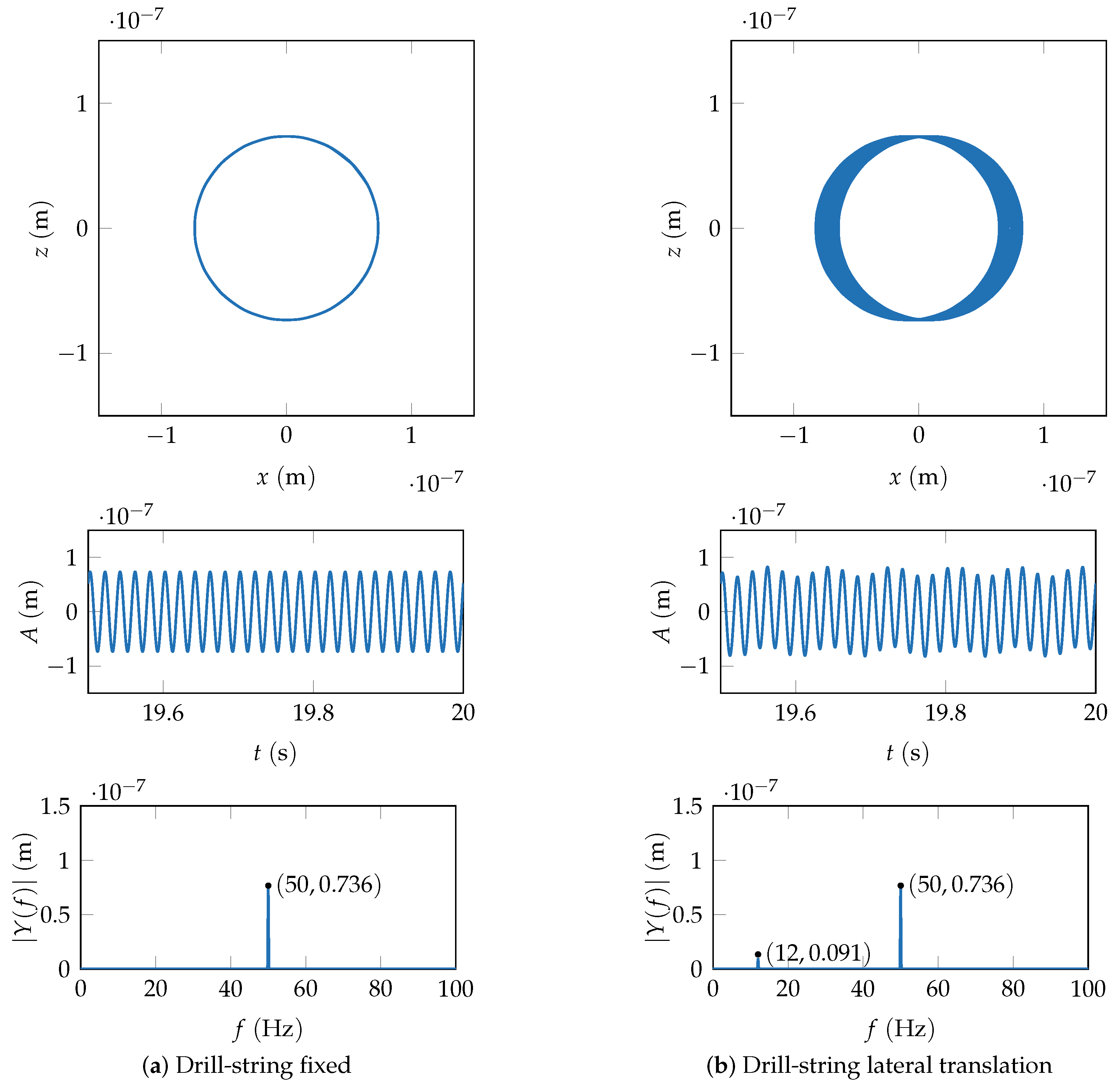
Figure 8a shows the case where the drill-string is fixed. The amplitude and period of time waveform in
x and
z directions are the same, with different initial phases, and the lateral responses maintain isotropy. The corresponding whirl orbit is a circular path, indicating synchronous periodic motion. The FFT spectrum only shows the rotational frequency
.
Figure 8b depicts the case of the drill-string under
x-direction translation, with the excitation form
, where the amplitude
is
and translational frequency
is
. The whirl orbit shows a circular shape spreading in
x direction, and the whirl orbit remains symmetric in
x and
z directions. The FFT spectrum exhibits the translational frequency component
, but the spin frequency component
predominates.
By using the control variable method, keeping
constant at
, and varying
, the changes of whirl orbit are analyzed. Let
represent the proportional relationship between the drill-string’s translational frequency and the rotor’s spin frequency.
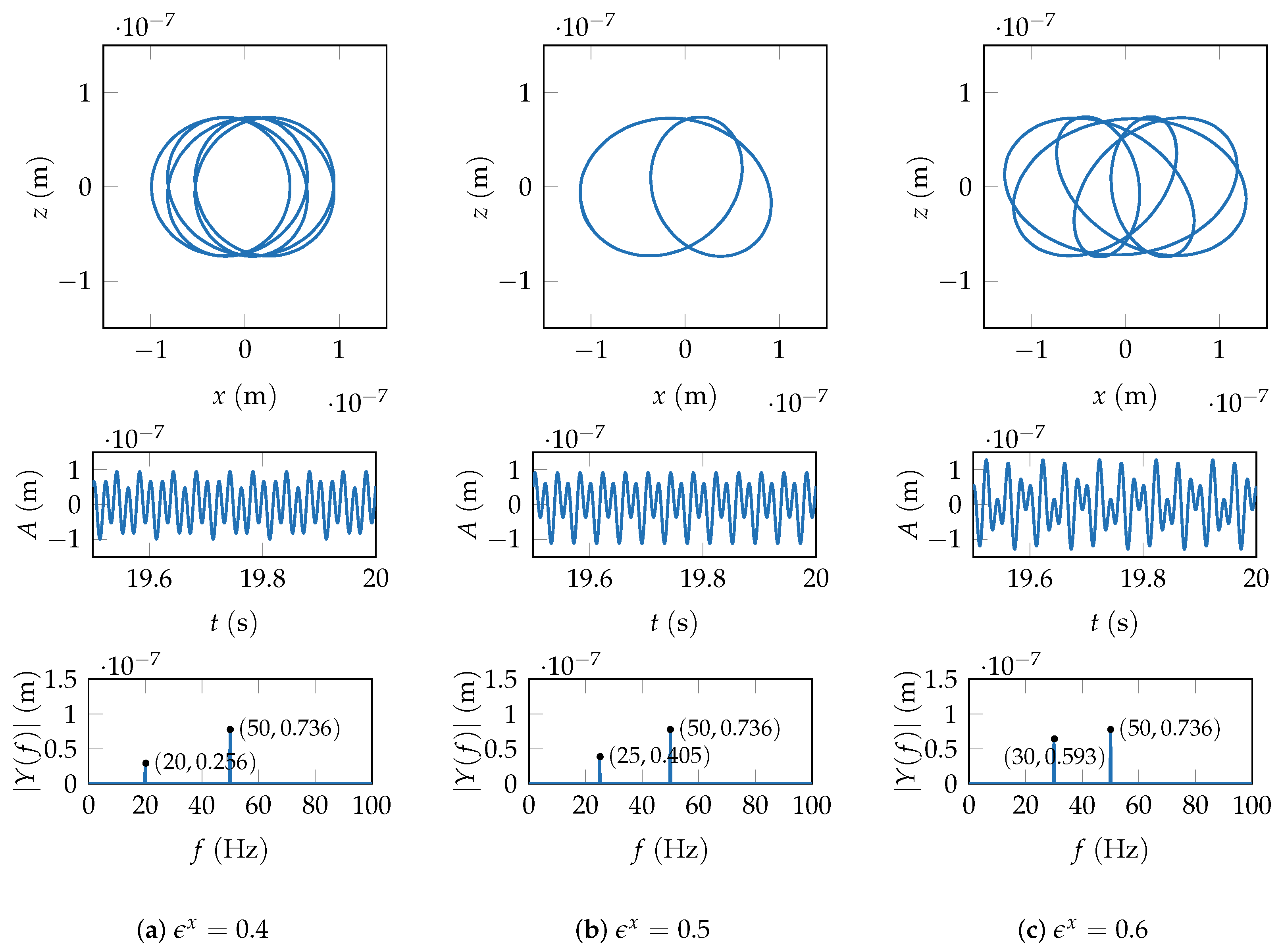
Figure 9 shows the displacement responses under different translational frequency of the drill-string.
When
, as shown in
Figure 9a, the shape of the whirl orbit is formed by overlapping circular translations in
x direction (direction of excitation), with an increased translation amplitude compared to
. When
, the whirl orbit becomes quite special. At this point, the spin frequency of the rotor is an integer multiple of the drill-string’s translational frequency. As shown in
Figure 9b, the whirl orbit is no longer circular, and it resembles two partially overlapping ellipses. When
increases to 0.6, the corresponding whirl orbit transforms into a complex shape, as shown in
Figure 9c, resembling several ellipses with
z direction as the axis of symmetry, rotating at different angles in the
plane. The
x-direction displacement response is highly sensitive to changes in the translational frequency of the drill-string, while the corresponding
z-direction displacement response is almost unaffected. The shape of the whirl orbit undergoes significant changes, while the range of the whirl orbit (especially in the
z direction) does not change significantly. In all three cases, the whirl orbit does not strictly maintain symmetry in the
z direction, which is due to the initial phase caused by the presence of MU. As
increases from 0.4 to 0.6, the higher drill-string translational frequency exacerbates the asymmetry phenomenon. During this process, the frequency component of the drill-string’s excitation in the FFT spectrum gradually increases.
3.1.2. Drill-String Lateral Oscillation
Changing the excitation form to lateral oscillation, the oscillation amplitude is around the
z direction
, where
is the maximum oscillation amplitude, and
is the oscillation frequency. Similar to the lateral translation study, using the control variable method, keep
constant at
and change
. Analyze the change of the whirl orbit. Let
represent the proportional relationship between the lateral oscillation frequency of the drill-string and the rotor’s spin frequency.
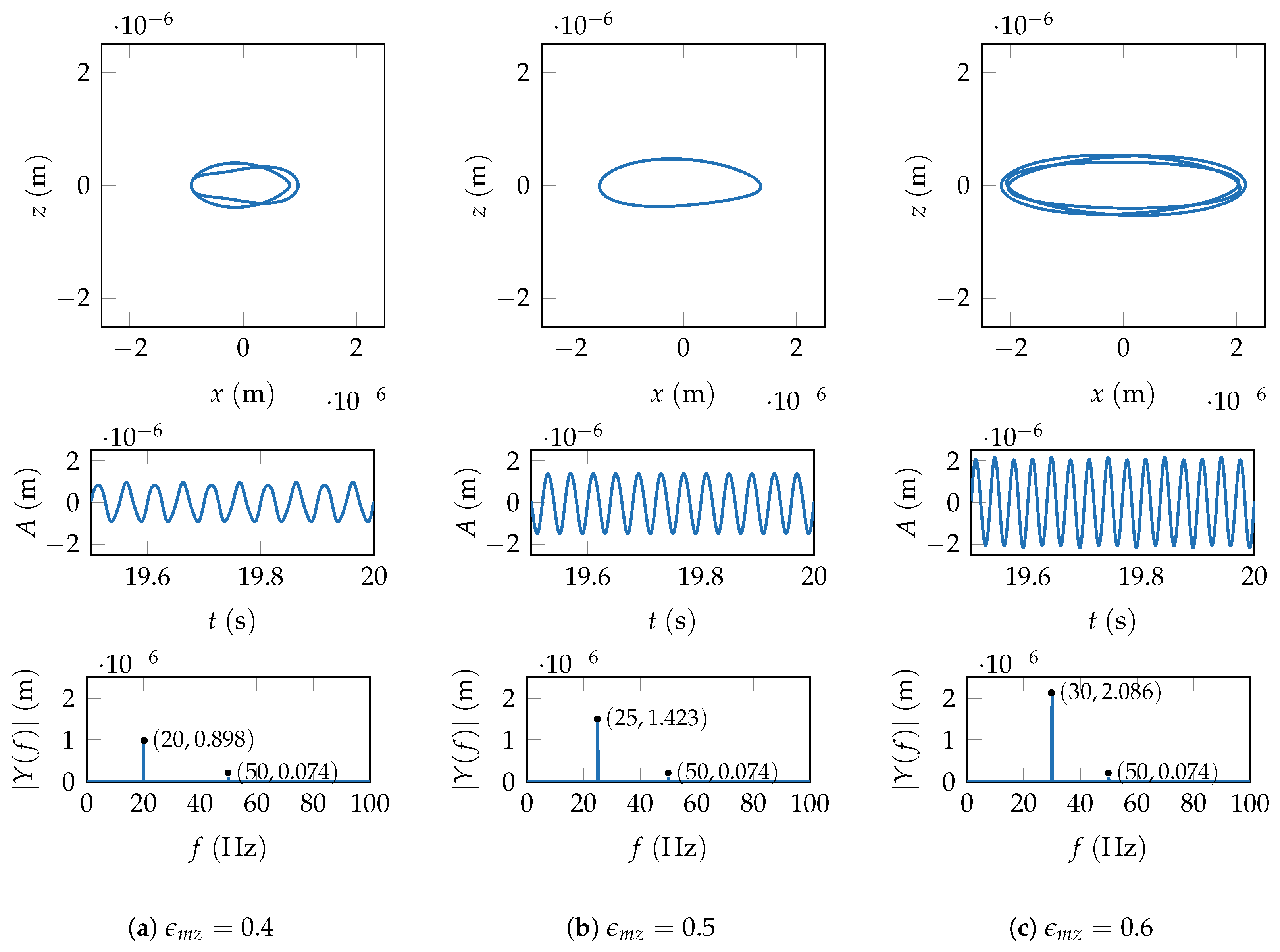
Figure 10 shows the displacement responses under the excitation of lateral oscillation of the drill string.
When
, as shown in
Figure 10a, the whirl orbit appears as an incomplete overlap of two elliptical shapes. Particularly, when
, the rotor’s rotational frequency is an integer multiple of the excitation frequency, as shown in
Figure 10b; at this point, the whirl orbit approximates an ellipse. As
continues to increase to 0.6, the orbit becomes complex again, as shown in
Figure 10c, resembling the superposition of multiple elliptical shapes.
By comparing the whirl orbit and the time waveform, it can be observed that, unlike the lateral translational frequency, the variation in lateral oscillation frequency not only affects the shape of the whirl orbit but also significantly alters the amplitude of the displacement response in the oscillation direction. Even though the oscillation frequency is lower than the rotor’s rotational frequency, its contribution in the FFT spectrum is much larger than that of the rotor’s rotational frequency and increases further with the excitation frequency.
3.1.3. Drill-String Axial Rotation
When changing the drill-string excitation to axial rotation, with the axial rotation frequency denoted as
, as shown in
Figure 11a,b, axial rotation excitation does not change the shape of the whirl orbit, which still remains circular, and the displacement response maintains isotropy. Since the rotor’s spin frequency is
, and it does not approach the critical frequency of
, when
is
and
, the whirl orbit increases and decreases, respectively.
Figure 11c represents the case when the spin frequency is
, and no excitation is applied. The whirl orbit is almost identical to
Figure 11b.
Unlike lateral translation and lateral oscillation excitations, the frequency of the drill-string’s axial rotation does not appear in the FFT spectrum. However, it affects the amplitude of the rotor’s spin frequency in the spectrum. In terms of the effect, it is like the superposition of the spin frequency and the excitation frequency. When the excitation is , its effect is very similar to that of the spin frequency . Although the frequencies are different in the spectrum, the amplitudes are approximately equal.
3.1.4. Drill-String Lateral Impulse
When changing the excitation form to lateral impulse, in this excitation form, we focus more on the differences in the time waveform between the
x and
z directions rather than whirl orbit. The pulse form is a half-cycle sine wave and can be expressed as:
where
is the impulse magnitude, and
is the impulse duration. The impulse acts in the
x direction. Keep
constant at 10 mm, and change
.
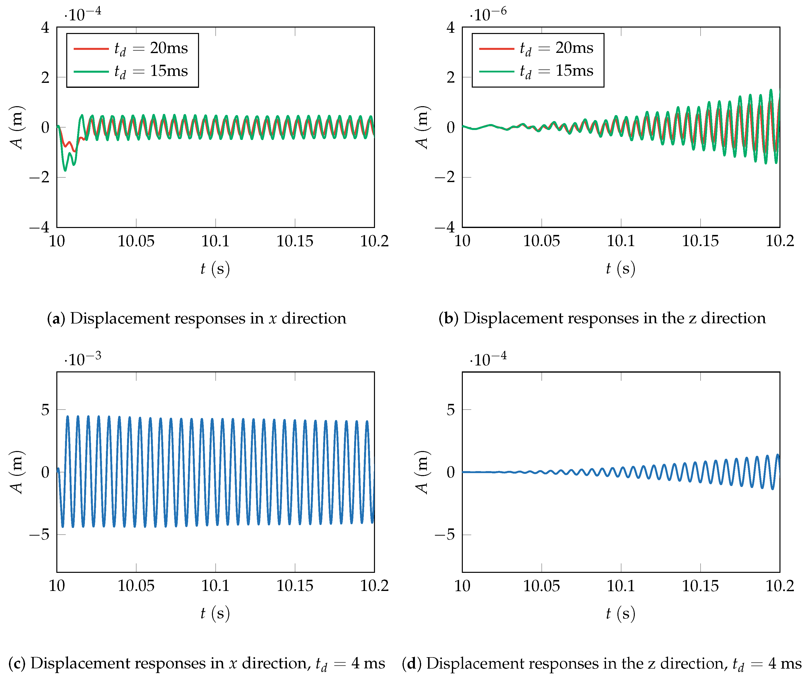
After operating at a constant rotor speed for
, impulse excitation with a duration of
and
was applied separately. The displacement responses are shown in
Figure 12a. Within the impulse duration, the displacement response in the
x direction is significantly influenced, exhibiting an increased amplitude. Moreover, as the impulse duration
decreases, the amplitude change becomes more pronounced. This is attributed to the fact that with a shorter
, the energy density per unit time is higher, leading to more intense vibrations in the system. For longer impulses, the excitation’s frequency distribution is broader, preventing the system from having sufficient time to establish resonance. Consequently, the vibration response of the system rapidly diminishes after the impulse concludes. The influence of
on the response after the impulse disappearance is limited. Although the impulse is applied in the
x direction, and the cross stiffness of the bearings is neglected, due to the gyroscopic effect, the system exhibits impact responses not only in the vertical direction but also generates gradually increasing displacement responses in the horizontal direction over time, as depicted in
Figure 12b.
Further reducing
to
, the impulse duration becomes less than the system’s natural vibration period. The vibration response is depicted in
Figure 12c,d. The displacement response in the
x direction does not immediately decay after the impulse disappears; instead, it gradually decreases over time. Simultaneously, both the
x and
z-direction displacement responses exhibit a significant increase in amplitude. This phenomenon arises from the short impulse duration causing the excitation to be distributed in a narrower frequency range, concentrating more on frequencies that match the system’s natural frequency. The resonance effect intensifies, allowing the system to absorb sufficient energy, resulting in sustained vibrations after the impulse concludes. This implies that, to enhance the rotor system’s resistance to impulse excitation, it is advisable to increase the system’s natural vibration period. Moreover, it is crucial to ensure that the pulse excitation duration during operational conditions exceeds the system’s natural vibration period.
3.2. Acceleration Process
The displacement response is observed at node 9, where the MU is applied, and the bearing load is observed at node 13, where the damper is installed. Initially, the dynamic behavior of the rotor during the acceleration and the influence of the SFD on the rotor’s dynamic response are investigated. The at node 9 is set to g·cm with a phase angle of .
When the drill-string is fixed to the well bore, as shown in
Figure 13a, the critical speed of the system remains 1000 rad·s
−1. SFD effectively increases the damping of the system, the peak amplitude of lateral vibration at the critical speed is reduced, and the amplitude decreases more rapidly after the critical speed, allowing the rotor to pass through the critical speed safely. Regarding the damping effect of the SFD, the simulated damping percentages reach 58.21%. Another role of the damper, namely, reducing the bearing load, is also taken into account. The results are shown in
Figure 13b, where the bearing load at node 13 is reduced by 54.95% after SFD operation.
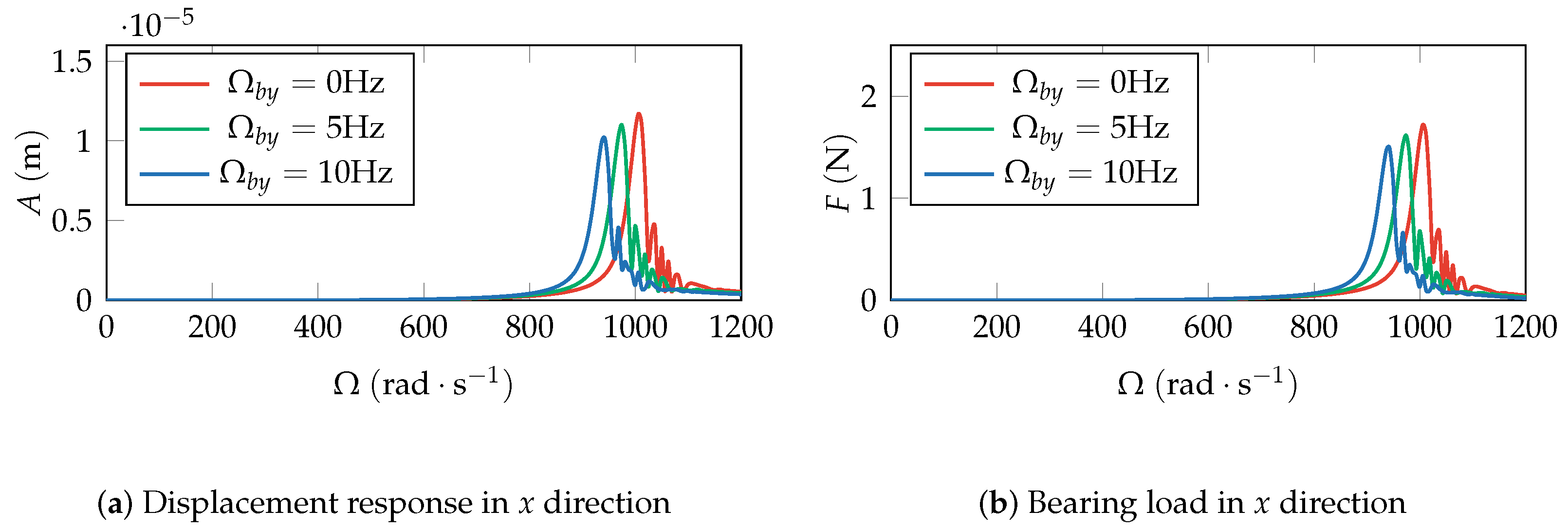
Taking the results of the fixed drill-string as reference, changing the form of the drill-string excitation, the displacement response, and bearing load variation of the system with SFD installation is studied. Considering the drill-string rotates axially, the rotational direction of drill-string is identical to that of the rotor shaft. The displacement response at node 9 and the bearing load at node 13 are analyzed for the
x direction only, as it does not change the lateral isotropy of the shaft. When the axial rotation angular velocity
of the drill-string increases from
to
, the displacement response and bearing load are shown in
Figure 14. Compared with the drill-string fixed case, the critical speed of the system slightly decreases, as the angular velocity
increases, and the peak value of the displacement response correspondingly decreases. At the same time, the peak value of the corresponding bearing load also decreases, maintaining a consistent trend with the change in the peak value of the displacement response.
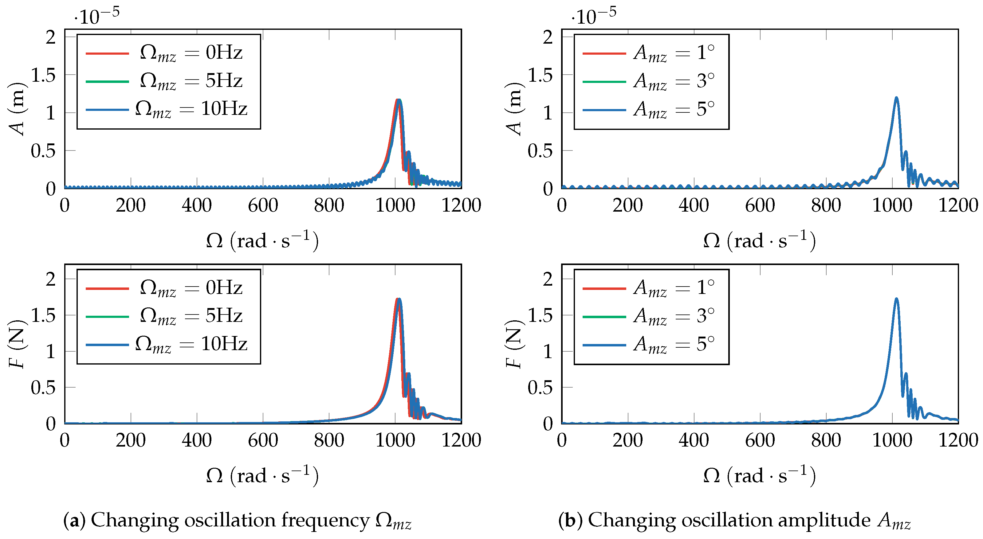
The most common form of drill-string excitation caused by external disturbances in oil and gas wells is lateral oscillation. Applying lateral oscillation around the
z-axis, the lateral oscillation frequency
varies from
to
, and the amplitude of lateral oscillation
varies from
to
. The
x-direction vibration amplitude at node 9 and the
x-direction load at rear bearing are shown in
Figure 15. Compared to the results of drill-string fixed, lateral oscillation increases the amplitude of the entire acceleration process displacement response. This phenomenon is gradually obvious with the increase of the oscillation frequency and oscillation amplitude. In the low-speed region, a more obvious displacement response with sinusoidal oscillation can be observed under lateral oscillation excitation. In contrast to axial rotation excitation, lateral oscillation excitation has no significant impact on the critical speed or the displacement response near the critical speed, regardless of the frequency or amplitude of oscillation. Similarly, the simulation results for the bearing load at node 13 are provided, and the impact of lateral oscillation excitation on the bearing load is limited in both the low-speed and critical speed regions.
Through the above analysis, it can be observed that the proposed SFD effectively reduces the vibration amplitude and bearing load near the critical speed of the RBS. Based on this, when axial rotation is applied to the drill-string, the critical speed decreases with excitation frequency. Therefore, when setting the rotor speed, priority should be given to considering the frequency of axial rotation to ensure that the critical speed is far higher than the rotor speed. The lateral oscillation mainly affects the vibration amplitude in the low-speed region, and its influence on the vibration amplitude near the critical speed is minimal, regardless of the oscillation frequency or amplitude.
4. Conclusions
This paper establishes a finite element model of DHTG’s rotor-bearing system to evaluate the dynamic response of the DHTG shaft system under the time-varying drill-string motion excitation with roller bearing and rigid support. In addition to applying the Timoshenko beam theory and considering gyroscopic torque, MU, linear bearings, and the motion of the rotor determined by six degrees of freedom (lateral and axial translation, and rotation caused by bending and torsion), an inertial reference system and two non-inertial reference systems are simultaneously introduced. The shape functions of the three-dimensional six-degrees-of-freedom Timoshenko beam element are established, using cubic polynomial interpolation for lateral motion and linear interpolation for axial motion. According to the generator operating conditions, the dynamic response of the unbalanced rotor-bearing system under different time-varying drill-string excitations (axial rotation, lateral swing, lateral harmonic translation, and lateral pulse) are discussed, and the damping performance of SFD is also tested.
The main research conclusions are as follows:
The vibration control equation of the generator rotor-bearing system shows that the motion parameters’ influence is not only generated by the drill-string’s rotational motion but also by the translational motion of the drill-string when the rotor has MU.
When the rotor runs at a constant speed, the lateral sinusoidal translation of the drill-string changes the trajectory of the rotor axis motion from periodic to quasi-periodic. With the increase in the translational frequency of the drill-string, the proportion of the lateral sinusoidal translation frequency in the spectrum gradually increases. The MU causes an asymmetry in the axis trajectory in the translational direction, most evident at a frequency ratio of . Similarly, the lateral swing of the drill-string changes the trajectory of the rotor axis motion from periodic to quasi-periodic, but the proportion of the swing frequency in the spectrum is always greater than the rotor’s spin frequency, and this phenomenon is further magnified with the increase in the swing frequency. The axial rotation of the drill-string has the same effect as the simple superposition of two frequencies on the transient response.
In addition, when the drill-string has sinusoidal motion, the excitation caused by MU combines with the drill-string’s motion have not only a frequency equal to the rotor speed but also a frequency corresponding to the drill-string excitation, as well as combinations of these two frequencies.
The impulse excitation greatly increases the displacement response in the vertical direction, the response period is close to the natural vibration period of the system, and the gyroscopic effect also causes the displacement response in the horizontal direction. The shorter the pulse duration is, the stronger the response. When is less than the natural vibration period of the system, the vertical response no longer decays rapidly, with the pulse disappearing.
SFD can not only reduce the displacement response amplitude of the system near the critical speed but also significantly decrease the force at the bearing end, effectively improving the operational stability of the rotor near the critical speed.
When the rotor is running at increased speed, and the axial rotation direction of the drill-string is the same as the rotor’s rotation direction, increasing the angular velocity of the drill-string reduces the first critical speed, and the resonant amplitude also slightly decreases. When the drill-string swings laterally, whether increasing the swing frequency or the swing amplitude, the critical speed and the resonant amplitude remain basically unchanged, and the trend of the bearing force and the resonant amplitude change is consistent.
The SFD proposed in this paper not only has application value in the rotor-bearing system of DHTG but also has wide application potential in the field of vibration damping of small precision rotating machinery, including UAVs, medical equipment, and so on. However, the research work in this paper is still at the theoretical level. In the future work, the feasibility of SFD and the actual vibration damping performance of rotor-bearing systems will be experimentally studied, the finite element model established in this paper will be compared and verified, and we plan to integrate artificial intelligence for rotor system fault detection and diagnosis.

