1. Introduction
The use of sCO2 cycles to produce electric power is an emerging technology which is expected to bring substantial efficiency gains. This power generation route then attracts the interest of the power community, including producers and major OEMs as it would also reduce the size of cycle components and thus decrease the CAPEX of power plants.
However, during successive development attempts, initially carried out on small test loops, the experimenters faced technical issues which prevented the rapid release of viable pilot units. These difficulties, not anticipated by the precursors of the technology, are linked to marked specificities of sCO
2 cycles, in particular their high pressures but low-pressure ratios, the difficulty of controlling CO
2 leaks and the unusually small dimensions of certain components, which require unconventional designs. That technology is therefore still in the engineering and testing phase, with the most consistent and active program being currently the so-called “Supercritical Transformational Electric Power” (STEP), funded by the US Department of Energy (DOE) [
1,
2].
While questions legitimately arise about the reasons for this industrialization delay, this discussion is still little reflected in the academic literature.
The primary objective of this study was to tentatively fill this gap by investigating the main technical specificities and potential design obstacles which cause this long industrialization process. However, attempting to clarify such a complex and far-reaching topic required an in-depth approach to sCO2 cycles in order to understand how the specificities of these cycles impact the engineering of large power systems.
This led us to adopt the following paper plan: after a brief history and some basic definitions (
Section 2 and
Section 3), we will identify the specificities of sCO
2 cycles and deduce the associated advantages and drawbacks (
Section 4). We will then review their possible architectures in
Section 5. In
Section 6, we will evaluate their performance in two paradigmatic applications (solar and heat recovery) and compare them to those of conventional steam Rankine cycles: this will tell us whether these cycles can compete with existing power systems. Finally, in
Section 7 and
Section 8, we will review the status of technical developments made to date and try to identify the technological barriers to overcome to design large prototype units, with power outputs greater than, say, 20 MWe.
In this approach, we will cover both Rankine and Brayton closed cycles but not the semi-closed ones, i.e., the Allam cycles which feature very specific designs [
3].
2. Brief History
In the late 1960s, a small number of scientists (Angelino in Italy [
4,
5,
6]; Feher in the USA [
7,
8]; Gokhstein and Verhivker in the former USSR [
9]) laid the foundations for the sCO
2 technology as a path to efficient power generation.
After three decades during which these pioneering works were neglected [
10], a series of development programs began mainly in the USA, Japan and Korea, using test rigs of a few dozen kWe [
11,
12,
13,
14,
15,
16,
17,
18]. However, these tests revealed a series of unexpected and arduous issues, including disturbing CO
2 leaks that proved difficult to control; operation instabilities with difficulties reaching stationary loads and thermal stresses experienced by turbine materials at temperatures above 500 °C. Therefore, although significant progress has been made in understanding the general requirements of this technology in terms of hardware, systems and controls, these programs have not to date resulted in a generic prototype designs suitable for large power blocks.
Nevertheless, the so-called SunShot project launched in 2011 by the US DOE and teamed by SwRI and GE has delivered fruitful design concepts for small-size units, namely for a 1 MW, 715 °C turbine able to rotate at 27,000 rpm [
19,
20]. Incidentally, it should be noted that the designs created for small turbomachines running at such high speeds cannot be directly extrapolated, for mechanical reasons, to large turbogenerators which must instead rotate at 3600 or 3000 rpm.
More recently (2016), the DOE launched the STEP project intended to deliver industrial sCO
2 power units of the 10 MWe size [
21,
22]. This program is based on a 16 MW turbine prototype and is led by the GTI, SwRI and GE forming the main partners of a dedicated Joint Industrial Program (JIP). It is important to mention that the STEP pilot plant is actually equipped with quite large thermal components, namely a 93 MWth CO
2 heater and a 50 MWth heat recuperator, which will allow further scale-ups of future prototypes [
23].
Since sCO
2 power cycles are the subject of numerous academic articles which do not, however, address the theme of industrialization, reference [
24] can be consulted for a broad and recent review of these publications.
In this paper, the term “sCO2” will refer to any thermodynamic cycle that involves supercritical CO2 in at least one of its stages.
The notations P– and P+ (respectively T– and T+) will designate the low and high pressure (respectively temperature) levels of the cycles. Thermodynamic simulations were carried with SimulisThermodynamics® and Prosimplus® software.
3. How to Define sCO2 Cycles in Relation to Conventional Ones?
Most large power units are based on turbomachines and operate essentially according to steam Rankine(-Hirn) or air Brayton cycles or combinations of both.
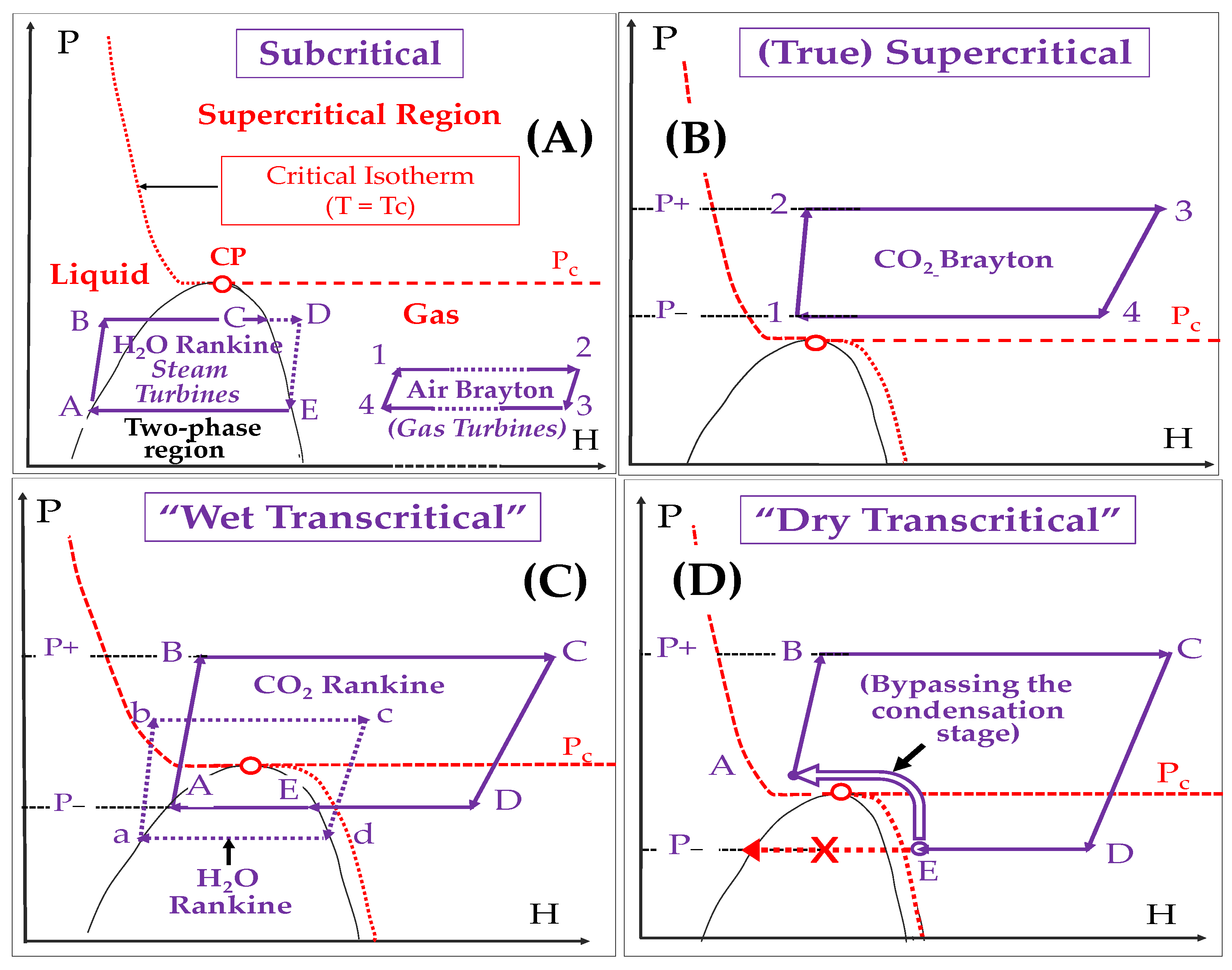
Figure 1 provides a simplified classification of the main types of such large power cycles based on H
2O, air and CO
2, according to their sub-, trans- and supercritical character:
- -
Diagram A shows two subcritical cycles: [A … → D] (steam Rankine) and [1 … → 4] (air Brayton)
- -
Diagram B sketches a “true” supercritical CO2 Brayton cycle: all stages are performed at P > Pc and T > Tc; in other terms, all are located in the supercritical region and there is no condensation step
- -
Diagram C represents two “wet transcritical” cycles that use H2O ([a… → d]) and CO2 ([A… → D]) as respective fluids; stages A → B (and a → b) are performed in the supercritical region; condensation occurs at stages E → A and d → a, respectively; these are Rankine cycles in their simplest form
- -
Diagram D refers to a “dry transcritical” CO2 cycle: in this variant, we bypass the condensation step using a sequence of compression and cooling stages, whose details will be given in paragraph 4.2.3; this cycle can be assimilated to an intercooled Brayton.
It should be stressed that actual industrial cycles are much more sophisticated.
4. Fundamental Properties of sCO2 Cycles
In this section, we will focus on the “conceptual” advantages and drawbacks of the sCO
2 technology, which result from the specificities of supercritical fluids [
25] and the design of the corresponding cycles.
To do that, we will assume “ideal” conditions, i.e., we will take all isentropic efficiencies of compression and expansion equal to 1 and neglect all pressure drops and mechanical/electrical/magnetic losses. This will of course result in optimistic performances but will provide a common basis on which (i) to quantify the conceptual assets of sCO2 cycles with respect to conventional ones and (ii) to compare the merits of distinct cycle types and architectures.
Figure 2 shows a general P-H diagram that will be used in our analysis of sCO
2 power cycles. One distinguishes four regions around the critical point (“CP”): the liquid, the supercritical (P > Pc and T > Tc), the real gas and perfect gas regions.
The portion of the supercritical region in the lower (respectively high) enthalpy zone will be called “near-supercritical” (respectively “far-supercritical”).
4.1. The Conceptual Strengths
The two fundamental advantages of sCO
2 cycles are (1) elevated efficiency and (2) reduced component sizes [
26,
27,
28]. We will show that both result from a single property, namely the high density of supercritical fluids, as compared to gases and vapors used in the subcritical cycles that are represented in
Figure 1A.
4.1.1. Efficient Compression and Expansion Result in High Cycle Efficiency
The elemental compression or expansion work (
δw) involving a unit mass of fluid and performed in reversible conditions (i.e., at constant entropy), is given by the following equation:
where
and
are the specific enthalpy and volume of the fluid and
ρ its density.
In other terms, when the density increases, the corresponding work decreases and vice versa.
When looking now at the iso-density lines plotted in the P-H diagram of
Figure 2, we see that:
- -
Density is high (ρ ≈ 400–600 kg/m3) in the zone close to the critical point (“CP”): the “near-supercritical” region
- -
It decreases (down to 100 kg/m3) in the higher enthalpy (“far-supercritical”) region.
- -
It still decreases in the “real gas” region (ρ ≈ 50 kg/m3) and even more in the nearly-perfect CO2 (pink area) region: there, ρ drops to around 10 kg/m3 below 10 bar and its value at 0 °C-1 atm falls to 2 kg/m3.
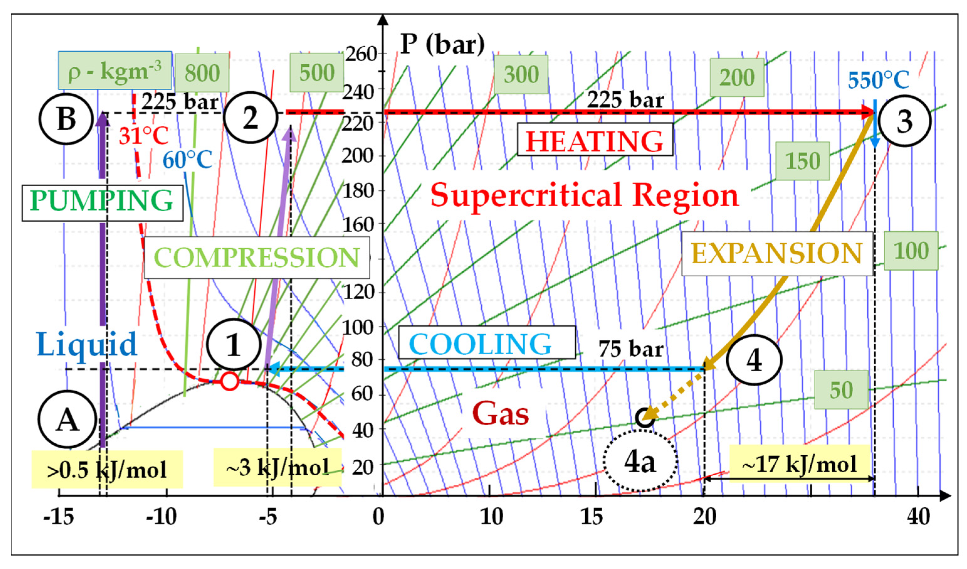
Let us look now at a basic (non-recuperated) supercritical cycle (
Figure 3) for which we take the following input data: (T–, P–) = (45 °C, 75 bar) and (T+, P+) = (550 °C, 225 bar). From Equation (1), we deduce the following:
- -
The reversible mechanical work (W
compr) consumed for the compression performed in the near-supercritical region is very low; indeed, in stage 1 → 2,
ρ = 600 kg/m
3 (
Figure 1) and W
compr ≈ 3 kJ/mol.
- -
Reversely, the expansion work (Wexp) which is performed in the far-supercritical region is high; in stage 3 → 4, Wexp is approximately equal to 17 kJ/mol.
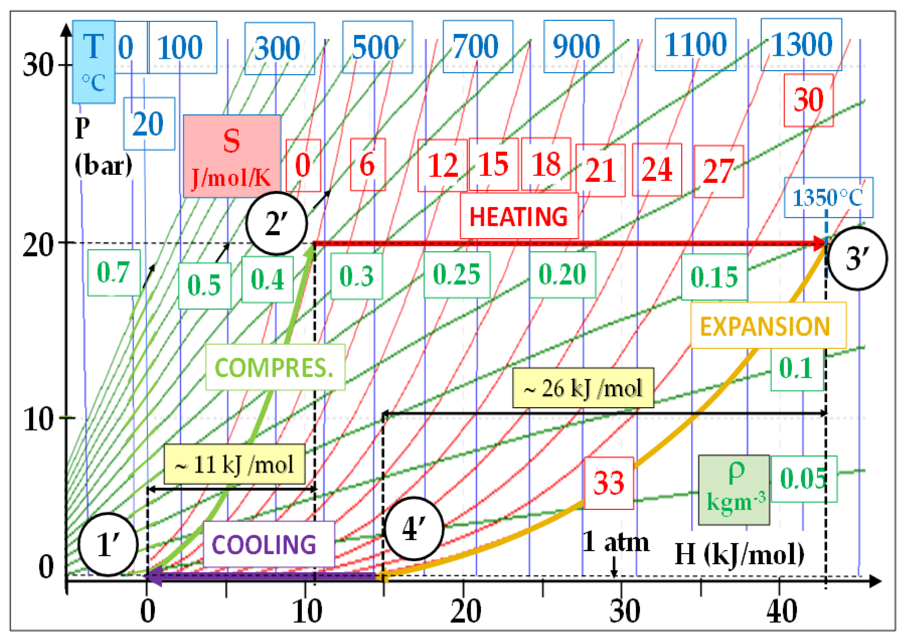
Figure 3 shows that the energy consumed by the reversible compression represents approximately 18% of that delivered by the expansion. In comparison, this percentage is about 42% (11/26) in a typical F-class gas turbine, as shown by
Figure 4. Moreover, this ratio is still lower in a supercritical steam cycle: around 4%.
Indeed, we must note that the density is the highest (and W
compr the lowest) in the liquid region, where
ρCO2 typically exceeds 800 kg/m
3. This allows for very efficient pumping stages, which represents an inherent efficiency merit of Rankine cycles: for example, the pumping stage A → B (
ρ ≈ 900 kg/m
3) consumes hardly 0.5 kJ/mol (
Figure 3).
Such favorable compression and expansion stages result in excellent cycle efficiencies. This will be illustrated by the remarkable performance of the most advanced sCO
2 cycles which will be described in
Section 5.
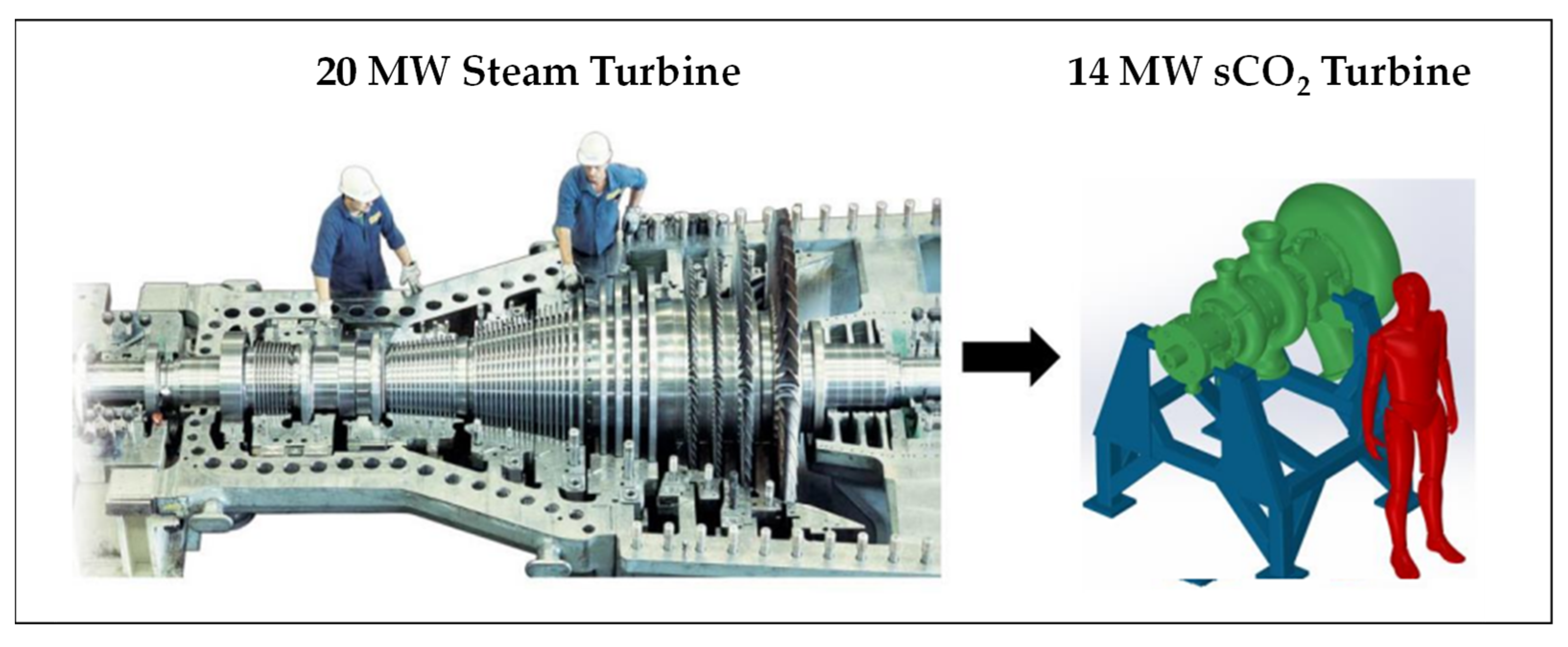
4.1.2. Compactness of sCO2 Power Units
The second key advantage of sCO
2 cycles is the dramatic reduction in size of cycle components, which is again correlated to the high density of supercritical CO
2 [
29,
30].
Indeed, to control the level of turbulence of the fluid and minimize the resulting losses in static pressure and efficiency, the cross-section of a turbomachine is designed proportional to the volumetric flow of the fluid, i.e., inversely proportional to its density.
Although the sCO2 machines have higher mass flow rates (for the reasons that will be set out in paragraph 4.2.1), their sizes are significantly smaller due to the fluid density effect.
Figure 5 presents a notional comparison between the diameters of a sCO
2 turbine and a steam turbine (“ST”) that deliver power output of the same order [
31]. A quantitative comparison will be proposed below (§ 5.1).
It is worth noting that the rotation speed of the shaft also conditions the size: the higher the speed, the smaller the diameter.
4.1.3. Other Strengths Linked to Favorable Properties of the CO2 Molecule
SCO2 cycles have other important merits linked to advantageous properties of the CO2 molecule.
Firstly, unlike H2O that has elevated critical properties (374 °C, 221 bar), the critical point of CO2 is easily accessible (31.1 °C, 73.8 bars).
Additionally, compared to hydrocarbons used in Organic Rankine Cycles (ORC), CO
2 does not ignite or explode; its toxicity (risk of asphyxiation) occurs at a much higher concentration in the air and its GWP and ODP data are much lower: for example, the GWP of propane is 3 while that of CO
2 is 1 by definition [
32]. It boasts also a very high thermal resistance, which allows for a wide operation temperature range in power cycles, from for example 200 °C (including e.g., heat recovery cycles and geothermal applications [
33]) up to 500 °C (including solar [
34] and nuclear [
35] applications). All these characteristics make CO
2 a versatile cycle fluid: while the usages of steam and air are limited respectively to Rankine and Brayton cycles, CO
2 can be used in both and, moreover, not only within power cycles but also within refrigeration ones.
Finally, the closed nature of these cycles results in rather clean circuits, apart from the need to stop wear particles by filtration. This contrasts with the complex and costly water treatment of steam cycles and the need of periodical cleanings of gas turbines due to the progressive fouling of their compressors by dust and salts from ambient air.
4.2. The Conceptual Drawbacks
4.2.1. Low Pressure Ratios Cause Low Specific Power Outputs
Although supercritical cycles operate at high pressures, they have low pressure ratios. Indeed, given that the pressure of a true supercritical cycle (Brayton) must exceed 73.8 bars in all stages, the pressure ratio (“Rc”) turns out to be rather limited. For example, if we reasonably limit the value of P+ to 250 bar and start compression at P– = 75 bar, then the Rc is barely 3.3, leading to low enthalpy drops and limited expansion works in the power turbine.
In contrast, modern gas turbines boast Rc data ranging from 20 to 30. Although transcritical condensation (Rankine) cycles have P- values lower than 73.8 bar (
Figure 1C), they are subject to a similar limitation because reducing P– too much would require increasingly colder heat sinks. Non-condensing transcritical cycles (called “dry transcritical” above) escape this limitation since P- can be set below Pc (
Figure 1D): taking for example P– = 30 bar results in Rc climbing to 250/30 = 8.3. However, this is at the expense of complexity since there is need for additional compression/cooling sequences.
Low Rc values result in low turbine outputs. We can define the “specific power output” (SPO) of a power generation unit as its electrical output (Wel) divided by the mass flow rate (Qm) of the fluid passing through the cycle, i.e., SPO = Wel/Qm.
Table 1 compares, in their orders of magnitude, the SPOs of three usual cycles, namely: steam-Rankine; air Brayton and sCO
2 Brayton. The SPOs of the sCO
2 cycles turn out to be roughly 3 times (respectively 15 times) lower than that of an F-class gas turbine cycle (respectively of a steam cycle). Nevertheless, this does not prevent the reduction in equipment size mentioned above owing to the much greater density of supercritical CO
2.
4.2.2. Low Specific Power Requires Intense Heat Recuperation
As the turbine generates little power, it discharges still hot CO2. Heat recuperation at its outlet, before heat rejection, is then desirable to improve efficiency. In other words, sCO2 cycles require intense thermal recuperation.
4.2.3. The Narrow Operability of sCO2 Rankine Cycles (Figure 1C)
The critical temperature of CO2 is rather low (Tc = 31.1 °C). Consequently, heat sinks capable of completely condensing CO2 must have a maximum temperature of about 25 °C. Unfortunately, such cold heat sinks are not so common and will become less available due to the global climate change, which is a strong handicap for sCO2 Rankine cycles.
Two options can be explored to resolve this issue:
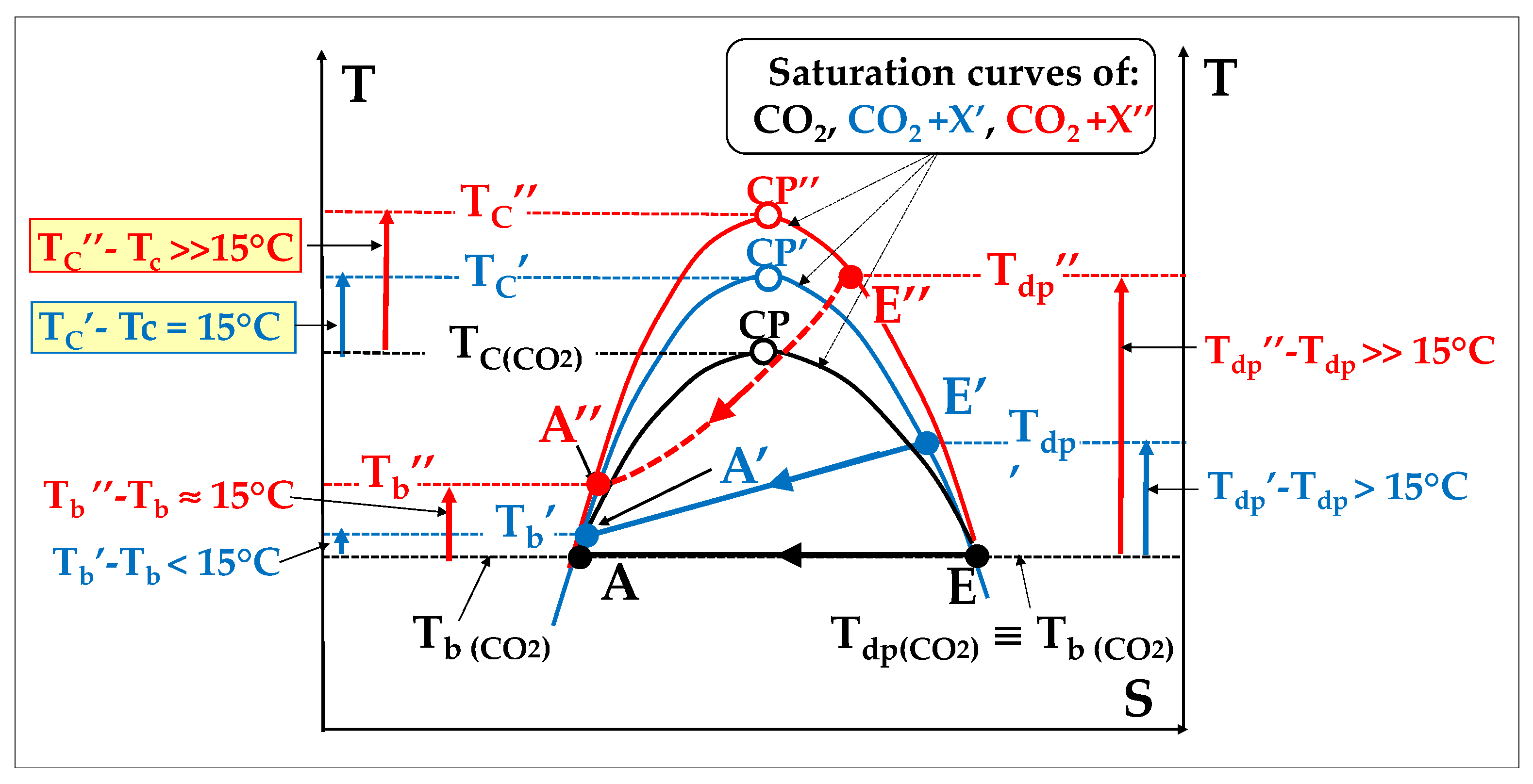
Option A—Attempts to increase the critical temperature [
36,
37]:
The first possible approach consists in looking for a substance “X” which, once blended with CO
2, would increase the Tc value by e.g., 15 °C. To keep the content of this article balanced, the studies made in that respect will be set out in
Appendix A.
However, ultimately, these attempts show that it looks impossible in practice to find such molecule that would be acceptable from an EHS and cost standpoint.
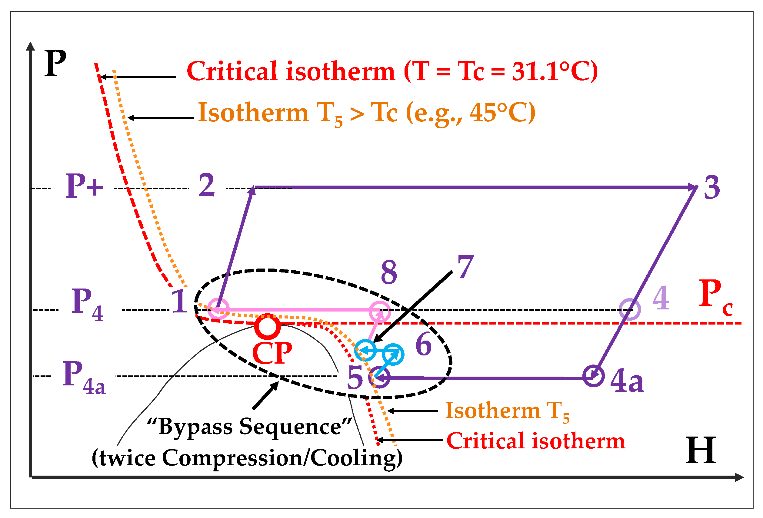
Option B—Moving from a “wet transcritical” to a “dry transcritical” cycle:
The second approach consists in passing from a “wet transcritical” (i.e., Rankine) to a “dry transcritical” cycle (
Figure 1D) since the latter does not impose any conditions on the heat sink temperature.
In fact, a “dry transcritical” cycles, as it is sketched in
Figure 1D and in more detail in
Figure 6, offers an interesting option to both address the narrow operability of the Rankine cycle (represented in
Figure 1C) and improve the efficiency of a true supercritical cycle (
Figure 1B).
In comparison with
Figure 1B, the expansion stage 3 → 4 is extended below the critical pressure, up to a point 4a corresponding, for example, to P
4a = 30 bar. Then, compared to
Figure 1C, the cooling stage is stopped when reaching an isotherm at a temperature slightly higher than Tc (for example at point 5 where T
5 = 45 °C)
A “bypass sequence”–here a double process of (compression/cooling)–replaces the condensation step of
Figure 1C and allows to return to point 1 which is located on the T
5 isotherm. This cycle variant thus allows to expand the CO
2 below the CP and to close the cycle without crossing the condensation dome. It is transcritical by nature but remains “dry” since it is without condensation, which dispenses from a low temperature heat sink.
It has also two additional advantages from an efficiency point of view:
- -
The Rc value becomes increased from (P3/P4) to (P3/P4a): we thus escape the pressure ratio limitation suffered by true supercritical Brayton) cycles
- -
There are other improvements in efficiency, which again result from Equation (1); indeed, referring to the chart of
Figure 3, the extended expansion causes the density to pass from about 75 kg/m
3 (point 4) to about 50 kg/m
3 (point 4a); moreover,
ρ increases again during the recompression stages from point 5 to point 8.
This option has been actually exploited in the Allam cycle [
3,
38] as well as in Echogen’s EPS 100 project [
30,
39].
However, a main drawback is the need for additional compression and cooling stage(s) to perform the bypass sequence. Additionally, it cannot be combined with the double recuperation/recompression cycle described below (§ 5.2), as it would generate excessive added complexity.
In conclusion, although sCO2 transcritical Rankine cycles can be used in winter in cold and temperate climates, their operability is weak in summer and in hot climates. This is the main reason why they are not actually used for power generation, being more suitable for refrigeration applications.
This apparent impossibility to improve the operability of sCO2 Rankine cycles is very detrimental to the deployment of the sCO2 technology, because these cycles would have provided interesting performances in the field of heat recovery at low temperatures, where Brayton cycles are less efficient, as it will be shown in detail at § 6.2. This was the objective of the EPS100 project which seems however to have been interrupted.
Therefore, the rest of this article will focus on sCO2 Brayton cycles.
4.2.4. The Gap between Conceptual and Practical Evaluation
The conceptual evaluation outlined above, shows very favorable thermodynamics but it relies on ideal conditions. In reality, the actual isentropic efficiencies of turbomachines have a strong impact on performances. Moreover, the technology of sCO
2 power cycles is sometimes said to be in its “infancy” [
40] and there is still progress to be made to reach optimized performances. The technical aspects of this topic, which are rarely covered in the academic literature, will be tentatively addressed in
Section 7.
However, before tackling these engineering aspects, we need to provide a description of the possible architectures for sCO2 Brayton cycles and assess their respective performances.
5. Outstanding Architectures of sCO2 Brayton Cycles
As already stressed, sCO2 cycles require intense heat recuperation to compensate for the low compression ratios and limited outputs of the power turbine. Therefore, we will omit non-recuperated cycles (denoted as “option 0”) and will focus on the most promising architectures.
In doing so, we will use the following inputs: (T–, T+) = (45, 550 °C) and (P–, P+) = (75, 225 bar) corresponding to an Rc of 3; the pinch temperatures of heat exchangers are 10 °C.
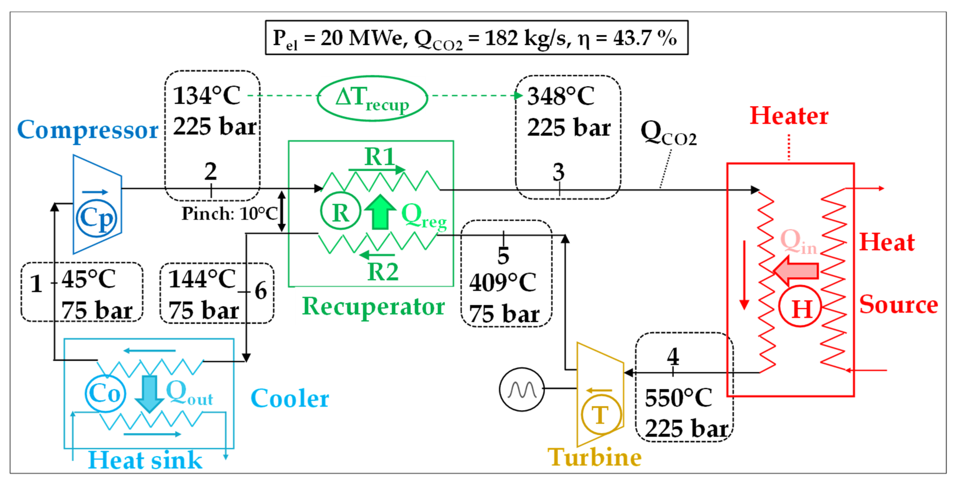
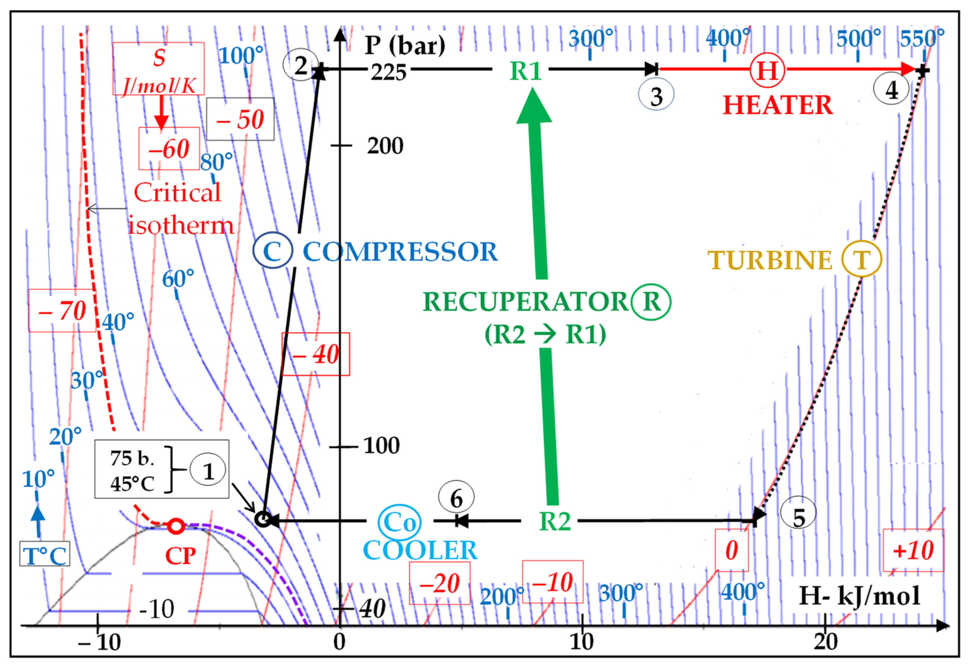
5.1. Architecture 1: Simple Thermal Recuperation (or “Simple Cycle” Configuration)
Figure 7 shows a sketch of a 20 MWe Brayton sCO
2 cycle that comprises a CO
2 heater (H) and a single recuperator (R). The corresponding P-H diagram is presented in
Figure 8 [
41].
The recuperator R transfers some heat from the hot, LP branch (mark R2) to the colder, HP branch (mark R1) of the cycle. Doing so, the HP CO2 stream has its temperature increased by an amount noted “∆Trecup” before it enters the heat source, which diminishes the heat to be extracted from the latter.
This configuration is sometimes called “simple cycle” owing to the use of a single recuperation.
The results of the thermodynamic simulation (listed in
Figure 7) indicates that the CO
2 through-flow necessary to generate 20 MWe is 182 kg/s, which corresponds to an SPO of 110 kJe/kgCO
2.
The heat recovery rate is truly considerable since the temperature increases by ∆Trecup = T3 – T2 = 214 °C at the entrance to the heat source.
The thermodynamic simulation shows that the intrinsic electric efficiency of this simple-recuperated sCO2 cycle is ηintr = 43.7%.
It would be reduced by more than half, falling to 20%, if we removed the recuperator, which would be the “option 0” that is in fact never used due precisely to its very poor efficiency.
Back to the size reduction effect:
As mentioned above, the cross-section of a turbomachine is sized to be proportional to the volumetric flow (Qv in m3/s) of the fluid, or-which is equivalent-to the ratio between its mass flow rate (Qm in kg/s) and its density (ρ in kg/m3).
Table 2 compares the sizes of (i) the 20 MW sCO
2 turbine involved in the “simple cycle” architecture above and (ii) a conventional 20 MW steam turbine (ST).
The steam turbine has both an HP and an LP casing. The comparison is made at turbine discharge where the gas speed is greatest. The calculation shows a diameter twice greater for the HP steam casing and about 12 times greater for the LP steam casing.
Despite these substantial gains in efficiency and size, this
architecture 1 faces an efficiency limitation, which comes from the fact that the heat capacity (Cp) of supercritical CO
2 decreases significantly when its pressure decreases, as illustrated by
Figure 9 [
28].
Indeed, the cold CO
2 stream in the HP branch (R1) has a higher Cp than the hot CO
2 stream in the LP branch (R2). This causes an unbalanced temperature profile inside the recuperator. More precisely, we can observe in
Figure 7 and
Figure 9 that the HP CO
2 stream heats by only 204 °C (348–144) while the LP CO
2 stream cools by 265 °C (409–144).
5.2. Architecture 2: Double Recuperation and Recompression (Recompression Closed Brayton Cycles or RCBC)
To overcome this limitation, we can create a second exchange between the HP and LP CO
2 streams, which however requires recompressing a fraction of the LP-CO
2 to inject it into a second recuperator (
Figure 10) [
42].
To do this, the stream of CO2 leaving the first recuperator (the “LT” one) is divided, at point P, between the cooler (mark Co) and a “recompressor” (mark RC), using a three-way valve (V) which provides a variable flow splitting ratio. This recompressed fraction “x” is injected into the HP branch of a second recuperator (the “HT” one).
To designate this new cycle architecture, we will adopt, in the rest of this article, the expression “Recompression Closed Brayton Cycle”, and more shortly the acronym “RCBC” to comply with the most widespread use.
The inputs (T–; P–; T+; P+ and pinches) used in the simulations are unchanged. To produce again 20 MWe, the main CO2 flow (crossing the turbine) must be 200 kg/s (i.e., an SPO of 100 kJ/kgCO2) and the optimum “recompressed flow” must be 47.8 kg/s, corresponding to fraction x = 0.239.
The main results are reported in
Figure 10. The intrinsic electric efficiency η
intr is 48.3%, which is 4.6 points more than in
architecture 1.
It is therefore clear that the RCBC variant significantly improves the heat recovery process as we have: ∆T
recup = T
4 – T
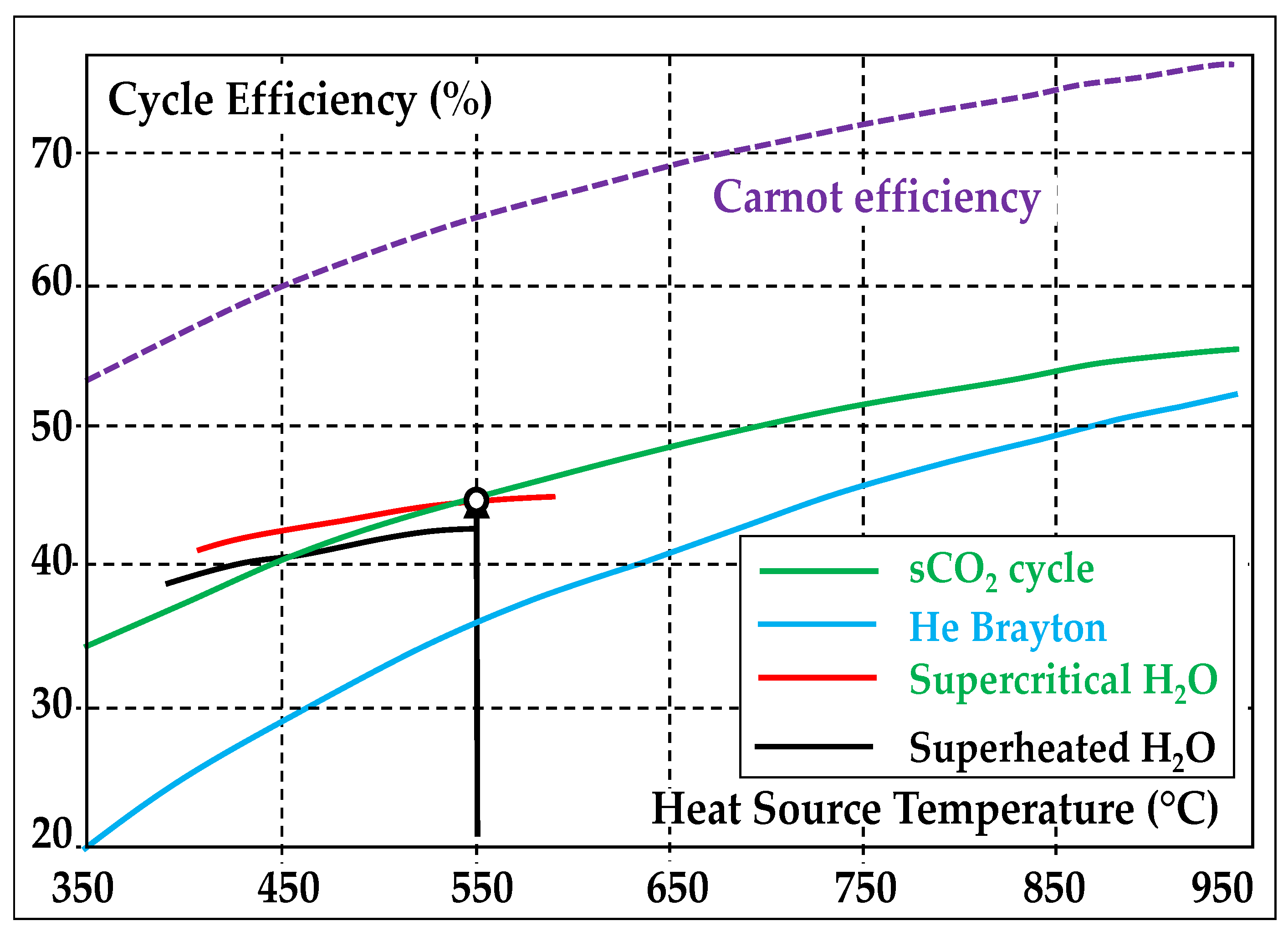
2 = 249 °C (versus 204 °C in architecture 1), providing thus 4.6 additional points of efficiency. This efficiency level honorably compares with most modern simple-cycle gas turbines that are fired at 1400–1500 °C. As a result, RCBC cycles outperform, above 550 °C, all other cycles operating with similar heat source temperatures (
Figure 11) [
43,
44].
However, this comes at the expense of the simplicity of the cycle.
5.3. Other Possible Architectures
Architectures 1 and 2, which involve a single CO
2 heater, are of interest in applications where the heat source is at a fairly constant temperature and its heat can be easily extracted using a single heater and a heat carrier (at best a liquid) that circulates in the hot branch of the heater (line 9–10 of
Figure 11). This is the case (i) in solar units, e.g., in CSP plants using molten salt as heat carrier, with heat source temperatures ranging from 500 to 700 °C [
45] and (ii) in nuclear units, namely in Small Modular Reactors (SMR) having turbine inlet temperatures in the range of 500–600 °C [
46].
However, other architectures are possible [
47]. Some of them involve two or more CO
2 heaters which become necessary when the temperature window of the recuperation is too wide to be accommodated by a single one. An important example is the recuperation of residual heat from combustion gases, released e.g., by diesel engines or gas turbines. Such an example is covered below (§ 6.2).
6. Two Paradigmatic Applications: Solar Power and Heat Recovery from Hot Gases
In this section, we will illustrate the performances of RCBCs through two important applications. This time, to carry out a closer assessment of the merits and limitations of sCO2 Brayton cycles, we will assess their performances not only in “ideal” but also in “realistic” conditions.
6.1. Concentrated Solar Power Plant (CSPP)
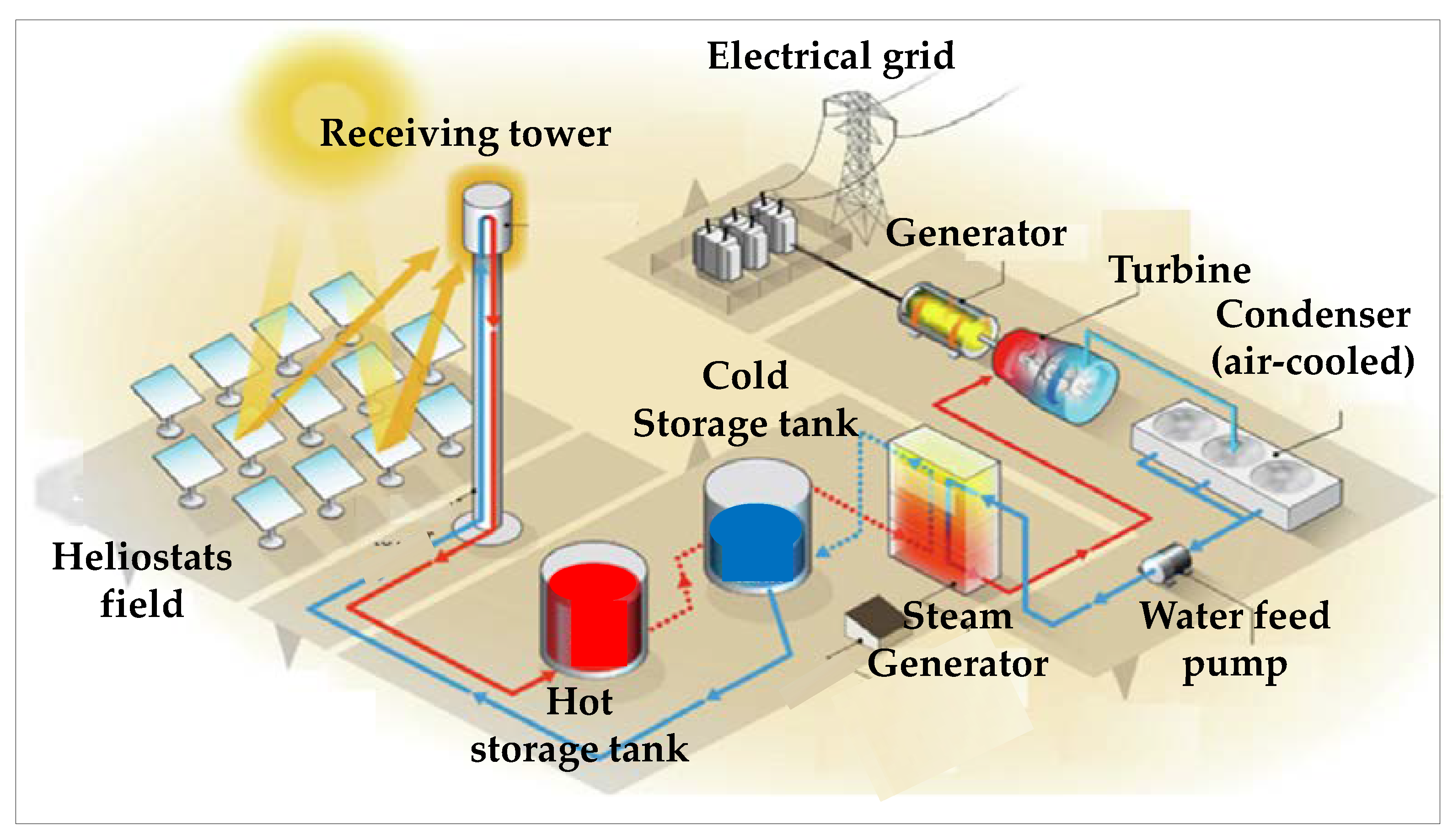
Figure 12 represents a typical CSPP [
48,
49]. Solar energy is reflected by a field of heliostats towards a receiving tower which constitutes the heat source. The heat is extracted by a molten salt (often a eutectic mixture of alkaline nitrates). This heat carrier is stored in a hot tank; it feeds a steam generator, which powers in turn a Rankine cycle and is then collected in a “cold” tank from where it returns to the receiving tower.
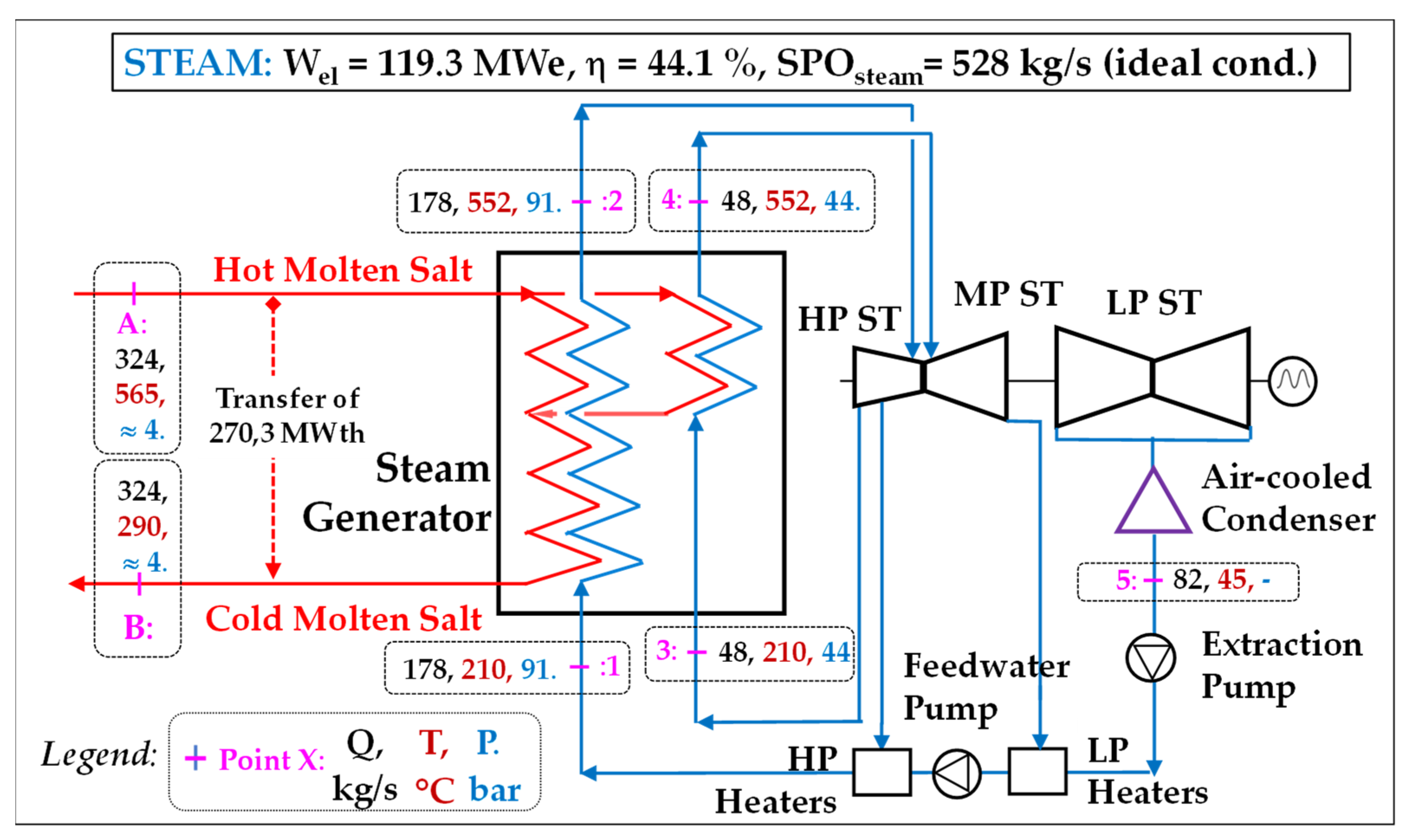
The typical Rankine cycle is sketched in
Figure 13, with the data of the main streams.
It has both superheat (176 bar-552 °C) and reheat (42 bar-551 °C) stages. The heat sink (an air-cooled condenser) is taken at a temperature (T–) of 45 °C which is the condensation temperature of the cycle. The molten salt enters the receiving tower at 565 °C with a flow rate of 324 kg/s and leaves it at 290 °C (the minimum temperature to keep it above the solidus of the salt): there is an exchange of 270.3 MWth in the steam generator. The approach temperature is 13 °C. In these conditions, the “ideal” power output is 119.3 MWe and the efficiency 44.1%; the overall steam flowrate is 226 kg/s with an SPO of 528 kJe/kg.
“Realistic” performances are obtained using a value of 92% for the average isentropic efficiency of the whole steam turbine (values vary from 90 to 95% between the HP, MP and LP casings); the contributions of water pumps are negligible. The actual power is then 109.8 MWe and the efficiency is 40.6%.
6.1.1. Transposition into an sCO2 Brayton Cycle
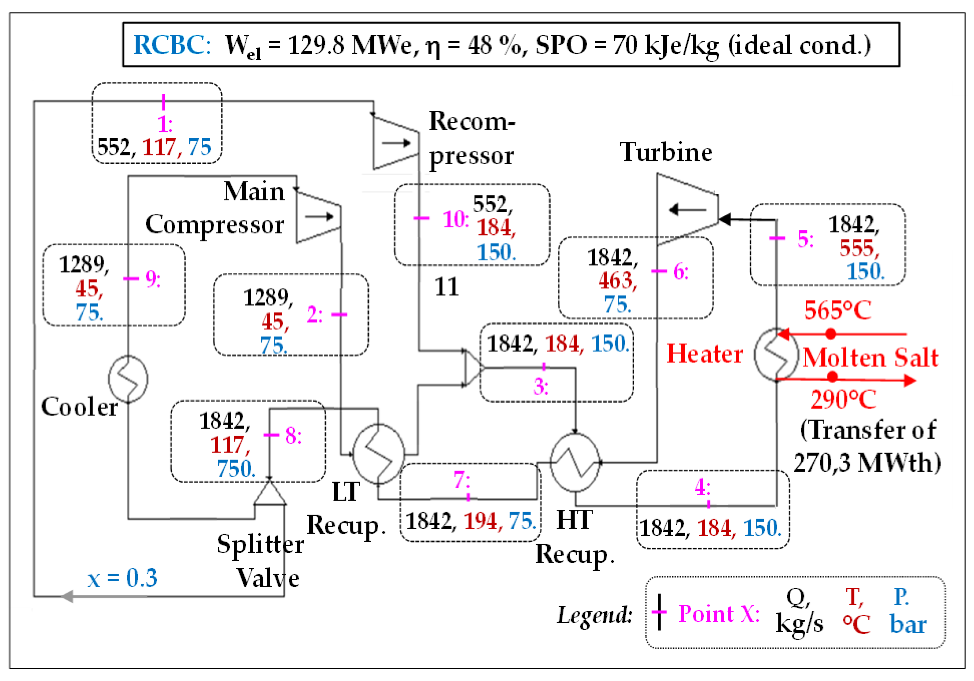
The “candidate” Brayton sCO2 cycle which is chosen to challenge the above Rankine cycle is of the RCBC type as described in § 5.2. It is fed with the same molten salt at 565 °C and exchanges also 270.3 MWth with it. Its evaluation was carried out with the same input data as before: T– = 45 °C and P– = 75 bar.
Figure 14 shows such possible transposition and the results of a corresponding simulation performed firstly in ideal conditions.
The optimum efficiency is reached with the following parameters:
- -
main CO2 flow QCO2 = 1842 kg/s
- -
P+ = 150 bar (i.e., a compression ratio Rc of only 2)
- -
recompression fraction: 30%.
We have also calculated the “realistic” performances, for which we have taken typical isentropic efficiencies of 0.90 for the turbine and 0.85 for the compressors (instead of 1). These values are slightly higher than those retained as objectives in the STEP program (see § 7.1).
6.1.2. Simulation Results of the Candidate sCO2 Cycle and Short Discussion
The efficiency assessed in “ideal” conditions is 48% and the power output is 129.8 MWe: we thus observe a gain of 3.9 points in efficiency compared to the Rankine cycle equipped with superheat and reheat. The SPO is however much lower: 70 kJe/kgCO2.
Nevertheless, in “realistic” conditions, the net power drops to 108.3 MWe and the efficiency to 40%: the RCBC loses 8 points and goes to 0.6 point below that of the steam Rankine cycle (40.6%).
This mediocre result is mainly explained by the fact that the water feed pump of the Rankine cycle is incomparably more efficient than the CO
2 compressors despite the supercritical state of the latter fluid, as it has been already highlighted in § 4.1.1 and illustrated by
Figure 3.
6.2. An Important Application to Reduce Carbon Footprints: Heat Recovery from Combustion Gases
This paragraph deals with the recovery of residual heat carried in the flue gases of a thermal equipment, for example a gas turbine (GT) [
50]. The whole (GT + recovery cycle) will then constitute a Gas Turbine Combined Cycle (GTCC), the GT representing the “topping” cycle [
51] and the recovery cycle being the “bottoming” one [
52,
53]. Incidentally, we can notice that this sCO
2 application profile is identical to that developed in Echogen’s EPS100 project, which employed however an sCO
2 Rankine cycle [
30,
39].
In applications of this type, it is necessary to use several heat exchangers to maximize heat recovery. Indeed, the temperature of the flue gases decreases as the exchange progresses and the operator’s goal is of course to reduce it as much as possible (for example from 550 to 70 °C), in order to maximize the overall efficiency of his GTCC.
Our goal is to see whether an sCO
2 design can become a “challenger” for a two-pressure steam cycle which is the “title order” in contemporaneous industrial GTCCs [
53]. We will then simulate both cycles and compare their performances. This comparison will be carried out in “ideal” conditions and the transition to “realistic” conditions will then be discussed.
The gas turbine is an E-class machine which is fired at a temperature in the range of 1100–1150 °C and generates an output (Wel,GT) of 122.1 MWe, with an electrical efficiency of 33.4%. Its heat consumption is WthGT = 122.1/0.334 = 365.6 MWth (on a fuel LHV basis). The maximum Recoverable Heat is then RHmax = (WthGT − Wel,GT) = 243.5 MWth; this heat is carried by a flow of 412 kg/s of combustion gases (“cg”) that are released at 544 °C.
6.2.1. Design of the “Candidate” sCO2 Cycle
The candidate sCO2 cycle is again of the RCBC type, the most efficient.
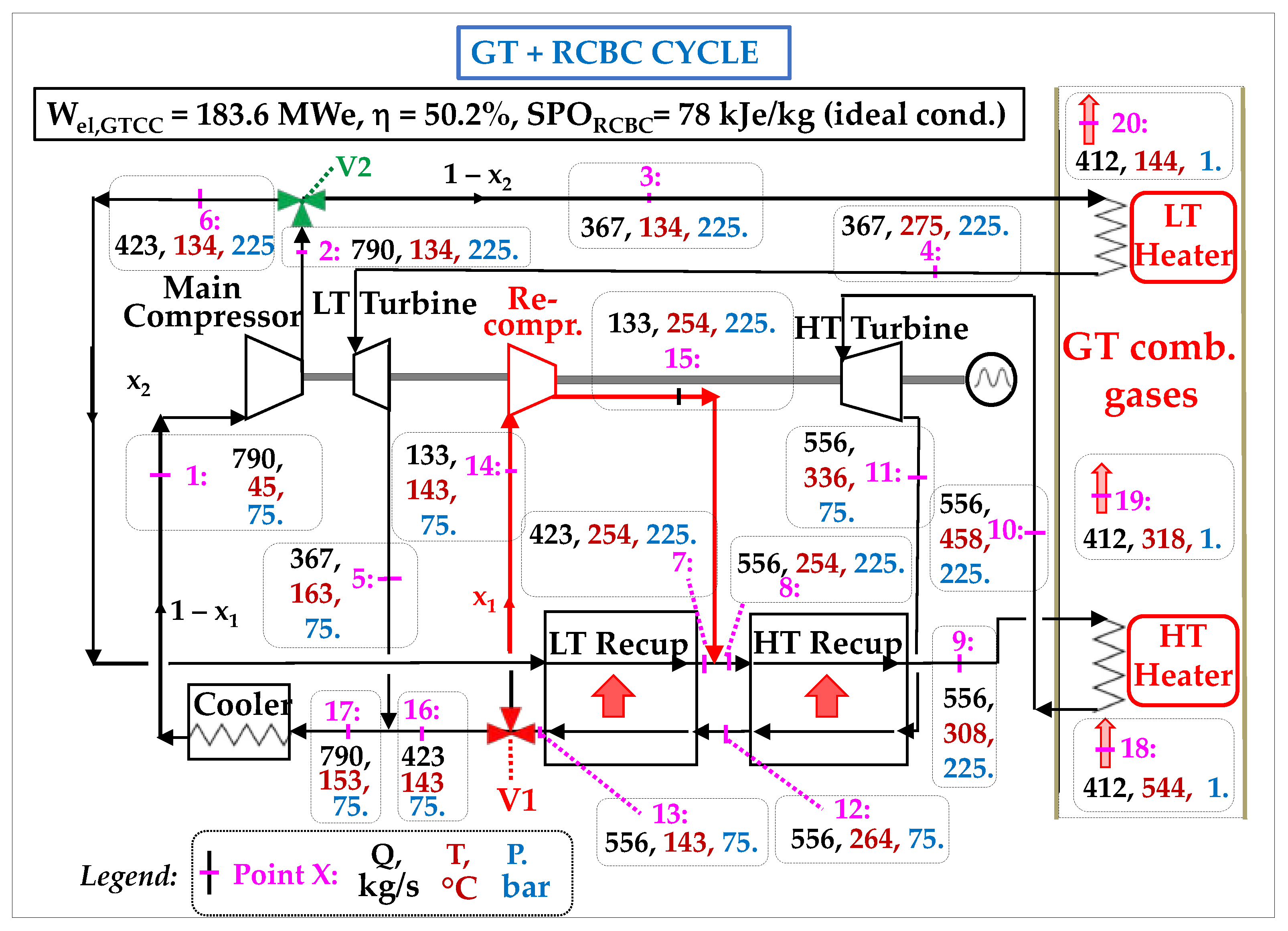
However, this time there is both an HT CO
2 heater and an LT CO
2 heater which capture heat respectively on the hot zone and the cold zone of the flue gas stream (
Figure 15). They are associated with an HT turbine and an LT turbine, respectively. The ratio between the flows of CO
2 directed towards the HT and LT heater is adjusted via a splitter valve V2. The low temperature of that cycle (T–) is again 45 °C and its pressure P– is again 75 bar.
This leads to an “architecture 3” of sCO2 cycle. Thermodynamic simulations performed in ideal conditions and including a sensitivity study, show that the optimal electrical efficiency is obtained with the following parameters:
- -
main CO2 flow: QCO2 = 790 kg/s: it is the flow crossing the main compressor
- -
fraction of recompressed flow: x1 = 133/423 = 0.31
- -
flow splitting between the LT and HT heater: x2 = 367/423 = 0.87.
These optimized operating parameters lead to an electrical power output Wel,sCO2 of 61.5 MWe for this RCBC of architecture 3 and an intrinsic electrical efficiency (ηintr) of 33.7%. We notice that this value is significantly lower than that (48%) we had obtained with architecture 2 (§ 4.2) which involved a single heater and a similar initial (but constant) heat source temperature (550 °C). The heat actually recovered by the two recuperators is RHactual = [Hcg(544 °C) − Hcg(144 °C)] and is equal to 182.5 MWth; the “heat transfer rate” (ηtrans) is thus RHactual/RHmax = 182.5/243.5 = 75.0%.
The net conversion efficiency (ηnet) of this sCO2 cycle is therefore ηnet = ηtrans × ηintr = 0.337 × 0.75 = 0.253: it is the ratio between the electrical power generated by this cycle and the maximum recoverable heat. The temperature of the flue gases downstream of the LT heater is 144 °C, because the CO2 enters it at 134 °C and the pinch temperature is 10 °C.
The specific power output is then SPO = Wel,sCO2/QsCO2 = 61,500/790 = 78 kJ/kgCO2: it is lower than those found with the previous architectures (around 100 kJ/kgCO2).
Finally, it is interesting to deduce the electrical power of the overall GTCC: Wel,GTCC = Wel,GT + Wel,sCO2 = 122.1 + 61.5 = 183.6 MWe and its efficiency, which is equal to that power output divided by the heat input of the GT: ηGTCC = Wel,GTCC/WthGT = 183.6/365.6 = 50.2%.
6.2.2. Design of the Reference Steam Rankine Cycle [53]
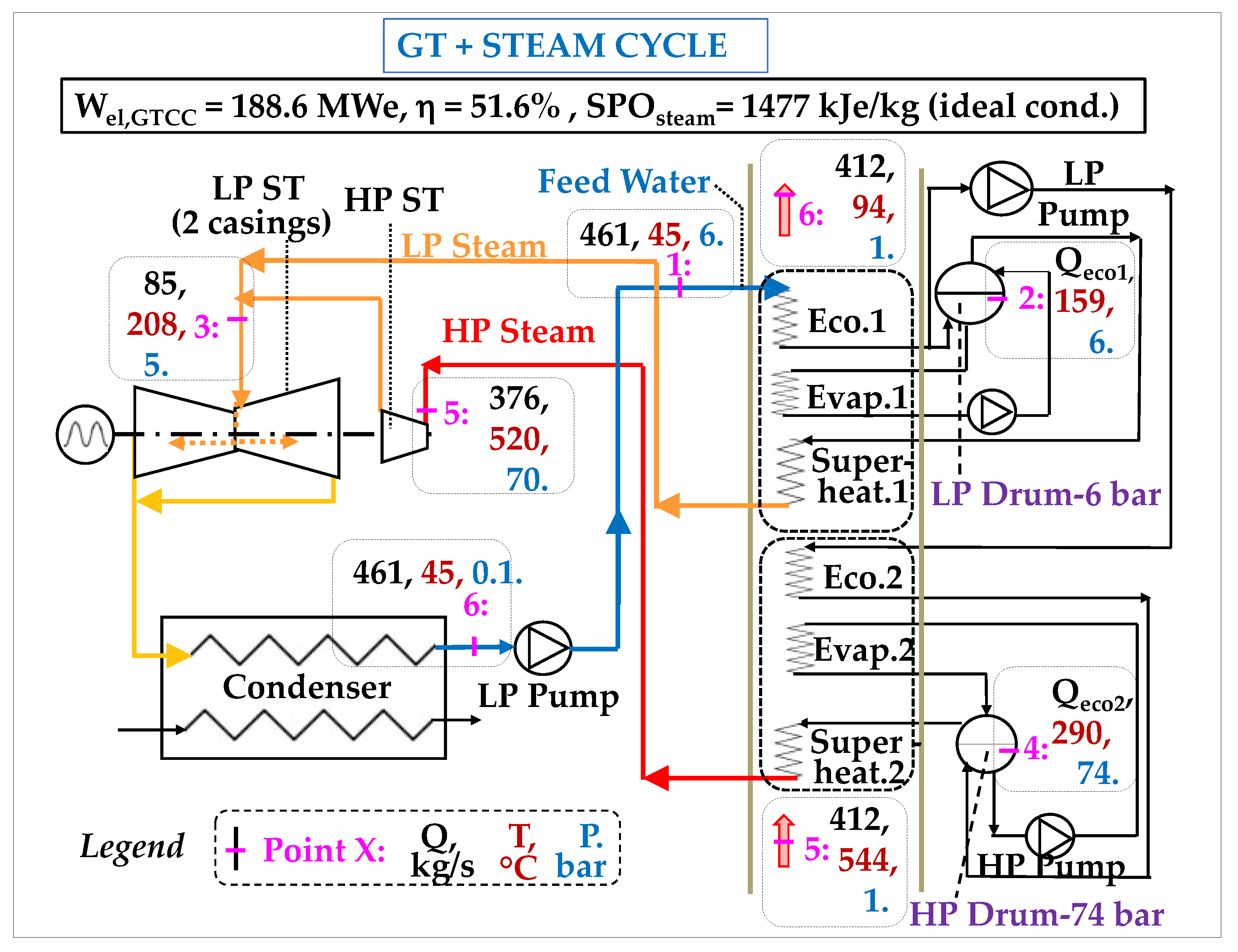
The recovery cycles in GTCCs are classically subcritical, two-pressure steam cycles (for example: 70 bar-520 °C/5 bar-210 °C). We will consider such one exploiting the same residual heat stream.
Figure 16 shows the corresponding diagram along with the properties of H
2O at the main cycle points.
The calculations in ideal conditions show that the power output of this steam cycle is Wel,steam = 66.5 MWe. Its net conversion efficiency is therefore ηnet = Wel,steam/RHmax = 66.5/243.5 = 27.3%. The specific power output of this steam cycle is SPO = Wel,steam/Qsteam = 66,500/45 = 1477 kJ/kg of steam, a value much higher than for the sCO2 cycle (78 kJ/kg of CO2).
The temperature of the combustion gases released into the atmosphre (at the outlet of Economizer No. 1) is 94 °C, significantly lower than the corresponding value in the sCO2 version (144 °C). The heat which is actually transferred to the steam cycle is then RHactual = (Hcg(544 °C) − Hcg(94 °C)) = 202.8 MWth and the intrinsic electrical efficiency is ηintr = Wel,steam/RHactual = 66.5/202.8 = 32.8%.
The heat transfer rate (ηtrans) is RHactual/RHmax = 202.8/243.5 = 83.3%, which is remarkably high.
Finally, the total power of the resulting GTCC is 122.1 + 66.5 = 188.6 MWe and its efficiency is ηGTCC,steam = (Wel,GT + Wel,steam)/WthGT = 188.6/365.6 = 51.6% in ideal conditions.
6.2.3. Discussion
This comparative study between the performances of an RCBC and a two-pressure Rankine cycle operating in ideal conditions, within a multiple heat recovery application, calls for the following discussion.
- -
Intrinsic efficiencies
The intrinsic efficiency of the sCO2 cycle exceeds that of the steam cycle by nearly 1 point (33.7 versus 32.8%). This is essentially because the steam cycle rejects much heat (the totality of the condensation heat of CO2) to the heat sink.
- -
Global performance
However-and this is the most important result-the steam cycle quite significantly outperforms the sCO2 cycle, by 2 points, in terms of overall efficiency: 27.3 versus 25.3%. This translates into a better efficiency of the GTCC using the steam-based bottoming cycle: 51.6% versus 50.2%.
- -
What are the reasons for the success of the steam cycle?
The superiority of the two-pressure steam cycle in this multiple heat recovery application is mainly due to a much better heat transfer (η
trans) which is 83.3%, compared to 75.0%. Indeed, in the steam cycle, H
2O enters the economizer No. 1 as a low temperature liquid (45 °C: point 1 of
Figure 16), while in the sCO
2 cycle, CO
2 is significantly hotter (134 °C: point 3 of
Figure 15) as it has been previously compressed to 225 bar. In other words, while the pumping of water generates virtually no entropy and no temperature increase, on the contrary, the compression of CO
2 significantly increases its temperature despite its supercritical state: this increase here is by 89 °C in the main compressor and by 111 °C in the recompressor. This remark once again highlights the importance of Equation (1) set out in § 4.1.1, knowing that the density of liquid water (about 1000 kg/m
3) is about twice higher than that of supercritical CO
2 (400 to 600 kg/m
3 along its compression stage:
Figure 3); moreover, in Equation (1), the molecular mass of H
2O is about 2.5 times lower than that of CO
2.
However, one can argue that, since the steam cycle employs a greater number of heat recovery exchangers (6 versus 2), increasing their number in the sCO2 cycle would suppress that efficiency gap. In fact, this is not the case because one could not have a CO2 temperature lower than 134 °C at the inlet of these LT exchangers, so that the overall heat recovery efficiency would not improve significantly.
Another a priori possible way to improve the efficiency of the sCO2 architecture would be to equip the compressor with an intercooler which would lower the temperature at the inlet of the LT heater and improve the transfer rate in the latter. However, the additional calories thus recovered would only compensate for those lost in the intercooler.
In summary, the better heat recovery achieved by H2O highlights the interest of using a liquid cycle fluid in the low-temperature portion of a cycle and, more generally, in low-temperature recovery applications.
Overall, the performance of Brayton sCO2 cycles proves limited in the field of low temperature heat recovery, essentially due to (i) the impossibility of having, after compression, a CO2 carrier at a temperature below, say, 100 °C to maximize heat capture and (ii) the need for a relatively high number of turbomachines which destroy considerable amounts of exergy; in this example, four of them are used: two compressors and two turbines.
In this regard, it is really detrimental that the sCO2 Rankine route is hampered by its insufficient operability, as it would more efficiently challenge the steam option, since the use of colder, liquid CO2 would enable capturing significantly more heat at the LT heater and would give higher flexibility for alternative design variants as it is the case with H2O.
6.3. Conclusions of the Two Comparative Studies
We have assessed RCBC cycles in two types of paradigmatic applications.
6.3.1. RCBCs Operated with Hot Heat Sources
- -
RCBC fired with heat sources at say 550 °C or more have a strong efficiency potential which raises them to the first place, before all conventional cycles operated at similar temperature (T+) levels.
- -
However, this advantage vanishes when one considers not ideal but more realistic performances of turbomachines, using levels of isentropic efficiencies congruent with those currently planned in sCO2 development projects.
6.3.2. RCBCs Operated in Heat Recovery Mode with Multiple Heat Exchanges
- -
The heat recovery rate achieved by supercritical CO2 in multiple heat recoveries is lower than that achieved by liquid H2O (75% compared to 83.3% in our study)
- -
Moreover, in comparison with the steam cycle and despite the supercritical state of CO2, there is a greater destruction of exergy especially during the pressure increase stages. This handicap is magnified by the need to use of two compressors. Incidentally, the exergy destruction is greater in the recompressor than in the compressor, because, in the former, the intaking CO2 is hotter and less dense than in the latter.
- -
Finally, the handicap of the sCO2 cycles would be significantly increased if we compared the performances no longer in ideal conditions but in more realistic conditions, using realistic isentropic efficiencies of turbomachines (significantly lower than 1).
In both applications, a significant jump in turbomachine performances appears necessary to improve the ranking of sCO2 Brayton cycles and fully express the potential of this technology.
7. What Are the Challenges Posed by the Industrialization of sCO2 Power?
At this stage, it is time to try to understand the reasons for the relatively slow industrialization process of sCO2 cycles.
In this study, the comparison between RCBCs and steam cycles set out above will be important to quantify the progress to be made in turbomachinery if we want to see sCO2 competing with conventional cycles and becoming active in the energy transition.
As pointed in the introduction, the foundations of the sCO2 technology were established at the end of the 1960′s and, since then, numerous development programs have been deployed worldwide to transpose it into industrial prototypes, first in the low power range and, more recently in a larger range.
Despite obvious progress, these efforts have not yet resulted in industrial designs allowing the release of medium to large power units. Amazingly, this delay is little discussed in the academic literature, probably due to the high engineering rather than purely scientific content of this subject. This situation contrasts with the great number of non-applicative publications devoted e.g., to cycle architectures variants.
In fact, most of the relevant information available on the actual experimental progress comes from a limited number of technical reports written by the developers themselves [
30,
39,
54,
55]. These reports contain complex and very specialized engineering considerations. In this context, the present discussion does not pretend to provide an authoritative view about the progress of the technology. It is rather an attempt–as objective as possible–to identify and document the underlying technological locks and challenges, relying on the (scarce) published information.
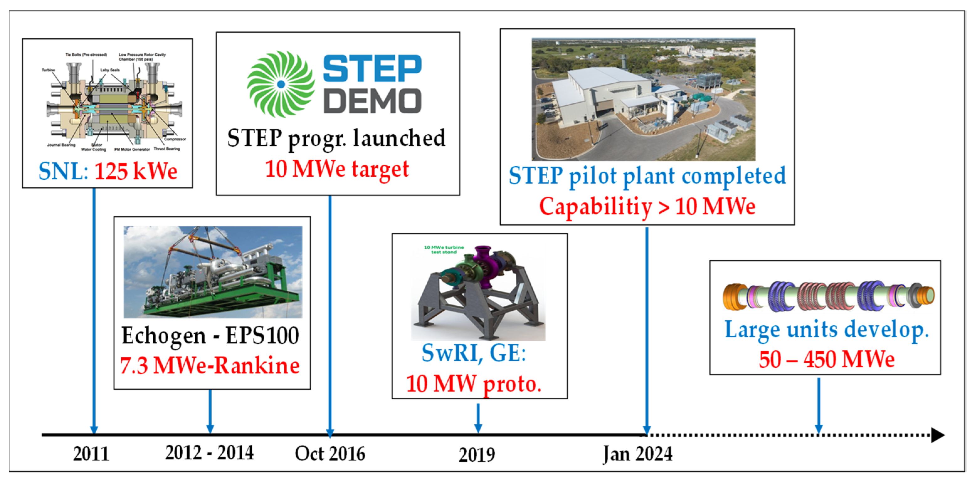
Figure 17 summarizes some key stages of developments carried out to date and planned for the future. Only most important ones are reported as several other programs have been/are conducted namely on small scale units [
24]. The STEP (Supercritical Transformational Electric Power) program represents the most coherent and continuous industrialization effort. It started in 2016, being subsidized by the US DOE and conducted the US GTI, the SwRI and GE as lead partners.
The following analysis focuses primarily on what can be considered the critical aspects of a RCBC designs, which represents the most promising sCO2 cycle architecture.
7.1. Basic Design Options Put Forward for sCO2 Power Plants of the 50–450 MWe Classes
The discussion below will deal with the technology of turbomachines since these components represent the stumbling block of any sCO2 cycle development program. It does not attempt to trace the detailed progress in the development of industrial sCO2 prototypes, which began in the mid-2010s, mainly with funding from the US DOE, and is moreover subject to intellectual property rights. The objective here is rather to illustrate the strong design specificities of these components by referring to a few selected examples of preliminary concepts already published.
A first complication encountered during the development of large sCO2 turbomachines regards the extrapolation of designs from the low- to the high-power range. Small turbomachines accommodate for high speeds (several tens of thousands of rpm). In contrast, larger ones require limited rotation speeds (e.g., 3600 rpm in the USA and 3000 rpm) because of much larger centrifugal forces acting on the blades and the rotor disks, due to higher masses and moments of inertia; incidentally, other considerations are relevant, including the “velocity triangle” and the feasibility of synchronization with the grid.
A first series of such preliminary concepts for turbomachine components was published in 2016 in two articles [
54,
55], at the end of the SunShot program and with the perspective of devising large industrial units (up to 450 MWe). In that study, the announced isentropic efficiency targets were as follows:
90.6% for the power turbine;
83% for the main compressor and
80.1% for the recompressor.
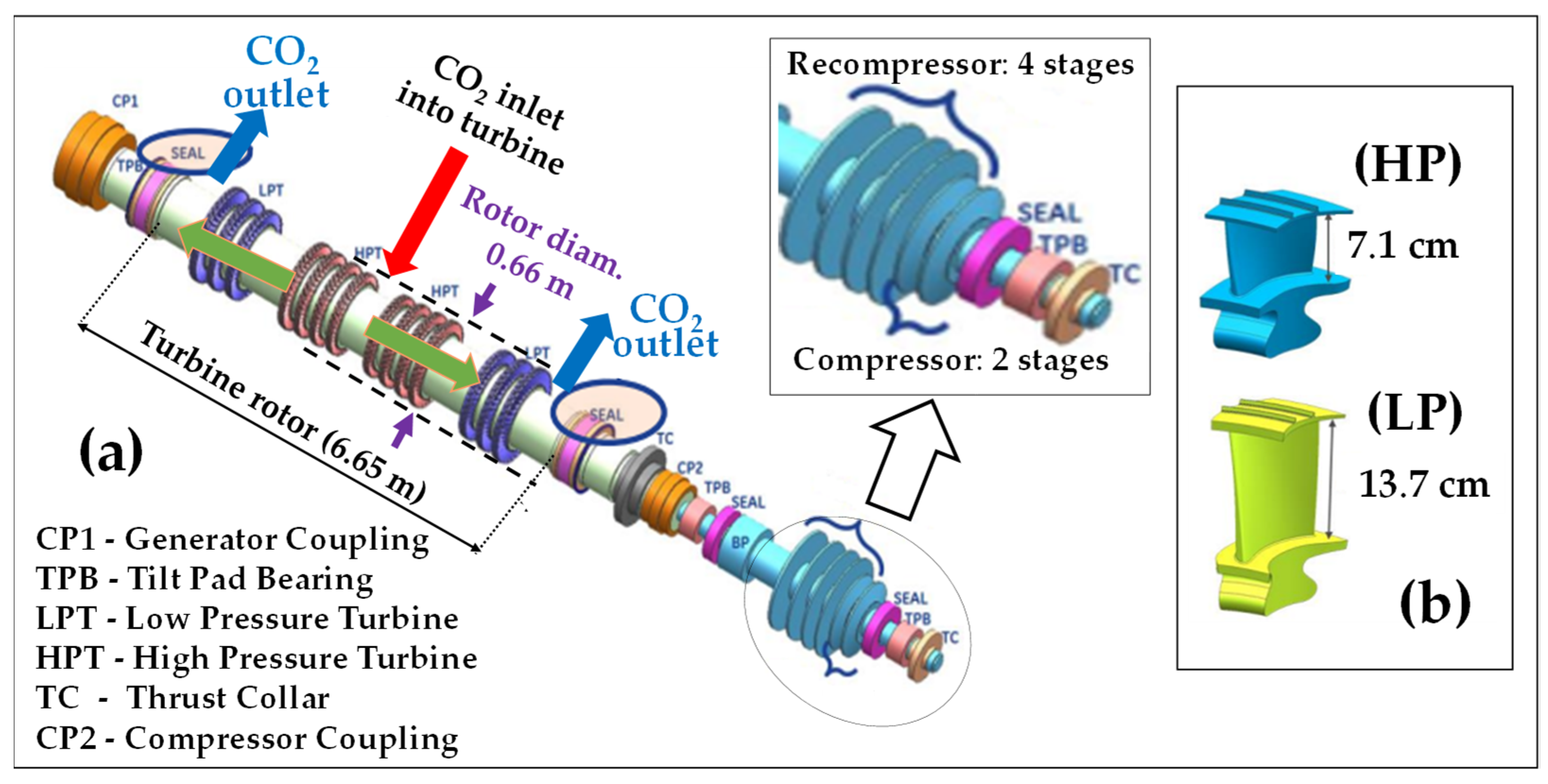
These articles proposed an ingenious concept in which the rotors of the turbine (3 HP + 3LP stages), the main compressor (radial; two-stage) and the recompressor (radial; four-stage) are all assembled on a single shaft.
Figure 18 shows this arrangement as well as notional geometries for the high- and low-pressure blades of the turbine.
The turbine was devised to be axial with symmetric dual-flow, like LP steam turbines of that power class. The compressor and recompressor were instead devised centrifugal (or “radial”) which is made possible by the limited compression ratio needed, knowing that radial compressors can achieve higher compression ratios per stage than axial ones, thus occupying less axial length on the shaft.
- -
the very short length (less than 7 m) of the space occupied by the turbine rotor section, compared to conventional steam and gas turbines constructions
- -
the quite homogeneous geometry of the turbine blades along the different stages and their “lilliputian” sizes, these two points being explained by the low compression ratio, the high density and the low compressibility factor of supercritical CO2.
We are also struck here by the minute axial lengths occupied on the shaft by the two rotors of the compressors; the reason for the larger dimensions of the recompressor is that it admits hotter, less dense CO2.
These design features therefore contrast radically with those of large contemporary steam and gas turbines. In the latter, rotor diameters are large due to high spatial velocities and they increase when pressure decreases, as a result of the low densities and important compressibility of the cycle fluids (steam and air/combustion gas, respectively). These features disappear in the case of a supercritical fluid which is both dense and very little compressible.
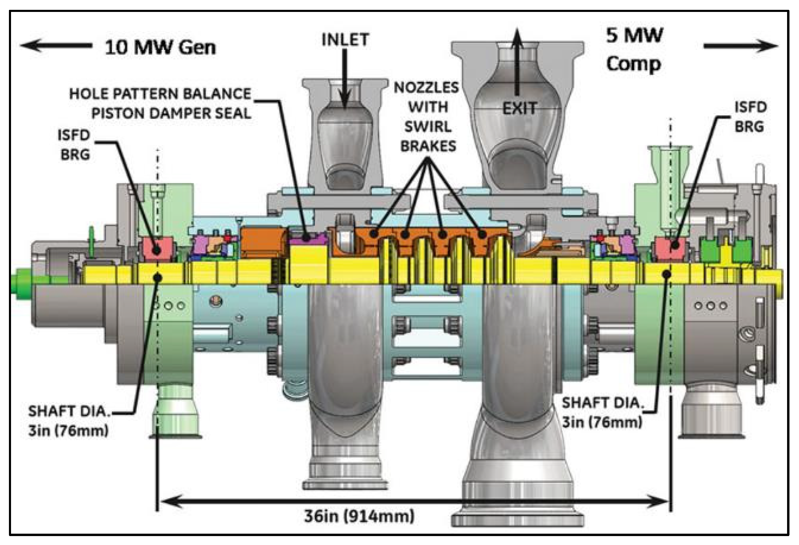
Figure 19 shows another concept of a 10 MW sCO
2 turbine that has been developed by the SwRI and GE, also under DOE’s Sunshot Program [
56].
It is an axial, four-stage machine that has successfully generated 15 MW gross power at 715 °C-250 bar (inlet conditions).
Here, the shaft diameter is very thin (76 mm) and the blade heights are very small and also virtually constant along the four stages; the axial length occupied by the four turbine stages is also very small (approximately 250 mm).
This brief overview of two intermediate sCO2 turbomachinery prototypes clearly illustrates the disruptive conceptions involved in sCO2 turbomachinery developments and the imaginative designs developed by engineers.
7.2. Likely Critical Design Points and Technology Locks
It is now interesting to try to identify and summarize the most important technical challenges underlying these developments.
7.2.1. Metrological Difficulties
First of all, the development of sCO
2 cycles poses a very specific metrological issue due to the fact that, in the vicinity of the saturation curve and more particularly of the critical point, it becomes difficult to carry out, with adequate accuracy, the physical measurements needed during the engineering tests to determine prototype performances [
57]. This comes from strong variations in density, Cp and speed of sound in this specific region of the P-T diagram; the speed of sound is important in high-speed flows of turbomachines because it determines local Mach numbers.
7.2.2. Rotor Dynamic Stability of Turbomachines
The mechanical design of turbomachines must take into account, from a dynamic point of view, an important specificity of critical fluids, namely their high densities and little compressibility which impacts on critical speed and vibration levels. Fast load variations are conducive to steep torque variations of the turbine rotor. This both increases radial imbalances on it and generates strong accelerations/decelerations of its rotation due to its small mechanical inertia; this also causes strong axial thrusts [
56]. Hydraulic turbines use also a dense fluid (water); however, the inertia of their rotor is much greater and the water flow is cold and virtually isothermal (no thermal stresses). In addition, they operate in open cycle mode, unlike the
closed nature of RCBCs in which a change in state of one component (e.g., the turbine) results in retroactions from others, with the possibility of cascading effects and even resonance events.
Changes in regime, whether programmed or unplanned (trips of the unit), must therefore be anticipated during design and carefully analyzed and controlled.
7.2.3. Strong Pressure Gradients and Variations during Transient Regimes
Likewise, it is necessary that all components feature mechanical resistance adapted to the pressure variations (over time) and the gradients (between the P- and P+ cycle branches) which prevail during starts, load variations, stops and trips that may occur from full load. Indeed, these transient effects, similar to “water hammers”, may generate intense and sudden pressure differences between the “P+” and “P-” branches of several components; this is of special concern in heat exchangers which must have therefore adequate material over-thickness.
7.2.4. High Thermal Gradients
In high temperature sCO
2 cycle applications, the expansion process creates by definition important thermal gradients along the turbine rotor [
54].
The point is that the short length of the latter means that these gradients concentrate on short axial sections of the shaft. The more localized expansion/contraction processes which result cause important mechanical stresses to the material and significant localized expansions/contractions which require cautious studies in terms of component “lifing” (thermal fatigue effects), with the need to select proper metal alloys.
7.2.5. Control of CO2 Leaks
Leaks of the working fluid are critical in any closed cycles and even more so when operating for long periods under high pressure, with the requirement of a very strict tightness [
58]. Conventional refrigerators and heat pumps operate also in close loop but they are less subject to this issue due to quite moderate pressures.
CO2 leak rates are magnified by the high operation pressures (up to 250 or even 300 bar) and the high recirculation rates due to the low values of the SPOs.
Yet it is essential to reduce leaks at turbomachine bearings to a strict minimum, for several reasons:
- -
to control and minimize CO2 consumption
- -
to reduce efficiency penalties (“CO2 that has leaked no longer works in the turbine”)
- -
to minimize health and safety risks (asphyxiation)
- -
finally, to quickly access the targeted stationary regimes, as CO2 leaks imply deviations in operating parameters (flow rates; pressures; temperatures).
In comparison, when a steam turbine leaks, the resulting H2O losses are environmentally benign and do not induce excessive additional costs on the site where this machine is installed, because there are generally adequate water resources on the spots. As far as GTs are concerned, air leaks (essentially at the compressor rear bearing when it exists) and combustion gas leaks (at the rear turbine bearing) are less critical because (i) the pressures are relatively modest (maximum 30 bar) and (ii) since air Brayton cycles are open, the leaks do not impact on the cycle fluid inventory; they are diluted by air venting and evacuated from the enclosure which surrounds the machine.
The case is different for sCO2 cycles because carbon dioxide is a manufactured product which must be purchased, transported and stored under pressure while complying with strict safety measures.
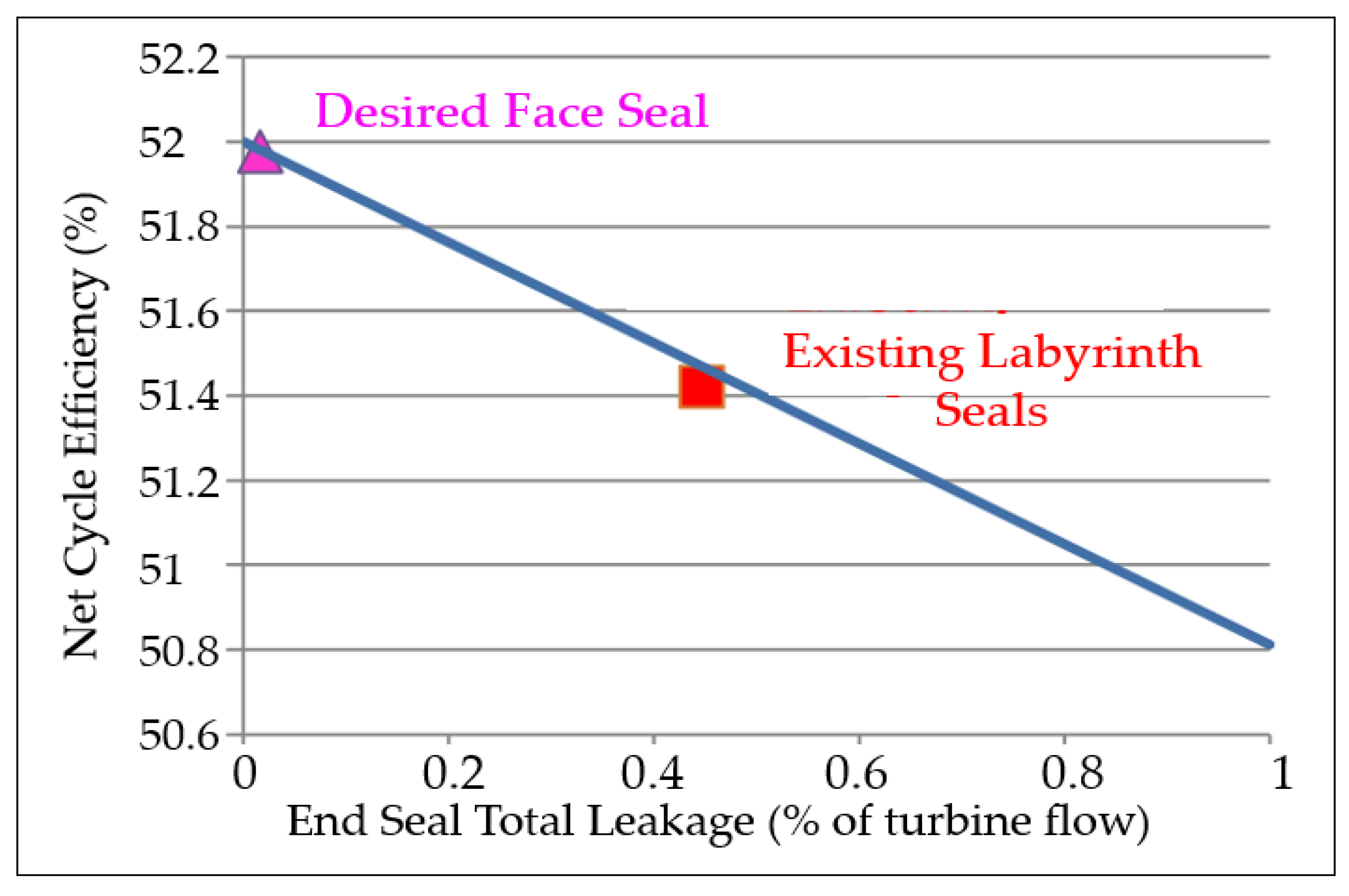
Figure 20 illustrates the engineering challenge posed by reducing leak rates at a suitable level under the STEP program [
58]. While, in current turbine technologies, leaks represent on average 0.4% of the passing flow rates, the objective to be achieved in sCO
2 closed cycles is a maximum leak rate of around 0.02% at turbine bearings.
It is therefore, ultimately, a question of achieving a very high degree of tightness, unprecedented in the history of turbomachines in power generation applications.
To achieve such an ambitious target, researchers have developed innovative sealing devices involving very specific designs, such as that based on the injection of “counter-flows” of CO
2 into turbine labyrinths [
59]. We easily realize the complexity added by these devices to solve a problem which had not even been envisaged by the inventors of the sCO
2 power path and the consequences in terms of design: “the devil is in the details! “...
The whole CO
2 storage and circuitry, called the “fluid inventory”, has then become an integral system item of the cycle [
60].
7.2.6. Turbomachinery Efficiency
The levels of isentropic efficiencies mentioned above for turbines et compressors are still modest and must/will be increased as development progresses. The point is that most advanced sCO2 Brayton cycles (RCBC) include two compressors and at least one turbine and even more in the case of multiple heat recovery, as set out in § 6.2. The overall electrical efficiency gets “eroded” when the number of turbomachines increases.
This is a major task to conduct in order to be able to cope with and exceed the performance of steam cycles not only in “ideal” conditions but also in real ones. This requires long and costly aerodynamic, thermal and mechanical studies [
61,
62].
8. Conclusions
Supercritical CO2 cycles offer a rare opportunity for significant efficiency gains in electric power generation, which would greatly benefit the energy transition. However, since its discovery in the late 1960s, the translation of this technology into real large power units seems slow to happen.
In that context, the main motivation of this article was to investigate the possible reasons for this unexpectedly long industrialization process.
Pursuing this goal required a dive into the science of sCO2 cycles, which led us to address the following aspects of that technology: (i) the classification and architectures of cycles, (ii) their thermodynamics and (iii) their conceptual advantages and drawbacks. To judge their actual merits, we were also led to compare their theoretical energy performances to those of conventional power generation paths.
Fundamentally, the technology has really a significant potential in terms of efficiency enhancement and reduction in component sizes. The efficiency comes from the favorable balance of compressions and expansions which is inherent to supercritical fluids. The advantage of reduced components size is tied to the high “energy density” of supercritical fluids compared to those of steam and air used in conventional Rankine and Brayton cycles, respectively.
The thermodynamic evaluation of the possible architectures carried out in our work confirms that the RCBC (Recompressed Closed Brayton Cycle) architecture is the most promising within the energy transition process, with an ideal efficiency reaching 48% as soon as the heat source attains 550 °C, rivaling thus with most modern gas turbines fired at 1400–1500 °C.
The turbomachine prototypes resulting from the development programs carried out to date confirm the significant gain in component size; this is despite the low specific power outputs (SPO) of the cycles which result from the necessarily low pressure ratios.
In addition, the number of auxiliary components will be considerably reduced compared to steam Rankine units which need a complex set of auxiliaries. In other words, the complexity and footprint of the balance of plant (BOP) will be reduced, which will have favorable impacts on CAPEX and O&M expenditures [
63].
The need for intense heat recuperation to compensate for the low specific outputs is no longer an obstacle thanks to the availability of very compact and efficient heat exchangers, notably those of the PCHE technology [
64].
However, improving efficiency is probably the “mother of battles” that engineers must win in the next development cycles if we want sCO2 cycles to be highly efficient and become instrumental in the energy transition. Indeed, the actual energy performances of Brayton sCO2 cycles strongly depend on the isentropic efficiencies of the set of turbomachines they need for their operation, which comprises at least two compressors and one turbine. These machines have strong operational specificities and their development faces multiple and unprecedented technical challenges, namely (i) to ensure the rotational stability of the composite shaft, (ii) to cope with the strong pressure variations (over time) and gradients (between circuit branches), (iii) to bring the level of leaks at turbine bearings to an unprecedentedly low level despite the high pressures and, especially, (iv) to improve the isentropic efficiencies of the compressors and the turbine.
The validation and improvement of turbomachine technology therefore seems to be the stumbling block for the success of that technology and its deployment in large power generation blocks.


