Article

A New Approach to Use of Traction Power Network in Poland for Charging Electric Vehicles

by
Łukasz Mazur
*,
Kazimierz Stanisław Bieliński
and
Zbigniew Kłosowski
Institute of Electrical Engineering, Faculty of Telecommunications, Computer Science and Electrical Engineering, Bydgoszcz University of Science and Technology, 85-796 Bydgoszcz, Poland
*
Author to whom correspondence should be addressed.
Energies 2024, 17(5), 1123; https://doi.org/10.3390/en17051123
Submission received: 13 December 2023 / Revised: 12 February 2024 / Accepted: 23 February 2024 / Published: 27 February 2024
(This article belongs to the Section E: Electric Vehicles)

Abstract

:
Electric vehicles are increasingly appearing on Polish roads due to a number of technical, legal and marketing conditions. However, electromobility is developing primarily in urban areas, mainly due to the unevenly developed infrastructure for charging vehicle batteries and the power grid. Therefore, solutions should be created that use the existing power infrastructure, including the use of railway power infrastructure (RPI). The railway power network covers a significant part of the country, including forest areas, and, above all, it very often intersects with road infrastructure or runs along roads. This paper raises issues related to the possibility of using RPI to charge the batteries of electric vehicles. After characterizing the technical, operational and legal requirements related to these technical systems, a concept of an electric vehicle charging system using RPI was developed, along with a demonstration of the possibility of its implementation, which was simulated using mathematical models developed by the authors.

1. Introduction

Electromobility is an important and topical issue, often discussed by experts in the field of energy, transport, economics and environmental protection. There is a growing trend in the use of electric vehicles (EV) around the world. The development of this interdisciplinary field of science and technology is possible thanks to intensively conducted scientific and research projects, social programs and marketing activities that have led to the popularization of electromobility and the increased efficiency of electric vehicles themselves, as well as the entire technical infrastructure related to the charging of built-in electric energy storage facilities in vehicles [1,2,3,4,5]. An important research aspect is to learn about the impact of the development of electromobility on changes in the functioning, structure and management of local power systems that are elements of the National Power System (in Poland—Krajowy System Elektroenergetyczny) [6,7].
There are more and more battery electric vehicles (BEVs) on the roads, and their range is systematically increasing. However, without a properly planned and deployed technical infrastructure ensuring the supply of electricity in the required quantity and acceptable time to each vehicle (energy storage), electromobility will not be able to develop further dynamically. Therefore, it is not an exaggeration to say that the availability of charging infrastructure for electric vehicle batteries in the country or region will stimulate the development of electromobility in this area. Various charging systems for electric vehicles are available. The most commonly used are wired charging systems (described in detail in the standards published by the International Electrotechnical Commission—IEC 61851 [8] and IEC 62196 [9]), wireless [10] and charging systems by replacing batteries, the so-called battery swap [11].
Currently, electromobility in Poland is developing mainly in urban areas, which is caused, firstly, by the greater wealth of city residents and the larger number of electric vehicles in their area, and secondly, by the uneven distribution of infrastructure for charging batteries of electric vehicles in the country [5]. The distribution of charging infrastructure is also influenced by the unevenly developed power grid in Poland.
Stations and charging points for electric vehicles can be built, for example, at gas stations, which most often requires a new connection to the power grid, but in Poland, the investment implementation time may take up to two years [12]. That is why it is so important to create and implement solutions that allow for the effective use of the existing power infrastructure [13,14]. In this regard, a great opportunity for the development of electromobility may be the use of RPI. The traction power network supplying railway traction covers a large part of the country, including forest areas, and, above all, it very often intersects with road infrastructure or runs along roads. Due to the appearance of an increasing number of vehicles with an EV or plug-in hybrid drive on Polish roads, the railway electricity infrastructure is becoming a serious alternative to the solution of standard power supply systems for charging stations, especially in sparsely populated areas, away from dense buildings. This may increase interest in electromobility also in rural areas. Railway traction networks, together with electricity storage facilities, can constitute integrated charging systems, significantly increasing the energy efficiency of the entire traction network power supply system—usually, electrical energy from braking trains is lost to heat on braking resistors, and it can be used to charge EVs.
The aim of this paper is to propose the concept of a charging system for electric vehicles cooperating with the existing railway power infrastructure, indicating the areas of application and assessing the feasibility of their implementation, while minimizing the construction of new components, yet also ensuring the implementation of their basic tasks. The expected solution is intended to shorten the investment time in new EV charging stations in Poland, which would allow for faster fulfillment of the demands contained in the Act on Electromobility and Alternative Fuels regarding the number of EV charging points [15]. Electromobility using railway electricity infrastructure provides an opportunity for an innovative approach to the National Power System in Poland (NPS) in the field of designing smart grids. The achievement of the goal will be possible thanks to the development of a mathematical model of the adopted concept, conducting simulation tests and assessing the impact of the adopted solution on the environment, electric vehicles, the power grid and the railway infrastructure.
The research problem was formulated as a question: What technical conditions, design features and electrical parameters of electrical systems coupled with the railway power infrastructure (RPI) are necessary for the construction of electric vehicle charging systems in Poland?
This paper consists of six sections. The first chapter contains an introduction to the issues discussed in the manuscript. This chapter formulates the purpose of the paper and specifies detailed tasks to achieve these goals. The second section presents information on RPI. This section characterizes the electrical power railway infrastructure used in Poland. Then, after reviewing national and global literature, a review of technical solutions and concepts that use the electric traction network (rail, tram, trolleybus, metro) to power electric vehicle charging points was created. The third section describes the general assumptions and postulated conditions for an electric vehicle charging system using RPI. The key part of this section is a description of the concept of using RPI for EV charging created by the authors. The fourth section concerns materials and methods of analysis. It presents a situational diagram of the solution, taking into account all relationships occurring in the system. The process of creating mathematical models of all the subsystems creating the analyzed solution was presented in detail. The last part of the section describes the created simulation program and presents the research program and plan. The fifth section presents the results obtained from simulations using mathematical models and an analysis of the energy and ecological efficiency of the adopted solution based on selected efficiency indicators. An attempt was also made to determine the efficiency of energy conversion in a battery-charging system of electric vehicles using electricity obtained from train braking. Section six is a summary of the paper. It contains the main conclusions and observations and formulates guidelines for further research directions in the use of RPI for the development of electromobility.

2. Review of Technical Solutions for Charging Electric Vehicles Using Railway Power Infrastructure

RPI is an important element of the power system of every country, including Poland [16]. The Polish railway network is over 12,000 km long (63% of all railway lines) and includes over 800 traction substations and over 6200 power stations. The system of supplying the railway traction network with direct current with a rated voltage of 3 kV in Poland does not allow full use of the potential resulting from the possibility of recovering electrical energy from the regenerative braking of electric multiple units, due to the use of unidirectional power electronic converters in traction substations, which prevent this energy from being fed back to the system. Distribution system operators (DSOs), to which traction substations are connected, are not interested in purchasing electricity generated in an unpredictable manner, and this energy is used either by another vehicle currently traveling on the same track or is lost to heat in braking resistors located on the same track. [17]. However, there are solutions, with mobile energy storage tanks storing this energy.
The use of railway power infrastructure to charge electric vehicles is not a frequently used solution. However, there are several technical solutions regarding charging, power supply and the intercorrelation of electric vehicles with electric traction networks (mainly with urban traction networks powering trams, metro and trolleybuses) [1,12,13,14,18,19,20,21,22,23,24,25,26].
The use of the urban traction network to power electric buses brings many benefits, including minimizing costs related to the construction of lines supplying charging points from the distribution power grid. Moreover, the construction of such a line is not always possible due to the technical transmission capabilities of the given section to which the station is to be connected. Examples of such a solution are presented in [1], which concerns the direct charging of electric buses using a pantograph with the voltage from the city traction network VN = 600 V DC (directly from the network or through a power electronic DC/DC separation converter).
Another interesting implementation of a system for powering electric buses from the urban traction network is the “Slide-In” project presented in the literature [12]. It concerns the use of the trolleybus traction network to charge the batteries of electric vehicles while driving. For example, an electric bus or trolleybus with an energy storage tank, in the absence of stored electricity, can be recharged from the city traction network using a pantograph—both while driving and when standing still. However, this system assumes that the main source of energy necessary to move the vehicle is the battery. The use of batteries means that trolleybuses can operate on non-electrified sections of the route. An example of such a solution can also be found in Krakow—the pantograph charger of an electric bus is connected to the tram traction network through a DC/DC separation converter [13]. The arm with the protection system is located on one pole, and the converter on the other.
The traction power network can also be used to power electric car chargers. The system presented in article [14] describes the cooperation of electric vehicle charging stations with the traction power network supplying metro lines. Electric energy storage is connected to the traction network circuit via a traction power supply in order to store the recuperative energy obtained as a result of the electric braking of rail vehicles [14].
A very interesting solution was proposed in the article by the researchers of [18] where connection to an overhead traction line would allow the use of energy from regenerative braking. A feasibility analysis was carried out for a trolleybus traction power supply system in the Polish city of Gdynia, which confirmed the validity and advantages of such a solution.
A similar solution for using RPI to charge EV batteries is presented in article [19]. It concerns charging electric vehicles at railway stations with electricity from renewable energy sources and from regenerative braking from the traction power network. The charging system, using appropriate converter systems, is powered by a 750 V DC bus from the MV distribution network, 0.4 kV LV network, 3 kV DC railway network and photovoltaic installations. Chargers are connected to the bus. Due to the unpredictable process of generating electricity from renewable energy sources and regenerative braking, energy storage systems are also connected to this network.
The example described in the literature [20] presents the concept of a system for charging the batteries of an electric vehicle powered by the traction network powering the metro in Rome. The main assumption, as in the case of other solutions of this type, is to increase energy efficiency by using the energy obtained from regenerative braking. Vehicles can be charged using classic wired chargers or by “battery swap”. In order to increase reliability, the proposed charging system is powered from the distribution network and uses a bidirectional V2G energy flow interface.
A similar solution was presented in publication [21]. The proposal involves the creation of a smart DC microgrid (in this case, it is a network with a rated voltage of 900 V), which is powered by the railway traction power network and the LV distribution network. Chargers for electric cars, high-power chargers powering electric buses using the pantograph, and energy storage units designed to collect braking energy are connected to the DC power grid.
Electric vehicle charging stations are increasingly located at railway stations. The example from publication [22] presents the concept of an intelligent system for charging electric vehicles located in parking lots at railway stations, and the main goal of this solution is for owners of electric cars not to commute to work by their own means of transport but to choose rail transport. An electric vehicle left at a charging station would be charged while the vehicle owner was at work. Moreover, the proposed concept also uses EVs as energy storage and implements the assumptions of the V2G system based on extensive energy management algorithms. In the context of the development of EV charging systems and the related V2G technology, the use of renewable energy sources is combined. In paper [23], the authors developed an algorithm for selecting the power of a photovoltaic system for charging the traction batteries of an EV, using the Metalog distribution to simulate various strategies for generating electricity by photovoltaic systems.
A way to increase the efficiency of rail transport and better use regenerative braking energy is to optimize the timetable and driving strategy of all vehicles traveling on a given route section [24]. A similar solution is described in [25].
The development of electromobility in the context of covering longer distances was dealt with by the author of publication [26]. The author developed a model simulating a journey, taking into account arrival and entry to the charging station based on real traffic data, to determine the required number of charging stations. The scenarios took into account, among other things, peak demand. Based on the analyses, the appropriate number of stations was determined to achieve the set goal: to charge from 10% to 20% of all passing cars.
There are no implemented solutions that directly use RPI for EV charging, but after familiarizing ourselves with the structure of RPI and the proposals presented in the literature [12,13,14,15,16,17,18,19,20,21,22,23,24,25,26], it can be concluded that it is technically possible to use RPI for the development of electromobility.

3. Description of the Developed Concept

When designing electric vehicle charging systems using RPI in Poland, all legal regulation [15,27,28,29,30] restrictions contained in standards [8,9,31], and the conditions of the environment in which these systems will operate, should be taken into account. This is necessary information to formulate design assumptions. Figure 1 shows a diagram of the relationship between each technical system (ST) operating in the environment (O), with the border zone (SG) and monitoring zone marked between them.
When creating the above ST, recognizing its independent and dependent variables, disturbances, constant values and determining limitations, it is necessary to define the postulated states (SP), which can be described by the following Equation (1) [32,33]
S P e ,   η ,   q ,   D ¯ = f K ,   N ,   E ,   L ,   s ,   z ,   t ,   θ
where e—effectiveness of the EV battery-charging process using energy storage, η—efficiency of energy conversion, energy converters, q—quality of the elements, materials and raw materials from which the system is made, D - —harmlessness of the system to the surroundings, environment and humans, K—benefits (economic, ecological, energy), N—inputs (economic, ecological, energy), E—input and output energy, L—useful work, s—control, z—disturbances, t—time, θ—life cycle.
The following postulated states of the electric vehicle battery-charging system using RPI were defined:
  • Popularizing electromobility by increasing the number of points and stations for charging electric vehicles using RPI;
  • Achieving high energy efficiency of electric vehicle charging systems by using the potential of RPI;
  • Achieving high ecological efficiency by reducing CO2 and dust emissions into the environment;
  • Recovering as much electricity as possible from regenerative braking of the train and using it to charge the lithium-ion batteries of electric vehicles.
The concept developed by the authors uses the business model of “car-sharing” companies, which offer services in the field of the shared use of electric cars, whose main logistics and energy management centers are located at railway stations. The concept concerns the creation of a mobile station for charging and replacing electric vehicle batteries, which will be located on a special platform attached to the train. The main element of the platform will be a battery-charging station built in the form of shelves, on which the previously discharged batteries of electric vehicles will be placed and recharged. The battery-charging and replacement points will be powered by the traction network (3 kV DC) via a pantograph, with priority being given to the energy recovered from the train braking process. The platform will be equipped with an energy storage unit with a charging controller, which will be used to collect energy obtained during regenerative braking. Due to the dynamics of the process and the large amount of energy that can be stored during regenerative braking in a relatively short time, the best energy storage solution is a supercapacitor. The system also requires the use of a DC/DC converter system to adjust the EV battery-charging parameters. Figure 2 shows the solution diagram.
As mentioned, the logistics centers of these systems will be located at railway stations, and a warehouse for discharged and charged batteries will be located there. After arriving at the destination or intermediate station of a train with a mobile battery-charging system, the platform is detached from the train and taken to a railway siding, where the charged batteries are unloaded from the platform and, after unloading, they are returned to the charged battery storage room and the discharged batteries are loaded onto the platform. At the same time, when the train is scheduled to depart to the next station, another platform may be attached to this train with batteries previously placed on it to be charged.
Electric vehicles owned by a car-sharing company will be directed (thanks to an extensive IT system) to the logistics headquarters, where the process of replacing the discharged battery with a fully charged battery will take place. The car is parked on a lift located near the battery warehouse. This is where the batteries are replaced.

4. Materials and Methods

The analysis of the developed electric vehicle charging system using RPI requires the use of a research method that will enable a sufficiently accurate prediction of the system both in normal operation states and during disturbances. A system analysis was selected, which involves examining the processes, relationships and interactions occurring within it using mathematical models that represent interesting properties of the EV charging system using RPI and enable prediction of the system’s behavior by solving a specific class of mathematical problems [34].
To create a mathematical model, it is necessary to determine the range of independent quantities x, dependent quantities y, disturbances z and constant quantities c, which leads to the definition of a mathematical model of the technical system in a general form, which is presented in Equation (2) [33]:
F S T = f ( x 1 ,   x 2 ,   ,   x i ,   y 1 ,   y 2 ,   ,   y i ,   z 1 ,   z 2 ,   ,   z i ,   c 1 ,   c 2 ,   ,   c i )
Creating a mathematical model of the EV charging system using RPI is a complex process—to achieve the intended results, mathematical models of other subsystems included in the EV charging system must be created successively. Figure 3 shows a schematic presentation of the analyzed EV charging system using RPI, showing the mutual interactions and relationships between the subsystems.
The symbols presented in the above diagram refer to the following relations:
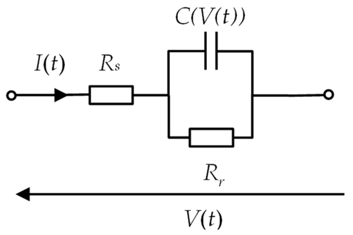
  • Independent variables: xtr—traction characteristics F = f(v) (dependence of the tractive force F on the speed v), xpoj—technical data of the vehicle, xrl—technical data of the route, xEST—data on the electric traction network, Rs—equivalent resistance of the supercapacitor module, C(V(t))—capacity of the supercapacitor, V0—initial voltage of the supercapacitor module, Pbatt—charging power of Li-Ion batteries (discharging supercapacitors);
  • Dependent variables: V(t)—course of changes in voltage at the pantograph, i(t)—course of changes in the intensity of current absorbed/remitted by the vehicle, p(t)—course of changes in power consumed and generated by the traction vehicle, e(t)—course of changes in electrical energy over time, Vsc—voltage of the supercapacitor module, isc—charging current of electric vehicle batteries, SoCsc—degree of charge of the supercapacitor module;
  • Disturbances: zi—local terrain slope, zh—sudden braking, zt—local speed restrictions caused by maintenance work or breakdown;
  • Constant values: T—temperature, κ—coefficient of the influence of voltage on the capacity of the supercapacitor.

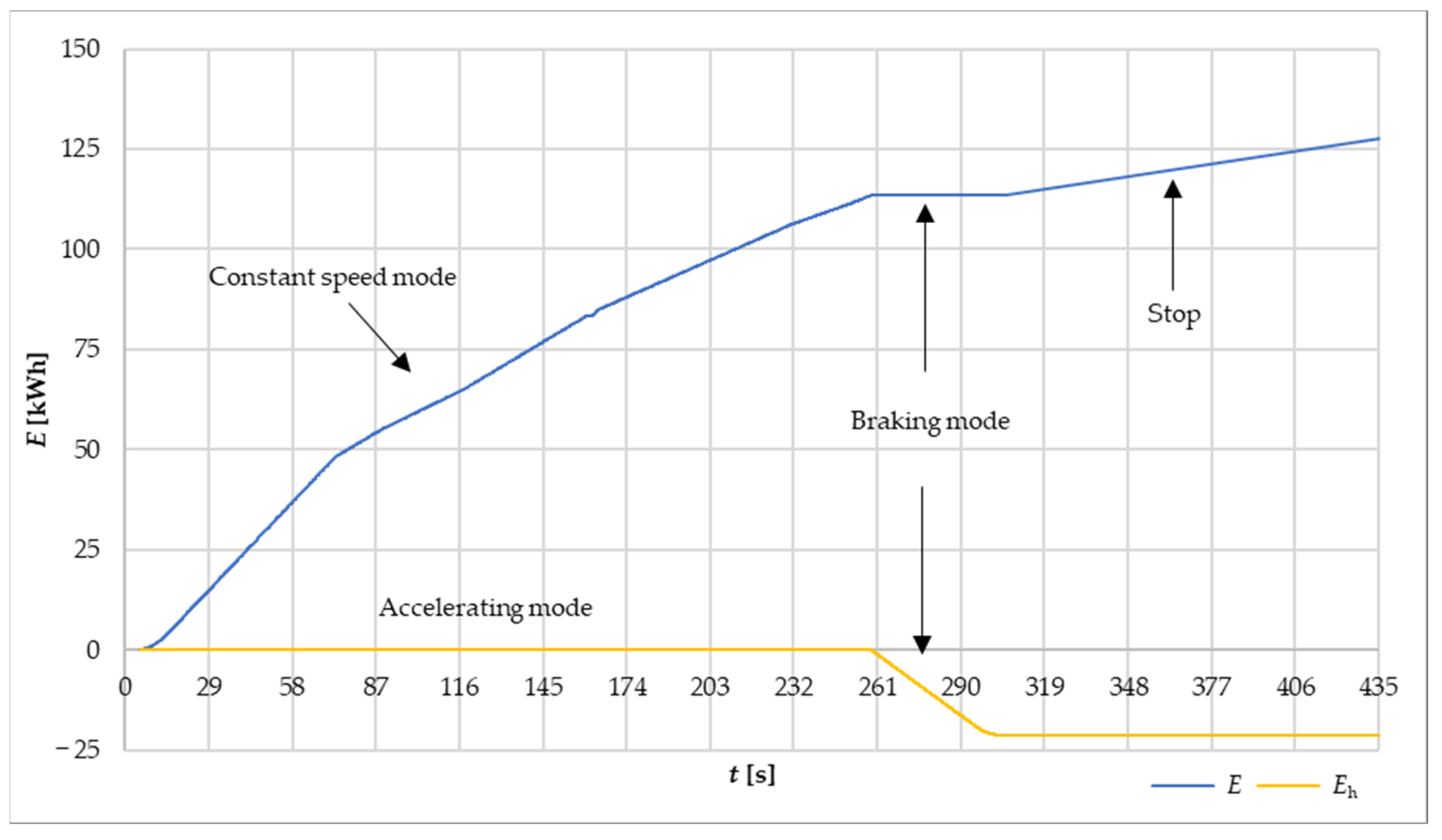
4.1. Modeling of the Theoretical Journey

As can be seen in Figure 3, the first part of the mathematical model concerns the journey of a theoretical rail vehicle, the method and methodology of which is widely known and described in detail, among others in [15,35,36,37,38,39]. Based on input data regarding the type of vehicle and its traction characteristics, understood as the change in tractive force as a function of speed changes F = f(v), and data on the route and the traction power network, using the classical equation of motion in accordance with Newton’s second law of dynamics, you can receive information about the distance traveled, the power consumption of the vehicle, the load on the power supply system, the vehicle current understood as the current consumed by the vehicle for traction purposes and its own needs, and the charging current of the energy storage tank obtained from braking the vehicle [35,37]. The equation of motion of the vehicle can be written as follows (3)
a = d v d t = F p m · k = F ( v ) W ( v , s ) m · k
where a—vehicle acceleration, m/s2; v—vehicle speed, m/s; t—time, s; Fp—accelerating force, N; m—vehicle mass, kg; W(v,s)—accelerating force, which is the difference between the tractive force Fp and the movement resistances W, N; k—inertia coefficient of rotating masses representing the kinetic energy of rotating masses (engine, gear, wheels, etc.): e.g., for traction units k = 1.15 [35].
This will allow you to determine the energy consumption of the vehicle and, more importantly in the analyzed case, the amount of electricity generated during regenerative braking, which can be stored in the energy storage. Figure 4 shows a diagram of relations and dependencies related to the mathematical model of the theoretical journey of an electric traction vehicle.
The next part of the mathematical model of the EV charging system using RPI concerns the modeling of the process of charging an energy storage device—a supercapacitor. To model the charging of appropriate electric vehicle batteries using supercapacitors, a simulation of discharging supercapacitor energy storage with constant power will be performed.

4.2. Modeling of Movement Resistance

When carrying out a theoretical journey in accordance with Equation (3), it is necessary to take into account the basic resistance to motion W, which is a representation of the forces that act on the vehicle in motion, and these forces are not generated by the drive system [38,40]. There are three basic types of resistance to movement:
  • Basic resistance Wz related to rolling resistance, aerodynamic resistance, internal friction forces, which are approximated by a second-degree polynomial; e.g., in Poland, the formula developed by the Central Center for Research and Development of Railway Technology is used, which was written using Equation (4):
W z = 0.9 + 0.15 · 3.6 · v 10 · m + 15 · n o + n w + 2.7 · 3.6 · v 2 100 · g
where Wz—basic resistance, N; v—speed, m/s; m—vehicle mass, Mg (ton); no—number of vehicle axles; nw—number of wagons; g—acceleration due to gravity, m/s2;
  • Local resistance Wi, related to the resistance of the hill, determined using Equation (5):
    W i = Q · i
where Q—vehicle weight, kN; i—route slope, ‰;
  • Curve resistances Wr, which result from the forces acting on the vehicle while driving a curved road section and are determined using the so-called Röckel formula (6):
    W r = 6867 r
where r—radius of the arc, m.
The basic resistances W are the sum of the above resistances:
W = W z + W i + W r

4.3. Modeling of Traction Power System

For the analyzes related to the modeling of the traction power system, a double-sided power supply system was adopted, consisting of two identical traction substations, the upper traction network (the so-called contact network) with a unit resistance rsj, the lower–return network, which consists of railway rails with a unit resistance rsp, and electrical energy receivers–traction vehicles, modeled as a power source i(t). Each traction substation is powered by a voltage source Vo with internal resistance RPT. The equivalent electrical diagram of the model is presented in Figure 5.
The voltage on the pantograph varies during time t and depends on the distance s traveled, or more precisely, on the equivalent resistance depending on the current position of the rail vehicle R(s), and can be written using the following equation:
V s , t = V 0 R s · i ( t )
where V(s,t)—voltage on the pantograph, V; V0—voltage of the source, V; R(s)—equivalent resistance depending on the current position of the rail vehicle, Ω; i(t)—current consumed by a rail vehicle, A.
Knowing the traction characteristics of the train, based on the tractive force F(v) for a given speed v(t) and the voltage on the pantograph V(s,t), using the following equation, it is possible to determine the current consumed by the rail vehicle for traction purposes:
i ( t ) = F ( v ) · v ( t ) V ( s , t )
where F(v)—tractive force, N; V(s,t)—voltage on the pantograph, V.

4.4. Modeling of Supercapacitor

The mathematical model of the supercapacitor was created based on the equivalent diagram shown in Figure 6.
The capacity of the supercapacitor C(V(t)) depends on the voltage V(t) and can be described by the following equation [42]:
C V t = C 0 + κ V t
where C0—capacity of the supercapacitor in the voltage-free state, F; κ—coefficient describing the influence of voltage V(t) on the capacity of the supercapacitor (given as catalog data), F/V [42].
The series resistance Rs in the model is responsible for power losses during the flow of current I(t). This value is given as catalog data for a single cell. In turn, the parallel resistance Rr represents the process of self-discharge of the supercapacitor [43].
The state of charge of a supercapacitor SoCsc is determined as follows using the Equation [44]:
S o C s c = ( V t ) 2 V m a x 2
where Vmax—maximum voltage of the supercapacitor, V.
The energy stored in the supercapacitor is calculated according to the formula [45]:
E s c = C ( V t ) · ( V t ) 2 2
where Esc—energy stored in the supercapacitor, J.
In the developed model, the lithium-ion battery, the DC/DC converter and the microprocessor system regulating the charging process will be simulated indirectly. Charging the lithium-ion batteries on the train will be modeled as loading the supercapacitor tank with constant power consumption.

4.5. Research Plan

The aim of the first part of the study is to simulate the journey of a theoretical traction vehicle that moves on a railway line with a vertical profile shown in Figure 7.
It is assumed that the examined railway route is a straight section with no bends, which does not take into account the local traffic resistance Wr related to curves.
The maximum train speed on the entire section is vmax = 110 km/h. The study assumed an idealized case in which emergency braking does not occur.
There are four stops on the examined route section (station A—0.000 km of the route, station B—7.821 km of the route, station C—15.973 km of the route, station D—26.088 km of the route).
The section of the analyzed route is powered by two PK-17/3.3 traction substations located at the beginning of the analyzed section (0.000 km) and at its end (26.088 km). Data regarding the PK-17/3.3 substation are presented in Table 1.
The upper traction network (contact network) is a 2C120-2C-1-type network with a cross-sectional area of 440 mm2 and a unit resistance of rsj = 0.045 Ω/km [35]. The return network is a one-track bus network made of a UIC60 bus, the specific resistance of which is rsp = 0.0166 Ω/km [35].
The theoretical journey will be performed for an electric multiple unit (EMU) EZT 31 WE powered by voltage VN = 3300 V DC, with continuous power p = 2.0 MW, total gross weight mp = 172 t, starting acceleration a = 1 m/s2 and maximum speed vmax = 160 km/h (44.4 m/s). EZT 31 WE is a rail vehicle consisting of four units. The base speed is vb = 36.4 km/h (10.1 m/s), and its traction characteristics are described by the Formula (13):
( v ) =   197.8   ·   10 3           dla       0 v 10.1   m s   2   ·   10 6 v                             dla   10.1 < v 44.4   m s
It was also assumed that the maximum auxiliary power does not exceed 400 kW and the efficiency of the drive system is η = 0.85.
Another goal of the research is to learn about the charging and discharging characteristics of the supercapacitor energy storage device and to estimate the amount of electrical energy that can be recovered and stored in the energy storage device.
To store energy from regenerative braking, the BMOD0063 P125 B04 supercapacitor module was selected, the basic parameters of which are presented in Table 2.
Due to the voltage-matching of the supercapacitor energy storage to the traction network, the model assumes the use of 135 modules (27 modules connected in series in five branches). The nominal capacitance of such a connection is CN = 11.67 F at nominal voltage VN = 3375 V.
In a simulation study, an electric vehicle battery-charging station built in the form of shelves located on a train has the ability to simultaneously charge 10 lithium-ion batteries. It was assumed that during the simulation, the train contains 8 lithium-ion batteries with a voltage of V = 360 V, capable of storing a nominal 24 kWh of electricity. The charge level of each battery was assumed to be SoCbatt = 10%. Each lithium-ion battery can absorb 13.5 kWh of electricity at this level of charge. This means that 108 kWh of electricity is needed to fully charge these batteries.
The energy storage tanks are charged while the EMU is braking. In the model, each braking lasts 46.4 s, on the road sh = 839.21 m. In the simulation, three brakings take place at the following travel times:
  • Charging I: 255.6 s–302.0 s of simulation;
  • Charging II: 696.8 s–743.2 s of simulation;
  • Charging III: 1207.3 s–1253.7 s of simulation.
The research assumes that the charging process of lithium-ion EV batteries, simulated as discharging the supercapacitor module with constant power consumption, is controlled by the BMS (Battery Management System), which is responsible for the uniform charging of each battery. Discharge of the supercapacitors with constant power equal to Pbatt = 150 kW, simulating the charging of Li-Ion batteries, takes place in the time between the end of one braking and the beginning of the next one. The test will involve three discharges of supercapacitors between charging I and charging II, between charging II and charging III and after charging III:
  • Discharge I: 302.1 s–696.7 s of simulation, duration tr = 394.6 s;
  • Discharge II: 743.3 s–1207.2 s of simulation, duration tr = 463.9 s;
  • Discharge III: 1253.7 s–1653.7 s of simulation, duration tr = 400.0 s.
For the first cycle, it was assumed that the initial voltage of the supercapacitor storage tank is V0 = 830 V and the degree of charge SoCsc = 5.0%.
The logistics center and all technical infrastructure related to the replacement of electric vehicle batteries are located at the starting station—the simulation does not envisage removing the batteries at the final station. At the end, the direction of the train is changed from the end station to the start station using a turntable. This process ends with a simulation study.
A simulation study was performed to verify the adopted solution created using the mathematical models described in the paper. Matlab R2022b Simulink software was chosen as the simulation tool, with a mathematical model of theoretical transfer and a model of charging and discharging supercapacitors with constant power in the Simulink environment, and an MS Excel spreadsheet was used to present the results.
Based on the results obtained, an energy and ecological assessment of the solution was performed based on the following efficiency indicators:
  • Efficiency of electrical energy recovery from regenerative braking;
  • The degree of coverage of electric energy obtained from braking the train for the purpose of charging electric vehicle batteries;
  • Efficiency of the process of recovering electricity from train braking for the purpose of charging EV batteries;
  • Ecological benefits due to the reduction of pollutant emissions.

5. Results

5.1. Simulation Results of the Theoretical Journey

The results of the theoretical journey for the analyzed research case are presented in detail below. Figure 8 shows the course of changes in speed, distance traveled and tractive force for the simulation study. The main phases of train motion marked in Figure 8a for the first full cycle (starting, running at constant speed, braking, stopping) are repeatable for subsequent cycles, and the difference in their duration results from disturbances introduced into the model in the form of local movement resistances or the occurrence of coasting.
The course of changes in electrical quantities (current, voltage on the pantograph, active power and electric energy) are shown in Figure 9.
The shape of the obtained waveforms of tractive force and acceleration coincide with the theoretical waveforms described in the literature [15,35,37]. The computational algorithm responds correctly to the introduced disturbances. This allows us to state that the created mathematical model is correct.
The waveforms of the resulting electrical quantities, which are a continuation of the traction calculations, also seem correct. In Figure 9c, showing the course of voltage changes on the pantograph, it can be seen that the voltage does not exceed the rated voltage of the traction substation, even in the case of braking and electricity generation—at this stage of mathematical modeling, it was assumed that the energy of regenerative braking covers the own needs of the electric multiple unit and that the supercapacitor energy storage tank is able to store the remaining energy obtained during recuperation. If the storage device is unable to store energy, in a real case, the electric voltage in the traction network would increase, the excess electric energy would be taken by another vehicle traveling on a given section, and in the absence of collection, the energy would be lost on the braking resistors—at the beginning. The study assumed that only one train moves on the track while traveling, so the excess energy that cannot be stored in the energy storage tank will be lost in the resistors.
To show in detail the flow of electrical energy in each phase of vehicle movement, Figure 10 shows the consumption and generation of electrical energy during the first driving cycle of the EMU from station A to station B, with the phases of movement marked.
Analyzing the above figure, it can be noticed that the largest increase in energy consumption occurs in the train start-up phase (high starting currents of electric motors, the need to overcome movement resistance). When driving at a constant speed, the vehicle uses much less electricity for traction purposes. Moreover, it turns out that the non-traction needs of this train are relatively large, which is especially visible when the EMU stops at the station. The figure shows that the vehicle generates electrical energy during braking, which is stored in a supercapacitor energy storage device and covers the non-traction needs of the train. On the tested section of the electric traction network for the EMU, it was determined that during one braking, Eh = 21.3 kWh of electricity can be theoretically generated, which can be stored in a supercapacitor. The created model assumes that each braking takes place in the same conditions, i.e., it starts from a speed of vmax = 110 km/h to v = 0 km/h, and the given section of the route on which braking takes place is flat. This means that the amount of electrical energy that can be obtained is identical during each braking process. However, taking into account the efficiency of the supercapacitor at the level of 97.0% [47], and the efficiency of the power electronic converter at the level of 95.0%, gives the efficiency of the supercapacitor storage system at a level of 92.2%. From one braking, taking into account the efficiency of the supercapacitor storage system, Eh = 19.6 kWh of electrical energy can be recovered Therefore, for the three EMU braking models modeled in the study, ∑Eh = 58,8 kWh of electrical energy can theoretically be recovered. Figure 11 shows the waveforms of voltage and SoCsc for the capacitor module for all analyzed research variants.
During the first braking, the supercapacitor modules were sufficiently discharged and could absorb all the electrical energy obtained from braking. The charge level after braking was SoCsc = 93.4%. The first charging of EV batteries (discharge of supercapacitors) with a power of Pbatt = 150 kW resulted in the discharge of the tank to the level of SoCsc = 18.5%. Such a high degree of charge made it impossible to store all the available energy during the second braking of the EMU—the reservoir was charged to the level of SoCsc = 99.6% in the 39th s of braking; during the remaining 7.3 s of braking, energy had to be lost on the braking resistors. The next process of charging the lithium-ion batteries took longer than the first charging, which resulted in the supercapacitors being more discharged—the charge level after this stage was SoCsc = 13.5%. During the third braking, the supercapacitor storage was charged to SoCsc = 99.6%; also in this case, the storage was not able to absorb all the available energy, and only 0.4 kWh was lost in the braking resistors. The third charging of the lithium-ion batteries resulted in a discharge of the supercapacitors to the level of SoCsc = 25.1%. This charging lasted while the train stopped at the last station (tstop = 150 s) and during the train’s turn at the turntable (trev = 250 s) and in practice it may last longer until the next braking of the EMU, which was no longer analyzed during the test simulation.

5.2. Solution Effectiveness Analysis

For each research case of charging supercapacitors from the regenerative braking of EMUs, the amount of recovered electrical energy and the efficiency of this energy recovery will be determined. The amount of energy stored from one braking cycle can be calculated using the following Equation (14):
E s c   r e k = E s c   k E s c   p
where Esc rek—energy stored in the supercapacitor recovered from braking the train, kWh; Esc k—energy stored in the supercapacitor after the end of charging, kWh; Esc p—energy stored before charging the supercapacitor, kWh.
The energy stored in the supercapacitor is determined using the Equation (12). Having determined the energy accumulated in the supercapacitor from braking Eh, the energy recovery efficiency can be determined using the Equation (15):
η = E s c   r e k E h · 100 %
Table 3 presents the results of calculations of the energy stored in the supercapacitor from braking the train Esc rek, electrical energy losses and energy recovery efficiency for each of the braking events carried out in the simulation study.
Based on the calculations performed, it can be concluded that the most electrical energy could be recovered during the first charging, where the energy storage had the ability to take over all the available energy. The recovery efficiency in this case was η = 94.7%. The worst in this comparison is the second charging of the supercapacitor, when the reservoir has not been sufficiently discharged. In this case, the recovery efficiency is η = 70.3%, and the electrical energy losses are more than five times greater than in the first case. During each charging, you can notice that the electrical energy losses are non-zero. This allows us to conclude that the implementation of the postulated state of recovering 100% of electrical energy from the regenerative braking of the train is impossible due to electrical energy losses occurring in each actual element of the analyzed system.
The results of testing three chargings of lithium-ion EV batteries with constant power Pbatt = 150 kW are presented in Table 4. The input value in each case is the electrical energy stored after the charging of supercapacitors Esc k, and the output values are the energy stored after the end of charging the EV batteries (before starting to charge the supercapacitor) Esc p, and the total energy stored in EV lithium-ion batteries Ebatt, which was determined as follows using Equation (16):
E b a t t = ( E s c   k E s c   p ) · η p
where ηp—efficiency of electrical energy conversion in the power electronic converter resulting from the topology of the converter, the power electronic switches used, the topology of the converter and its control method (according to the literature [48], ηp = 85% ÷ 93%).
The last column of the table above contains information on how much electrical energy is needed to fully charge all batteries in the train after each charging cycle. For the 8 EV batteries that were on the train, a total of 108 kWh of electrical energy is needed to fully charge them. During the theoretical journey, the amount of electrical energy stored in the batteries of electric vehicles from braking the train was ∑Ebatt = 40.2 kWh. This causes an energy deficit of 67.8 kWh. It should be noted, however, that at the beginning of the study, it was assumed that electric vehicle batteries would be removed from the train only after returning to the starting station. Assuming that, on the return journey, the train will stop at the same stations as during the theoretical journey under the same conditions, another 40.2 kWh of electrical energy can be obtained. This means that after returning to the starting station, 27.6 kWh will be missing to fully charge the batteries. This value is approximately equal to the amount of energy that can be stored by one lithium-ion battery used in the study. It is worth noting, however, that the study did not introduce any disturbances in the form of emergency braking, which often happens during an actual train journey. Such oversizing of the number of batteries will make it possible to receive energy from this braking, assuming the proper discharge of the supercapacitor module, which will be able to absorb additional energy.
Knowing the value of energy that can theoretically be recovered from braking, ∑Eh = 58.8 kWh, and knowing that, according to calculations, ∑Ebatt = 40.2 kWh of energy from braking was used to charge electric vehicle batteries on the designated route, the efficiency of the process can be determined using Equation (17):
η c = E b a t t E h · 100 %
Under the adopted test conditions, when the train route ran only in one direction, the process efficiency is ηc = 68.4%
In order to achieve the aim of the work regarding determining the environmental effects of the tested system solution for charging EV batteries using RPI, ecological benefits will be determined.
Table 5 below presents the emission indicators for CO2, SOx/SO2, NOx/NO2, CO and total dust for electricity published in December 2022 by the National Center for Emission Balancing and Management (Krajowy Ośrodek Bilansowania i Zarządzania Emisjami) for 2021 [49].
Knowing the emission indicators for electricity produced in the Polish Power System and knowing that 40.2 kWh of braking energy ∑Eh was effectively used to charge EV batteries, it is possible to calculate the ecological benefits in the form of the amount of reduction in pollutant emissions, based on the following Equation (18):
K e k o _ x = E h · w e
where Keko_x—ecological benefits understood as a reduction in emissions of a given type of pollutant, g; we—emission index of a given type of pollutant, g/kWh.
Recovering braking energy and using it for charging the batteries during the study allowed for a reduction in CO2 emissions by Keko_CO2 = 28.5 kg. The reduction in emissions of other pollutants is shown in Figure 12.
The obtained results allow us to conclude that using the braking energy of trains to charge EVs will enable a significant reduction in pollutant emissions, especially CO2. If the system life cycle is analyzed at the operational stage, it may turn out that the obtained ecological benefits have a real impact on reducing the emission intensity of the Polish Power System.

6. Discussion

Analyzing the results presented above, it can be concluded that it is not possible to achieve the postulated states—the determined efficiency of the process is ηc = 68.4%, which makes it impossible to recover 100% of the electrical energy from braking trains. Barriers include electrical energy losses on intermediary elements and systems or the inability to use energy from insufficiently discharged supercapacitor storage.
Discharging supercapacitor energy storage units at the right time turns out to be one of the most important factors influencing the value of this efficiency. A solution should be sought to discharge them to the lowest possible SoCsc charge level. This can be achieved by increasing the power that will be discharged from the storage.
The same set of accumulators used in a train traveling on a route with longer sections between stations would allow for better use of the braking energy stored in them. Another way to better use energy from storage tanks is to modify the timetable to take into account longer stops at stops and to reduce the speed of the train in sections, which, however, may affect travel comfort and passengers’ dissatisfaction with the longer travel time.
Another solution to the problem of the impossibility of receiving the total amount of electrical energy recovered from train braking is to oversize energy storage. However, this involves large investment outlays.

7. Conclusions

The use of railway power infrastructure to charge electric vehicle batteries is a multi-faceted issue requiring interdisciplinary knowledge in the field of transport, ICT, energy, electrical engineering, automation and control, chemistry and economics. Currently, there are no ready-made solutions that are widely available for implementation that would use the railway traction network to charge electricity storage facilities that power electric vehicles.
Based on the analysis performed regarding the identification of technical and functional requirements for EV charging points and stations and the recognition of the features of RPI in the context of its possible use for charging electric vehicle batteries, the cognitive objective of the work was achieved. Based on the results obtained during the work performed, it can be concluded that it is technically possible to use RPI for the development of electromobility, and there are reasons to create such solutions.
This paper describes a concept developed by the authors—an integrated system of “car-sharing” companies, which uses energy recovered from braking the train to charge EV batteries. This system increases the energy efficiency of the charging process and allows for an increase in the number of electric vehicles by developing the idea of sharing EVs.
This article does not discuss aspects related to the economic effectiveness of the adopted solution. The authors are aware of the high investment costs associated with implementing this type of technical solution. The work performed was aimed mainly at determining the technical possibilities of implementing such a project. However, the main barrier hindering the implementation of innovative solutions is still too-expensive energy storage devices.
The results of the simulation tests conducted allow us to conclude that it is not possible to recover 100% of the electricity from braking trains. The reasons for this state of affairs were justified in the discussion of the results.
The key to achieving a useful goal was to develop a mathematical model of the selected system and to plan and conduct simulation tests. This was possible thanks to the proper definition of relationships and interactions in the system. After entering the input data, results were obtained regarding the amount of electrical energy generated during regenerative braking, which can be stored in the supercapacitor energy storage device. Moreover, for the selected case, it was determined what amount of energy obtained from regenerative braking could be used to charge the batteries of EVs. It was calculated that 40.2 kWh of electrical energy could be used for this purpose, which causes the process efficiency to be ηc = 68.4%. For the examined case, due to the recovery of electrical energy from braking, CO2 emissions can be reduced by 28.5 kg, SOx/SO2 by 20.3 g, NOx/NO2 by 20.3 g, CO by 9.53 g and total dust by 0.884 g.
The main innovation of this manuscript is to present the technical possibilities of using RPI for the development of electromobility in Poland, while minimizing the expenditure related to the construction of new electricity infrastructure related to powering electric vehicle charging stations. In the context of further scientific research related to the possibility of using RPI to charge EV batteries, it is recommended to create a mathematical model of the system containing models of lithium-ion batteries, power electronic converters, automation systems and renewable energy sources. In order to conduct more simulation tests of efficiency levels and compare them, it is planned to expand the simulation model by extending the traction network power supply system with section cabins and the possibility of adding more EMUs on the railway route. In the context of efficiency research, an integrated analysis is planned to include an assessment of the efficiency of mobile infrastructure. Moreover, in further research, the authors intend to examine the impact of replacing batteries in the system on the efficiency of energy recovery from EMU braking for charging electric vehicle batteries. Additionally, it is planned to build a physical model of the solution in the distribution network laboratory with distributed generation, which would cooperate with the local power grid and renewable energy sources, that would enable verification of the created mathematical models.

Author Contributions

Conceptualization, Ł.M. and K.S.B.; methodology, K.S.B. and Ł.M.; software, Ł.M.; validation, Ł.M., K.S.B. and Z.K.; formal analysis, Ł.M., K.S.B. and Z.K.; investigation, Ł.M.; resources, Ł.M.; data curation, Ł.M. and Z.K.; writing—original draft preparation, Ł.M.; writing—review and editing, Ł.M.; visualization, Ł.M.; supervision, K.S.B. and Z.K.; project administration, Ł.M.; funding acquisition, Ł.M. All authors have read and agreed to the published version of the manuscript.

Funding

This research was funded by Bydgoszcz University of Science and Technology, grant number DNM 28/2023.

Data Availability Statement

Data are contained within the article.

Conflicts of Interest

The authors declare no conflicts of interest.

References

  1. Bartłomiejczyk, M.; Połom, M. The integration of urban traction power and stations of electric buses charging—Opportunity and threat? TTS Tech. Transp. Szyn. 2015, 22, 68–71. (In Polish) [Google Scholar]
  2. Bartłomiejczyk, M.; Połom, M. The modern concept of develepment of trolleybus transport—Slide-In project. Autobusy: Tech. Eksploat. Syst. Transp. 2015, 16, 32–35. (In Polish) [Google Scholar]
  3. Beister, M.; Górny, J.; Połom, M. The development of the tramway infrastructure in Poland during accession to the European Union. TTS Tech. Transp. Szyn. 2015, 22, 20–36. (In Polish) [Google Scholar]
  4. Benysek, G.; Jarntut, M. Application of power electronics devices in SmartGrid and V2G technologies. In Proceedings of the 2010 5th Innovative Materials and Technologies in Electrical Engineering (i-MITEL), Gorzów Wielkopolski, Poland, 21–23 April 2010; pp. 169–176. (In Polish). [Google Scholar]
  5. Gajewski, J.; Paprocki, W.; Pieriegud, J. Electromobility in Poland vis-à-vis the European and Global Trends; CeDeWu: Warsaw, Poland, 2019. (In Polish) [Google Scholar]
  6. Markowska, K.; Flizikowski, J.; Bieliński, K.; Tomporowski, A.; Kruszelnicka, W.; Kasner, R.; Bałdowska-Witos, P.; Mazur, Ł. The Comparative Assessment of Effects on the Power System and Environment of Selected Electric Transport Means in Poland. Materials 2021, 14, 4556. [Google Scholar] [CrossRef]
  7. Mazur, Ł.; Bieliński, K.; Flizikowski, J. Ocena ekologiczna, ekonomiczna i energetyczna transportu elektrycznego. Ekol. I Tech. 2018, 2, 41–52. (In Polish) [Google Scholar]
  8. IEC 61851-1:2017; Electric Vehicle Conductive Charging System—Part 1: General Requirements. International Electrotechnical Commission: Geneva, Switzerland, 2017.
  9. IEC 621196-1:2022; Plugs, Socket-Outlets, Vehicle Connectors and Vehicle Inlets—Conductive Charging of Electric Vehicles—Part 1: General Requirements. International Electrotechnical Commission: Geneva, Switzerland, 2022.
  10. Guziński, J.; Adamowicz, M.; Kamiński, J. Electric Vehicle Charging Infrastructure. Autom. Elektr. Zakłócenia 2014, 5, 74–83. (In Polish) [Google Scholar]
  11. Adegbohun, F.; von Jouanne, A.; Lee, K.Y. Autonomous Battery Swapping System and Methodologies of Electric Vehicles. Energies 2019, 12, 667. [Google Scholar] [CrossRef]
  12. Bartłomiejczyk, M. Smart grid technologies in electric power supply systems of public transport. Transport 2018, 33, 1144–1154. [Google Scholar] [CrossRef]
  13. Szałkowski, M.; Wróbel, R. Development of electromobility in urban public transport in Krakow. Transp. Miej. I Reg. 2018, 12, 22–29. (In Polish) [Google Scholar]
  14. Fernández-Rodríguez, A.; Fernández-Cardador, A.; Cucala, A.P.; Falvo, M.C. Energy Efficiency and Integration of Urban Electrical Transport Systems: EVs and Metro-Trains of Two Real European Lines. Energies 2019, 12, 366. [Google Scholar] [CrossRef]
  15. Sejm of the Republic Poland. Act of December 2, 2021 Amending the Act on Electromobility and Alternative Fuels and Certain Other Acts (Dz.U. 2021 poz. 2269). Available online: https://isap.sejm.gov.pl/isap.nsf/DocDetails.xsp?id=WDU20210002269 (accessed on 7 December 2023). (In Polish)
  16. Mierzejewski, L.; Szeląg, A.; Gałuszewski, M. DC Electric Traction Power Supply; Wydawnictwa Politechniki Warszawskiej: Warsaw, Poland, 1989. (In Polish) [Google Scholar]
  17. Cipolletta, G.; Delle Femine, A.; Gallo, D.; Luiso, M.; Landi, C. Design of a Stationary Energy Recovery System in Rail Transport. Energies 2021, 14, 2560. [Google Scholar] [CrossRef]
  18. Bartłomiejczyk, M.; Jarzebowicz, L.; Hrbáč, R. Application of Traction Supply System for Charging Electric Cars. Energies 2022, 15, 1448. [Google Scholar] [CrossRef]
  19. Hernandez, J.C.; Sanchez, F. Electric Vehicle Charging Stations Fed by Renewables: PV and Train Regenerative Braking. IEEE Lat. Am. Trans. 2016, 14, 3262–3269. [Google Scholar] [CrossRef]
  20. Falvo, C.M.; Lamedica, R.; Bartoni, R.; Maranzano, G. Energy management in metro-transit systems: An innovative proposal toward an integrated and sustainable urban mobility system including plug-in electric vehicles. Electr. Power Syst. Res. 2011, 81, 2127–2138. [Google Scholar] [CrossRef]
  21. Nasr, S.; Iordache, M.; Petit, M. Smart Micro-grid integration in DC railway systems. In Proceedings of the 2014 5th IEEE PES Innovative Smart Grid Technologies Europe (ISGT Europe), Istanbul, Turkey, 12–15 October 2014. [Google Scholar] [CrossRef]
  22. Sarabi, S.; Davigny, A.; Riffonneau, Y.; Robyns, B. V2G Electric Vehicle Charging Scheduling for Railway Station Parking Lots Based on Binary Linear Programming. In Proceedings of the 2016 IEEE International Energy Conference (ENERGYCON), Leuven, Belgium, 4–8 April 2016. [Google Scholar] [CrossRef]
  23. Małek, A.; Marciniak, A. Selection of the photovoltaic power system for the electric vehicle. Arch. Automot. Eng. 2023, 100, 44–61. [Google Scholar] [CrossRef]
  24. Su, S.; Wang, X.; Cao, Y.; Yin, J. An Energy-Efficient Train Operation Approach by Integrating the Metro Timetabling and Eco-Driving. IEEE Trans. Intell. Transp. Syst. 2020, 21, 4252–4268. [Google Scholar] [CrossRef]
  25. Dominguez, M.; Fernández-Cardador, A.; Cucala, A.P.; Pecharroman, R.R. Energy Savings in Metropolitan Railway Substations Through Regenerative Energy Recovery and Optimal Design of ATO Speed Profiles. IEEE Trans. Autom. Sci. Eng. 2012, 9, 496–504. [Google Scholar] [CrossRef]
  26. Witt, A. Determination of the Number of Required Charging Stations on a German Motorway Based on Real Traffic Data and Discrete Event-Based Simulation. LOGI–Sci. J. Transp. Logist. 2023, 14, 1–11. [Google Scholar] [CrossRef]
  27. Sejm of the Republic Poland. Act of 28 March 2003 on Railway Transport (Dz.U. 2003 no 86 poz. 789). Available online: https://isap.sejm.gov.pl/isap.nsf/DocDetails.xsp?id=wdu20030860789 (accessed on 7 December 2023). (In Polish)
  28. Ministry of Energy. Regulation of the Minister of Energy of June 26, 2019 on Technical Requirements for Charging Stations and Charging Points Constituting Part of the Charging Infrastructure for Road Public Transport. (Dz.U. 2019 poz. 1316). Available online: https://isap.sejm.gov.pl/isap.nsf/DocDetails.xsp?id=WDU20190001316 (accessed on 7 December 2023). (In Polish)
  29. Ministry of Climate and Environment. Regulation of the Minister of Climate and Environment of March 22, 2023 on Detailed Conditions for the Operation of the Power System. (Dz.U. 2023 poz. 819). Available online: https://isap.sejm.gov.pl/isap.nsf/DocDetails.xsp?id=WDU20230000819 (accessed on 7 December 2023). (In Polish)
  30. Directive 2014/30/EU of the European Parliament and of the Council of 26 February 2014 on the Harmonisation of the Laws of the Member States Relating to Electromagnetic Compatibility. Available online: https://eur-lex.europa.eu/legal-content/EN/TXT/PDF/?uri=CELEX:32014L0030&rid=4 (accessed on 7 December 2023).
  31. PN-EN 50160:2023; Voltage Characteristics of Electricity Supplied by Public Electricity Networks. Polish Committee for Standardization: Warsaw, Poland, 2023.
  32. Flizikowski, J.; Bieliński, K. Design of Environmental Energy Processors; Wydawnictwa Uczelniane Akademii Techniczno-Rolniczej w Bydgoszczy: Bydgoszcz, Poland, 2000. (In Polish) [Google Scholar]
  33. Flizikowski, J.; Bieliński, K. Technology and Energy Sources Monitoring: Control, Efficency and Optimization; IGI GLOBAL: Hershey, PA, USA, 2013. [Google Scholar]
  34. Kamiński, J. Modeling of Energy Systems: General Methodology of a Model Development. Polityka Energetyczna 2010, 13, 219–226. (In Polish) [Google Scholar]
  35. Bartłomiejczyk, M.; Jarzębowicz, L.; Judek, S.; Karkosińska-Brzozowska, N.; Karwowski, K.; Mizan, M.; Skibicki, J.; Wilk, A. et al. Energy of Electrified Transport. In Engineer’s Quide; Wydawnictwo Politechniki Gdańskiej: Gdańsk, Poland, 2018. (In Polish) [Google Scholar]
  36. Jakubowski, A.; Jarzebowicz, L.; Bartłomiejczyk, M.; Skibicki, J.; Judek, S.; Wilk, A.; Płonka, M. Modeling of Electrified Transportation Systems Featuring Multiple Vehicles and Complex Power Supply Layout. Energies 2021, 14, 8196. [Google Scholar] [CrossRef]
  37. Kacprzak, J. Electric traction theory. In Design Materials; Oficyna Wydawnicza Politechniki Warszawskiej: Warsaw, Poland, 1996; pp. 13–32, 91–110. (In Polish) [Google Scholar]
  38. Arsene, S.; Ioan, S. Analysis of the resistance to motion in the passenger trains hauled by the locomotive LE 060 EA 5100kW. Incas Bull. 2014, 6, 13–21. [Google Scholar] [CrossRef]
  39. Krzysztoszek, K. Mathematical model of traction vehicle movement. J. Autom. Electron. Electr. Eng. 2019, 1, 37–41. [Google Scholar] [CrossRef]
  40. Dębowski, A. Electric Traction Drive; Wydawnictwo Naukowe PWN: Warsaw, Poland, 2019. (In Polish) [Google Scholar]
  41. Moćko, W.; Szymańska, M.; Wojciechowski, A. Development and Calibration of the Mathematical Model of Traction Batteries for Electric Car. Zesz. Probl.–Masz. Elektr. 2013, 2, 25–30. (In Polish) [Google Scholar]
  42. Zygmanowski, M.; Grzesik, B. The supercapacitor module as a component of the power conditioning system. Śląskie Wiadomości Elektr. 2009, XV, 6, 14–18. (In Polish) [Google Scholar]
  43. Satpathy, S.; Debbarma, S.; Bhattacharyya, B.K. An integration of the review of electrode’s materials and a new gamma function-based charging methodology of supercapacitor for high current applications. Mater. Today Proc. 2020, 26, 2151–2156. [Google Scholar] [CrossRef]
  44. Ding, Y.; Zachary, P.; Yu, C.A.; Lu, J.; Chen, Z. Automotive Li-Ion Batteries: Current Status and Future Perspectives. Electrochem. Energy Rev. 2019, 2, 1–28. [Google Scholar] [CrossRef]
  45. Dimitrov, B.; Konaklieva, S. A Battery Cell Equalisation System Based on a Supercapacitors Tank and DC–DC Converters for Automotive Applications. World Electr. Veh. J. 2023, 14, 185. [Google Scholar] [CrossRef]
  46. Datasheet 125V Heavy Transportation Modules. Available online: https://datasheet.octopart.com/BMOD0063-P125-B24-Maxwell-Technologies-datasheet-11027548.pdf (accessed on 30 November 2023).
  47. Zhong, Y.; Zhang, J.; Li, G.; Liu, A. Research on Energy Efficiency of Supercapacitor Energy Storage System. In Proceedings of the 2006 International Conference on Power System Technology, Chongqing, China, 22–26 October 2006. [Google Scholar] [CrossRef]
  48. Bieliński, K.; Młodzikowski, P. Selected results of investigations of the charging process of electric vehicle batteries. Przegląd Elektrotechniczny 2019, 10, 52–55. (In Polish) [Google Scholar] [CrossRef]
  49. National Center for Emission Balancing and Management. Product Indicators for Electrical Energy. Electrical Energy Benchmarks for 2021 Published in DECEMBER 2022. Available online: https://www.kobize.pl/pl/fileCategory/id/28/wskazniki-emisyjnosci (accessed on 7 December 2023). (In Polish).
Figure 1. Diagram of the relationship between each technical system in the surroundings, with a boundary zone in the monitoring zone; Xst—technical system input, Xot—surroundings input, Yot—surroundings output, Yst—technical system output.
Energies 17 01123 g001
Figure 2. Diagram of the proposed solution.
Energies 17 01123 g002
Figure 3. Situational diagram of the EV charging model using RPI.
Energies 17 01123 g003
Figure 4. Theoretical journey of a traction vehicle—diagram of relations and dependencies (own study based on [35]).
Energies 17 01123 g004
Figure 5. Electric circuit diagram of a double-sided power supply system (own work based on [35]).
Energies 17 01123 g005
Figure 6. Equivalent diagram of a supercapacitor (own work based on [41,42,43,44,45]), Symbols: V(t)—voltage, V; I(t)—charging current, A; C(V(t))—supercapacitor capacity, F; RS—series equivalent resistance of cells, Ω; RR—parallel resistance equivalent of cells, Ω.
Energies 17 01123 g006
Figure 7. Distance diagram for a single train run.
Energies 17 01123 g007
Figure 8. Results of a theoretical journey of an EMU: (a) course of changes in speed and distance covered, (b) course of changes in tractive force.
Energies 17 01123 g008
Figure 9. Results of electrical quantities obtained during the theoretical operation of the EMU: (a) Waveforms of current changes (It—current for traction purposes, Ip—total current drawn from the network, Irek—supercapacitor charging current). (b) Waveform of voltage changes on the pantograph. (c) Waveforms of changes in active power (Pt—active power for traction purposes, Prek—power of regenerative braking energy Ppw—power of the rail vehicle’s own needs). (d) Waveforms of changes in electrical energy—energy taken from the network E and energy generated during regenerative braking Eh.
Energies 17 01123 g009
Figure 10. Consumption and generation of electricity during the theoretical journey of an EMU on the tested section of the route from station A to station B, with the phases of vehicle movement marked.
Energies 17 01123 g010
Figure 11. Waveforms of voltage and SoCsc changes for the capacitor module: (a) first braking of the train, (b) first cycle of charging the Li-Ion batteries, (c) second braking of the train, (d) second cycle of charging the Li-Ion batteries, (e) third braking of the train, (f) third cycle of charging the Li-Ion batteries.
Energies 17 01123 g011
Figure 12. Reduction of emissions of main pollutants related to the use of train braking energy to charge EV batteries.
Energies 17 01123 g012
Table 1. Data of the traction substation PK-17/3.3 [15].
Transformer type-TZE 4402-
Nominal powerSN4400kVA
Connection system-Yd11-
Short-circuit voltageΔVk%11%
Number of diodes connected in seriesnsz8-
Number of diodes connected in parallelnr6-
Nominal currentIN750A
Nominal voltageVN3300V
Substation open-circuit voltageV03600V
Substation resistanceRT0.200Ω
Table 2. Technical data of BMOD0063 P125 B04 supercapacitor module [46].
Nominal capacitanceCN63F
Capacitance change (% decrease from minimum initial value)-20%
Nominal voltageVN125V
Capacitance change coefficient due to voltageκ0.00008F/V
Equivalent series resistanceRs18
Mass, typicalm60.04kg
Lengthl762mm
Widthh425mm
Heighth265mm
Table 3. Calculation results of the electrical energy stored in the supercapacitor from braking, electrical energy losses and energy recovery efficiency for the charging of the supercapacitor module.
Supercapacitor Charging CycleEsc pEsc kEsc rekEhΔEη
kWhkWhkWhkWhkWh%
charging I1.0419.618.619.61.0494.7%
charging II5.8219.613.819.65.8270.3%
charging III4.6119.615.019.64.6176.5%
Table 4. Calculation results of electrical energy used to charge batteries of EV.
EV Battery-Charging CycleEsc kEsc pηpEbattMissing Electrical Energy
kWhkWh%kWhkWh
charging I19.61.0485%15.892.2
charging II19.65.8211.780.5
charging III19.64.6112.767.8
Table 5. Emission indicators for electricity produced in the Polish energy mix provided by National Center for Emission Balancing and Management for 2021 [49].
Type of EmissionEmission Rate [g/kWh]
CO2708
SOx/SO20.505
NOx/NO20.505
CO0.237
Total dust0.022
Disclaimer/Publisher’s Note: The statements, opinions and data contained in all publications are solely those of the individual author(s) and contributor(s) and not of MDPI and/or the editor(s). MDPI and/or the editor(s) disclaim responsibility for any injury to people or property resulting from any ideas, methods, instructions or products referred to in the content.

